

User Guide
Temperature controller
for walk-in coolers and freezers
Type AK-RC 251

User Guide | Temperature controller for walk-in coolers and freezers, Type AK-RC 251
Contents 1. Versions and references .............................................................................................................................................. 3
2. Warnings ............................................................................................................................................................................. 3
3. Maintenance ..................................................................................................................................................................... 3
4. Description ........................................................................................................................................................................ 3
5. Installation ........................................................................................................................................................................4
6. Wiring ................................................................................................................................................................................... 5
7. Initial configuration ...................................................................................................................................................... 5
8. Operation ........................................................................................................................................................................... 6
8.1 Cold regulation ........................................................................................................................................................ 7
8.2 Door management ................................................................................................................................................ 9
8.3 Defrost ......................................................................................................................................................................10
8.4 Defrost control .......................................................................................................................................................10
8.5 Fan control ..............................................................................................................................................................11
8.6 Alarms .......................................................................................................................................................................12
8.7 Alerts .........................................................................................................................................................................13
8.8 Light control ...........................................................................................................................................................13
8.9 Password ..................................................................................................................................................................13
8.10 Remote Stand-by mode .....................................................................................................................................13
8.11 Operation of the auxiliary relays .....................................................................................................................13
9. Configuration .................................................................................................................................................................14
10. Technical specifications.............................................................................................................................................19
11. Ordering ...........................................................................................................................................................................20
2 | BC364433930186en-000101 © Danfoss | DCS (vt) | 2021.02
User Guide | Temperature controller for walk-in coolers and freezers, Type AK-RC 251
1. Versions and references
Model Description Power supply Circuit Breaker Protection Contactor
AK-RC 251 5 relay temperature controller
100 – 240 V~
50 – 240 Hz
No No
2. Warnings
• Using the unit without observing the manufacturer's
instructions may alter the appliance's safety requirements. Only
NTC probes supplied by Danfoss should be used for the unit to
operate correctly.
• From -40 – +68 °F, if the NTC probe is extended to 3,280 ft with
at least 20AWG cable, the maximum deviation will be 0.45 °F.
• IP65 protection degree is only valid if the cables enter the device
using electrical conduit + gland with IP65 or above. The size of
the glands should be suitable for the diameter of the conduit
used.
• Do not spray the unit directly with high-pressure hoses, as this
could cause damage.
• It should be installed in a place protected from vibrations, water
and corrosive gases, where the ambient temperature does not
exceed the value indicated in the technical data.
• For the reading to be correct, the probe should be used in a
place without heat influences apart from the temperature you
want to measure or control.
• IP65 protection degree is only valid with the protection cover
closed.
Important:
• Before starting the installation, you must take the advice of
local regulations in force.
• The AUXILIARY relays are programmable, and their operation
depends on the configuration.
• The function of the digital inputs depends on the configuration.
• The recommended currents and powers are the maximum
working currents and powers.
3.0 Maintenance
• Clean the surface of the unit with a soft cloth, water and soap.
• Do not use abrasive detergents, gasoline, alcohol or solvents, as this might damage the unit.
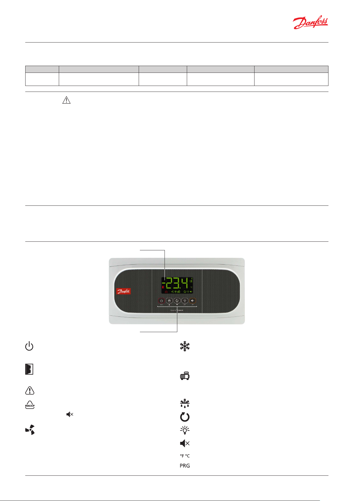
4.0 Description
Display
Keypad
Fixed: Stand-By Mode activated. Regulation is paused.
Flashing: Controlled shutdown process for the regulation
underway.
Fixed: The cold solenoid is active.
Flashing: The solenoid should be active but a delay or
protection is preventing this.
(Refer to the Fan start-up section).
Fixed: Cold room door open.
Flashing: The door has been open for a greater time than
has been defined in parameter A12.
Fixed: Compressor active.
Flashing: The compressor should be active but a delay
or protection is preventing this.
There is an active alarm, but not an active HACCP alarm.
Fixed: HACCP alarm active.
(Refer to the Compressor Protection timing section).
Defrost relay active.
Flashing: HACCP alarm registered and unconfirmed.
Press the key to confirm an HACCP alarm.
Fixed: Evaporator fans active.
Flashing: The evaporator fans should be active but a
Continuous cycle mode active.
Cold room light active.
delay is preventing this.
(Refer to the Drip time section).
Alarm in progress muted.
Temperature displayed in ° Fahrenheit / ° Centigrade.
Programming mode active.
© Danfoss | DCS (vt) | 2021.02 BC364433930186en-000101 | 3
User Guide | Temperature controller for walk-in coolers and freezers, Type AK-RC 251
80Z8117
4.1 Keypad
Pressing it for 3 seconds activates/deactivates Stand-By
mode. In this mode, regulation is paused and the power
icon is displayed.
In the programming menu, this exits the parameter
without saving changes, returns to previous level or exits
programming.
Pressing once activates/deactivates the cold room light.
Pressing it for 3 seconds accesses the condensed
programming menu.
Pressing it for 6 seconds accesses the expanded
programming menu.
In the programming menu, this accesses the level shown
on the display or, during the setting of a parameter,
accepts the new value.
Pressing once displays the temperature of probe S2 for 10
seconds (If it is enabled).
Pressing it for 3 seconds starts/stops the defrost.
In the programming menu, this allows scrolling around
the different levels, or, during the setting of a parameter,
changing its value.
Pressing once displays the current effective value of
the Set Point, taking into consideration temporary
modifications by other parameters (C10 or C12).
When an alarm is underway, pressing once mutes the
acoustic alarm. Pressing for 3 seconds accesses the Set
Point setting.
Pressing it for 3 seconds activates/deactivates continuous
cycle mode.
In the programming menu, this allows scrolling around
the different levels, or, during the setting of a parameter,
changing its value.
STAND-BY
If the temperature regulation cannot be instantly stopped due to its configuration, a controlled stop process starts and the
icon flashes. To stop the controlled stop process and force the step to Stand-by, press the Stand-by key again for 3 seconds.
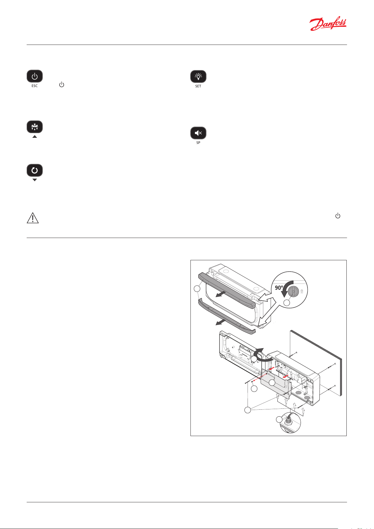
5. Installation
• Remove the bezels (1) by pulling out on one side first and then
the other side.
• Make a 1/4 turn of the screws (2) counter-clockwise and open
the door (3).
• Install the necessary glands (4) removing the provided caps.
• Mark and make the holes in the wall with the aid of the template
included.
• Fix the device to the wall. If it is a brick wall, use the screws and
anchors supplied; if the wall is made of sheet metal (cold room
store), use the screws provided without anchors (5).
• Remove the plastic cover (7) loosening the screw (6) and wire
the device by following the recommendations indicated on p. 7.
• Once the wiring is done, reinstall the plastic cover (7), close the
cover (3), tighten the screws (2) and reinstall the bezels (1)
1
2
3
Danfoss
7
6
5
4
Ø Max.25 mm
4 | BC364433930186en-000101 © Danfoss | DCS (vt) | 2021.02
User Guide | Temperature controller for walk-in coolers and freezers, Type AK-RC 251
CORECORE
1
Danfoss
CORECORE
2
Danfoss
80Z8119
6. Wiring
Always disconnect the power supply to do the wiring.
The probes and their cables should NEVER be installed in
a conduit together with power, control or power supply
cables.
For disconnection, the power supply circuit must be equipped
• The specific wiring to be performed depends on the option
selected in the initial configuration wizard.
• Use the appropriate diagram based on the option selected.
• Check the available options on the diagram sheet included
with your device.
with a switch of at least 2 A, 230 V, located near the device. The
power supply cable will be H05VV-F or NYM 1x16/3. The section to
be used will depend on the local standard in force but must never
be less than 14AWG.
Cables for relay or contactor outputs should have a section of
14AWG, allow working temperatures equal to or over 158 °F and
be installed with as few bends as possible.
The 120/230 V~ wiring must be kept clear of any other external
element.
Important:
• Before starting the installation, you must take the advice of
local regulations in force.
• The AUXILIARY relays are programmable, and their operation
depends on the configuration.
• The function of the digital inputs depends on the configuration.
• The recommended currents and powers are the maximum
working currents and powers.
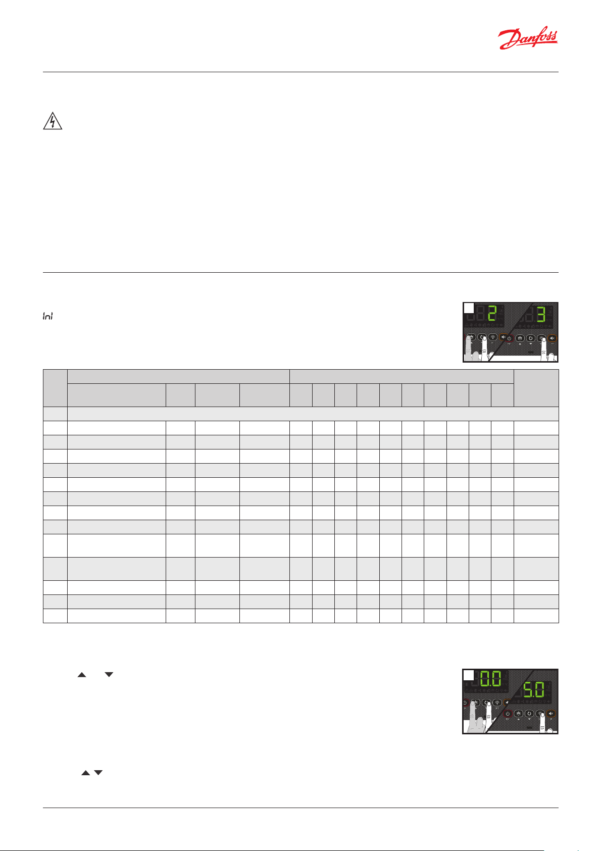
7. Initial configuration
The first time the unit is powered up, it will enter into the Wizard mode. The display will show the message
flashing with 0.
Step 1:
Select the most suitable InI option based on the type of installation to be carried out and press SET. The
available options will be shown in the following table:
Type of installation Parameters
InI
Cold regulation
0 Demo Mode: it displays the temp. but does not regulate or activate relays
1 Solenoid No Electric Yes 0 0 2 0 0 0 0 20 0 0 A
2 Solenoid + compressor Yes Electric Yes 1 1 2 7 1 0 0 20 0 0 B
3 Solenoid + compressor No Electric Yes 0 1 2 0 0 0 0 20 0 0 B
4 Solenoid No Air Yes 0 0 1 0 0 0 0 20 1 1 A
5 Solenoid + compressor Yes Air Ye s 1 1 1 7 1 0 0 20 1 1 B
6 Solenoid + compressor No Air Yes 0 1 1 0 0 0 0 20 1 1 B
7 Solenoid + compressor Yes Hot gas Yes 1 1 2 7 1 9 1 5 2 0 C
8 Solenoid + compressor No Hot gas Yes 0 1 2 0 0 9 1 5 2 0 C
9 Solenoid + compressor Ye s
10 Solenoid + compressor No
11 Solenoid No Static No 0 0 1 0 0 0 0 20 1 - A
12 Solenoid + compressor Yes Static No 1 1 1 7 1 0 0 20 1 - B
13 Solenoid + compressor No Static No 0 1 1 0 0 0 0 20 1 - B
Pump
Down
Defrost
Reversed
cycle
Reversed
cycle
Evaporator
fans
Yes 1 1 2 7 1 0 0 5 3 0 D
Yes 0 1 2 0 0 0 0 5 3 0 D
Pd
o00 I00 I10 I11 I20 I21 d1 d7 F3
80Z8118
CORECORE
Diagram
to be
used
Note: If options 2, 5, 7, 9 or 12 are chosen, check the configuration of parameter I11 according to the pressure switch type used. (See
diagram included with the device).
Step 2:
Use keys and to enter the desired Temperature Set Point value and press SET. The wizard has finished.
The unit will begin to regulate the temperature.
IIf this is not the first time you run the wizard, after completing the last step the display will show the
message dFp (default parameters). You may choose between two options:
0: Only change the parameters which affect the wizard. The other parameters will remain the same.
1: All parameters return to their factory setting except those which have been modified by the wizard.
CORECORE
Important: The wizard will not start automatically once the unit has been powered up at least once. To start the Wizard at any time turn
off the controller by pressing the power button for 3 seconds and wait until the power symbol is ON. The press the buttons listed here in
sequence , and SET.
If the pump down function is active, a certain amount of time may elapse between starting the stand-by function and the controller
stopping (see page 8).
© Danfoss | DCS (vt) | 2021.02 BC364433930186en-000101 | 5
User Guide | Temperature controller for walk-in coolers and freezers, Type AK-RC 251
Wizard parameters list
Pd Pump down active? 0=No 1=Yes
o00 Configuration of relay AUX1
I00 Connected probes 1=Probe 1 (Cold room) 2=Probe 1 (Cold room) + Probe 2 (Evaporator)
I10 Configuration of digital input 1
I11 Polarity of the digital input 1 0=Activates on closing contact 1=Activates on opening contact
I20 Configuration of digital input 2
I21 Polarity of the digital input 2 0=Activates on closing contact 1=Activates on opening contact
d1 Maximum defrost duration (0=defrost deactivated)
d7 Type of defrost
F3 Status of the fans during the defrost 0=Shut down 1=Running
0=Deactivated 1=Compressor/Crankcase heater
2=Light 3=Virtual control
0= Deactivated 1=Door contact 2=External alarm
3=Severe external alarm 4=Change of SP 5=Remote defrost
6=Defrost block 7= Low pressure switch 8=Remote Stand-by
0= Deactivated 1=Door contact 2=External alarm
3=Severe external alarm 4=Change of SP 5=Remote defrost
6=Defrost block 7=Register probe 8=Probe 2° evaporator
9=High pressure switch for Hot Gas 10=Remote Stand-by
0=Resistors 1=Air/fans 2=Hot gas
3=Reversal of cycle
8. Operation
Display messages
Pump down malfunction error (stop), the time configured in parameter C20 has been exceeded (see page 8).
Only displayed on screen.
Pump down malfunction error (start-up), the time configured in parameter C19 has been exceeded (see page 8).
Only displayed on screen.
Probe 1/2/3 failure (open circuit, crossed circuit or temperature outside the limits of the probe)
Only E2 and E3: Damp evaporator probe (see page 12).
Activates the alarm relay and the audible alarm.
Open door alarm.
Only if the door remains open for a longer time than defined in parameter A12 (see page 12).
Activates the alarm relay and the audible alarm.
Maximum temperature in control probe alarm.
The temperature value programmed in A1 has been reached (see page 12).
Activates the alarm relay and the audible alarm.
Minimum temperature in control probe alarm.
The temperature value programmed in A2 has been reached (see page 12).
Activates the alarm relay and the audible alarm.
External alarm activated (by digital input) (see page 12).
Activates the alarm relay and the audible alarm.
Severe external alarm activated (by digital input) (see page 12).
Activates the alarm relay and the audible alarm.
Alarm for defrost completed due to time-out.
The time set in d1 has been exceeded (see page 13).
Activates the alarm relay and the audible alarm.
HACCP alarm.
The temperature has reached the value of parameter h1 during a longer period than established in h2 (see page 12).
Activates the alarm relay and the audible alarm.
HACCP alarm due to a power supply failure.
The temperature established in h1 has been reached, following a power supply failure (see page 12).
Activates the alarm relay and the audible alarm.
6 | BC364433930186en-000101 © Danfoss | DCS (vt) | 2021.02

User Guide | Temperature controller for walk-in coolers and freezers, Type AK-RC 251
Solenoid
S1
Compressor
S1
80Z8121
Compressor
C7 C7C8
oss
80Z8122
Indicates that a defrost is being performed (see page 10).
Only displayed on screen.
Password request. See parameters b10 and PAS (see page 13).
Only displayed on screen.
Shown sequentially with the temperature: The controller is in demo mode, the configuration has not been made.
8.1 Cold regulation
Solenoid control (COOL Relay)
The cooling process is regulated by means of opening / closing the
solenoid valve.
When the temperature in probe S1 reaches the set point (SP) value
plus the probe's differential (C1), the solenoid opens and causes
the temperature to drop. Once the set point (SP) value is reached,
the solenoid closes.
Compressor control (Relay AUX 1)
With Pump Down (Inl: 2, 5, 7, 9, 12)
Requires the connection of a low pressure switch in digital
input 1.
When the temperature in probe S1 reaches the set point (SP) value
plus the probe’s differential (C1), the solenoid opens, causing the
pressure in the evaporator to increase and, therefore, the low
pressure switch deactivates and the compressor starts up.
Once the set point (SP) value is reached, the solenoid closes,
causing the pressure in the evaporator to decrease, triggering the
low pressure switch and stopping the compressor.
For further details of the process, see page 8.
SP+C1
SP
SP+C1
Solenoid
pressure
SP
Low
switch
ON
ON
ON
ON
Danfoss
80Z8120
Danfoss
Without Pump Down (Inl: 3, 6, 8, 10, 13)
The compressor operates simultaneously with the solenoid valve,
starting up when the latter opens and stopping when it closes.
Operation in the event of a fault in probe S1
If probe S1 fails (fault, disconnection, etc.), compressor behavior
will depend on parameter C6, with one of 3 options available:
C6=0: The compressor is stopped until probe S1 begins to
operate again.
C6=1: The compressor is started-up until probe S1 begins to
operate again
C6=2: The compressor operates in line with the average operation
during the 24 hours prior to the error, taking into account
the number of start-ups and stops and the average time in
each state (stop-start). If 24 hours have not elapsed without
a probe error, the device moves to C6=3 mode.
ON ON
Danf
C6=3: The compressor operates in line with the times
programmed in C7 (ON) and C8 (OFF).
© Danfoss | DCS (vt) | 2021.02 BC364433930186en-000101 | 7

User Guide | Temperature controller for walk-in coolers and freezers, Type AK-RC 251
ON
Liquid solenoid
1S
80Z8123
Solenoid
S1
80Z8124
Pump down function
This function provides direct control of the solenoid and the
compressor and requires the use of a low pressure switch
connected to the digital input 1. It prevents pressure problems in
the system by ensuring that the compressor operates only when
the pressure is within the correct range. Use only if controlling
both, the solenoid valve and the compressor. If controlling only
the solenoid valve, DO NOT USE THIS SETTING and use any other
of the options as it will trigger an error if the low pressure switch is
not connected.
This function is only available for Inl options 2, 5, 7, 9 and 12
STOP
When the temperature in probe S1 reaches the set point (SP)
value, the COOL relay deactivates, closing the liquid solenoid.
Because the compressor continues to operate, pressure in the
evaporator quickly drops. Upon reaching a given value, the low
pressure switch activates, changing the status of digital input 1,
which stops the compressor (relay AUX 1).
This action isolates all of the refrigerant in the high-pressure line,
far from the compressor crankcase, preventing serious faults upon
start-up.
Should the low pressure switch fail, the controller stops the
compressor once the safety interval defined in C20 has elapsed,
displaying the message “Pd” (an informative message that does
not affect the unit's operation).
If C20 time is 0 (default value), the compressor will not stop until
the low pressure switch is activated, but it will display the “Pd”
message after 15 minutes.
START
When the temperature in probe S1 reaches the set point value plus
the differential (SP+C1), the COOL relay activates, opening the liquid
solenoid. This increases the pressure in the evaporator, deactivating
the low pressure switch, which turns the compressor on.
If, some time (determined by C19) after the liquid solenoid is
opened (COOL relay set to ON), the low pressure switch does
not deactivate, the controller will once again close the solenoid
(COOL relay set to OFF) and the “LP” message will be displayed.
This action will be repeated every 2 minutes, indefinitely, until the
pressure switch is deactivated and the installation reverts to its
normal operation.
If C19 time is 0 (default value), the solenoid will remain open until
the low pressure switch deactivates, but it will display the “LP”
message after 5 minutes.
STAND-BY
If the pump down function is active, a certain amount of
time may elapse between starting the stand- by function
and the controller stopping; this is because certain
installation control phases cannot be interrupted.
To force the stop of the controller, press the Stand-by key
again for 3 seconds.
Continuous cycle mode
This is used to quickly cool the cold room stores before products
are loaded and is activated by pressing the key for 3 seconds.
Upon activating this mode, the compressor begins to operate until
the temperature in probe S1 reaches the set point value, minus the
variation indicated in parameter C10. The value of C10 is always
negative, unless it is 0.
The unit will immediately return to normal operation. Should it
not be possible to reach this point, the device will return to normal
operation once the time configured in C9 has elapsed, or by
pressing the key again for 5 seconds.
Low pressure
switch
Compressor
Pressure in
evaporator
COOL
D1
AUX 1
OFF
ON
OFF
ON
OFF
+
SP SPSP+C
SP+C1
SP
SP+C10
Pressure
switch fault
C20
Danfoss
Pressure
switch fault
C19
P+C1
Danfoss
ON ON
8 | BC364433930186en-000101 © Danfoss | DCS (vt) | 2021.02

User Guide | Temperature controller for walk-in coolers and freezers, Type AK-RC 251
Set Poin
S1
80Z8125
OFF-ON (C4=0)
80Z8126
C23
SP+C1
Set Point change mode
This allows for quick alternation between two working
temperatures in the cold room store, modifying the Set
Point in line with the value indicated in parameter C12. The
aforementioned value may be negative or positive, which allows
for the Set Point to be reduced or increased. If it is configured in 0,
the mode is disabled.
It can be activated as follows:
• By means of an external switch connected to one of the digital
inputs. The digital input should be configured as “Set Point
change (I10 or I20=4). Activation through this method cancels
any other activation and can only be deactivated using the same
method.
Parameter C0 allows for correction of the temperature detected
by probe 1; this is particularly useful when the probe cannot be
located in the ideal place.
Set Point locking
Parameters C2 and C3 allow for an upper and lower limit to
be established for the set point (SP), to protect the product or
installation from Set Point manipulation.
Compressor protection timing
Parameter C4 allows for selection of the type of timing to
be applied to protect the compressor. These delays prevent
continuous compressor starts and stops.
These timings affect the COOL and AUX 1 relays (if o00=1)
OFF-ON (C4=0): Minimum time in OFF mode before each start-up.
OFF-ON / ON-OFF (C4=1): Minimum time in ON and OFF mode for
each cycle. The delay time is defined by means of parameter C5; if
C5=0, timing is disabled.
EXAMPLE 1:
Calibration of probe 1
Configuration
I10: 4
0I11:
t
change
DIG.IN
D1
Gnd
(SP+C12)+C1
D2 / S3
ON
COOL
OFF
SP+C1
SP+C12
Solenoid
SP
Danfoss
SP
ON ON
D1
D1= OND1= OFF
Danfoss
SP+C1
C5
8.2 Door management
Door management allows for the installation's behavior to be
controlled, should the cold room door open through parameters
C22 and C23.
Parameter C22 defines whether cooling should be stopped if the
door opens. If C22=1, when the door opens, the fans stop and, 15
seconds later, the solenoid closes (COOL relay).
Parameter C23 defines the maximum time, in minutes, that the
installation can remain without cooling whilst the door is open. If
C23=0, cooling does not occur with the door open.
Management of door frame resistor
If the Set Point is equal to or below 25 °F and the relay AUX 2 has
been configured as “door frame resistor” (o10=4), the resistor is
activated (relay ON) when the temperature of the cold room drops
below 26 °F, and is deactivated (relay OFF) when 32 °F is reached.
COOL
S1
SP
Door
COOL
OFF-ON / ON-OFF (C4=1)
ON
OFF
Configuration:
C22: 1
5C23:
ON ON
SP
SP+C1
C5C5
Open
Danfoss
80Z8127
© Danfoss | DCS (vt) | 2021.02 BC364433930186en-000101 | 9

User Guide | Temperature controller for walk-in coolers and freezers, Type AK-RC 251
F4
Máx.d1 d3d9
80Z8129
8.3 Defrost
Types of defrost
There are 5 possible defrost types, depending on the option
selected in the wizard (Inl):
Electric (InI=1, 2 and 3) (d7=0)
Defrost is performed through electrical resistors, supplying the
evaporator with heat. The operation of fans in this mode depends
on parameter F3; the compressor and solenoid are stopped.
By air (InI=4, 5 and 6) (d7=1)
Usually used in positive cold rooms (> 37 °F), since the inside
temperature of the cold room is sufficient to melt evaporator ice.
By default, the fans are activated so that air may circulate through
the evaporator; to stop them, change parameter F3 to 0. The
compressor and solenoid are stopped.
Static (InI=11, 12 and 13)
In this type of installation, there are no evaporator fans and defrost
is performed by stop cooling.
Hot gas (InI=7 and 8) (d7=2)
The hot gas from compressor discharge is used to melt evaporator
ice and, to this end, two valves are necessary: one at the condenser
input (A) (SSV relay) and another between the compressor output
and the evaporator input (B) (DEF relay).
DIG.IN
D1
Gnd
D2 / S3
D
A
B
EVAP.
During the process, the liquid solenoid valve (C) and the
condenser input valve are closed and the evaporator input valve
is opened, forcing hot gas to pass through the latter and melting
the ice.
Optionally, a high pressure switch (D) can be added to control the
solenoid valve (digital input D2, l20=9) during the defrost process
using hot gas. If the pressure decreases, the solenoid opens to
allow liquid into the tank; when the pressure rises again, the
solenoid closes.
COND.
SSV
.
N
N
FA
N
DEF
N
C
UX 1
H. CRANK
N
N
COOL
A
Danfoss
N
80Z8128
Reversed cycle (InI=9 and 10) (d7=3)
A 4-way valve is used to invert the refrigeration cycle, using the
evaporator as a condenser to melt the ice formed. The process
begins by stopping the cooling process (if it is active). If Pump
Down is active, defrost begins once the action is complete.
Next, the 4-way valve is activated (DEF relay ON), alongside the
solenoid (COOL relay ON) and the compressor (AUX 1 ON), and
the defrost process begins. D1 time begins to be counted after the
COOL relay is activated.
8.4 Defrost control
Defrost start
Defrost will start if:
• The time programmed in parameter d0 has elapsed since the
start of the last defrost.
• We press the key for 3 seconds.
• By means of an external push-button (I10 / I11=5).
Defrost completion
Defrost will complete if:
• The temperature programmed in parameter d4 has been
reached in probe 2. This requires a 2nd probe (l00=2) to be
available, located in the evaporator.
• The time configured in parameter d1 has elapsed (maximum
defrost duration).
• We press the key for 5 seconds.
• By means of an external push-button (I10 / I11=5).
When defrost is complete, the action can be stopped in two
possible ways:
• Pump down active (Inl=9): The solenoid closes (COOL relay OFF)
and the 4-way valve returns to its initial position (DEF relay OFF)
while the compressor continues to operate (AUX 1 relay ON),
until the low pressure switch activates, stopping the compressor
(AUX 1 relay OFF), starting the drip time.
• Without Pump Down (Inl=10): The solenoid closes (COOL relay
OFF) and the 4-way valve returns to its initial position (DEF relay
OFF) and the compressor stops (AUX 1 relay OFF), starting the
drip time.
COLD REGULATION
S1
DEFROST
DRIPTIME
"DEF” MESSAGE
COLD REGULATION
FAN START-UP
DELAY
d0
DEFROST
d4
SP+C1
SP
Danfoss
Drip time
This is established through parameter d9 and sets the time added
at the end of defrost to allow for the removal of surplus water from
melted evaporator ice, during which there is no cooling.
10 | BC364433930186en-000101 © Danfoss | DCS (vt) | 2021.02

User Guide | Temperature controller for walk-in coolers and freezers, Type AK-RC 251
S2
F
80Z8130
Fan start-up delay
This is established through parameter F4 and allows for the
possible drops left in the evaporator to freeze before the fans
activate, preventing them from being projected into the cold
room. It also prevents heat being supplied to the cold room due to
defrost in the evaporator.
Note: If defrost is cancelled before 1 minute has elapsed, the drip
time (d9) is not applied and the fans are activated without taking
into account the start-up delay (F4).
If defrost is by air or is static, the drip time (d9) and fan start-up
delay (F4) are deactivated.
Message displayed during defrost
This is established using parameter d2, and you can choose
between displaying the real temperature captured by probe 1
(d2=0), showing the temperature captured by probe 1 at the
start of the defrost (d2=1), or displaying the dEF (d2=2) message.
Parameter d3 defines the time during which the aforementioned
message will be displayed once the drip time (d9) and fan stop
time (F4) are complete.
Remote defrost
This function allows defrost of the unit to be activated using an
external button, connecting it to one of the digital inputs that
must be configured as remote defrost (I10 or I20=5) .
Defrost locking
This prevents defrost starting at unusual points by means of
an external switch, which may be useful for ensuring that the
installation's load does not excessively increase, exceeding the
permitted limits.
The external switch must be connected to one of the digital
inputs, which should be configured as “Defrost locking” (I10 or
I20=6).
Defrost of a second evaporator
This function allows for defrost to be controlled in a second
evaporator, provided that defrost is by electric heat, by air or is
static. The same type of defrost should be used for the first and
second evaporators.
This requires configuration of input 2 as a 2nd evaporator probe
(l20=8). In the event of an error in the 2nd evaporator probe,
defrost completes once the time defined in d1 has elapsed.
Electric defrosting
This requires configuration of relay AUX 2 as 2nd evaporator
defrost (o10=5).
Defrost begins simultaneously in both evaporators. When the
probe of evaporator 1 reaches the temperature defined in d4,
the DEF relay deactivates, completing defrost of evaporator 1.
Defrost of evaporator 2 is completed when the evaporator 2 probe
reaches the temperature defined in d4. Drip time begins when
both defrosts are complete.
Defrost by air
The fans of both evaporators are connected in parallel to the FAN
relay.
Defrost begins simultaneously in both evaporators and does not
complete until both probes reach the temperature defined in d4.
Drip time subsequently begins.
Static defrost
Defrost begins simultaneously in both evaporators and does not
complete until both probes reach the temperature defined in d4.
Drip time subsequently begins.
Other parameters
Using parameter d5, you can configure whether the unit performs
a defrost (d5=1) or not (d5=0) when it receives power (first startup or after a power supply failure). Should the option YES (d5=1)
be selected, defrost will begin once the delay time defined in d6
has elapsed.
Using parameter d8, we define the time tally established in
d0, choosing between total time elapsed (d8=0) or the sum of
compressor operation time (d8=1).
Remark: If parameter d1 is configured to 0, no defrosts are
performed.
8.5 Fan control
Fans are controlled through probe 2 (evaporator) and parameters
F0 (stop temperature) and F1 (probe differential). If probe 2 is
not connected or an error in the probe (E2) is detected, the fans
continuously operate without taking into account parameters
F0 and F1, but taking the remaining parameters (F2 to F4) into
account.
Using parameter F2, the status of the fans during compressor
stops is defined. Using parameter F3, the status of the fans during
defrost is defined.
Parameter F4 defines the fan start-up delay time after defrost.
Parameter C22 defines whether fans stop when the door is
opened.
© Danfoss | DCS (vt) | 2021.02 BC364433930186en-000101 | 11
ans
F0
F0-F1
COOL
F2=0
F2=1
SP SP
SP+C1
ON ON
ON
ON ON
Danfoss

User Guide | Temperature controller for walk-in coolers and freezers, Type AK-RC 251
8.6 Alarms
The device warns the user through an on-screen message,
activation of a relay (only if o10=1) and a sound alarm when the
criteria programmed in the parameters are met.
Maximum / minimum temperature alarm
It shows the message “AH” or “AL” when the temperature in probe
1 reaches the value configured in parameters A1 (maximum
temperature) and A2 (minimum temperature).
This value may be:
• Absolute (A0=1): The temperature at which the alarm should
activate must be indicated in A1/A2.
• Relative to the SP (A0=0): The increase or decrease in the
number of degrees necessary for the alarm to activate, in
relation to the set point, must be indicated in A1/A2. This option
enables us to change the set point without having to reset the
maximum and minimum alarms.
Parameter A10 establishes the differential of both parameters
(Hysteresis).
Note: We configure the following parameters in a controller: SP=2,
A1=10, A10=2
• If A0=0 (Relative to the SP), the maximum temperature alarm
will activate when 12 degrees are reached in probe 1, and will
deactivate when 10 degrees are reached.
• If A0=1 (Absolute), the maximum temperature alarm will
activate when 10 degrees are reached in probe 1, and will
deactivate when 8 degrees are reached.
External alarm / severe external alarm
The message AE (External alarm) or AES (Severe external alarm) is
displayed when the digital input configured as external alarm or
severe external alarm is activated.
The severe external alarm also deactivates all the loads and,
therefore, temperature regulation stops. When this alarm
disappears, the device returns to its normal operation.
At least one of the digital inputs must be configured as an external
alarm (I10 or I20=2) or as a severe external alarm (I10 or I20=3).
Probe error alarm
If one of the enabled probes is crossed, in open circuit or out of
range, the message
E1, E2 or E3 will be shown, depending on whether probe S1, S2 or
S3 is involved.
Evaporator probe error alarm due to moisture ingress
If, at the start of defrost, the temperature in probe S2 is 40 °F
higher than the temperature in probe S1, the controller ignores
probe S2 and defrost is instead completed based on defrost time.
The display shows the message E2, activates the alarm relay and
sound alarm.
The alarm can be silenced, but the B alarm icon will not disappear
until:
• The controller is switched off and then on again.
• Defrost without error is started in probe S2.
If the 2nd evaporator probe (l20=8) has been enabled, it will
behave in the same way, but displaying the message E3.
Open door alarm
The door has been open for a longer time than defined in
parameter A12, the open door alarm is activated.
In order to detect the open door, configuration is required of one
of the digital inputs as “door contact” (I10 or I20=1).
Activates alarm relay and sound alarm.
HACCP alarm
The alarm is activated should situations be detected which could
endanger the integrity of the products stored in the cold room.
If the temperature of the cold room is higher than that defined
in parameter h1 for a length of time exceeding that defined in
parameter h2, the alarm activates, displaying the message HCP. on
screen.
Upon pressing the mute key, the sound alarm switches off, but the
alarm remains.
Once the temperature drops below parameter h1, if the mute
key has been pressed, the alarm disappears. If the mute key has
not been pressed, the audible alarm deactivates but the HACCP
indicator remains in flashing mode, indicating than a nonconfirmed HACCP alarm has occurred.
Press the mute key to confirm an HACCP alarm.
If, during a power failure, a HACCP alarm occurs, when the power
supply returns, the HACCP alarm is activated and the display
shows the messages HCP and PF (power failure) alternately.
Alarm delays
These delays prevent certain alarms from being shown, to allow
the installation to recover its normal operation after certain events.
• Delays in start-up (A3): This delays the activation of the
temperature alarms upon receiving power (at start-up or after
a power supply failure) or when exiting Stand-by mode. This
allows for the installation to start up avoiding alarms.
• Delay after a defrost (A4): This delays the activation of the
temperature alarms when a defrost completes.
• Delay to minimum and maximum temperature alarm (A5): This
delays the activation of the maximum (A1) and minimum (A2)
temperature alarms, from when the temperature in probe 1
reaches the programmed value.
• Delay to activation of external alarm (A6): This delays the
activation of the external alarm, from when the digital input
becomes active.
• Delay to deactivation of external alarm (A7): This delays the
deactivation of the external alarm, from when the digital input
becomes active.
• Delay to open door alarm (A12): This delays the activation of the
alarm upon detecting that the door is open.
12 | BC364433930186en-000101 © Danfoss | DCS (vt) | 2021.02

User Guide | Temperature controller for walk-in coolers and freezers, Type AK-RC 251
(I10 =8)
DIG. IN
Configuration of alarm relay
Should any relay have been configured as an alarm relay,
parameter A9 allows for the relay status to be defined when an
alarm is triggered:
• A9=0 Relay active (ON) in the event of an alarm (OFF without
alarm)
• A9=1 Relay inactive (OFF) in the event of an alarm (ON without
alarm)
8.7 Alerts
The device alerts the user through an on-screen message when
an event occurs which requires his/her attention. However, it does
not activate the sound alarm or the alarm relay (if active).
Defrost finished by time alarm
The message Adt is displayed when a defrost has completed due
to time-out, if parameter A8=1.
Pump down malfunction error (stop)
The message Pd is displayed if a malfunction is detected when the
refrigeration system is stopped using the pump down action. (See
page 8).
Pump down malfunction error (start-up)
Displays the LP message if a malfunction is detected when the
refrigeration cycle is started up using the pump down action. (See
page 8).
8.8 Light control
Relay AUX 1 or AUX 2 must be configured as “Light” (o00 or
o10=2).
Switching the lights on or off is controlled using:
The push-button: One press switches the lights on or off.
The cold room door: When the door is opened, the lights remain
on for the time defined by parameter b01. If the value is 0, when
the door closes the lights go out. (One of the digital inputs must
be configured as door contact (I10 or I20=1).
The control even occurs with the equipment in Stand-by.
8.9 Password
It allows protecting the configuration of the unit using a 2 digit
code (from 01 to 99). If it is active a code is requested when you try
to access the programming menu. This menu cannot be accessed
if a wrong value is entered. The code is set via the PAS parameter.
Parameter b10 defines the operation of this code.
8.10 Remote Stand-by mode
Danfoss
80Z8131
D1
Gnd
D2 / S3
Remote
Stand-by
This allows activating Stand-by mode using a switch connected to
one of the digital inputs. Said digital input must be set to Stand-by
remote activation (I10=8 or I20=12).
8.11 Operation of the auxiliary relays
Depending on the controller model, it may have 1 or 2 auxiliary
relays. The function of these relays is configurable through the
parameters menu.
AUX 1 relay
• Deactivated (o00=0): It does not carry out any function.
• Compressors / crankcase resistor (o00=1): Controls
compressor operation. When the compressor is not in operation,
it powers the crankcase resistor. This function can only be
selected via the initial wizard (Inl).
• Light (o00=2): This regulates the operation of cold room light.
AUX 2 relay
• Deactivated (o10=0): It does not carry out any function.
• Alarm (o10=1): This activates the relay every time that an alarm
occurs
• Light (o10=2): This regulates the operation of cold room light
• Door frame resistor (o10=4): This controls the operation of the
cold room’s door frame resistor.
• Defrost 2º evaporator (o10=5): This controls the defrost
resistors of a second evaporator.
• Same as solenoid status (o10=6): Imitates solenoid status:
active if the solenoid is in ON mode, inactive if the solenoid is in
OFF mode.
• Same as unit status (o10=7): Indicates the unit’s status: active if
the unit is in ON mode, inactive if the unit is in Stand-by mode.
© Danfoss | DCS (vt) | 2021.02 BC364433930186en-000101 | 13

User Guide | Temperature controller for walk-in coolers and freezers, Type AK-RC 251
T
9. Configuration
Condensed programming menu
This allows for the most-used parameters to be quickly configured.
Press the SET key for 3 seconds to access it.
OUT OF
PROGRAMMING
emperature control
3 seg.
20 sec.
Parameters
Change
parameter
IN PROGRAMMING
OK
Values
Change
value
OK
20 sec.
OK
Parameters
Level 2 Description Values Min. Def. Max.
SP Temperature setting (Set Point) ºF -58 0.0 210
C1 Probe 1 differential (Hysteresis) ºF 0.2 3.6 36
d0 Defrost frequency (Time between 2 starts) H. 0 6 96
d1 Maximum defrost duration (0=defrost deactivated) Min. 0 * 255
d4 Final defrost temperature (by probe) (If I00 ≠1) ºF -58 46.4 122
F3 Status of the fans during the defrost 0=Shut down; 1=Running 0 0 1
A1 Alarm for maximum in probe 1 (It should be higher than the SP) ºF A2 210 210
A2 Alarm for minimum in probe 1 (It should be lower than the SP) ºF -58 -58 A1
Save changes
Do not save changes
Danfoss
80Z8132
Extended programming menu
Use the extended programming menu to configure all of the unit’s
parameters in order to adapt it to your installation requirements.
Press the SET key for 6 seconds to access it.
Important:
• If the password function has been configured as a keypad lock
(b10=2), or as an access to parameters block (b10=1), you will
OUT OF
PROGRAMMING
Temperature
indication
6 sec.
Level 1
Menus
Change
menu
20 sec.20 sec.
IN PROGRAMMING
Level 2
Parameters
Change
parameter
OKOK
Level 3
Values
Change
value
Save changes
Do not save changes
OK
be requested to enter the password programmed in PAS when
attempting to access either of the two functions. If the entered
password is not correct, the unit will go back to showing the
20 sec.
temperature.
• Certain parameters or menus may not be visible depending on
the configuration of the rest of the parameters.
OK
OK
Danfoss
80Z8133
14 | BC364433930186en-000101 © Danfoss | DCS (vt) | 2021.02

User Guide | Temperature controller for walk-in coolers and freezers, Type AK-RC 251
Regulation and control
Level 1 Level 2 Description Values Min. Def. Max.
SP Temperature setting (Set Point) ºF -58 32.0 210
C0 Probe 1 calibration (Offset) ºF -36.0 0.0 36.0
C1 Probe 1 differential (Hysteresis) ºF 0.1 3.6 36
C2 Set Point top locking (it cannot be set above this value) ºF -58 210 210
C3 Set Point bottom locking (it cannot be set below this value) ºF -58 -58 C2
Type of delay for the protection of the compressor:
C4
0=Minimum time of compressor in OFF
1=Minimum time of compressor in OFF and in ON in each cycle
C5 Protection delay time (Value of the option selected in parameter C4) Min. 0 0 120
COOL relay status with fault in probe 1:
C6
0=OFF; 1=ON; 2=Average according to last 24 h prior to probe error
3=ON-OFF according to prog. C7 and C8
Relay time in ON in the event of probe 1 failure
C7
(If C7=0 and C8≠0, the relay will always be disconnected in OFF)
Relay time in OFF in the event of probe 1 failure
C8
rE
C10
C12
C19
C20 Maximum time for pump down (0= deactivated) Min. 0 0 15
C21
C22 Stop fans and compressor on opening door 0=No, 1=Yes 0 0 1
C23 Start-up delay for fans and compressor with door open Min. 0 0 999
C27 Probe 3 calibration (Offset) ºF -36.0 0.0 36.0
(If C8=0 and C7≠0, the relay will always be connected in ON)
C9 Maximum duration of the continuous cycle mode. (0=deactivated) H. 0 0 48
Variation of the Set Point (SP) in continuous cycle mode. When it reaches this point
(SP+C10), it reverts to the normal mode. (SP+C10 ≥ C3).
The value of this parameter is always negative, unless it is 0. (0=OFF)
Variation of the Set Point (SP) when the change Set Point function is active. (SP+C12 ≤
C2) (0= deactivated)
Maximum start time from Pump Down
(Values between 1 and 9 seconds will not be accepted) (0=deactivated)
Probe to be displayed 0=All probes (sequential)
1=Probe 1 (Cold Room), 2=Probe 2 (Evaporator), 3=Probe 3 (According to I20)
EP Exit to level 1
Min. 0 10 120
Min. 0 5 120
ºF 0 -90 C3-SP
ºF C3-SP 0.0 C2-SP
Sec. 0 0 120
0 0 1
0 2 3
0 1 3
Defrost
Level 1 Level 2 Description Values Min. Def. Max.
d0 Defrost frequency (Time between 2 starts) H. 0 6 96
d1 Maximum defrost duration (0=defrost deactivated) Min. 0 * 255
Type of message during the defrost:
d2
0=Displays the real temperature; 1=Displays the temperature at the start of
the defrost; 2=Displays the dEF message
Maximum duration of the message
d3
(Time added at the end of the defrost process)
d4 Final defrost temperature (by probe) (If I00 ≠ 1) ºF -58 46.4 122
dEF
Defrost on connecting the unit:
d5
0=NO First defrost according to d0; 1=YES, First defrost according to d6
d6 Delay of the defrost start on connecting the unit Min. 0 0 255
d7**
Type of defrost:
0=Resistors; 1=Air/fans, 2=Hot gas; 3=Reversal of cycle
Count of time between defrost periods:
d8
0=Total real time, 1 =Sum of compressor connected time
d9 Drip time when completing defrost (Shutdown of compressor and fans) Min. 0 1 255
EP Exit to level 1
* According to wizard.
** It can only be modified using the configuration wizard (InI).
Min. 0 5 255
0 2 2
0 0 1
0 * 3
0 0 1
© Danfoss | DCS (vt) | 2021.02 BC364433930186en-000101 | 15

User Guide | Temperature controller for walk-in coolers and freezers, Type AK-RC 251
Evaporator fans
Level 1 Level 2 Description Values Min. Def. Max.
F0 Shutdown temperature of fans ºF -58 113 122
F1 Probe 2 differential if fans are shut down ºF 0.1 3.6 36
F2 Shut down fans when the compressor shuts down 0=No, 1=Yes 0 0 1
FAn
F3 Status of the fans during the defrost 0=Shut down; 1=Running 0 0 1
Delay of start-up after defrost (If F3=0)
F4
It will only actuate if it is higher than d9
EP Exit to level 1
Min. 0 2 99
Alarms
Level 1 Level 2 Description Values Min. Def. Max.
A0 Configuration of the temperature alarms 0=Relative to SP 1=Absolute 0 1 1
A1 Alarm for maximum in probe 1 (It should be higher than the SP) ºF A2 210 210
A2 Alarm for minimum in probe 1 (It should be lower than the SP) ºF -58 -58 A1
A3 Delay of temperature alarms in the start-up Min. 0 0 120
A4 Delay of temperature alarms from the end of a defrost Min. 0 0 99
A5 Delay of temperature alarms from when the A1 or A2 value is reached 0 30 99
Delay of the external alarm/Severe external alarm on receiving a signal in
AL
A6
digital input (I10 or I20 =2 or 3)
Delay of external alarm deactivation/Severe external alarm deactivation
A7
when the signal in digital input disappears (I10 or I20=2 or 3)
A8 Show warning if the defrost ends for maximum time, 0=No, 1=Yes 0 0 1
Relay alarm polarity
A9
0= Relay ON in alarm (OFF without alarm); 1= Relay OFF in alarm (ON
without alarm)
A10 Differential of temperature alarms (A1 and A2) ºF 0.1 1.8 36
A12 Delay of open door alarm (If I10 or I20=1) Min. 0 10 120
EP Exit to level 1
Min. 0 0 120
Min. 0 0 120
0 0 1
Basic configuration
Level 1 Level 2 Description Values Min. Def. Max.
b00 Delay of all functions on receiving power supply Min. 0 0 255
b01 Cold room light timing Min. 0 0 999
Function of password
0=Inactive, 1=Block access to parameters, 2=Block keypad
Communication speed:
0=9600 bps, 1=19200 bps, 2=38400 bps, 3=57600 bps
EP Exit to level 1
0 0 2
bps 0 0 3
bcn
b10
PAS Access code (Password) 0 0 99
b20 MODBUS address 1 1 247
b21
b22 Acoustic alarm enabled: 0= No, 1=Yes 0 1 1
Unt Work units: 0=ºC, 1=ºF 0 1 1
16 | BC364433930186en-000101 © Danfoss | DCS (vt) | 2021.02

User Guide | Temperature controller for walk-in coolers and freezers, Type AK-RC 251
Inputs and outputs
Level 1 Level 2 Description Values Min. Def. Max.
Connected probes
1=Probe 1 (Cold room), 2=Probe 1 (Cold room) + Probe 2 (Evaporator)
Configuration of digital input 1
0= Deactivated, 1=Door contact, 2=External alarm,
3=Severe external alarm, 4=Change of SP, 5=Remote defrost,
6=Defrost block, 7= Low pressure switch, 8=Remote Stand-by
Polarity of the digital input 1
0=Activates on closing contact; 1=Activates on opening contact
Configuration of digital input 2
0= Deactivated, 1=Door contact, 2=External alarm,
3=Severe external alarm, 4=Change of SP, 5=Remote defrost,
6=Defrost block, 7=Register probe, 8=Probe 2° evaporator,
9=High pressure switch for Hot Gas, 10=Remote Stand-by
Polarity of the digital input 2
0=Activates on closing contact; 1=Activates on opening contact
Configuration of relay AUX1
0=Deactivated, 1=Compressor/Resistor sump, 2=Light, 3=Virtual control
Configuration of relay AUX2
0=Deactivated, 1=Alarm, 2=Light, 3=Virtual control,
4=Door frame resistance, 5=Defrost 2° evaporator,
6=Same as solenoid status, 7=Same as unit status
EP Exit to level 1
1 2 2
0 * 8
0 * 1
0 0 10
0 0 1
0 * 3
0 2 7
In0
I00
I10**
I11
I20
I21
O00**
O10
* According to wizard.
** It can only be modified using the configuration wizard (InI).
HACCP alarm
Level 1 Level 2 Description Values Min. Def. Max.
h1 Maximum temperature of HACCP alarm ºF -58 210 210
HCP
h2 Maximum permitted time for activation of the HACCP alarm (0=Disabled) H. 0 0 255
EP Exit to level 1
Information (reading only)
Level 1 Level 2 Description Values Min. Def. Max.
InI Option chosen in the configuration wizard
Pd** Pump down active? 0=No, 1=Yes
PU Program version
tid
Pr Program revision
bU Bootloader version
br Bootloader revision
PAr Parameter map revision
EP Exit to level 1
** It can only be modified using the configuration wizard (InI).
© Danfoss | DCS (vt) | 2021.02 BC364433930186en-000101 | 17

User Guide | Temperature controller for walk-in coolers and freezers, Type AK-RC 251
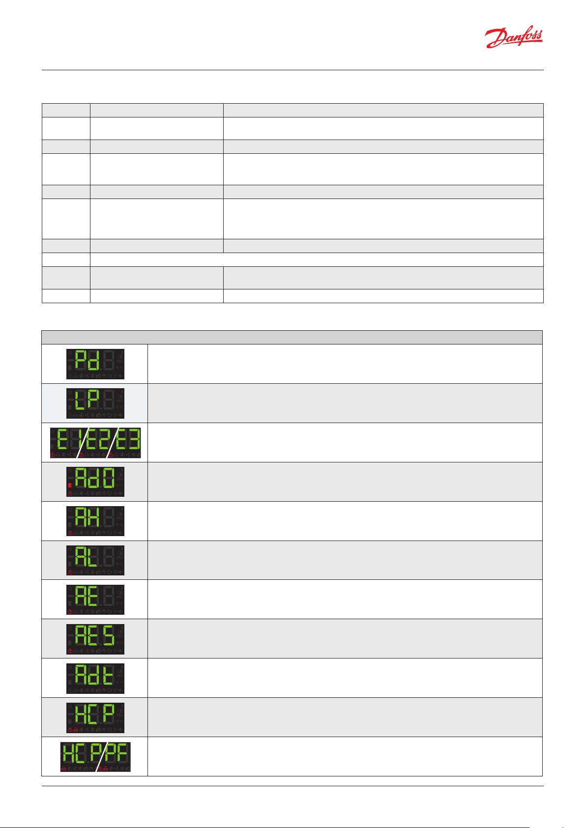
Messages
Messages A R
Pd Pump down malfunction error (Shutdown)
LP Pump down malfunction error (Start-up)
E1/E2/E3 Probe 1/2/3 failure (Open circuit, crossed circuit or temperature outside the limits of the probe)
Ad0 Open door alarm. Only if the door stays open for a greater time than is indicated in parameter A12
AH Maximum temperature alarm in control probe. The temperature value programmed in A1 has been reached
AL Minimum temperature alarm in control probe. The temperature value programmed in A2 has been reached
AE External alarm activated (by digital input)
AES Severe external alarm activated (by digital input)
Adt Defrost alarm concluded due to time-out. The time established in d1 has been exceeded
HCP
hCP + PF
dEF Indicates that a defrost is being performed
PAS Access code (Password) request. See parameters b10 and PAS
S1 - S2
A: Activates the acoustic alarm
R: Activates the alarm relay
HACCP alarm. The temperature has reached the value of parameter h1 during a longer period than has been
established in h2
HACCP alarm due to a fault in the power supply. The temperature established in h1 has been reached following a
fault in the power supply
Shown sequentially with the temperature: The controller is in demo mode, the configuration has not been
made.
18 | BC364433930186en-000101 © Danfoss | DCS (vt) | 2021.02

User Guide | Temperature controller for walk-in coolers and freezers, Type AK-RC 251
10. Technical specifications
Features Specifications
Power supply 100 - 240 V~, 50 - 60 Hz
Maximum input power in the operation 8.1 VA
Maximum nominal current 15 A
NO
Relay DEFROST - SPDT - 20 A
NC
Relay FAN - SPST - 16 A
Relay COOL - SPST - 16 A
NO
Relay AUX 1 - SPDT - 20 A
NC
NO
Relay AUX 2 - SPDT - 16 A
NC
No. of relay operations EN60730-1:100.000 operations
Probe temperature range -58 – 211 ºF
Resolution, setting and differential 0.2 ºF
Thermometric precision ±1.8 ºF
Loading tolerance of the NTC probe at 25 °C ±0.7 ºF
Working ambient temperature 14 – 122 ºF
Storage ambient temperature -22 – +140 ºF
Protection degree IP 40 (IP 65 installing the proper glands)
Pollution degree II acc. UL 60730-1
Construction Independently mounted acc. UL 60730-1
Control device classification
Temperature during ball-pressure test
Current of radio jamming suppression tests 270 mA
Voltage and current as per EMC tests 207 V, 17 mA
Type of assembly Fixed internal
MODBUS address Shown on label
Dimensions 11.42 in (W) x 5.55 in (H) x 3.32 in (D)
Internal buzzer
EN60730-1: 15 (15) A 250 V~
UL-60730: 9 FLA 54 LRA, 240 V AC
UL-60730: RES 12 A, 240 V AC)
EN60730-1: 15 (13) A 250 V~
UL-60730: 6 FLA 36 LRA, 240 V AC
UL-60730: RES 6 A, 240 V AC
EN60730-1: 12 (9) A 250 V~
UL-60730: 5 FLA 30 LRA, 240 V AC
UL-60730: RES 10 A, 240 V AC
EN60730-1: 12 (9) A 250 V~
UL-60730: 5 FLA 30 LRA, 240 V AC
UL-60730: RES 10 A, 240 V AC)
EN60730-1: 15 (15) A 250 V~
UL-60730: 9 FLA 54 LRA, 240 V AC
UL-60730: RES 12 A, 240 V AC
EN60730-1: 15 (13) A 250 V~
UL-60730: 6 FLA 36 LRA, 240 V AC
UL-60730: RES 6A, 240 V AC
EN60730-1: 12 (9) A 250 V~
UL-60730: 5 FLA 30 LRA, 240 V AC
UL-60730: RES 10 A, 240 V AC
EN60730-1: 10 (8) A 250 V~
UL-60730: 5A, 240 V AC
Built-in assembly, with Type 1.B automatic operation action feature, for use in clean situations,
logical support (Software) class A and continuous operation.
Double isolation between power supply, secondary circuit and relay output.
Accessible parts: 167 ºF
Parts which position active elements: 257 ºF
© Danfoss | DCS (vt) | 2021.02 BC364433930186en-000101 | 19

Danf
already on order pro
All trademarks in this material are property of the respec
11. Ordering
Controller
Model Description Comments Code no.
Includes:
AK-RC 251 AK-RC 251 Gen. 2,5 O/P, Single phase
Accessories (for spares and replacement purposes):
Name Features Qty Code no.
3.5 m, NTC 10K Sensor Thermo plastic rubber probe 1 084N3210
8.5 m, NTC 10K sensor Thermo plastic rubber probe 50 084N3208
1.5 m, NTC 10K sensor Stainless steel probe 150 084N3200
• 1 x 1.5 m, NTC 10K sensor
• 1 x 3 m, NTC 10K sensor
• 2 x 2 caps to provide IP65 protection after installation
080Z5000
oss can accept no responsibility for possible errors in catalogues, brochures and other printed material. Danfoss reserves the right to alter its products without notice. This also applies to products
vided that such alterations can be made without subsequential changes being necessary eady agreed.
© Danfoss | DCS (vt) | 2021.02 BC364433930186en-000101 | 20
tive companies. Danfoss and the Danfoss logotype are trademarks of Danfoss A/S. All rights reserved.
 Loading...