

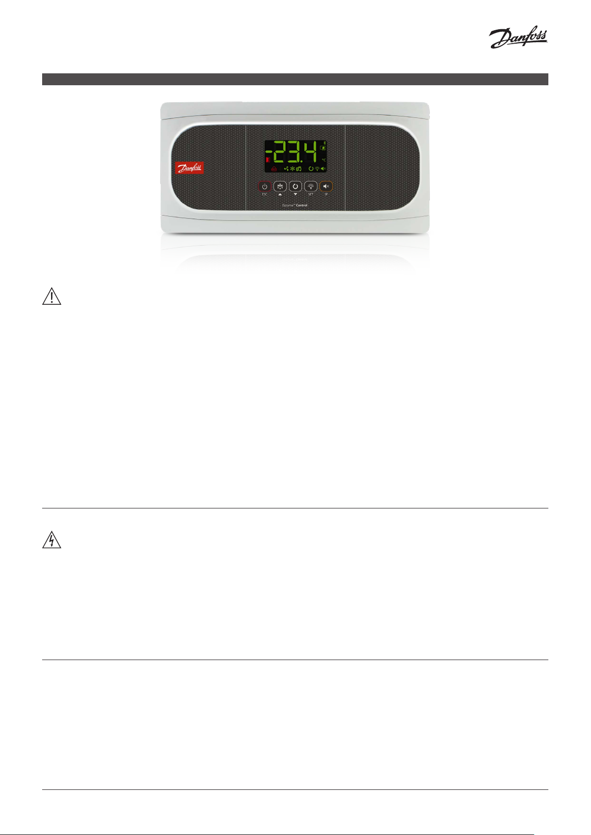
Installation Guide
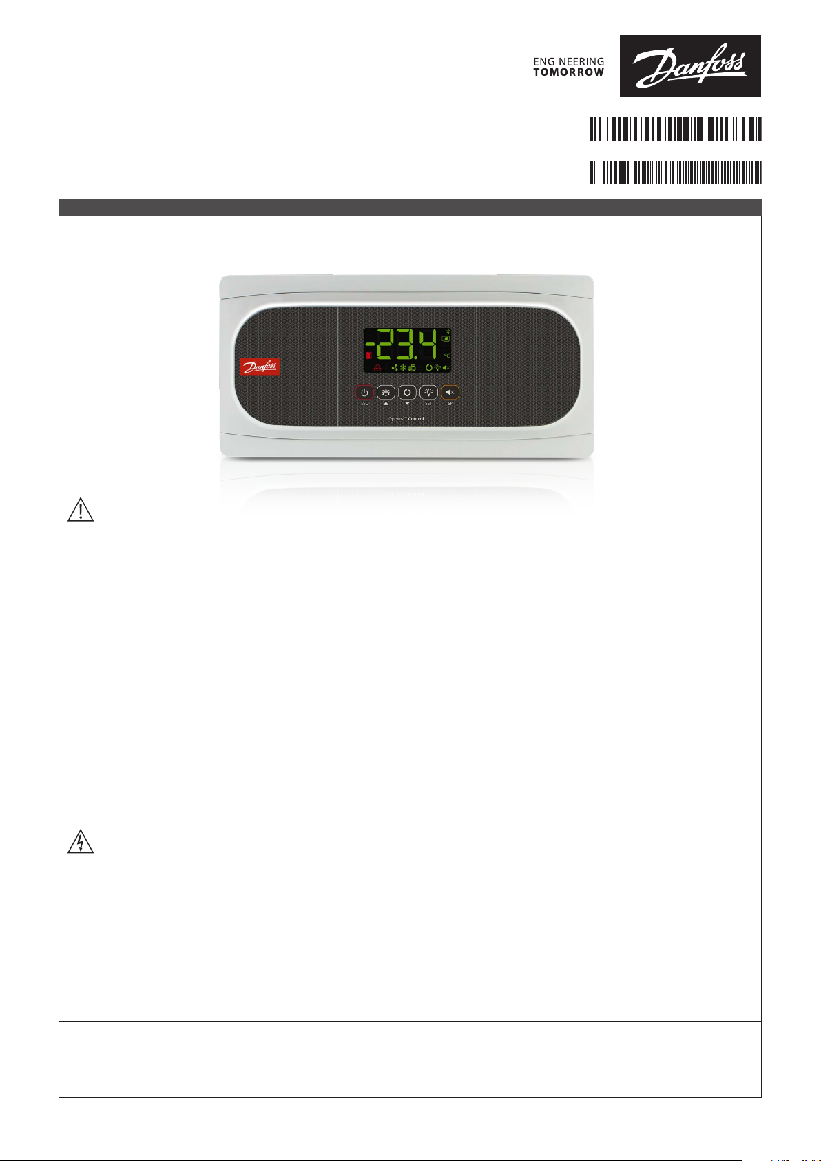
Temperature controller for walk-in coolers
080 R9291
and freezers, Type AK-RC 251
AN362928 67744601-0 0 0101
ENGLISH
EN : Temperature controller for walk-in coolers and freezers
ES : Controlador de temperatura para cuartos fríos y congeladores
Type AK-RC 251
Warnings
• Using the unit without observing the manufacturer's instructions may alter the appliance's safety requirements. Only NTC probes
supplied by Danfoss should be used for the unit to operate correctly.
• From -40 – +68 °F, if the NTC probe is extended to 3,280 ft with at least 20AWG cable, the maximum deviation will be 0.45 °F.
• It should be installed in a place protected from vibrations, water and corrosive gases, where the ambient temperature does not
exceed the value indicated in the technical data.
• For the reading to be correct, the probe should be used in a place without heat influences apart from the temperature you want to
measure or control.
• IP65 protection degree is only valid with the protection cover closed.
• IP65 protection degree is only valid if the cables enter the device using electrical conduit + gland with IP65 or above. The size of the
glands should be suitable for the diameter of the conduit used.
• Do not spray the unit directly with high-pressure hoses, as this could cause damage.
IMPORTANT:
• Before starting the installation, you must take the advice of local regulations in force.
• The AUXILIARY relays are programmable, and their operation depends on the configuration.
• The function of the digital inputs depends on the configuration.
• The recommended currents and powers are the maximum working currents and powers.
Wiring
Always disconnect the power supply to do the wiring.
The probes and their cables should NEVER be installed in a conduit together with power, control or power supply cables.
For disconnection, the power supply circuit must be equipped with a switch of at least 2 A, 230 V, located near the device. The power
supply cable will be H05VV-F or NYM 1x16/3. The section to be used as wire rated according to local regulations but must never be
less than 14AWG.
Cables for relay or contactor outputs should use 14AWG, allow working temperatures equal to or over 158 °F and be installed with as
few bends as possible.
The 120/230 V~ wiring must be kept clear of any other external element.
The wiring to be done depends on the type of installation. Use the appropriate diagram based on the option selected in the
wizard. Check the available options on the diagrams included in the controller's packaging.
Wizard refers to a built in tool to guide the user through the set up process.
Maintenance
• Clean the surface of the unit with a soft cloth, water and soap.
• Do not use abrasive detergents, gasoline, alcohol or solvents, as this might damage the unit.
© Danfoss | DCS (vt) | 2021.02
AN36292867744601-000101 | 1
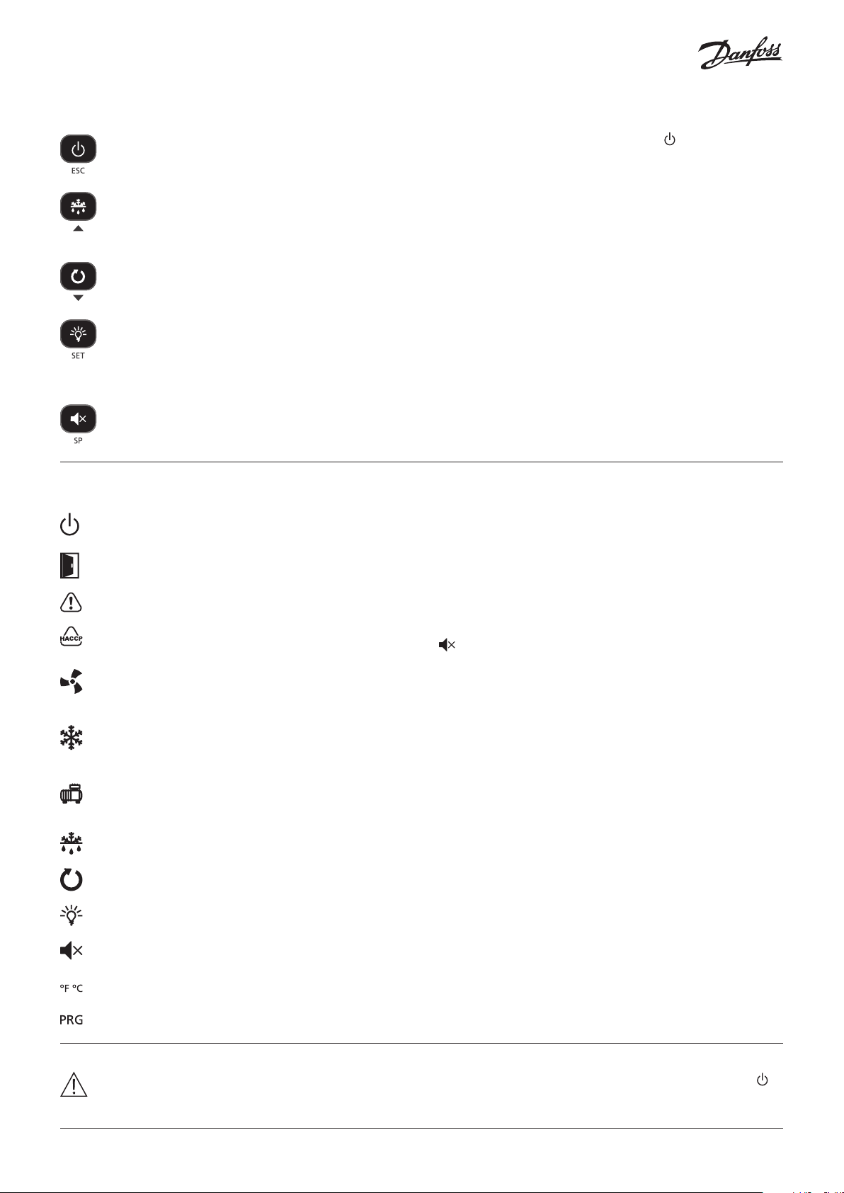
Keypad
Pressing it for 3 seconds activates/deactivates Stand-By mode. In this mode, regulation is paused and the icon is displayed.
In the programming menu, this exits the parameter without saving changes, returns to previous level or exits programming.
Pressing once displays the temperature of probe S2 for 10 seconds (If it is enabled).
Pressing it for 3 seconds starts/stops the defrost.
In the programming menu, this allows scrolling around the different levels, or, during the setting of a parameter, changing its
value.
Pressing it for 3 seconds activates/deactivates continuous cycle mode.
In the programming menu, this allows scrolling around the different levels, or, during the setting of a parameter, changing its
value.
Pressing once activates/deactivates the cold room light.
Pressing it for 3 seconds accesses the condensed programming menu.
Pressing it for 6 seconds accesses the expanded programming menu.
In the programming menu, this accesses the level shown on the display or, during the setting of a parameter, accepts the new
value.
Pressing once displays the current effective value of the Set Point, taking into consideration temporary modifications by other
parameters (C10 or C12).
When an alarm is underway, pressing once mutes the acoustic alarm. Pressing for 3 seconds accesses the Set Point setting.
Indicators
Fixed: Stand-By Mode activated. Regulation is paused.
Flashing: Controlled shutdown process for the regulation underway.
Fixed: Cold room door open.
Flashing: The door has been open for a greater time than has been defined in parameter A12.
There is an active alarm, but not an active HACCP alarm.
Fixed: HACCP alarm active.
Flashing: HACCP alarm registered and unconfirmed. Press the key to confirm an HACCP alarm.
Fixed: Evaporator fans active.
Flashing: The evaporator fans should be active but a delay is preventing this.
(Refer to the Drip time section of the Manual for details).
Fixed: The cold solenoid is active.
Flashing: The solenoid should be active but a delay or protection is preventing this.
(Refer to the Fan start-up section of the Manual for details).
Fixed: Compressor active.
Flashing: The compressor should be active but a delay or protection is preventing this.
(Refer to the Compressor Protection timing section of the Manual for details).
Defrost relay active.
Continuous cycle mode active.
Cold room light active.
Alarm underway muted.
Temperature displayed in ° Fahrenheit / ° Centigrade.
Programming mode active.
STAND-BY
If the temperature regulation cannot be instantly stopped due to its configuration, a controlled stop process starts and the
icon flashes. To stop the controlled stop process and force the step to Stand-by, press the Stand-by key again for 3 seconds.
2 | AN36292867744601-000101
© Danfoss | DCS (vt) | 2021.02
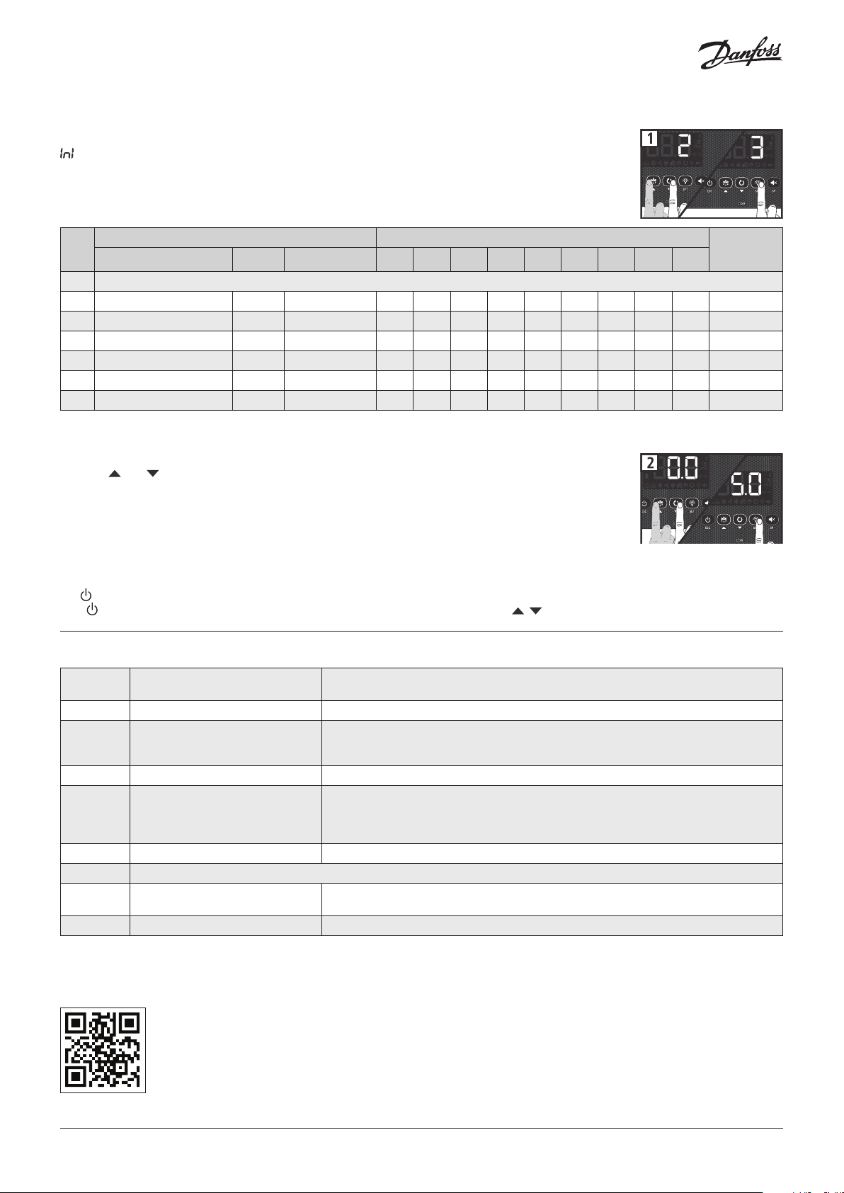
Initial configuration
The first time the unit is powered up, it will enter into the Wizard mode. The display will show the message
flashing with 0.
Step 1:
Select the most suitable InI option based on the type of installation to be carried out and press SET. The
available options will be shown in the following table:
InI
Cold regulation Defrost Evaporator fans o00 I00 I10 I11 I20 I21 d1 d7 F3
0 Demo Mode: it displays the temp. but does not regulate or activate relays
1 Solenoid Electric Yes 0 2 0 0 0 0 20 0 0 A
3 Solenoid + compressor Electric Yes 1 2 0 0 0 0 20 0 0 B
4 Solenoid Air Yes 0 1 0 0 0 0 20 1 1 A
6 Solenoid + compressor Air Yes 1 1 0 0 0 0 20 1 1 B
11 Solenoid Static No 0 1 0 0 0 0 20 1 - A
13 Solenoid + compressor Static No 1 1 0 0 0 0 20 1 - B
Type of installation Parameters
Diagram to
be used
Note: Additional quick set up choices, including hot gas and reversed cycle options are detailed in the User Manual.
Step 2:
Use keys and to enter the desired Temperature Set Point value and press SET. The wizard has finished.
The unit will begin to regulate the temperature.
If this is not the first time you use the wizard, after completing the last step the display will show the
message dFp (default parameters). You may choose between two options:
0: Only parameters included in the wizard will be modified
1: Parameters modified by the wizard will be changed, all other parameters will return to their factory setting.
Important: The wizard will start automatically only on the first power on. To enter the wizard mode, initiate Stand-By mode by pressing
the key for 3 seconds and wait until the unit completely halts the temperature regulation
(The indicator will light up permanently) and press the following keys in sequence, , , SET.
Wizard parameters list
o00 Configuration of relay AUX1
I00 Connected probes 1=Probe 1 (Cold room) 2=Probe 1 (Cold room) + Probe 2 (Evaporator)
I10 Configuration of digital input 1
I11 Polarity of the digital input 1 0=Activates on closing contact 1=Activates on opening contact
I20 Configuration of digital input 2
I21 Polarity of the digital input 2 0=Activates on closing contact 1=Activates on opening contact
d1 Maximum defrost duration (0=defrost deactivated)
d7 Type of defrost
F3 Status of the fans during the defrost 0=Shut down 1=Running
For more details, full User Manual and other information, scan the QR code.
0=Deactivated 1=Compressor/Crankcase heater
2=Light 3=Virtual control
0= Deactivated 1=Door contact 2=External alarm
3=Severe external alarm 4=Change of SP 5=Remote defrost
6=Defrost block 7= Low pressure switch 8=Remote Stand-by
0= Deactivated 1=Door contact 2=External alarm
3=Severe external alarm 4=Change of SP 5=Remote defrost
6=Defrost block 7=Register probe 8=Probe 2° evaporator
9=High pressure switch for Hot Gas 10=Remote Stand-by
0=Resistors 1=Air/fans 2=Hot gas
3=Reversal of cycle
© Danfoss | DCS (vt) | 2021.02
AN36292867744601-000101 | 3
Configuration
Condensed programming menu
Enables the rapid configuration of the most frequently-used parameters (SP, C1, d0, d1, d4, F3, A1 and A2). Press the SET key for 3
seconds to access it.
Extended programming menu
Use the extended programming menu to configure all of the unit’s parameters in order to adapt it to installation requirements. Press the
SET key for 6 seconds to access it.
Important:
• If the function of the password has been configured as a keypad block (b10=2), or as an access block to parameters (b10=1), you
will be requested to enter the access code programmed in PAS when attempting to access either of the two functions. If the entered
password is not correct, the unit will go back to showing the temperature.
• Certain parameters or menus may not be visible depending on the configuration of the rest of the parameters.
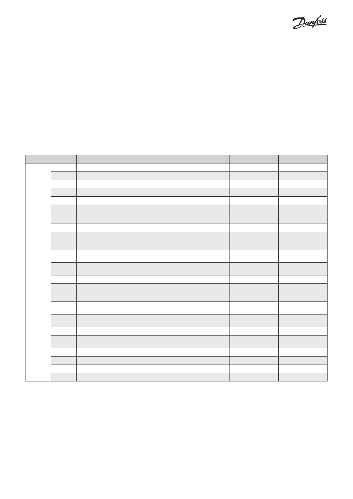
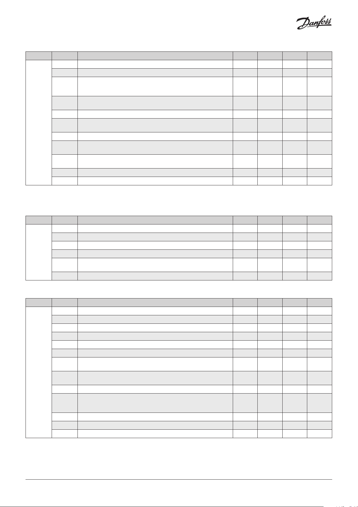
Regulation and control
Level 1 Level 2 Description Values Min. Def. Max.
SP Temperature setting (Set Point) ºF -58 32.0 210
C0 Probe 1 calibration (Offset) ºF -36.0 0.0 36.0
C1 Probe 1 differential (Hysteresis) ºF 0.1 3.6 36
C2 Set Point top locking (it cannot be set above this value) ºF -58 210 210
C3 Set Point bottom locking (it cannot be set below this value) ºF -58 -58 C2
Type of delay for the protection of the compressor:
C4
0=Minimum time of compressor in OFF
1=Minimum time of compressor in OFF and in ON in each cycle
C5 Protection delay time (Value of the option selected in parameter C4) Min. 0 0 120
COOL relay status with fault in probe 1:
C6
0=OFF; 1=ON; 2=Average according to last 24 h prior to probe error
3=ON-OFF according to prog. C7 and C8
Relay time in ON in the event of probe 1 failure
C7
(If C7=0 and C8≠0, the relay will always be disconnected in OFF)
Relay time in OFF in the event of probe 1 failure
C8
rE
C10
C12
C19
C20 Maximum time for pump down (0= deactivated) Min. 0 0 15
C21
C22 Stop fans and compressor on opening door 0=No, 1=Yes 0 0 1
C23 Start-up delay for fans and compressor with door open Min. 0 0 999
C27 Probe 3 calibration (Offset) ºF -36.0 0.0 36.0
(If C8=0 and C7≠0, the relay will always be connected in ON)
C9 Maximum duration of the continuous cycle mode. (0=deactivated) H. 0 0 48
Variation of the Set Point (SP) in continuous cycle mode. When it reaches this point
(SP+C10), it reverts to the normal mode. (SP+C10 ≥ C3).
The value of this parameter is always negative, unless it is 0. (0=OFF)
Variation of the Set Point (SP) when the change Set Point function is active. (SP+C12 ≤
C2) (0= deactivated)
Maximum start time from Pump Down
(Values between 1 and 9 seconds will not be accepted) (0=deactivated)
Probe to be displayed 0=All probes (sequential)
1=Probe 1 (Cold Room), 2=Probe 2 (Evaporator), 3=Probe 3 (According to I20)
EP Exit to level 1
Min. 0 10 120
Min. 0 5 120
ºF 0 -90 C3-SP
ºF C3-SP 0.0 C2-SP
Sec. 0 0 120
0 0 1
0 2 3
0 1 3
4 | AN36292867744601-000101
© Danfoss | DCS (vt) | 2021.02
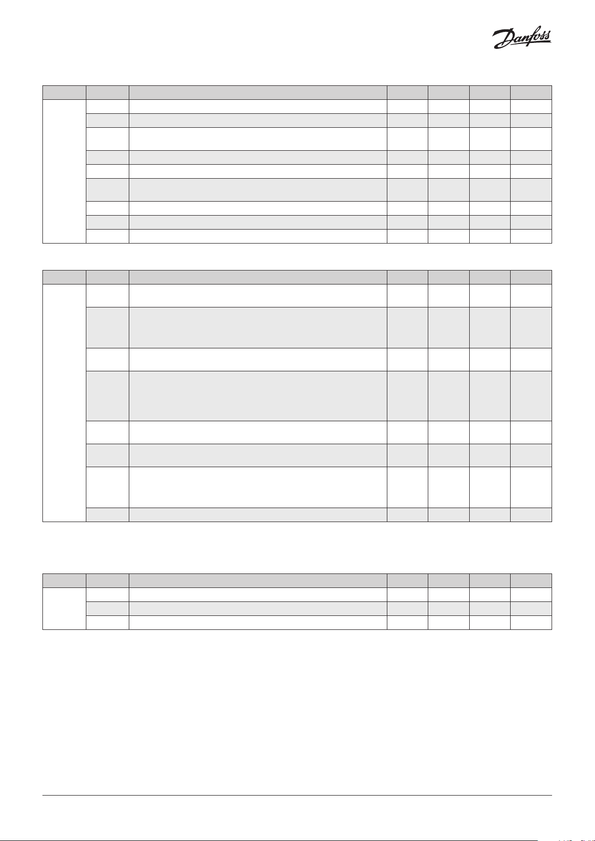
Defrost
Level 1 Level 2 Description Values Min. Def. Max.
d0 Defrost frequency (Time between 2 starts) H. 0 6 96
d1 Maximum defrost duration (0=defrost deactivated) Min. 0 * 255
Type of message during the defrost:
d2
0=Displays the real temperature; 1=Displays the temperature at the start of
the defrost; 2=Displays the dEF message
Maximum duration of the message
d3
(Time added at the end of the defrost process)
d4 Final defrost temperature (by probe) (If I00 ≠ 1) ºF -58 46.4 122
dEF
d7**
* According to wizard.
** It can only be modified using the configuration wizard (InI).
Defrost on connecting the unit:
d5
0=NO First defrost according to d0; 1=YES, First defrost according to d6
d6 Delay of the defrost start on connecting the unit Min. 0 0 255
Type of defrost:
0=Resistors; 1=Air/fans, 2=Hot gas; 3=Reversal of cycle
Count of time between defrost periods:
d8
0=Total real time, 1 =Sum of compressor connected time
d9 Drip time when completing defrost (Shutdown of compressor and fans) Min. 0 1 255
EP Exit to level 1
Min. 0 5 255
0 2 2
0 0 1
0 * 3
0 0 1
Evaporator fans
Level 1 Level 2 Description Values Min. Def. Max.
F0 Shutdown temperature of fans ºF -58 113 122
F1 Probe 2 differential if fans are shut down ºF 0.1 3.6 36
F2 Shut down fans when the compressor shuts down 0=No, 1=Yes 0 0 1
FAn
F3 Status of the fans during the defrost 0=Shut down; 1=Running 0 0 1
Delay of start-up after defrost (If F3=0)
F4
It will only actuate if it is higher than d9
EP Exit to level 1
Min. 0 2 99
Alarms
Level 1 Level 2 Description Values Min. Def. Max.
A0 Configuration of the temperature alarms 0=Relative to SP 1=Absolute 0 1 1
A1 Alarm for maximum in probe 1 (It should be higher than the SP) ºF A2 210 210
A2 Alarm for minimum in probe 1 (It should be lower than the SP) ºF -58 -58 A1
A3 Delay of temperature alarms in the start-up Min. 0 0 120
A4 Delay of temperature alarms from the end of a defrost Min. 0 0 99
A5 Delay of temperature alarms from when the A1 or A2 value is reached 0 30 99
Delay of the external alarm/Severe external alarm on receiving a signal in
AL
A6
digital input (I10 or I20 =2 or 3)
Delay of external alarm deactivation/Severe external alarm deactivation
A7
when the signal in digital input disappears (I10 or I20=2 or 3)
A8 Show warning if the defrost ends for maximum time, 0=No, 1=Yes 0 0 1
Relay alarm polarity
A9
0= Relay ON in alarm (OFF without alarm); 1= Relay OFF in alarm (ON
without alarm)
A10 Differential of temperature alarms (A1 and A2) ºF 0.1 1.8 36
A12 Delay of open door alarm (If I10 or I20=1) Min. 0 10 120
EP Exit to level 1
Min. 0 0 120
Min. 0 0 120
0 0 1
© Danfoss | DCS (vt) | 2021.02
AN36292867744601-000101 | 5
Basic configuration
Level 1 Level 2 Description Values Min. Def. Max.
b00 Delay of all functions on receiving power supply Min. 0 0 255
b01 Cold room light timing Min. 0 0 999
Function of password
0=Inactive, 1=Block access to parameters, 2=Block keypad
Communication speed:
0=9600 bps, 1=19200 bps, 2=38400 bps, 3=57600 bps
EP Exit to level 1
0 0 2
bps 0 0 3
bcn
b10
PAS Access code (Password) 0 0 99
b20 MODBUS address 1 1 247
b21
b22 Acoustic alarm enabled: 0= No, 1=Yes 0 1 1
Unt Work units: 0=ºC, 1=ºF 0 1 1
Inputs and outputs
Level 1 Level 2 Description Values Min. Def. Max.
Connected probes
1=Probe 1 (Cold room), 2=Probe 1 (Cold room) + Probe 2 (Evaporator)
Configuration of digital input 1
0= Deactivated, 1=Door contact, 2=External alarm,
3=Severe external alarm, 4=Change of SP, 5=Remote defrost,
6=Defrost block, 7= Low pressure switch, 8=Remote Stand-by
Polarity of the digital input 1
0=Activates on closing contact; 1=Activates on opening contact
Configuration of digital input 2
0= Deactivated, 1=Door contact, 2=External alarm,
3=Severe external alarm, 4=Change of SP, 5=Remote defrost,
6=Defrost block, 7=Register probe, 8=Probe 2° evaporator,
9=High pressure switch for Hot Gas, 10=Remote Stand-by
Polarity of the digital input 2
0=Activates on closing contact; 1=Activates on opening contact
Configuration of relay AUX1
0=Deactivated, 1=Compressor/Resistor sump, 2=Light, 3=Virtual control
Configuration of relay AUX2
0=Deactivated, 1=Alarm, 2=Light, 3=Virtual control,
4=Door frame resistance, 5=Defrost 2° evaporator,
6=Same as solenoid status, 7=Same as unit status
EP Exit to level 1
1 2 2
0 * 8
0 * 1
0 0 10
0 0 1
0 * 3
0 2 7
In0
I00
I10**
I11
I20
I21
O00**
O10
* According to wizard.
** It can only be modified using the configuration wizard (InI).
HACCP alarm
Level 1 Level 2 Description Values Min. Def. Max.
h1 Maximum temperature of HACCP alarm ºF -58 210 210
HCP
6 | AN36292867744601-000101
h2 Maximum permitted time for activation of the HACCP alarm (0=Disabled) H. 0 0 255
EP Exit to level 1
© Danfoss | DCS (vt) | 2021.02
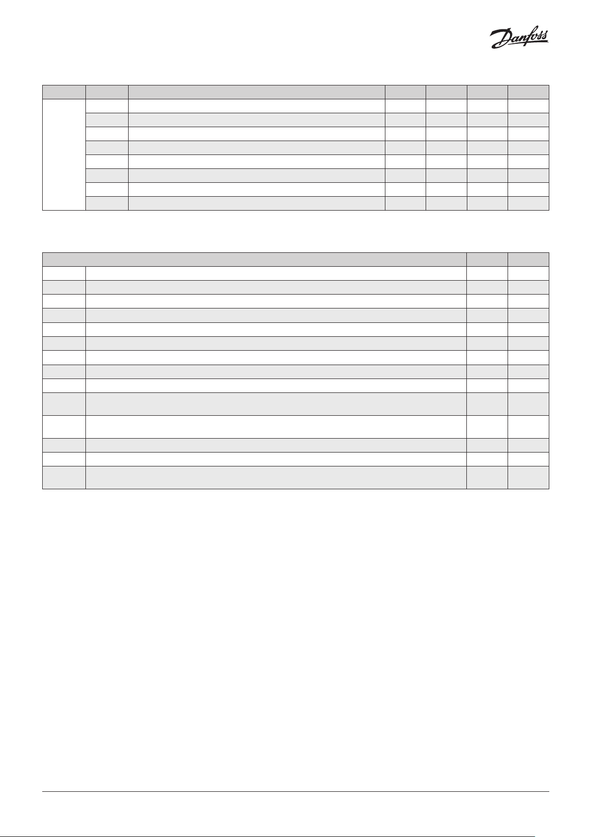
Information (reading only)
Level 1 Level 2 Description Values Min. Def. Max.
InI Option chosen in the configuration wizard
Pd** Pump down active? 0=No, 1=Yes
PU Program version
tid
Pr Program revision
bU Bootloader version
br Bootloader revision
PAr Parameter map revision
EP Exit to level 1
** It can only be modified using the configuration wizard (InI).
Messages
Messages A R
Pd Pump down malfunction error (Shutdown)
LP Pump down malfunction error (Start-up)
E1/E2/E3 Probe 1/2/3 failure (Open circuit, crossed circuit or temperature outside the limits of the probe)
Ad0 Open door alarm. Only if the door stays open for a greater time than is indicated in parameter A12
AH Maximum temperature alarm in control probe. The temperature value programmed in A1 has been reached
AL Minimum temperature alarm in control probe. The temperature value programmed in A2 has been reached
AE External alarm activated (by digital input)
AES Severe external alarm activated (by digital input)
Adt Defrost alarm concluded due to time-out. The time established in d1 has been exceeded
HCP
hCP + PF
dEF Indicates that a defrost is being performed
PAS Access code (Password) request. See parameters b10 and PAS
S1 - S2
A: Activates the acoustic alarm
R: Activates the alarm relay
HACCP alarm. The temperature has reached the value of parameter h1 during a longer period than has been
established in h2
HACCP alarm due to a fault in the power supply. The temperature established in h1 has been reached following a
fault in the power supply
Shown sequentially with the temperature: The controller is in demo mode, the configuration has not been
made.
© Danfoss | DCS (vt) | 2021.02
AN36292867744601-000101 | 7

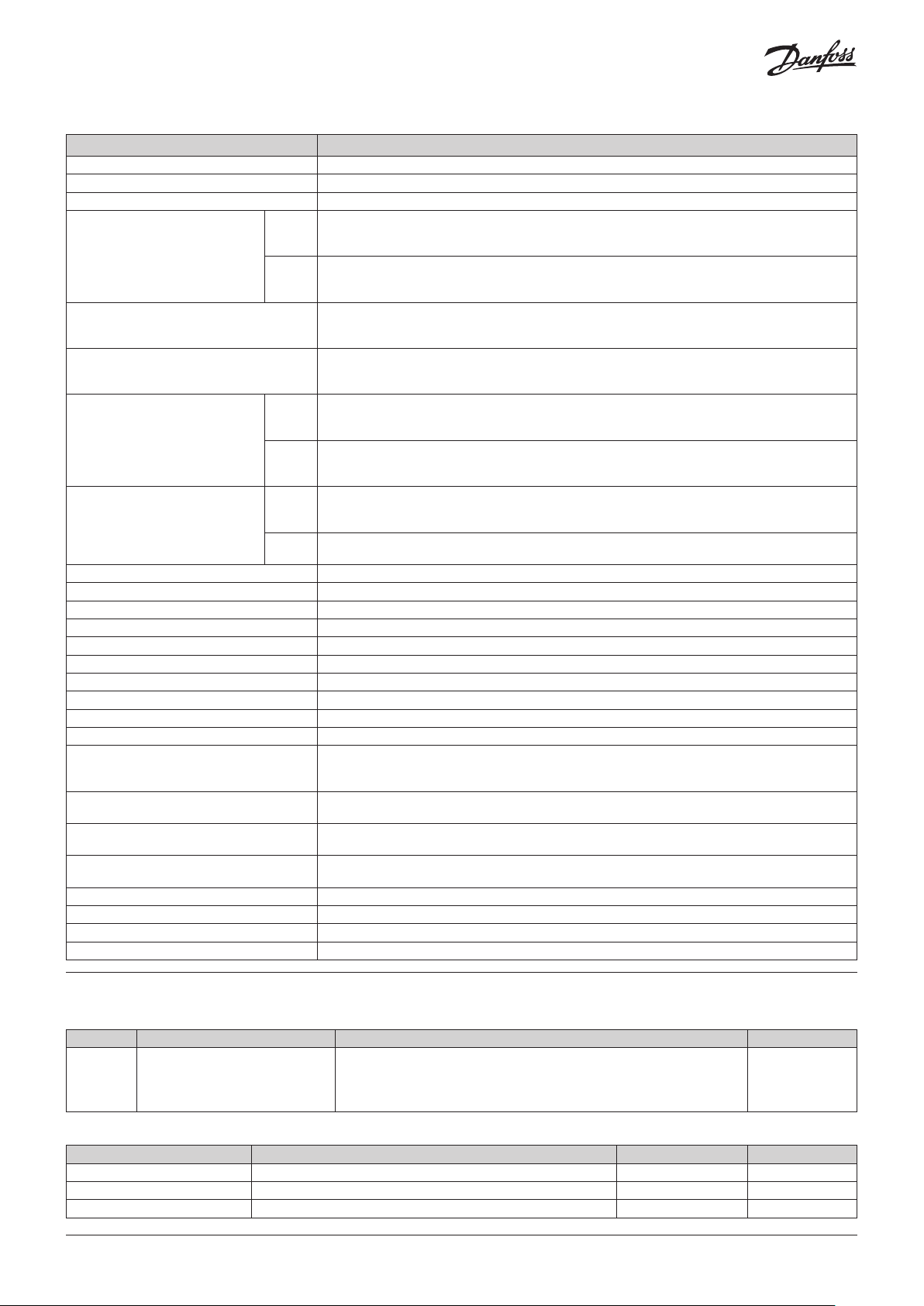
Technical specifications
Features Specifications
Power supply 100 - 240 V~, 50 - 60 Hz
Maximum input power in the operation 8.1 VA
Maximum nominal current 15 A
NO
Relay DEFROST - SPDT - 20 A
NC
Relay FAN - SPST - 16 A
Relay COOL - SPST - 16 A
NO
Relay AUX 1 - SPDT - 20 A
NC
NO
Relay AUX 2 - SPDT - 16 A
NC
No. of relay operations EN60730-1:100.000 operations
Probe temperature range -58 – 211 ºF
Resolution, setting and differential 0.2 ºF
Thermometric precision ±1.8 ºF
Loading tolerance of the NTC probe at 25 °C ±0.7 ºF
Working ambient temperature 14 – 122 ºF
Storage ambient temperature -22 – +140 ºF
Protection degree IP 40 (IP 65 installing the proper glands)
Pollution degree II acc. UL 60730-1
Construction Independently mounted acc. UL 60730-1
Control device classification
Temperature during ball-pressure test
Current of radio jamming suppression tests 270 mA
Voltage and current as per EMC tests 207 V, 17 mA
Type of assembly Fixed internal
MODBUS address Shown on label
Dimensions 11.42 in (W) x 5.55 in (H) x 3.32 in (D)
Internal buzzer
EN60730-1: 15 (15) A 250 V~
UL-60730: 9 FLA 54 LRA, 240 V AC
UL-60730: RES 12 A, 240 V AC)
EN60730-1: 15 (13) A 250 V~
UL-60730: 6 FLA 36 LRA, 240 V AC
UL-60730: RES 6 A, 240 V AC
EN60730-1: 12 (9) A 250 V~
UL-60730: 5 FLA 30 LRA, 240 V AC
UL-60730: RES 10 A, 240 V AC
EN60730-1: 12 (9) A 250 V~
UL-60730: 5 FLA 30 LRA, 240 V AC
UL-60730: RES 10 A, 240 V AC)
EN60730-1: 15 (15) A 250 V~
UL-60730: 9 FLA 54 LRA, 240 V AC
UL-60730: RES 12 A, 240 V AC
EN60730-1: 15 (13) A 250 V~
UL-60730: 6 FLA 36 LRA, 240 V AC
UL-60730: RES 6A, 240 V AC
EN60730-1: 12 (9) A 250 V~
UL-60730: 5 FLA 30 LRA, 240 V AC
UL-60730: RES 10 A, 240 V AC
EN60730-1: 10 (8) A 250 V~
UL-60730: 5A, 240 V AC
Built-in assembly, with Type 1.B automatic operation action feature, for use in clean situations,
logical support (Software) class A and continuous operation.
Double isolation between power supply, secondary circuit and relay output.
Accessible parts: 167 ºF
Parts which position active elements: 257 ºF
Ordering
Controller
Model Description Comments Code no.
Includes:
AK-RC 251 AK-RC 251 Gen. 2,5 O/P, Single phase
Accessories (for spares and replacement purposes):
Name Features Qty Code no.
3.5 m, NTC 10K Sensor Thermo plastic rubber probe 1 084N3210
8.5 m, NTC 10K sensor Thermo plastic rubber probe 50 084N3208
1.5 m, NTC 10K sensor Stainless steel probe 150 084N3200
8 | AN36292867744601-000101
• 1 x 1.5 m, NTC 10K sensor
• 1 x 3 m, NTC 10K sensor
• 2 x 2 caps to provide IP65 protection after installation
080Z5000
© Danfoss | DCS (vt) | 2021.02
ESPAÑOL
Advertencias
• Utilizar el controlador sin respetar las instrucciones del fabricante, puede alterar los requisitos de seguridad del enfriador. Para el
funcionamiento correcto del mismo sólo deberán utilizarse sensores de temperatura tipo NTC suministrados por Danfoss.
• Entre –40 ºF y +68 ºF, si el sensor de temperatura NTC es colocado hasta 1.000m de distancia con cable de calibre mínimo 20AWG, la
desviación de temperatura máxima esperada será de 0.45 ºF.
• Debe ser instalado en un sitio protegido de vibraciones, agua y de gases o liquidos corrosivos, donde la temperatura ambiente no
supere el valor reflejado en los datos técnicos.
• Para que la lectura sea correcta, el sensor de temperatura debe ubicarse en un sitio sin influencias térmicas ajenas a la temperatura
que se desea medir o controlar.
• El grado de protección IP65 solo es válido con la tapa protectora cerrada.
• El grado de protección IP65 sólo es válido si la entrada de cables al equipo se realiza mediante tubo para conducciones eléctricas +
conector con IP65 o superior. El tamaño de los conectores debe ser el adecuado para el diámetro de tubo utilizado.
• No rociar directamente el equipo con mangueras de alta presión, pues esto puede causar daño.
IMPORTANTE:
• Antes de iniciar la instalación, debe tener en cuenta las normas locales vigentes.
• Los relés AUXILIARES son programables y su funcionamiento depende de la configuración.
• La función de las entradas digitales depende de la configuración.
• Los voltajes y consumo de corriente indicados son los valores máximos de trabajo permitidos.
Cableado
Desconectar siempre la alimentación eléctrica antes de realizar el cableado.
Los sensores de temperatura NUNCA deben instalarse junto con cables de potencia, control o alimentación.
El circuito de alimentación debe estar provisto de un interruptor para su desconexión de mínimo 2 A, 230 V, situado cerca del aparato. El
cable de alimentación será del tipo H05VV-F o NYM 1x16/3. La sección a utilizar dependerá de las normas locales vigentes, pero nunca
deberá ser inferior a 14AWG.
Los cables para las salidas de los relevadores o contactores deben ser mínimo 14AWG, deben admitir temperaturas de trabajo iguales o
superiores a 158 ºF y se deben instalar con el menor número de dobleces.
La zona de conexión a 120 / 230 V debe mantenerse despejada de cualquier elemento externo.
La conexión a realizar depende del tipo de instalación. Utilice el diagrama eléctrico adecuado en función de la opción escogida en el
asistente. Consulte las opciones disponibles en la hoja de diagramas eléctricos incluido con el control.
Mantenimiento
• Limpie la superficie del equipo con un paño suave, agua y jabón.
• No utilice detergentes abrasivos, gasolina, alcohol o disolventes, esto puede dañar el controlador.
© Danfoss | DCS (vt) | 2021.02
AN36292867744601-000101 | 9

Teclado
Presionar este botón durante 3 segundos, activa / desactiva el modo Stand-By. En este modo la regulación se detiene y el
display muestra el icono .
En el menú de programación, este botón sale del parámetro sin guardar cambios, retrocede al nivel anterior o sale de la
programación.
Presionar el botón una vez muestra la temperatura del sensor S2 durante 10 segundos (Si está disponible).
Pulsando durante 3 segundos, inicia / detiene el deshielo.
En el menú de programación, permite moverse por los diferentes niveles, o, durante el ajuste de un parámetro, permite cambiar
el valor del mismo.
Presionar este botón durante 3 segundos, activa / desactiva el modo ciclo continuo.
En el menú de programación, permite moverse por los diferentes niveles, o, durante el ajuste de un parámetro permite cambiar
el valor del mismo.
Presionar el botón una vez activa / desactiva la luz del cuarto frio.
Presionar este botón durante 3 segundos, accede al menú de programación reducido.
Presionar este botón durante 6 segundos, accede al menú de programación extendido.
En el menú de programación, accede al nivel mostrado en pantalla o, durante el ajuste de un parámetro, acepta y graba el
nuevo valor.
Presionar el botón una vez muestra el valor efectivo actual del Set Point de temperatura, teniendo en cuenta las modificaciones
temporales hechas por otros parámetros (C10 ó C12).
Si existe una alarma en curso, presionar el botón una vez silenciara la alarma acústica. Presionar este botón durante 3 segundos,
accede al ajuste del Set Point de temperatura.
Indicadores
Fijo: Modo Stand-By activo, el control del cuarto frío esta detenido.
Intermitente: Proceso de paro controlado de la regulación en curso.
Fijo: Puerta abierta.
Intermitente: La puerta lleva abierta un tiempo superior al definido en el parámetro A12.
Hay una alarma activa, pero no de tipo HACCP.
Fijo: Alarma HACCP activa.
Intermitente: Alarma de HACCP registrada y sin confirmar. Para confirmar una alarma HACCP, pulsar la tecla
Fijo: Ventiladores de evaporador activos.
Intermitente: Los ventiladores de evaporador deberían estar activos pero algún retardo se lo impide
(ver la sección de tiempo de goteo en el manual para mas detalles).
Fijo: La válvula solenoide esta activa.
Intermitente: La válvula solenoide debería estar activa pero algún retardo o protección se lo impide
(ver la sección de arranque de abanicos en el manual para más detalles).
Fijo: Compresor activo.
Intermitente: El compresor debería estar activo pero algún retraso o protección se lo impide
(ver la sección de tiempo de protección del compresor en el manual para más detalles).
Relevador de deshielo activo.
Modo ciclo continuo activo.
Luz del cuarto frio activa.
Alarma en curso silenciada.
Temperatura indicada en ° Fahrenheit / ° Centígrados.
Modo de programación activo.
STAND-BY
Si la regulación de temperatura no puede detenerse inmediatamente debido a la configuración de la instalación, como por
ejemplo, en el caso de Pump Down, se inicia un proceso de paro controlado y el icono parpadea. Para detener el proceso de
paro controlado y forzar el paso a Stand-by, presionar la tecla Stand-by nuevamente durante 3 segundos.
10 | AN36292867744601-000101
© Danfoss | DCS (vt) | 2021.02

Configuración inicial (Asistente)
Al conectarse por primera vez, el controlador entra en modo ASISTENTE. El display muestra el mensaje
intermitente con 0.
Paso 1:
Seleccionar la opción InI adecuada según el tipo de instalación a realizar y presionar SET. Las opciones
básicas disponibles se muestran en la siguiente tabla:
Tipo de instalación Parámetros
InI
Regulación del frío Deshielo
0 Modo demo, muestra temperatura en pantalla pero no regula temperatura ni activa relevadores.
1 Solenoide Eléctrico Si 0 2 0 0 0 0 20 0 0 A
3 Solenoide + compresor Eléctrico Si 1 2 0 0 0 0 20 0 0 B
4 Solenoide Aire Si 0 1 0 0 0 0 20 1 1 A
6 Solenoide + compresor Aire Si 1 1 0 0 0 0 20 1 1 B
11 Solenoide Estático No 0 1 0 0 0 0 20 1 - A
13 Solenoide + compresor Estático No 1 1 0 0 0 0 20 1 - B
Ventiladores
evaporador
o00 I00 I10 I11 I20 I21 d1 d7 F3
Diagramma
a utilizar
Nota: Otros programas de instalación rápida adicionales, incluyendo programas para gas caliente y ciclo invertido se detallan en el
manual de usuario. Ver Manual de Usuario para detalles.
Paso 2:
Introducir el valor de ajuste de temperatura (Set Point) deseado mediante las teclas , y pulsar SET. El
asistente de configuración ha finalizado, el equipo comienza a regular la temperatura.
Si no es la primera vez que se ejecuta el asistente, al finalizar el último paso, el display muestra el mensaje
dFp (parametros por defecto) pudiendo elegir entre dos opciones:
0: Sólo modificar los parámetros incluidos en el asistente.
1: Los parámetros modificados por el asistente se cambian y todos los demás parámetros retornan a su valor
de fábrica.
IMPORTANTE: El asistente de configuración se activa solamente cuando el controlador se conecta por primera vez. Para activarlo de
nuevo, se debe activar el modo Stand-By presionando el botón durante 3 segundos y esperar a que el equipo detenga la regulación
completamente (El indicador se ilumina de forma permanente) y a continuación pulsar en este orden las botones: , , SET.
Lista de parámetros del Asistente
o00 Configuración de relevador AUX1
I00 Sensores conectados 1=Sensor 1 (Cuarto frio) 2=Sensor 1 (Cuarto frio) + Sensor 2 (Evaporador)
I10 Configuración de entrada digital 1
I11 Polaridad de la entrada digital 1 0=Activa en contacto cerrado 1=Activa en contacto abierto
I20 Configuración de entrada digital 2
I21 Polaridad de la entrada digital 2 0=Activa en contacto cerrado 1=Activa en contacto abierto
d1 Duración máxima de deshielo (0=deshielo desactivado)
d7 Tipo de deshielo
F3
Estado de los abanicos durante el
deshielo
Para más información, incluyendo el Manual de Usuario,
use el código QR para acceder a la página de soporte.
0=Desactivado 1=Compresor/Resistencia al cárter
2=Luces 3=Control virtual
0=Desactivada 1=Contacto de puerta 2=Alarma externa
3=Alarma externa severa 4=Cambio de SP 5=Deshielo remoto
6=Bloqueo de deshielo 7=Switch de baja presión 8=Stand-by remoto
0=Desactivada 1=Contacto de puerta 2=Alarma externa
3=Alarma externa severa 4=Cambio de SP 5=Deshielo remoto
6=Bloqueo de deshielo 7=Registrar sensor 8=2° Sensor de evaporador
9=
Switch de alta presión para gas caliente
0=Resistencias 1=Aire/abanicos 2=Gas caliente
3=Ciclo invertido
0=Apagados 1=Encendidos
10=Stand-by remoto
© Danfoss | DCS (vt) | 2021.02
AN36292867744601-000101 | 11

Configuración
Menú de programación reducido
Permite configurar rápidamente los parámetros más utilizados (SP, C1, d0, d1, d4, F3, A1 y A2). Para acceder, presionar el botón SET
durante 3 segundos.
Menú de programación extendido
Mediante el menú de programación extendido, podrá configurar todos los parámetros del equipo para adaptarlo a las necesidades de su
instalación. Para acceder, presionar el botón SET durante 6 segundos.
Importante:
• Si se ha configurado la función del código de acceso como bloqueo del teclado (b10=2), o como bloqueo acceso a parámetros
(b10=1) al intentar acceder a cualquiera de las dos funciones, se solicitará la introducción del código de acceso programado en PAS. Si
el código introducido no es correcto, el equipo volverá a mostrar la temperatura.
• Determinados parámetros o menús pueden no ser visibles dependiendo de la configuración del resto de parámetros.
Regulación y control
Nivel 1 Nivel 2 Descripción Valores Min. Def. Max.
SP Ajuste de temperatura (Set Point) ºF -58 32.0 210
C0 Calibración del sensor 1 (Offset) ºF -36.0 0.0 36.0
C1 Diferencial del sensor 1 (Histéresis) ºF 0.1 3.6 36
C2
C3
C4
C5
rE
C10
C12
C19
C20 Tiempo máximo para el Pump Down (0=desactivado) Min. 0 0 15
C21
C22 Detener ventiladores y compresor al abrir puerta, 0=No, 1=Si 0 0 1
C23 Retraso de arranque de ventiladores y compresor con puerta abierta Min. 0 0 999
C27 Calibración del sensor 3 (Offset) ºF -36.0 0.0 36.0
Bloqueo de límite superior de ajuste (no se podrá fijar temperatura por
encima de este valor)
Bloqueo de límite inferior de ajuste (no se podrá fijar temperatura por
debajo de este valor)
ºF -58 210 210
ºF -58 -58 C2
Tipo de retraso para protección del compresor:
0=Tiempo mínimo del compresor en OFF
0 0 1
1=Tiempo mínimo del compresor en OFF y en ON en cada ciclo
Tiempo de retraso de la protección (Valor de la opción elegida en
parámetro C4)
Estado del relevador COOL con fallo en el sensor 1:
C6
0=OFF; 1=ON; 2=promedio de las últimas 24h previas al error del sensor
3=ON-OFF según prog. C7 y C8
Tiempo del relevador en ON en caso de sensor 1 dañado
C7
(Si C7=0 y C8≠0, el relé estará siempre en OFF desconectado)
Tiempo del relevador en OFF en caso de sensor 1 dañado
C8
(Si C8=0 y C7≠0, el relevador estará siempre conectado en ON)
C9 Duración máxima del modo de ciclo continuo. (0=desactivado) H. 0 0 48
Variación del ajuste de temperatura (SP) en modo de ciclo continuo, una vez llegado a
este punto (SP+C10), vuelve al modo normal. (SP+C10 ≥ C3).
El valor de este parámetro es siempre negativo, excepto si es 0. (0=OFF)
Variación del ajuste de temperatura (SP) cuando la función cambio de Set point está
activa. (SP+C12 ≤ C2) (0= desactivado)
Tiempo máximo para arranque desde el inicio del Pump Down (No se aceptan valores
entre 1 y 9 segundos) (0=desactivado)
Sensor a visualizar
0=Todas los sensores (secuencial), 1=Sensor 1 (Cuarto frio), 2=Sensor 2 (Evaporador),
3=Sensor 3 (Según I20)
EP Salida a nivel 1
Min. 0 0 120
0 2 3
Min. 0 10 120
Min. 0 5 120
ºF 0 -90 C3-SP
ºF C3-SP 0.0 C2-SP
Sec. 0 0 120
0 1 3
12 | AN36292867744601-000101
© Danfoss | DCS (vt) | 2021.02

Deshielo
Nivel 1 Nivel 2 Descripción Valores Min. Def. Max.
d0 Frecuencia de deshielo (Tiempo entre 2 inicios) H. 0 6 96
d1 Duración máxima del deshielo (0=deshielo desactivado) Min. 0 * 255
d2
d3
d4 Temperatura final de deshielo (por sensor ) (Si I00 ≠ 1) ºF -58 46.4 122
dEF
* Según asistente de configuración.
** Solo se puede modificar mediante el asistente de configuración (InI).
d5
d7**
d8
d9 Tiempo de goteo al finalizar un deshielo (Paro de compresor y ventiladores) Min. 0 1 255
Mensaje durante el deshielo:
0=Muestra la temperatura real; 1=Muestra la temperatura al inicio del
deshielo; 2=Muestra el mensaje dEF
Duración máxima del mensaje
(Tiempo añadido al final del proceso de deshielo)
Deshielo al conectar el equipo:
0=NO Primer deshielo según d0; 1=SI, Primer deshielo según d6
d Retraso de inicio del deshielo al conectar el equipo Min. 0 0 255
Tipo de deshielo:
0=Resistencias; 1=Aire / ventiladores; 2=Hot gas; 3=Ciclo invertido
Cuenta de tiempo entre períodos de deshielo:
0=Tiempo real total, 1=Suma de tiempo del compresor conectado
EP Salida a nivel 1
Min. 0 5 255
0 2 2
0 0 1
0 * 3
0 0 1
Ventiladores de evaporador
Nivel 1 Nivel 2 Descripción Valores Min. Def. Max.
F0 Temperatura de paro de los ventiladores ºF -58 113 122
F1 Diferencial del sensor 2 si los ventiladores están parados ºF 0.1 3.6 36
F2 Detener ventiladores al parar compresor, 0=No, 1=Si 0 0 1
FAn
F3 Estado de los ventiladores durante el deshielo, 0=Parados, 1=Encendidos 0 0 1
Retraso de arranque después del deshielo (Si F3=0)
F4
Solo se activa si es superior a d9
EP Salida a nivel 1
Min. 0 2 99
Alarmas
Nivel 1 Nivel 2 Descripción Valores Min. Def. Max.
A0 Configuración de las alarmas de temperatura 0=Relativa al SP, 1=Absoluta 0 1 1
A1 Alarma de máxima de temperatura en sensor 1 (Debe ser mayor que el SP) ºF A2 210 210
A2 Alarma de mínima de temperatura en sensor 1 (Debe ser menor que el SP) ºF -58 -58 A1
A3 Retraso de alarmas de temperatura en el arranque Min. 0 0 120
A4 Retraso de alarmas de temperatura después de finalizado el deshielo Min. 0 0 99
A5 Retraso de alarmas de temperatura cuando se alcanza el valor de A1 o A2 0 30 99
A6
AL
A7
A8 Mostrar advertencia si el deshielo finaliza por tiempo máximo, 0=No, 1=Si 0 0 1
A9
A10 Diferencial de alarmas de temperatura (A1 y A2) ºF 0.1 1.8 36
A12 Retraso de alarma de puerta abierta (Si I10 ó I20=1) Min. 0 10 120
Retraso de alarma externa / Alarma externa severa al recibir señal en la
entrada digital (I10 ó I20 =2 ó 3)
Retraso de desactivación de alarma externa / Alarma externa severa al
desaparecer la señal en la entrada digital (I10 ó I20=2 ó 3)
Polaridad del relevador alarma
0= Relevador ON en alarma (OFF sin alarma); 1= Relevador OFF en alarma
(ON sin alarma)
EP Salida a nivel 1
Min. 0 0 120
Min. 0 0 120
0 0 1
© Danfoss | DCS (vt) | 2021.02
AN36292867744601-000101 | 13

Configuración básica
Nivel 1 Nivel 2 Descripción Valores Min. Def. Max.
b00 Retraso de todas las funciones al recibir el voltaje de alimentación Min. 0 0 255
b01 Temporizador de la luz del cuarto frio Min. 0 0 999
Función del código de acceso (Password)
0=Inactivo, 1=Bloqueo de acceso a parámetros, 2=Bloqueo del teclado
Velocidad de comunicación:
0=9600 bps, 1=19200 bps, 2=38400 bps, 3=57600 bps
EP Salida a nivel 1
0 0 2
bps 0 0 3
bcn
b10
PAS Código de acceso (Password) 0 0 99
b20 Dirección MODBUS 1 1 247
b21
b22 Alarma acústica habilitada: 0= No, 1=Si 0 1 1
Unt Work units: 0=ºC, 1=ºF 0 1 1
Entradas y salidas
Nivel 1 Nivel 2 Descripción Valores Min. Def. Max.
I00
I10**
I11
I20
In0
I21
O00**
O10
* Según asistente de configuración.
** Solo se puede modificar mediante el asistente de configuración (InI).
Sensores conectados
1=Sensor 1 (Cámara), 2=Sensor 1 (Cámara) + Sensor 2 (Evaporador)
Configuración de la entrada digital 1
0=Desactivada, 1=Contacto de puerta, 2=Alarma externa,
3=Alarma externa severa, 4=Cambio de SP, 5=Deshielo remoto,
6=Bloqueo de deshielo, 7=Switch de baja presión, 8=Stand-by remoto
Polaridad de la entrada digital 1
0=Activa en contacto cerrado; 1=Activa en contacto abierto
Configuración de la entrada digital 2
0=Desactivada, 1=Contacto puerta, 2=Alarma externa,
3=Alarma externa severa, 4=Cambio de SP, 5=Desescarche remoto,
6=Bloqueo de deshielo, 7=Registrar sensor, 8=2º Sensor de evaporador,
9=Switch de alta presion para gas caliente, 10=Stand-by remoto
Polaridad de la entrada digital 2
0=Activa en contacto cerrado; 1=Activa en contacto abierto
Configuración del relevador AUX1
0=Desactivado, 1=Compresor/Resistencia al cárter, 2=Luz, 3=Control
virtual
Configuración del relevador AUX2
0=Desactivado, 1=Alarma, 2=Luz, 3=Control virtual, 4=Resistencia
del marco de puerta, 5=Deshielo de 2º evaporador, 6=Acción Igual al
solenoide, 7=Acción igual al estado del equipo
EP Salida a nivel 1
1 2 2
0 * 8
0 * 1
0 0 10
0 0 1
0 * 3
0 2 7
Alarma HACCP
Nivel 1 Nivel 2 Descripción Valores Min. Def. Max.
h1 Temperatura máxima para alarma HACCP ºF -58 210 210
HCP
h2
14 | AN36292867744601-000101
Tiempo máximo permitido para activación de alarma HACCP
(0=Deshabilitada)
EP Salida a nivel 1
H. 0 0 255
© Danfoss | DCS (vt) | 2021.02

Información (Solo lectura)
Nivel 1 Nivel 2 Descripción Valores Min. Def. Max.
InI Opción escogida en el asistente de configuración
Pd** Pump Down activo? 0=No, 1=Si
PU Versión de programa
tid
** Solo se puede modificar mediante el asistente de configuración (InI).
Pr Revisión de programa
bU Versión de bootloader
br Revisión de bootloader
PAr Revisión de mapa de parámetros
EP Salida a nivel 1
Mensajes
Mensajes A R
Pd Error de funcionamiento del Pump Down (Paro)
LP Error de funcionamiento del Pump Down (Arranque)
E1/E2/E3 Sensores 1/2/3 dañados (Circuito abierto, cruzado, o temperatura fuera de los límites del sensor)
Ad0 Alarma de puerta abierta. Sólo si la puerta permanece abierta un tiempo superior al indicado en el parámetro A12
AH Alarma de temperatura máxima en sensor de control. Se ha alcanzado el valor de temperatura programado en A1
AL Alarma de temperatura mínima en sensor de control. Se ha alcanzado el valor de temperatura programado en A2
AE Alarma externa activada (por entrada digital)
AES Alarma externa severa activada (por entrada digital)
Adt Alarma de deseshielo finalizado por tiempo, se ha superado el tiempo definido en d1
HCP
hCP + PF
dEF Indica que se está efectuando un deshielo
PAS Petición de código de acceso (Password). Ver parámetros b10 y PAS
S1 - S2
A: Activa la alarma acústica
R: Activa el relé de alarma
Alarma HACCP, la temperatura ha alcanzado el valor del parámetro h1 durante un tiempo superior al definido en
h2
Alarma HACCP por fallo en el suministro eléctrico, se ha alcanzado la temperatura definida en h1 después de un
fallo en el suministro eléctrico
Mostrados de forma secuencial con la temperatura: El controlador está en modo demo, la configuración no se
ha realizado
© Danfoss | DCS (vt) | 2021.02
AN36292867744601-000101 | 15
Especificaciones técnicas
Caracteristicas Especificaciones
Alimentación 100 - 240 V~, 50 - 60 Hz
Consumo de potencia máximo 8.1 VA
Corriente nominal máxima 15 A
NO
Relevador DEFROST - SPDT - 20 A
NC
Relevador FAN - SPST - 16 A
Relevador OOL - SPST - 16 A
NO
Relevador AUX 1 - SPDT - 20 A
NC
NO
Relevador AUX 2 - SPDT - 16 A
NC
Nº de operaciones de los relevadoress EN60730-1:100.000 operaciones
Rango de temperatura del sensor -58 – 211 ºF
Resolución, ajuste y diferencial 0.2 ºF
Precisión termométrica ±1.8 ºF
Tolerancia del sensor NTC a 25 ºC ±0.7 ºF
Temperatura ambiente de trabajo 14 – 122 ºF
Temperatura ambiente de almacenaje -22 – +140 ºF
Grado de protección IP 40 (IP65 Cuando se instala con los sellos correspondientes)
Grado de polución s/ UL 60730-1
Construcción De montaje independiente s/ UL 60730-1
Clasificación
Temperatura del ensayo de la bola de presión
Corriente de ensayo de supresión de
radiointerferencias
Tensión y corriente declarados por los ensayos
de EMC
Tipo de montaje Interior fijo
Dirección MODBUS Indicada en la etiqueta
Dimensiones 11.42 in (An) x 5.55 in (Al) x 3.32 in (P)
Zumbador interno
EN60730-1: 15 (15) A 250 V~
UL-60730: 9 FLA 54 LRA, 240 V AC
UL-60730: RES 12 A, 240 V AC)
EN60730-1: 15 (13) A 250 V~
UL-60730: 6 FLA 36 LRA, 240 V AC
UL-60730: RES 6 A, 240 V AC
EN60730-1: 12 (9) A 250 V~
UL-60730: 5 FLA 30 LRA, 240 V AC
UL-60730: RES 10 A, 240 V AC
EN60730-1: 12 (9) A 250 V~
UL-60730: 5 FLA 30 LRA, 240 V AC
UL-60730: RES 10 A, 240 V AC)
EN60730-1: 15 (15) A 250 V~
UL-60730: 9 FLA 54 LRA, 240 V AC
UL-60730: RES 12 A, 240 V AC
EN60730-1: 15 (13) A 250 V~
UL-60730: 6 FLA 36 LRA, 240 V AC
UL-60730: RES 6A, 240 V AC
EN60730-1: 12 (9) A 250 V~
UL-60730: 5 FLA 30 LRA, 240 V AC
UL-60730: RES 10 A, 240 V AC
EN60730-1: 10 (8) A 250 V~
UL-60730: 5A, 240 V AC
Dispositivo de control incorporado, de característica de funcionamiento automático acción Tipo 1.B,
para utilización en situación limpia, soporte lógico (software) clase A y funcionamiento contínuo.
Aislamiento doble entre alimentación, circuito secundario y salida relé.
Partes accesibles: 167 ºF
Partes que posicionan elementos activos: 257 ºF
270 mA
207 V, 17 mA
Pedidos
Controlador
Modelo Descripción Comentarios Código
Incluye:
AK-RC 251 AK-RC 251 Gen. 2,5 O/P, Monofásico
Accesorios (para partes de repuesto y expansión):
Nombre Detalles Cantidad Código
3.5 m, NTC 10K Sensor Sensor de Goma termoplástica 1 084N3210
8.5 m, NTC 10K sensor Sensor de Goma termoplástica 50 084N3208
1.5 m, NTC 10K sensor Sensor de acero inoxidable 150 084N3200
16 | AN36292867744601-000101
• 1 x 1.5 m, NTC 10K sensor
• 1 x 3 m, NTC 10K sensor
• Tapas de 2 x 2 para proporcionar protección IP65 después de la instalación
© Danfoss | DCS (vt) | 2021.02
080Z5000
 Loading...