

Page 1
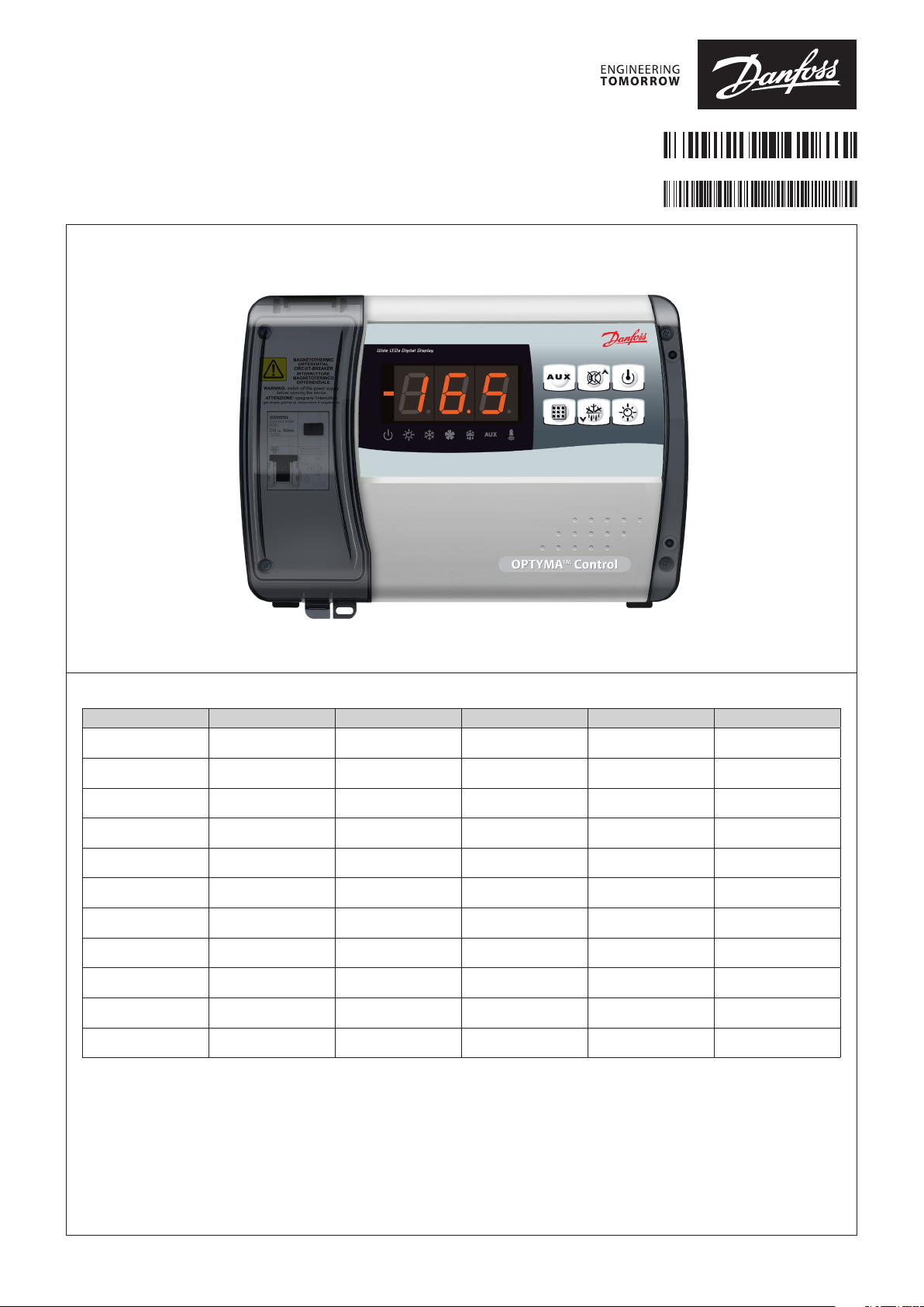
Installation Guide
Optyma™ control
080R9290
AK-RC 111, AK-RC 113
AN30923034432301-000102
English Nederlands Deutsch Français Español Italiano
Compressor protection Kriwan Kriwan Kriwan Kriwan Protezione compressore
Door limit switch Deurschakelaar Tür Porte Puerta Micro porta
Ambient probe Ruimtesensor Raumfühler Température ambiente Temperatura ambiente Sonda ambiente
Defrost probe Ontdooisensor Abtaufühler Sonde de dégivrage Sensor de desescarche Sonda evaporatore
RS485 Modbus RS485 Modbus RS485 Modbus RS485 Modbus RS485 Modbus RS485 Modbus
Supply 230 V AC Voeding 230 V AC Versorgung 230 V AC Alimentation 230 V AC Suministro 230 V AC Alimentazione 230 V AC
Defrost heater Ontdooiing Abtauheizungen Résistances de dégivrage
Evaporator fans Verdamperventilator Verdampferlüfter Ventilateur évaporateur Evaporador ventilador Ventole evaporatore
Compressor Compressor Kompressor Compresseur Compresor Compressore
Light Verlichting Licht Éclairage Iluminación Luce
Alarm / Aux Alarm / Aux Alarm / Aux Alarme / Aux Alarma / Aux Allarme / Aux
Resistencias de
descongelación
Resistenze sbrinamento
© Danfoss | DCS (vt) | 2020.05
AN30923034432301-000102 | 1
Page 2
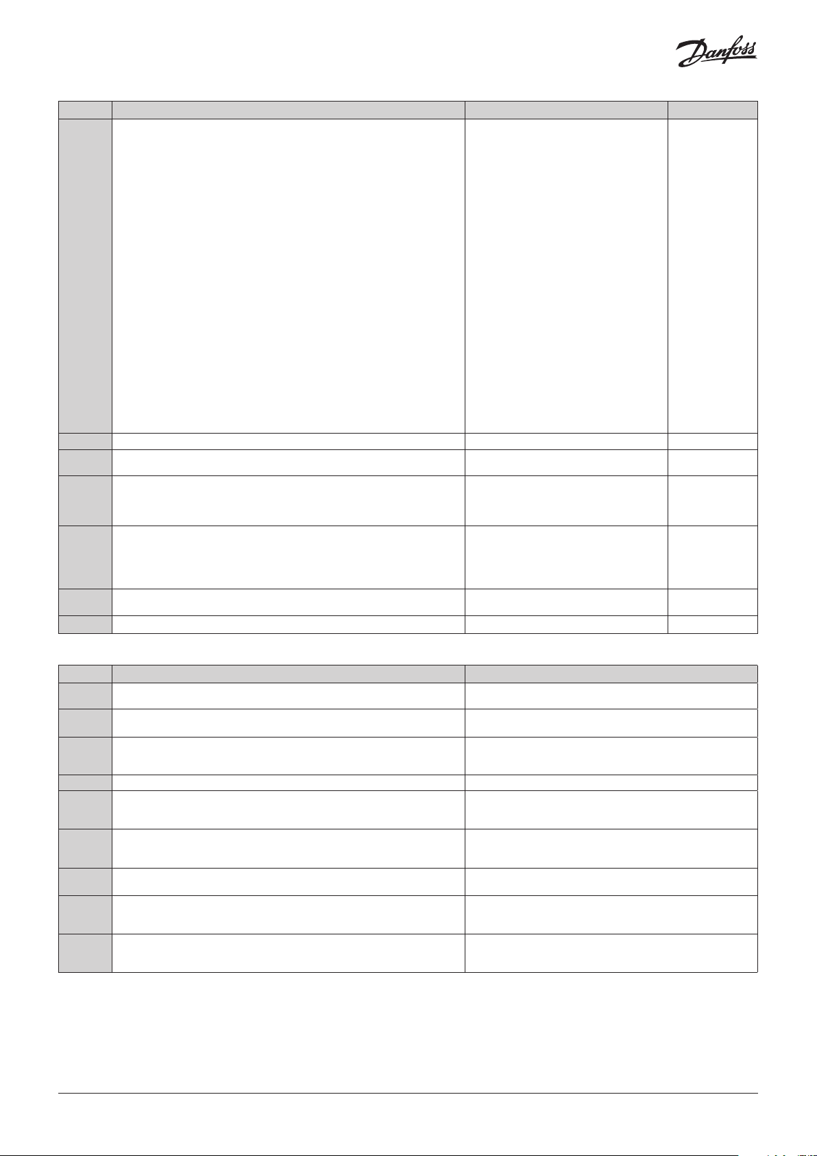
Common dig. inputs
switchboard
switchboard
Common probes
Digital input 1
Digital input 2
Ambient probe
Defrost probe
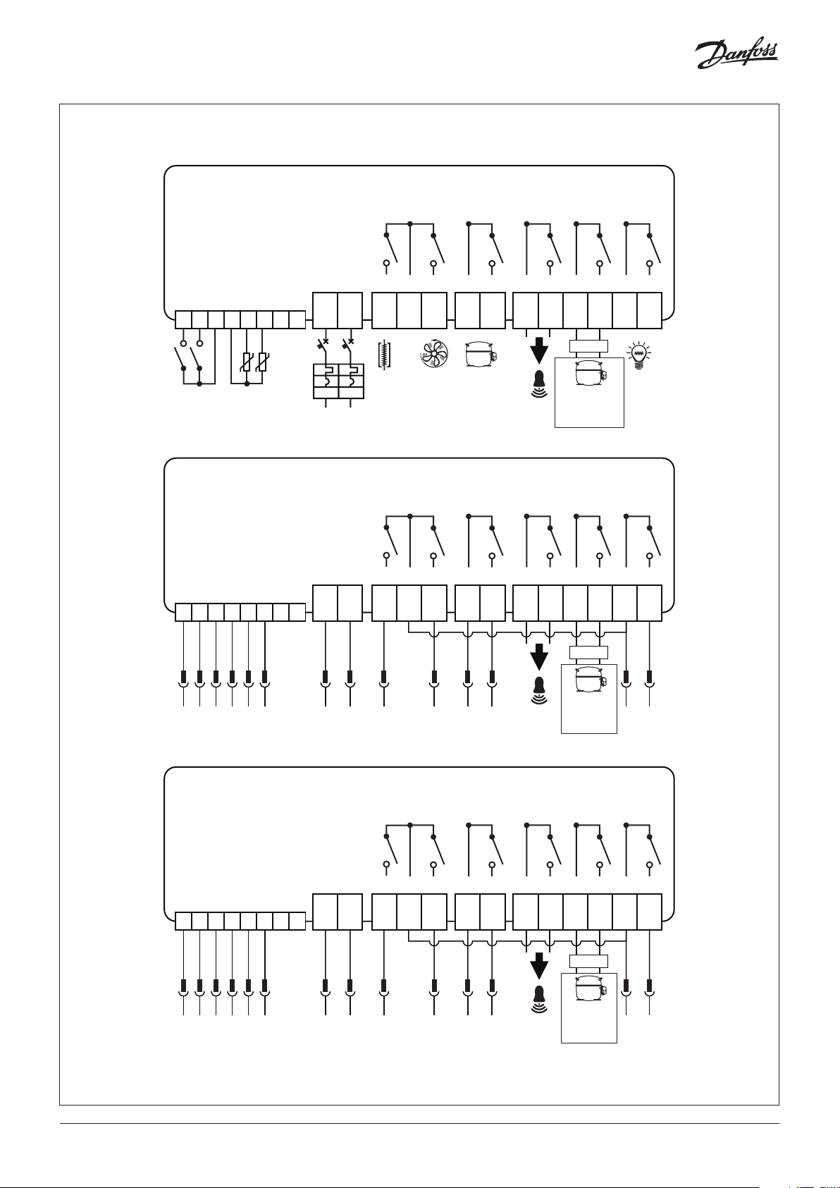
OPTYMA™ Control, single phase
MODBUS A+
MODBUS B-
Power
Supply
230 V AC
Defrost
Fans Compr.Aux1/All.Aux2
Light
1 2 3 4 5 6 7 8
Common dig. inputs
Comp. protection
Door switch
Common probes
OPTYMA™ Control, three phase (4 HP)
Ambient probe
Defrost probe
MODBUS A+
1 2 3 4 5 6 7 8
12313 14 15
JB01.1
JB01.2
JB01.3
JB01.13
JB01.14
JB01.15
9 10 11 12 13 14 15 16 17 20 21 18 19
Common
enable
/d /d
F
N
Condensing
unit
Electric
switchboard
MODBUS B-
Power
Supply
230 V AC
Defrost
Fans Compr.Aux1/All.Aux2
9 10 11 12 13 14 15 16 17 20 21 18 19
9
JB01.55JB01.66JB01.77JB01.8L8JB01.44JB01.9
enable
Condensing
unit
Electric
Light
L10
JB01.10
L11
JB01.11
Common dig. inputs
Comp. protection
Door switch
1 2 3 4 5 6 7 8
12313 14 15
JB01.1
JB01.2
2 | AN30923034432301-000102
OPTYMA™ Control, three phase (7.5 HP)
Common probes
Ambient probe
Defrost probe
MODBUS A+
JB01.3
JB01.13
JB01.14
JB01.15
MODBUS B-
Power
Supply
230 V AC
Defrost
Fans Compr.Aux1/All.Aux2
9 10 11 12 13 14 15 16 17 20 21 18 19
9
JB01.55JB01.66JB01.77JB01.88JB01.44JB01.9
enable
Condensing
unit
Electric
Light
L10
L11
JB01.10
JB01.11
© Danfoss | DCS (vt) | 2020.05
Page 3
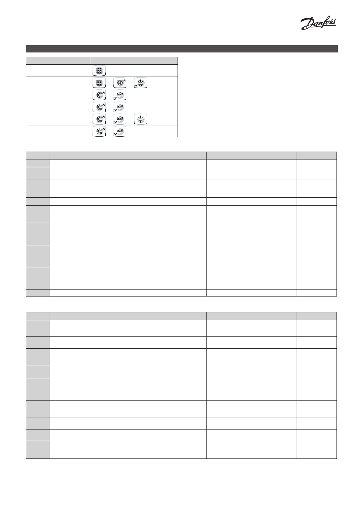
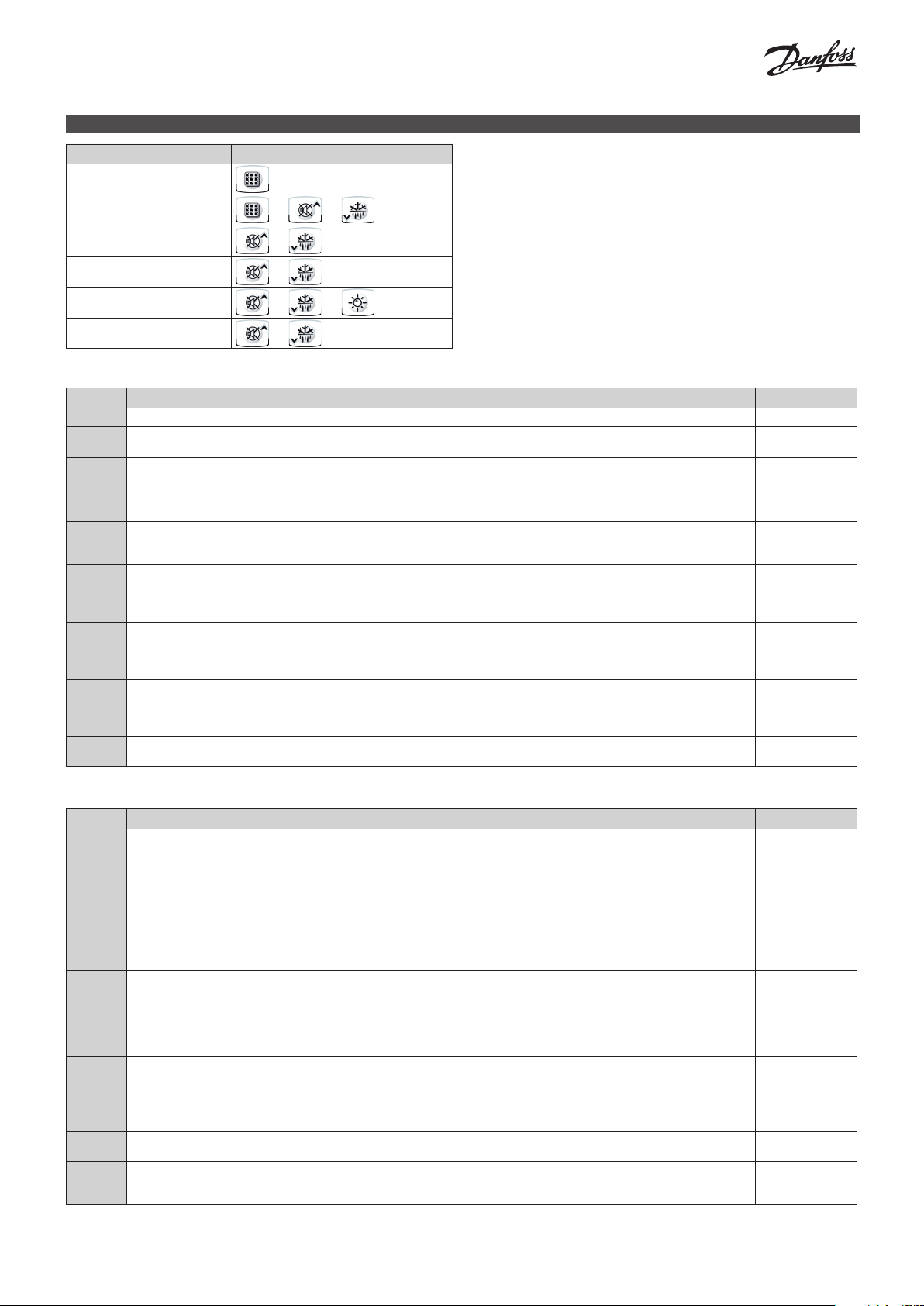
Function Press
View set point
ENGLISH
Change set point
Change menu “User level”
Return
Change menu “Installer level”
Return
+
+
+
+
+
/
(3 seconds)
(3 seconds)
+
(3 seconds)
(3 seconds)
List of level 1 variables (user level)
Variables Meaning Value Default
r0 Temperature difference compared to main SETPOINT 0.2 – 10 °C 2 °C
d0 Defrost interval (hours)
If d0 = 0 cyclical defrosts Off
d2 End-of-defrost setpoint.
Defrost is not executed if the temperature read by the defrost sensor is greater than
d2. (If the sensor is faulty defrosting is timed)
d3 Max defrost duration (minutes) 1 – 240 min 25 min
d7 Drip duration (minutes)
At the end of defrost the compressor and fans remain at standstill for time d7, the
defrost LED on the front panel flashes.
F5 Fan pause after defrost (minutes)
Allows fans to be kept at standstill for a time F5 after dripping. This time begins at the
end of dripping. If no dripping has been set the fan pause starts directly at the end of
defrost.
A1 Minimum temperature alarm
Allows user to define a minimum temperature for the room being refrigerated. Below
value A1 an alarm trips: the alarm LED flashes, displayed temperature flashes and the
buzzer sounds to indicate the problem.
A2 Maximum temperature alarm
Allows user to define a maximum temperature for the room being refrigerated. Above
value A2 an alarm trips: the alarm LED flashes, displayed temperature flashes and the
buzzer sounds to indicate the problem.
tEu Evaporator sensor temperature display (displays nothing if dE =1) Evaporator temperature read only
0 – 24 hours 4 hours
-35 – 45 °C 15 °C
0 – 10 min 0 min
0 – 10 min 0 min
-45 – (A2-1) °C -45 °C
(A1+1) – 99 °C 99 °C
List of level 2 variables (installer level)
Variables Meaning Value Default
F3 Fan status with compressor off 0 = Fans run continuously
F4 Fan pause during defrost 0 = Fans run during defrost
F6 Evaporator fans activation for air recirculation.
The fans activate for a time defined by F7 if they have not started working for the F6
time. If activation time coincides with the defrosting time, end of defrosting is awaited.
F7 Evaporator fans duration for air recirculation.
Fans working time for F6
dE Sensor presence
If the evaporator sensor is disabled defrosts are carried out cyclically with period d0:
defrosting ends when an external device trips and closes the remote defrost contact or
when time d3 expires.
d1 Defrost type, cycle inversion (hot gas) or with heater elements 0 = heating element
dPo Defrost at Power On 0 = disabled
dSE Smart defrost 0 = disabled
dSt Smart defrost Setpoint (if dSE=1)
The counting of the time between the defrost is incremented only if the compressor is
ON and the evaporator temperature is less than dSt.
1 = Fans only run when compressor is working
2 = Fans disabled
1 = Fans do not run during defrost
0 – 240 min
0 = (function not activated)
0 – 240 sec 10 sec
0 = evaporator sensor present
1 = no evaporator sensor
1 = hot gas
2 = heater with temperature control
1 = defrost at power-on (if possible)
1 = enabled
-30 – 30 °C 1 °C
0 min
1
1
0
0
0
0
© Danfoss | DCS (vt) | 2020.05
AN30923034432301-000102 | 3
Page 4
Variables Meaning Value Default
dFd Display viewing during Defrost 0 = current temperature
Ad Modbus Network address 0 – 247 0
Bdr Modbus baudrate 0 = 300 baud
Prt Modbus parity check 0 = none
Ald Minimum and maximum temperature signalling and alarm display delay 0 – 240 min 120 min
C1 Minimum time between shutdown and subsequent switching on of the compressor 0 – 15 min 0 min
CAL Cold room sensor value correction -10 – 10 °C 0 °C
CE1 Duration of compressor ON time in the case of faulty ambient probe
(emergency mode).
If CE1=0 the emergency mode in the presence of error E0 remains disabled, the
compressor remains off and defrosting is prevented in order to conserve the
remaining cold.
CE2 Duration of compressor OFF time in the case of faulty ambient probe
(emergency mode).
doC Compressor safety time for door switch: when the door is opened the evaporator
fans shut down and the compressor will continue working for time doC, after which it
will shut down.
tdo Compressor restart time after door opening. When the door is opened and after tdo
time, it’s setted back the normal functioning giving door open alarm (Ed)
If the door switch is closed and the light stays on for a longer time than tdo light cell
alarm is signaled (E9).
With tdo=0 the parameter is disabled.
Fst FAN shutdown TEMPERATURE
The fans will stop if the temperature value read by the evaporator sensor is higher
than this value.
Fd Fst differential 1 – 10 °C 2 °C
LSE Minimum value attributable to setpoint. -45 – (HSE-1) °C -45 °C
HSE Maximum value attributable to setpoint. (LSE+1) – 99°C 99 °C
AU1 Auxiliary/alarm relay 1 control -6 (NC) = relay de-energised during stand-by.
AU2 Auxiliary/alarm relay 2 control (like AU1 ) 5
StA Temperature setting for auxiliary relay -45 – 99 °C 0 °C
nSC Correction factor for the SET button during night operation (energy saving)
(with In1 or In2 = 8 or -8)
During night operation the control set is: Set Control = Set + nSC
In night mode decimal point flashes.
1 = temperature at the start of the defrost
2 = “DEF”
1 = 600 baud
2 = 1200 baud
3 = 2400 baud
4 = 4800 baud
5 = 9600 baud
6 = 14400 baud
7 = 19200 baud
8 = 38400 baud
1 = even
2 = odd
0 – 240 min
0 = disabled
5 – 240 min 5 min
0 – 5 min 0 min
0 – 240 min
0 = disabled
-45 – 99 °C 99 °C
-5 (NC) = Contact for casing element control
(AUX relay closed with compressor
output inactive).
-4 (NC) = pump down function(NC, see CHAP
5.16).
-3 (NC) = automatic auxiliary relay managed by
StA temp. setting with 2°C differential
(NC).
-2 (NC) = manual auxiliary relay controlled via
AUX key (NC).
-1 (NC) = alarm relay (NC).
0 = relay deactivated.
1 (NO) = alarm relay (NO).
2 (NO) =manual auxiliary relay controlled via
AUX key (NO).
3 (NO) = automatic auxiliary relay managed by
StA temp. setting with 2°C differential
(NO).
4 (NO) = pump down function (NO, see CHAP
5.16).
5 (NO) = free voltage contact for condensing
unit (AUX relay and compressor relay
in parallel).
6 (NO) = relay excited during stand-by.
-20 – 20 °C 0 °C
1
8
1
0 min
0 min
-1
4 | AN30923034432301-000102
© Danfoss | DCS (vt) | 2020.05
Page 5
Variables Meaning Value Default
In1 INP-1 input setting 8 = Night mode digital input (energy saving,
In2 INP-2 input setting ( like In1 ) 1
bEE Buzzer enable 0 = disabled
mOd Thermostat functioning mode 0 = Cold function
P1 Password type of protection
(active when PA is not equal 0)
PA Password
(see P1 for the type of protection)
reL Release software indicates software version read only
N.O.)
7 = Stop defrosting remotely (N.O.) (reads rising
edge of impulse)
6 = Start defrosting remotely (N.O.) (reads rising
edge of impulse)
5 = Stand-by remotely (N.O.) (In order to indicate
Stand-By mode, the display shows ‘In5’
alternating with the current view)
4 = Pump-down pressure switch (N.O.)
3 = Man-in-room alarm (N.O.)
2 = Compressor protection (N.O.)
1 = Door switch (N.O.)
0 = disabled
-1 = Door switch (N.C.)
-2 = Compressor protection (N.C.)
-3 = Man-in-room alarm (N.C.)
-4 = Pump-down pressure switch (N.C.)
-5 = Stand-by remotely (N.C.) (In order to
indicate Stand-By mode, the display shows
‘In5’ alternating with the current view)
-6 = Start defrosting remotely (N.C.) (reads falling
edge of impulse)
-7 = Stop defrosting remotely (N.C.) (reads falling
edge of impulse)
-8 = Night mode digital input (energy saving,
N.C.)
1 = enabled
1 = Hot function
(in this mode defrosting and fan disable Fst
are excluded)
0 = only display set point
1 = display set point, AUX, light access
2 = access in programming not permitted
3 = access in second level programming not
permitted
0...999
0 = not active
2
1
0
3
0
Troubleshooting
Alarm code Possible cause Solution
E0 Cold room temperature sensor not working properly • Check that cold room temperature sensor is working properly
E1 Defrost sensor not working properly (in this case defrosts will last time d3) • Check that defrost sensor is working properly
E2 Eeprom alarm
An EEPROM memory alarm has been detected
(All outputs except the alarm one are deactivated)
E8 Man in cold room alarm • Reset the alarm input inside the cold room
Ec Compressor protection tripped
(e.g. thermal protection or max pressure switch)
(All outputs except the alarm one – where applicable – are deactivated)
Ed Open door Alarm. When the door is opened and after tdo time, it’s setted back the
normal functioning giving door open alarm (Ed)
E9 Cell light alarm.
The light of the cell has been on for a time greater than tdo.
EH Maximum temperature alarm.
The temperature inside the cold room has exceeded the max. temperature alarm
setting (see variables A2, user programming level)
EL Minimum temperature alarm.
The temperature inside the cold room has exceeded the min. temperature alarm
setting (see variables A1, user programming level)
• If the problem persists replace the sensor
• If the problems persists replace the sensor
• Switch unit off and back on
• Check that compressor is working properly
• Check compressor absorption
• If the problem persists contact the technical assistance service
• Check door switch status
• Check door switch connections
• If the problem persists contact the technical assistance service
• Turn off the light
• Check that the compressor is working properly.
• Sensor not reading temperature properly or compressor start/stop
control not working.
• Check that the compressor is working properly.
• Sensor not reading temperature properly or compressor start/stop
control not working.
© Danfoss | DCS (vt) | 2020.05
AN30923034432301-000102 | 5
Page 6
Functie Pers
Voor setpoint
NEDERLANDS
Modificeren setpoint
Modificeren menu “Gebruikers
niveau”
Menu verlaten
Modificeren menu
“Installateursniveau”
Menu verlaten
+
+
+
+
+
/
(3 seconden)
(3 seconden)
+
(3 seconden)
(3 seconden)
Lijst met niveau 1 variabelen (gebruikersniveau)
Variabelen Verklaring Waarde Fabr. Inst.
r0 Temperatuur differentie vergeleken met het SETPOINT 0.2 – 10 °C 2 °C
d0 Ontdooi interval (Uur)
indien d0 = 0 cyclische ontdooiing Uit
d2 Ontdooiing setpoint
Ontdooiing wordt niet uitgevoerd als de waarde van de temperatuur hoger is dan "d2".
(Als de sensor defect is wordt de ontdooiing op tijd uitgevoerd)
d3 Maximale ontdooitijd (minuten) 1 – 240 min 25 min
d7 Duur druptijd (minuten)
Na een ontdooibeëindiging blijven de compressor en ventilator gedurende tijd d7
stilstaan, De ontdooi LED op het frontpaneel knippert.
F5 Ventilatorpauze na ontdooiing (minuten)
De ventilator blijft na de druptijd stilstaan gedurende tijd F5. Deze tijd begint na het
einde van de druptijd. Als er geen druptijd is ingesteld start de ventilatorpauze direct
na het einde van de ontdooiing.
A1 Minimum temperatuuralarm
Maakt het mogelijk voor de gebruiker om een minimum ruimtetemperatuur in te
stellen. Beneden waarde A1 schakelt het alarmcontact: het alarm LED knippert,
weergave temperatuur knippert en de zoemer gaat aan om het probleem te melden.
A2 Maximum temperatuuralarm
Maakt het mogelijk voor de gebruiker om een maximum ruimtetemperatuur in te
stellen. Boven waarde A2 schakelt het alarmcontact: het alarm LED knippert, weergave
temperatuur knippert en de zoemer gaat aan om het probleem te melden.
tEu Verdampersensor temperatuurweergave Geeft verdampertemperatuur weer
0 – 24 uur 4 uur
-35 – 45 °C 15°C
0 – 10 min 0 min
0 – 10 min 0 min
-45 – (A2-1) °C -45 °C
(A1+1) – 99 °C 45 °C
Alleen lezen
(geeft niets weer als dE =1)
Lijst met niveau 2 variabelen (installateursniveau)
Variabelen Verklaring Waarde Fabr. Inst.
F3 Ventilatorstatus bij compressor uit 0 = ventilatoren draaien continue
F4 Ventilator pauze tijdens ontdooiing 0 = ventilatoren draaien tijdens ontd.
F6 Verdamperventilatoren activeren voor luchtrecirculatie.
De ventilatoren worden gedurende een door F7 gedefinieerde tijd geactiveerd als ze
niet voor de F6-tijd zijn begonnen te werken. Als de activeringstijd samenvalt met de
ontdooitijd, wacht u het einde van het ontdooien.
F7 Verdamper ventilatieduur voor luchtrecirculatie.
Fans werktijd voor F6
dE Sensor aanwezigheid
Als de verdampersensor Is aangesloten worden ontdooiingen uitgevoerd volgens
cyclusperiode d0: ontdooiing eindigt als een externe sensor aanspreekt en het remote
ontdooicontact schakelt en sluit of als tijd d3 afloopt.
d1 Type ontdooicyclus, omkeersysteem (heet gas) of met ontdooi-elementen 0 = verwarmingselement
dPo Ontdooien bij inschakelen 0 = uitgeschakeld
dSE Slim ontdooien 0 = uitgeschakeld
dSt Smart Defrost Setpoint (indien dSE = 1)
Het tellen van de tijd tussen het ontdooien wordt alleen geïncrementeerd als de
compressor AAN staat en de verdampertemperatuur lager is dan dSt.
1 = ventilatoren alleen in bedrijf als compressor
in bedrijf is
2 = Fans uitgeschakeld
1 = ventilatoren staan stil tijdens ontd.
0 – 240 min
0 = (functie niet geactiveerd)
0 – 240 sec 10 sec
0 = verdampersensor aanwezig
1 = geen verdampersensor
1 = heet gas
2 = kachel met temperatuurregeling
1 = ontdooien bij inschakelen (indien mogelijk)
1 = ingeschakeld
-30 – 30 °C 1 °C
1
1
0 min
0
0
0
0
6 | AN30923034432301-000102
© Danfoss | DCS (vt) | 2020.05
Page 7
Variabelen Verklaring Waarde Fabr. Inst.
dFd Weergave weergeven tijdens ontdooien 0 = huidige temperatuur
Ad Modbus Netwrok-adres 1 – 247 (con SEr=1) 0
Bdr Modbus baudrate 0 = 300 baud
Prt Modbus pariteitscontrole 0 = none
Ald Minimum- en maximum temperatuur signalering en alarm weergave vertraging 0 – 240 min 120 min
C1 Minimum tijd tussen uit- en inschakelen van de compressor. 0 – 15 min 0 min
CAL Ruimtesensor waarde correctie -10 – 10 °C 0 °C
CE1 Duur van de inschakeltijd van de compressor in het geval van een defecte
omgevingssonde (noodmodus).
Als CE1 = 0 blijft de noodmodus in aanwezigheid van fout E0 uitgeschakeld, de
compressor blijft uitgeschakeld en ontdooien wordt voorkomen om de resterende
koude te behouden.
CE2 Duur van de UIT-tijd van de compressor in het geval van een defecte
omgevingssonde (noodmodus).
doC Compressor veiligheidstijd voor deurschakelaar: als de deur open is schakelt de
verdamperventilator en de compressor zal continue werken gedurende tijd doC,
daarna schakelt hij uit.
tdo Compressor herstarttijd na opening van de deur.
Wanneer de deur wordt geopend en na de tdo-tijd, is het teruggekeerd naar de
normaal functionerende deur open alarm (ED). Als de deurschakelaar is gesloten en
het lampje langer blijft branden dan wordt het Tdo-lichtcelalarm gesignaleerd (E9).
Met tdo = 0 is de parameter uitgeschakeld.
Fst Ventilator uitschakeltemperatuur
De ventilator stopt als de temperatuur waarde van de verdampersensor hoger is dan
deze waarde.
Fd Differentie voor parameter "Fst" 1 – 10 °C 2°C
LSE Minimum waarde in te stellen setpoint. -45 – (HSE-1) °C -45 °C
HSE Maximum waarde in te stellen setpoint. (LSE+1) – 99 °C 99 °C
AU1 Besturing relais hulp/alarm 1 6 (NC) = relais gedeactiveerd tijdens stand-by
AU2 Besturing relais hulp/alarm 2 (zoals AU1) 5
StA Temp. instelling voor aux. relais -45 – 99 °C 0 °C
nSc Correctiefactor voor de SET-knop tijdens nachtbedrijf
(energiebesparend) (met In1 of In2 = 8 of -8)
Tijdens nachtbedrijf is de controleset:
Set Control = Set + nSC
In de nachtmodus knippert de komma.
1 = temperatuur aan het begin van het
ontdooien
2 = "DEF"
1 = 600 baud
2 = 1200 baud
3 = 2400 baud
4 = 4800 baud
5 = 9600 baud
6 = 14400 baud
7 = 19200 baud
8 = 38400 baud
1 = even
2 = odd
0 – 240 min
0 = uitgeschakeld
5 – 240 min 5 min
0 – 5 minuten 0 min
0 – 240 min
0 = uitgeschakeld
-45 – 99 °C 99 °C
-5 (NC) = Contact voor
behuizingelementcontrole (AUX-relais
gesloten met compressoruitgang
inactief).
-4 (NC) = pump-down-functie (NC, zie CHAP
5.16)
-3 (NC) = automatisch hulprelais beheerd door
StA temp. instelling met differentieel
van 2 ° C (NC)
-2 (NC) = handmatig hulprelais geregeld via
AUX-toets (NC)
-1 (NC) = alarmrelais (NC)
0 = relais gedeactiveerd
1 (NO) = alarmrelais (NO)
2 (NO) = handmatig hulprelais geregeld via AUX-
sleutel (NO)
3 (NO) = automatisch hulprelais beheerd door
StA temp. instelling met differentieel
van 2 °C (NO)
4 (NO) = pump-down-functie (NEE, zie CHAP
5.16)
5 (NO) = vrij spanningscontact voor
condensoreenheid (parallel AUX-relais
en compressorrelais)
6 (NO) = relais geactiveerd tijdens stand-by
-20 – 20 °C 0 °C
1
8
1
0 min
0 min
-1
© Danfoss | DCS (vt) | 2020.05
AN30923034432301-000102 | 7
Page 8

Variabelen Verklaring Waarde Fabr. Inst.
In1 INP-1-ingangsinstelling 8 = digitale ingang nachtmodus
In2 INP-2-ingangsinstelling (zoals In1) 1
bEE Zoemer inschakelen 0 = uitgeschakeld
mOd Thermostaat werkende modus 0 = Koude functie
P1 Wachtwoord beveiliging
(actief als PA niet gelijk is 0)
P2 Wachtwoord
(zie P1 voor het type beveiliging)
reL Software versie weergave software versie (Alleen uitleesbaar)
(energiebesparing, N.O.)
7 = Stop met ontdooien op afstand (N.O.) (geeft
de stijgende flank van de impuls aan)
6 = Ontdooien op afstand starten (N.O.) (geeft de
stijgende flank van de impuls aan)
5 = Stand-by op afstand (N.O.) (Om de Stand-By-
modus aan te geven, toont het scherm 'In5'
afgewisseld met de huidige weergave)
4 = Pump-down drukschakelaar (N.O.)
3 = Man-in-room alarm (N.O.)
2 = Compressorbeveiliging (N.O.)
1 = Deurschakelaar (N.O.)
0 = uitgeschakeld
-1 = Deurschakelaar (N.C.)
-2 = Compressorbeveiliging (N.C.)
-3 = Alarm man-in-kamer (N.C.)
-4 = Pump-down drukschakelaar (N.C.)
-5 = Stand-by op afstand (N.C.) (Om de Stand-By-
modus aan te geven, toont het display 'In5',
afgewisseld met de huidige weergave)
-6 = Start ontdooien op afstand (N.C.) (leest
dalende flank van de impuls)
-7 = Stop met ontdooien op afstand (N.C.) (leest
de dalende flank van de impuls)
-8 = digitale ingang nachtmodus
(energiebesparing, N.C.)
1 = ingeschakeld
1 = Hot-functie
(in deze modus zijn ontdooien en ventilator
uitschakelen Fst uitgesloten)
0 = alleen weergave van setpoint
1 = weergave setpoint, AUX, verlichting toegang
2 = toegang tot programmering niet toegestaan
3 = toegang tot tweede programmeerniveau is
niet toegestaan
0...999
0 = niet actief
2
0
0
3
0
Probleemoplossing
Alarm code Mogelijke oorzaak Oplossing
E0 Koelcel temperatuursensor werkt niet optimaal. • Controleer of de koelcel temperatuursensor goed werkt.
E1 Ontdooisensor werkt niet goed (In dit geval duurt de ontdooiing tijd d3 ) • Controleer of de ontdooisensor goed werkt.
E2 Eeprom alarm
Een EEPROM geheugen alarm was gedetecteerd.
(alle uitgangen, muv het alarm worden uitgeschakeld)
E8 Man in koelcel alarm • Reset het alarm binnen in de koelcel
Ec Compressor beveiliging aangesproken (thermische beveiliging of max druk
pressostaat)
(alle uitgangen, muv het alarm worden uitgeschakeld)
Ed Open deur Alarm. Wanneer de deur is geopend wordt na de tdo tijd de regelaar terug
op normaal gezet en schakelt hij het deur alarm uit
E9 Cellicht alarm.
Het licht van de cel brandt langer dan tdo.
EH Maximum temperatuur alarm.
De temperatuur in de koude ruimte heeft de max. temperatuuralarminstelling (zie
variabelen A2, gebruikersprogrammeerniveau)
EL Minimum temperatuur alarm.
De temperatuur in de koude ruimte heeft de min. temperatuuralarminstelling (zie
variabelen A1, gebruikersprogrammeerniveau)
• Blijft het probleem bestaan, vervang dan de sensor.
• Blijft het probleem zich voordoen, vervang dan de sensor.
• Zet het toestel uit en opnieuw aan
• Controleer of de compressor goed werkt.
• Controleer het compressorvermogen.
• Blijft het probleem zich voordoen, neem dan contact op met de
leverancier.
• Controleer de deurschakelaar
• Controleer de aansluitingen
• Blijft het probleem zich voordoen, neem dan contact op met de
leverancier.
• Doe het licht uit
• Controleer of de compressor correct werkt.
• Sensor leest de temperatuur niet goed of de compressor start / stop-
controle werkt niet.
• Controleer of de compressor correct werkt.
• Sensor leest de temperatuur niet goed of de compressor start / stop-
controle werkt niet.
8 | AN30923034432301-000102
© Danfoss | DCS (vt) | 2020.05
Page 9

Funktion Tasten
Sollwert Anzeige
DEUTSCH
Sollwert ändern
Änderung in Benutzerebene
Zurück
Änderung in
Inbetriebnahmeebene
Zurück
+
+
+
+
+
/
(3 sekunden)
(3 sekunden)
+
(3 sekunden)
(3 sekunden)
Parameterliste 1
Parameter Beschreibung Wert
r0 Temperaturdifferenz im Vergleich zum Hauptsollwert 0.2 – 10 °C 2 °C
d0 Auftauintervall (Stunden)
Wenn d0 = 0 zyklisch Abtau Aus
d2 Sollwert für Abtauende.
Die Abtauung wird nicht ausgeführt, wenn die vom Abtaufühler gemessene
Temperatur größer als d2 ist.
(Wenn der Sensor fehlerhaft ist, wird das Abtauen zeitgesteuert).
d3 Maximale Auftauzeit (Minuten) 1 – 240 min 25 min
d7 Tropfdauer (Minuten)
Am Ende der Abtauung bleiben Kompressor und Ventilatoren zum Zeitpunkt d7 im
Stillstand.
Die Abtau-LED an der Vorderseite blinkt.
F5 Lüfterpause nach dem Abtauen (Minuten)
Ermöglicht, dass die Lüfter nach dem Abtropfen eine Zeit lang F5 stehen bleiben.
Diese Zeit beginnt am Ende des Abtropfens. Wenn kein Abtropfen eingestellt ist,
beginnt die Lüfterpause direkt nach dem Abtauen.
A1 Mindesttemperaturalarm
Ermöglicht dem Benutzer die Festlegung einer Mindesttemperatur für den zu
kühlenden Raum. Unter dem Wert A1 wird ein Alarm ausgelöst: Die Alarm-LED
blinkt, die angezeigte Temperatur blinkt und der Summer ertönt, um das Problem
anzuzeigen.
A2 Alarm für maximale Temperatur
Ermöglicht dem Benutzer, eine Höchsttemperatur für den zu Kühlraum festzulegen.
Oberhalb von Wert A2 wird ein Alarm ausgelöst: Die Alarm-LED blinkt, die angezeigte
Temperatur blinkt und der Summer ertönt, um das Problem anzuzeigen.
tEu Temperaturanzeige des Verdampferfühlers
(zeigt nichts an, wenn dE = 1 ist)
0 – 24 std 4 std
-35 – 45 °C 15 °C
0 – 10 min 0 min
0 – 10 min 0 min
-45 – (A2-1) °C -45 °C
(A1+1) – 99 °C 99 °C
Verdampfungstemperatur Schreibgeschützt
Voreingestellter wert
Parameterliste 2
Parameter Beschreibung Wert
F3 Lüfterstatus bei ausgeschaltetem Kompressor 0 = Lüfter laufen ununterbrochen
F4 Lüfterpause während der Abtauung 0 = Lüfter laufen während der Abtauung
F6 Aktivierung der Verdampferlüfter zur Luftumwälzung.
Die Lüfter werden für eine durch F7 festgelegte Zeit aktiviert, wenn sie nicht für die
F6-Zeit begonnen haben. Wenn die Aktivierungszeit mit der Abtauzeit übereinstimmt,
wird das Ende der Abtauung abgewartet.
F7 Verdampferlüfterdauer für die Luftumwälzung.
Arbeitszeit der Fans für F6
dE Präsenz des Sensors
Wenn der Verdampferfühler deaktiviert ist, werden Abtauungen zyklisch mit der
Zeitdauer d0 ausgeführt: Die Abtauung endet, wenn ein externes Gerät auslöst und
den Fernabtaukontakt schließt oder wenn die Zeit d3 abläuft.
d1 Abtautyp, Zyklusinversion (Heißgas) oder mit Heizelementen 0 = Heizelement
dPo Abtauen beim Einschalten 0 = deaktiviert
dSE Intelligente Abtauung 0 = deaktiviert
dSt Intelligenter Abtau-Sollwert (wenn dSE = 1)
Das Zählen der Zeit zwischen dem Abtauen wird nur erhöht, wenn der Verdichter
eingeschaltet ist und die Verdampfertemperatur unter dSt liegt.
© Danfoss | DCS (vt) | 2020.05
1 = Lüfter laufen nur, wenn der Kompressor läuft
2 = Lüfter deaktiviert
1 = Lüfter laufen nicht während der Abtauung
0 – 240 min
0 = (Funktion nicht aktiviert)
0 – 240 sec 10 sec
0 = Verdampferfühler vorhanden
1 = kein Verdampferfühler
1 = heißes Gas
2 = Heizung mit Temperaturregelung
1 = Abtauen beim Einschalten (wenn möglich)
1 = aktiviert
-30 – 30 °C 1 °C
AN30923034432301-000102 | 9
Voreingestellter wert
1
1
0 min
0
0
0
0
Page 10

Parameter Beschreibung Wert
dFd Displayanzeige während des Abtauens 0 = aktuelle Temperatur
Ad Modbus Netzadresse 1 – 247 (con SEr=1) 0
Bdr Modbus-Baudrate 0 = 300 baud
Prt Modbus-Paritätsprüfung 0 = none
Ald Minimale und maximale Temperatursignalisierung und Verzögerung der
Alarmanzeige
C1 Minimale Zeit zwischen dem Abschalten und dem anschließenden Einschalten des
Kompressors.
CAL Kaltraumsensorwertkorrektur -10 – 10 °C 0 °C
CE1 Einschaltdauer des Verdichters bei fehlerhafter Umgebungssonde (Notfallmodus).
Wenn CE1 = 0 ist, bleibt der Notfallmodus bei Fehler E0 deaktiviert, der Kompressor
bleibt ausgeschaltet und ein Abtauen wird verhindert, um die verbleibende Kälte zu
erhalten.
CE2 Dauer der Ausschaltzeit des Verdichters bei fehlerhafter Umgebungssonde
(Notfallmodus).
doC Kompressorsicherheitszeit für Türschalter: Wenn die Tür geöffnet wird, werden die
Verdampferlüfter abgeschaltet und der Kompressor arbeitet für die Zeit doC weiter,
danach wird er heruntergefahren.
tdo Wiederanlaufzeit des Kompressors nach dem Öffnen der Tür. Wenn die Tür geöffnet
ist und nach Ablauf dieser Zeit ist die normale Funktion wiederhergestellt, die einen
Türalarm auslöst (Ed). Wenn der Türschalter geschlossen ist und das Licht länger
eingeschaltet bleibt, wird der Alarm "Lichtzelle" (E9) gemeldet. Bei tdo = 0 ist der
Parameter deaktiviert.
Fst Fan herunterfahren der temperatur
Die Lüfter halten an, wenn der vom Verdampferfühler gemessene Temperaturwert
diesen Wert überschreitet.
Fd Fst Differenzial 1 – 10 °C 2 °C
LSE Minimalwert, der dem Sollwert zugeordnet werden kann -45 – (HSE-1) °C -45 °C
HSE Maximalwert, der dem Sollwert zugeordnet werden kann (LSE+1) – 99 °C 99 °C
AU1 Hilfs / Alarmrelais 1 Steuerung -6 (NC) = Relais fällt während des Standby
AU2 Hilfs / Alarmrelais 2 Steuerung (like AU1 ) 5
StA Temperatureinstellung für Hilfsrelais -45 – 99 °C 0 °C
nSC Korrekturfaktor für die SET-Taste im Nachtbetrieb (Energieeinsparung) (mit In1 oder
In2 = 8 oder -8)
Während des Nachtbetriebs ist der Steuerungssatz:
Set Control = Set + nSC
Im Nachtmodus blinkt der Dezimalpunkt.
1 = Temperatur zu Beginn der Abtauung
2 = "DEF"
1 = 600 baud
2 = 1200 baud
3 = 2400 baud
4 = 4800 baud
5 = 9600 baud
6 = 14400 baud
7 = 19200 baud
8 = 38400 baud
1 = even
2 = odd
0 – 240 min 120 min
0 – 15 min 0 min
0 – 240 min
0 = deaktiviert
5 – 240 min 5 min
0 bis 5 min 0 min
0 – 240 min
0 = deaktiviert
-45 – 99 °C 99 °C
-5 (NC) = Kontakt für Gehäuseelementsteuerung
(AUX-Relais geschlossen,
Kompressorausgang inaktiv).
-4 (NC) = Abpumpfunktion (NC, siehe CHAP 5.16)
-3 (NC) = automatisches Hilfsrelais, das von StATemp. Gesteuert wird. Einstellung mit 2
° C Differenzial (NC)
-2 (NC) = manuelles Hilfsrelais, gesteuert über
AUX-Taste (NC)
-1 (NC) = Alarmrelais (NC)
0 = Relais deaktiviert
1 (NO) = Alarmrelais (NO)
2 (NO) = manuelles Hilfsrelais, gesteuert über die
AUX-Taste (NO)
3 (NO) = automatisches Hilfsrelais, das von StA-
Temp. Gesteuert wird. Einstellung mit 2
° C Differenzial (NO)
4 (NO) = Abpumpfunktion (NO, siehe KAPITEL
5.16)
5 (NO) = freier Spannungskontakt für die
Verflüssigungsanlage (Parallelrelais AUX
und Verdichter)
6 (NO) = Relais erregt im Bereitschaftsmodus
-20 – 20 °C 0 °C
Voreingestellter wert
1
8
1
0 min
0 min
-1
10 | AN30923034432301-000102
© Danfoss | DCS (vt) | 2020.05
Page 11

Parameter Beschreibung Wert
In1 INP-1 Eingangseinstellung 8 = Digitaleingang im Nachtmodus
In2 INP-2 Eingangseinstellung (wie In1) 1
bEE Summer aktivieren 0 = deaktiviert
mOd Thermostat-Betriebsmodus 0 = Kaltfunktion
P1 Kennwortschutzart
(aktiv, wenn PA nicht gleich 0 ist)
PA Passwort
(siehe P1 für die Schutzart)
reL Software freigeben Zeigt die Softwareversion an (schreibgeschützt)
(Energiesparen, N.O.)
7 = Abtauung aus der Ferne stoppen (N. O.) (liest
die steigende Flanke des Impulses)
6 = Abtauung aus der Ferne starten (N.O.) (liest
die steigende Flanke des Impulses)
5 = Remote-Standby (N.O.) (Um den Standby-
Modus anzuzeigen, zeigt das Display
abwechselnd "In5" mit der aktuellen Ansicht
an.)
4 = Abpumpdruckschalter (N.O.)
3 = Man-in-Room-Alarm (N.O.)
2 = Kompressorschutz (N.O.)
1 = Türschalter (N.O.)
0 = deaktiviert
-1 = Türschalter (N.C.)
-2 = Kompressorschutz (N.C.)
-3 = Man-in-Room-Alarm (N.C.)
-4 = Abpumpdruckschalter (N.C.)
-5 = Remote-Standby (N.C.) (Um den Standby-
Modus anzuzeigen, zeigt das Display
abwechselnd "In5" mit der aktuellen Ansicht
an.)
-6 = Abtauung aus der Ferne starten (N. C.) (liest
fallende Flanke des Impulses)
-7 = Abtauung aus der Ferne stoppen (N. C.)
(liest fallende Flanke des Impulses)
-8 = Digitaleingang im Nachtmodus
(Energiesparen, N. C.)
1 = aktiviert
1 = Heißfunktion
(In diesem Modus sind Abtauen und Lüfter
deaktivieren nicht enthalten)
0 = nur Sollwert anzeigen
1 = Anzeigesollwert, AUX, Lichtzugang
2 = Zugriff in der Programmierung nicht erlaubt
3 = Zugriff in der Programmierung der zweiten
Ebene nicht zulässig
0...999
0 = nicht aktiv
Voreingestellter wert
2
1
0
3
0
Störungen
Alarm code Mögliche ursache Lösung
E0 Kaltraumtemperatursensor funktioniert nicht richtig • Stellen Sie sicher, dass der Temperatursensor des Kühlraums
E1 Der Abtaufühler funktioniert nicht richtig
(In diesem Fall haben eventuelle Abtauungen eine Dauer, die der Zeit d3 entspricht)
E2 Eeprom-Alarm
Ein EEPROM-Speicheralarm wurde erkannt
(Alle Ausgänge außer dem Alarmausgang sind deaktiviert)
E8 Mann Alarm in der Zelle • Setzen Sie den Alarmeingang im Kühlraum zurück
Ec Kompressorschutz ausgelöst
(z. B. Wärmeschutz oder maximaler Druckschalter)
(Alle Ausgänge sind außer für den Alarm, sofern vorhanden, deaktiviert)
Ed Tür öffnen Alarm. Wenn die TDO-Zeit seit dem Öffnen der Tür verstrichen ist, wird der
normale Betrieb der Steuerung wiederhergestellt und der Türöffnungsalarm wird
gemeldet (Ed).
E9 Alarm für Zellenlicht
Das Licht der Zelle war länger als tdo eingeschaltet.
EH Alarm für maximale Temperatur
Die Temperatur im Kühlraum hat die Höchsttemperaturalarmeinstellung überschritten
(siehe Variablen A2, Benutzerprogrammierebene).
EL Mindesttemperaturalarm
Die Temperatur im Kühlraum hat die Mindesttemperaturalarmeinstellung
überschritten (siehe Variablen A1, Benutzerprogrammierebene).
ordnungsgemäß funktioniert
• Wenn das Problem weiterhin besteht, tauschen Sie den Sensor aus.
• Überprüfen Sie, ob der Abtaufühler ordnungsgemäß funktioniert.
• Wenn das Problem weiterhin besteht, tauschen Sie den Sensor aus.
• Schalten Sie das Gerät aus und wieder ein.
• Überprüfen Sie, ob der Kompressor ordnungsgemäß funktioniert.
• Verdichterabsorption prüfen.
• Wenn das Problem weiterhin besteht, wenden Sie sich an den
Technischen Kundendienst.
• Überprüfen Sie, ob die Tür geschlossen ist.
• Türschalteranschlüsse prüfen.
• Wenn das Problem weiterhin besteht, wenden Sie sich an den
Technischen Kundendienst.
• Mach das Licht aus
• Überprüfen Sie, ob der Kompressor ordnungsgemäß funktioniert.
• Der Sensor misst die Temperatur nicht richtig oder der Kompressor
startet / stoppt nicht
• Überprüfen Sie, ob der Kompressor ordnungsgemäß funktioniert.
• Der Sensor misst die Temperatur nicht richtig oder der Kompressor
startet / stoppt nicht
© Danfoss | DCS (vt) | 2020.05
AN30923034432301-000102 | 11
Page 12

Fonction Appuyer sur
Voir set point
FRANÇAIS
Changer set point
Accedèr menu “Niveau utilisateur”
Retour
Accedèr menu “Niveau
installateur”
Retour
+
+
+
+
+
/
(3 secondes)
(3 secondes)
+
(3 secondes)
(3 secondes)
Liste des variables du premier niveau (niveau utilisateur)
Variables Signification Valeurs Valeurs par défaut
r0 Différentiel de température relatif au point de consigne principal 0.2 – 10 °C 2 °C
d0 Intervalle de dégivrage (heures) 0 – 24 heures 4 heures
d2 Point de consigne de fin de dégivrage
Le dégivrage n’a pas lieu si la température relevée par la sonde de dégivrage dépasse
la valeur d2 (en cas de sonde défectueuse, le dégivrage a lieu par temporisation).
d3 Durée maximale du dégivrage (minutes) 1 – 240 min 25 min
d7 Durée de l’égouttement (minutes). En fin de dégivrage, le compresseur et les
ventilateurs s’arrêtent pendant la période d7 sélectionnée ; la LED de dégivrage située
sur la façade du contrôleur se met à clignoter.
F5 Arrêt des ventilateurs après le dégivrage (minutes)
Permet de maintenir les ventilateurs arrêtés pour une durée F5 après égouttement.
Le temps est compté à partir de la fin de l’égouttement. Si l’égouttement n’est pas
configuré, l’arrêt des ventilateurs a lieu directement en fin de dégivrage.
A1 Alarme température minimale
Permet d’établir une valeur de température minimale pour l’espace à réfrigérer. L’état
d’alarme se déclenche au-dessous de la valeur A1 (une LED d’alarme clignote, la
température affichée clignote et un avertisseur sonore intégré émet un bruit pour
signaler la défaillance).
A2 Alarme de température maximale
Permet d’établir une valeur de température maximale pour l’espace à réfrigérer.
L’état d’alarme se déclenche au-dessus de la valeur A2 (une LED d’alarme clignote,
la température affichée clignote et un avertisseur sonore intégré émet un bruit pour
signaler la défaillance).
tEu Affichage température sonde évaporateur (affiche rien si dE = 1) temperature Lecture uniquement
-35 – 45 °C 15 °C
0 – 10 min 0 min
0 – 10 min 0 min
-45 – (A2-1) °C -45 °C
(A1+1) – 99 °C 99 °C
Liste des variables du second niveau (niveau installateur)
Variables Signification Valeurs Valeurs par défaut
F3 État des ventilateurs quand le compresseur est éteint 0 = ventilateurs en marche continue
F4 Arrêt des ventilateurs pendant le dégivrage 0 = ventilateurs en marche pendant le dégivrage
F6 Activation des ventilateurs évaporateur pour recyclage de l'air.
Les ventilateurs s'activent pendant un délai défini par F7, ci ces derniers ne se sont pas
déjà activés pendant le délai F6. Si le moment de l'activation coïncide avec la phase de
dégivrage, on attend tout de même la fin du cycle de dégivrage.
F7 Durée de l'activation des évaporateurs pour la recirculation de l'air.
Temps de fonctionnement des ventilateurs pour recirculation de l'air (F6).
dE Présence sonde
Si l’on désactive la sonde de l’évaporateur, les dégivrages ont lieu de façon cyclique
selon une durée d0 et se terminent une fois le temps d3 écoulé ou bien par le
déclenchement d’un dispositif externe qui ferme le contact de dégivrage à distance.
d1 Type de dégivrage par inversion de cycle (par gaz chaud) ou par résistance 0 = résistance
dPo Dégivrage à l'allumage 0 = désactivé
dSE Dégivrage intelligent 0 = désactivé
dSt Point de consigne de dégivrage intelligent (si dSE=1)
Le comptage du temps entre le dégivrage est incrémenté que si le compresseur est en
marche et la température de l'évaporateur est inférieure à DST.
1 = ventilateurs en marche uniquement si le
compresseur fonctionne
2 = ventilateur désactivé
1 = ventilateurs arrêtés pendant le dégivrage
0 – 240 min
0 = désactivé
0 – 240 sec 10 sec
0 = sonde évaporateur présente
1 = sonde évaporateur absente
1 = gaz chaud
2 = À résistance avec contrôle de la température
1 = Dégivrage à l'allumage (si possible)
1 = activé
-30 – 30 °C 1 °C
1
1
0 min
0
0
0
0
12 | AN30923034432301-000102
© Danfoss | DCS (vt) | 2020.05
Page 13

Variables Signification Valeurs Valeurs par défaut
dFd Visualisation d'affichage pendant le dégivrage 0 = température actuelle
Ad Adresse réseau Modbus 1 – 247 (con SEr=1) 0
Bdr Modbus baudrate 0 = 300 baud
Prt Contrôle de parité Modbus 0 = aucun
Ald Temporisation signalisation et affichage alarme de température minimale ou
maximale
C1 Temps minimum entre la coupure et le rallumage du compresseur 0 – 15 min 0 min
CAL Correction valeur sonde ambiante -10 – 10 °C 0 °C
CE1 Temps de fonctionnement ON du compresseur en cas de sonde ambiante
défectueuse (Fonctionnement d’urgence).
Avec CE1=0, le fonctionnement d’urgence en présence de l’erreur E0 reste hors service,
le compresseur reste éteint et les dégivrages sont empêchés pour conserver le froid
résiduel.
CE2 Temps de fonctionnement OFF du compresseur en cas de sonde ambiante
défectueuse (Fonctionnement d’urgence).
doC Temps de maintien compresseur après activation microrupteur porte: si le
microrupteur est activé, les ventilateurs de l’évaporateur s’éteignent et le compresseur
continue de fonctionner pour une durée doC avant de s’éteindre.
tdo Compresseur redémarrage de temps après l'ouverture de la porte.
Lorsque la porte est ouverte et après le temps de TDO, il est paramétré retour au
fonctionnement normal donnant alarme de porte ouverte (Ed). Si l'interrupteur de
porte est fermée et la lumière reste allumée pendant un temps plus long que (tdo)
l'alarme de la cellule de lumière est signalé (E9). Avec tdo = 0 le paramètre est désactivé.
Fst Température d’arrêt ventilateurs
Les ventilateurs restent bloqués si la valeur de température relevée par la sonde de
l’évaporateur est supérieure à la valeur de ce paramètre.
Fd Différentiel pour Fst 1 – 10 °C 2 °C
LSE Valeur minimale attribuable au point de consigne. -45 – (HSE-1) °C -45 °C
HSE Valeur maximale attribuable au point de consigne. (LSE+1) – 99 °C 99 °C
AU1 Gestion relais d’alarme/auxiliaire 1 -6 (NC) = relais désactivé pendant stand-by.
AU2 Gestion relais d’alarme/auxiliaire 2 (comme AU1 ) 5
StA Paramétrage température pour relais auxiliaire -45 – 99 °C 0 °C
nSC Correction du SET compresseurs pendant le fonctionnement de nuit (économie
d'énergie)
Durant le fonctionnement nocturne comme point de consigne compresseurs on
considère : Set contrôleur = Set + nSC
En mode nuit Point décimal clignot.
1 = température de début de dégivrage
2 = “DEF”
1 = 600 baud
2 = 1200 baud
3 = 2400 baud
4 = 4800 baud
5 = 9600 baud
6 = 14400 baud
7 = 19200 baud
8 = 38400 baud
1 = pair
2 = impair
0 – 240 min 120 min
0 – 240 min
0 = désactivé
5 – 240 min 5 min
0 – 5 minutes 0 min
0 – 240 minutes
0 = désactivé
-45 – 99 °C 99 °C
-5 (NC) = Contact pour commande résistance
carter (relais AUX fermé avec sortie
compresseur désactivée).
-4 (NC) = pump-down du compresseur (see
CHAP 5.16).
-3 (NC) = relais auxiliaire automatique géré par
le paramètre de température StA avec
différentiel 2°C.
-2 (NC) = relais auxiliaire manuel commandé par
la touche AUX.
-1 (NC) = relais alarme.
0 = relais désactivé.
1 (NO) = relais alarme.
2 (NO) = relais auxiliaire manuel commandé par
la touche AUX.
3 (NO) = relais auxiliaire automatique géré par
le paramètre de température StA avec
différentiel 2°C .
4 (NO) = pump-down du compresseur (regarder
CHAP 5.16).
5 (NO) = contact libre de potentiel activation
groupe compresseur-condenseur
(relais AUX en parallèle avec le
compresseur).
6 (NO) = relais activé pendant stand-by.
-20 – 20 °C 0 °C
1
8
1
0 min
0 min
-1
© Danfoss | DCS (vt) | 2020.05
AN30923034432301-000102 | 13
Page 14

Variables Signification Valeurs Valeurs par défaut
In1 Réglage d'entrée INP-1 8 = Entrée numérique du mode Nuit (économie
In2 Réglage d'entrée INP-2 (comme In1) 1
bEE Habilité buzzer 0 = désactivé
mOd Thermostat functioning mode 0 = fonction froide
P1 Mot de passe : type de protection
(actif quand PA différent de 0)
PA Mot de passe
(voir P1 pour le type de protection)
reL Version logicielle Indique la version logicielle Lecture uniquement
d'énergie) (N.O.)
7 = Arrêt dégivrage à distance (N.O.) (se référant
au bord avant de l’impulsion)
6 = Activation dégivrage à distance (N.O.) (se
référant au bord avant de l’impulsion)
5 = Stand-by à distance (N.O.) (Pour indiquer le
stand-by à distance, la mention In5 s’affiche
en alternance avec l’affichage courant)
4 = Pump-down pressure switch (N.O.)
3 = alarme personne enfermée (N.O.)
2 = protection compresseur (N.O.)
1 = Micro-interrupteur porte (N.O.)
0 = Hors service
-1 = Micro-interrupteur porte (N.C.)
-2 = protection compresseur (N.C.)
-3 = alarme personne enfermée (N.C.)
-4 = Pump-down pressure switch (N.C.)
-5 = Stand-by à distance (N.C.) (Pour indiquer le
stand-by à distance, la mention In5 s’affiche
en alternance avec l’affichage courant)
-6 = Activation dégivrage à distance (N.C.) (se
référant au bord arrière de l’impulsion)
-7 = Arret dégivrage à distance (N.C.) (se référant
au bord arrière de l’impulsion)
-8 = Entrée numérique du mode Nuit (économie
d'énergie) (N.C.)
1 = activer
1 = fonction chaude
(dans ce mode de dégivrage et ventilateur
désactiver Fst sont exclus)
0 = visualise uniquement point de consigne
1 = visualise point de consigne, accès aux
touches d’éclairage et AUX
2 = verrouille accès programmation
3 = verrouille accès programmation de second
niveau
0 – 999
0 = fonction désactivée
2
1
0
3
0
Diagnostic
Code
d’alarme
E0 Défaillance de la sonde ambiante. • Contrôlez l’état de la sonde ambiante.
E1 Défaillance de la sonde de dégivrage (dans ce cas,
E2 Alarme eeprom
E8 Alarme présence personne dans chambre. • Rétablissez l’entrée alarme personne dans chambre.
Ec Protection du compresseur déclenché (par exemple la protection thermique ou
Ed Alarme l’ouverture de la porte. Rétablissement du fonctionnement normal du
E9 Lumière d'alarme de la cellule. La lumière de la cellule a fonctionné pendant un temps
EH Alarme de température maxi.
EL Alarme de température mini.
Cause probable Opération à effectuer
• Si le problème persiste, remplacez la sonde.
les dégivrages éventuels auront une durée égale
au temps d3).
Une erreur a été relevée dans la mémoire EEPROM (les sorties sont toutes désactivées
excepté les sorties d’alarme).
interrupteur de pression max)(Toutes les sorties à l'exception de l'alarme sont
désactivés)
contrôleur une fois le micro-interrupteur de la porte déclenché et une fois le temps
tdo écoulé avec signalisation d’alarme porte ouverte (Ed).
supérieur à tdo.
La température ambiante a atteint une valeur supérieure à la valeur sélectionnée pour
l’alarme de température maxi (voir variable A2, niveau de programmation utilisateur)
La température ambiante a atteint une valeur inférieure à la valeur sélectionnée pour
l’alarme de température mini (voir variable A1, niveau de programmation utilisateur)
• Contrôlez l’état de la sonde de dégivrage.
• Si le problème persiste, remplacez la sonde.
• Éteignez puis rallumez l’appareil.
• Contrôlez l’état du compresseur.
• Contrôlez l’absorption du compresseur.
• Si le problème persiste, contactez le service d’assistance technique.
• Contrôlez le microrupteur de porte.
• Si le problème persiste, contactez le service d’assistance technique.
• Éteindre la lumière.
• Contrôlez l’état du compresseur.
• La sonde ne relève pas la température correctement ou la commande
d’arrêt/marche du compresseur est défectueuse.
• Contrôlez l’état du compresseur.
• La sonde ne relève pas la température correctement ou la commande
d’arrêt/marche du compresseur est défectueuse.
14 | AN30923034432301-000102
© Danfoss | DCS (vt) | 2020.05
Page 15

Función Pulse
Ver set point
ESPAÑOL
Modificar set point
Cambiar menu “Nivel Usuario”
Retorno
Cambiar menu “Nivel instalador”
Retorno
+
+
+
+
+
/
(3 segundos)
(3 segundos)
+
(3 segundos)
(3 segundos)
Lista de las variables de 1er nivel (nivel usuario)
Variables Significado Valores Por defecto
r0 Diferencial de temperatura referido al SETPOINT principal 0.2 – 10 °C 2 °C
d0 Intervalo de descongelación (horas)
Si d0 = 0 descongelaciones cíclicas deshabilitadas
d2 Setpoint de fin descongelación.
La descongelación no se realiza si la temperatura leída por la sonda de descongelación
es superior al valor d2
(En el caso de una sonda defectuosa, la descongelación se realiza a tiempo)
d3 Máxima duración de descongelación (minutos) 1 – 240 min 25 min
d7 Duración de goteo (minutos)
Al terminar la descongelación el compresor y los ventiladores permanecen parados
por el tiempo d7 programado, el led de la descongelación en la parte frontal del
cuadro parpadea.
F5 Pausa ventiladores después de la descongelación (minutos).
Permite mantener parados los ventiladores por un tiempo F5 después del goteo.
Este tiempo se calcula a partir del final del goteo. Si no está programado el goteo, al
terminar la descongelación se produce directamente la parada de los ventiladores.
A1 Alarma de mínima temperatura
Permite definir un valor de temperatura mínima para el ambiente a refrigerar. Por
debajo del valor A1 se señalará el estado de alarma con el led de alarma parpadeante,
la temperatura visualizada parpadeará y un buzzer interno señalará acústicamente la
existencia de la anomalía.
A2 Alarma de máxima temperatura
Permite definir un valor de temperatura máxima para el ambiente a refrigerar. Por
encima del valor A2 se señalará el estado de alarma con el led de alarma parpadeante,
la temperatura visualizada parpadeará y un buzzer interno señala acústicamente la
existencia de la anomalía.
tEu Visualización temperatura sonda evaporador (no visualiza nada si dE =1) Temperatura Sólo lectura
0 – 24 horas 4 horas
-35 – 45 °C 15 °C
0 – 10 min 0 min
0 – 10 min 0 min
-45 – (A2-1) °C -45 °C
(A1+1) – 99 °C 99 °C
Lista de las variables de 2° nivel (nivel instalador)
Variables Significado Valores Por defecto
F3 Estado ventiladores con compresor apagado 0 = Ventiladores en marcha continua
F4 Pausa ventiladores durante la descongelación 0 = Ventiladores funcionando durante la
F6 Activación del ventilador del evaporador para recirculación de aire. Los ventiladores
se activan durante un tiempo definido por F7 si no se han iniciado para el tiempo F6.
Si el tiempo de activación coincide con la fase de descongelación, aún se espera la
descongelación.
F7 Tiempo de activación del ventilador del evaporador para recirculación del aire.
Tiempo de funcionamiento del ventilador para F6.
dE Presencia sonda
Excluyendo la sonda evaporador las descongelaciones se producen cíclicamente con
periodo d0 y terminan con la intervención de un dispositivo externo que cierra el
contacto de descongelación remoto o bien a cada tiempo d3
d1 Tipo de descongelación, de inversión de ciclo (con gas caliente) o de resistencia 2 = Resistencia, gestionada por termostato
dPo Descongelar en el inicio 0 = deshabilitado
dSE Descongelaciones inteligentes 0 = deshabilitado
© Danfoss | DCS (vt) | 2020.05
1 = Ventiladores funcionando sólo con el
compresor en marcha
2 = Ventiladores deshabilitados
descongelación
1 = Ventiladores no funcionando durante la
descongelación
0 – 240 min
0 = (función no activada)
0 – 240 sec 10 sec
0 = sonda evaporador presente
1 = sonda evaporador ausente
1 = con gas caliente
0 = de resistencia
1 = descongelar al inicio (si es posible)
1 = habilitado
AN30923034432301-000102 | 15
1
1
0 min
0
0
0
0
Page 16

Variables Significado Valores Por defecto
dSt Punto de ajuste de descongelamiento inteligente (si dSE = 1)
El recuento de tiempo entre descongelaciones solo aumenta si el compresor está
encendido y la temperatura del evaporador es menor que dSt.
dFd Visualización en pantalla durante el descongelamiento 0 = temperatura ambiente actual
Ad Dirección de red Modbus 1 – 247 (con SEr=1) 0
Bdr Modbus baudrate 0 = 300 baud
Prt Bit de paridad Modbus 0 = sin paridad
Ald Tiempo de retraso señalización y visualización alarma de mínima o máxima
temperatura
C1 Tiempo mínimo entre el apagado y el sucesivo Encendido del compresor. 0 – 15 min 0 min
CAL Corrección del valor de la sonda ambiente -10 – 10 °C 0 °C
CE1 Tiempo de funcionamiento ON del compresor en caso de sonda ambiental
defectuosa. (operación de emergencia) Con CE1 = 0, la operación de emergencia en
presencia del error E0 permanece deshabilitada, el compresor permanece apagado y
se inhibe la descongelación para conservar el frío residual.
CE2 Tiempo de funcionamiento OFF del compresor en caso de sonda ambiental
defectuosa.
doC Tiempo de guardia compresor para micropuerta. Al abrir el micropuerta los
ventiladores del evaporador se apagan y el compresor sigue funcionando por el
tiempo doC, después se apaga.
tdo Tiempo de reintegración compresor después de la abertura puerta. A la abertura
del contacto y a pasado el tiempo tdo es restablecido el funcionamiento normal del
control dando la señal de alarma de puerta abierta (Y ) Con tdo=0 el parámetro es
inhabilitado.
Fst Temperatura bloqueo ventiladores
Los ventiladores permanecen parados si el valor de temperatura leído por la sonda
evaporador resulta superior al valor de este parámetro.
Fd Diferencial para Fst 1 – 10 °C 2 °C
LSE Valor mínimo atribuible a la consigna. -45 – (HSE-1) °C -45 °C
HSE Valor máximo atribuible a la consigna. (LSE+1) – 99 °C 99 °C
AU1 Gestión relé alarma/auxiliar 1 -6 (NC) = relé desenergizado en espera.
AU2 Gestión relé alarma/auxiliar 2 (como AU1) 5
StA Set temperatura para relé auxiliar -45 – 99 °C 0 °C
nSC Factor de correccion del punto de ajuste, durante la operación nocturna. (ahorro de
energía, con In1 o In2 = 8 o -8)
Durante la operación nocturna, el punto de ajuste es:
punto de ajuste = Set + nSc
En modo nocturno el punto decimal parpadea.
-30 – 30 °C 1 °C
1 = temperatura ambiente al inicio del
descongelamiento
2 = "DEF"
1 = 600 baud
2 = 1200baud
3 = 2400 baud
4 = 4800 baud
5 = 9600 baud
6 = 14400 baud
7 = 19200 baud
8 = 38400 baud
1 = paridad par (even)
2 = paridad impar (odd)
0 – 240 min 120 min
0 – 240 minutos
0 = deshabilitado
5 – 240 minutos 5 min
0…5 minutos 0 min
0 – 240 minutos
0 = deshabilitado
-45 – 99 °C 99 °C
-5 (NC) = Contacto para el control del calentador
del cárter (relé AUX cerrado con la
salida del compresor no activa).
-4 (NC) = función de bombeo (ver capítulo 5.16).
-3 (NC) = relé auxiliar automático gestionado por
el conjunto de temperatura StA con
diferencial 2°C.
-2 (NC) = relé auxiliar manual controlado por la
tecla AUX.
-1 (NC) = relé de alarma.
0 = Relé desactivado.
1 (NO) = relé de alarma.
2 (NO) = relé auxiliar manual controlado por la
tecla AUX.
3 (NO) = relé auxiliar automático administrado
por la temperatura StA configurada
con diferencial 2°C.
4 (NO) = función de bombeo (ver capítulo 5.16)
5 (NO) = contacto seco llamado unidad de
condensación (relé AUX en paralelo
con el compresor).
6 (NO) = relé energizado en stand-by.
-20 – 20 °C 0 °C
1
8
1
0 min
0 min
-1
16 | AN30923034432301-000102
© Danfoss | DCS (vt) | 2020.05
Page 17

Variables Significado Valores Por defecto
In1 Ajuste de entrada INP-1 8 = Entrada nocturna (ahorro de energía, N.O.).
In2 Ajuste de entrada INP-2 (como In1) 1
bEE Activar buzzer 0 = deshabilitado
mOd Modo de funcionamiento Controlador de temperatura 0 = llamada del frío
P1 Contraseña: tipo de protección
(activo cuando PA es distinto de 0)
PA Contraseña (véase P1 para el tipo de protección) 0 – 999
reL Versión software Indica la versión software Sólo lectura
7 = Detener la descongelación desde el control
remoto (N.O.) (se toma el flanco ascendente
del pulso).
6 = Inicio de descongelamiento remoto (N.O.) (se
toma el flanco ascendente del pulso).
5 = Standby remoto (N.O.) Para indicar que el
standby remoto se muestra en la pantalla
'IN5'.
4 = Interruptor de presión de bombeo (N.O.).
3 = Alarma de hombre en celda (N.O.).
2 = Protección del compresor (N.O.).
1 = Micro puerta (N.O.).
0 = deshabilitado.
-1 = Micro puerta (N.C.).
-2 = Protección del compresor (N.C.).
-3 = Alarma de hombre en celda (N.C.).
-4 = Interruptor de presión de bombeo (N.C.).
-5 = Standby remoto (N.C.). Para indicar que el
stand-by remoto se muestra en la pantalla
'IN5'.
-6 = Inicio del descongelamiento remoto (N.C.)
(Se toma el borde de descenso del impulso).
-7 = Detener la descongelación desde el control
remoto (N.C.) (Se toma el borde de descenso
del impulso).
-8 = Entrada nocturna (ahorro de energía, N.C.).
1 = habilitado
1 = llamada del calor
(con mOd = 1, se excluyen las
descongelaciones y el bloque de ventilador
Fst)
0 = visualiza sólo el set point
1 = visualiza set point, acceso a las teclas luz y
AUX
2 = bloquea el acceso en programación
3 = bloquea el acceso en program. de segundo
nivel
0 = función desactivada
2
1
0
3
0
Diagnóstico
Código
alarma
E0 Anomalía de funcionamiento de la sonda ambiente • Compruebe el estado de la sonda ambiente
E1 Anomalía de funcionamiento de la sonda de descongelación
E2 Alarma eeprom
E8 Alarma operador en celda • Restablezca la entrada de alarma operador en celda
Ec Activación protección del compresor (ej. Protección térmica o presóstato de máx.)
Ed Alarma de puerta abierta.
E9 Alarma de luz de la celda.
EH Alarma de temperatura máxima.
EL Alarma de temperatura mínima.
Posible causa Operación a efectuar
• Si el problema persiste sustituya la sonda
(En este caso las posibles descongelaciones tendrán lugar con duración igual al
tiempo d3)
Se ha detectado un error en la memoria EEPROM.
(Todas las salidas están desactivadas excepto las de alarma)
Todas las salidas están desactivadas excepto las de alarma, si existen.
A la abertura del microporta y a pasado el tiempo tdo es restablecido el
funcionamiento normal del control dando la señal de alarma de puerta abierta (Ed).
La luz de la celda permaneció encendida por más tiempo que el tdo.
El entorno ha alcanzado una temperatura superior a la establecida para la alarma de
temperatura máxima (consulte la variable A2, nivel de programación del usuario)
El entorno ha alcanzado una temperatura inferior a la establecida para la alarma de
temperatura mínima (consulte la variable A1, nivel de programación del usuario)
• Compruebe el estado de la sonda de descongelación
• Si el problema persiste sustituya la sonda
• Apague el aparato y vuelva a encenderlo.
• Compruebe el estado del compresor
• Compruebe la absorción del compresor
• Si el problema persiste contacte con el servicio de asistencia técnica
• Averiguar el cierre de la puerta.
• Compruebe las conexiones eléctricas del interruptor de la puerta
• Si el problema persiste contacte con el servicio de asistencia técnica
• Apaga la luz
• Compruebe el estado del compresor
• La sonda no detecta correctamente la temperatura o el comando de
parada / funcionamiento del compresor no funciona.
• Compruebe el estado del compresor
• La sonda no detecta correctamente la temperatura o el comando de
parada / funcionamiento del compresor no funciona.
© Danfoss | DCS (vt) | 2020.05
AN30923034432301-000102 | 17
Page 18

Funzione Tasto
Visulizzare set point
ITALIANO
Cambiare set point
Cambiare menu “Livello utente”
Uscita
Cambiare menu “Livello
installatore”
Uscita
+
+
+
+
+
/
(3 secondi)
(3 secondi)
+
(3 secondi)
(3 secondi)
Elenco delle variabili di 1° livello (livello utente)
Variabili Significato Valori Default
r0 Differenziale di temperatura riferito al SETPOINT principale 0.2 – 10 °C 2 °C
d0 Intervallo di sbrinamento (ore) 0 – 24 ore 4 ore
d2 Setpoint di fine sbrinamento.
Lo sbrinamento non è eseguito se la temperatura letta dalla sonda di sbrinamento è
superiore al valore d2. (In caso di sonda guasta lo sbrinamento è eseguito a tempo)
d3 Massima durata sbrinamento (minuti) 1 – 240 min 25 min
d7 Durata sgocciolamento (minuti)
Al termine dello sbrinamento il compressore ed i ventilatori restano fermi per il tempo
d7 impostato, il led dello sbrinamento sul frontale del quadro lampeggia.
F5 Pausa ventilatori dopo lo sbrinamento (minuti)
Permette di mantenere fermi i ventilatori per un tempo F5 dopo lo sgocciolamento.
Questo tempo è conteggiato a partire dalla fine dello sgocciolamento. Se non è
impostato lo sgocciolamento, al termine dello sbrinamento avviene direttamente la
pausa ventilatori.
A1 Allarme di minima temperatura
Permette di definire un valore di temperatura minima all’ambiente da refrigerare.
Al di sotto del valore A1 sarà segnalato lo stato di allarme con il led di allarme
lampeggiante, la temperatura visualizzata lampeggiante ed un buzzer interno segnala
acusticamente l’esistenza dell’anomalia.
A2 Allarme di massima temperatura
Permette di definire un valore di temperatura massima all’ambiente da refrigerare.
Al di sopra del valore A2 sarà segnalato lo stato di allarme con il led di allarme
lampeggiante, la temperatura visualizzata lampeggiante ed un buzzer interno segnala
acusticamente l’esistenza dell’anomalia.
tEu Visualizzazione temperatura sonda evaporatore
(non visualizza niente se dE =1)
-35 – 45 °C 15 °C
0 – 10 min 0 min
0 – 10 min 0 min
-45 – (A2-1) °C -45 °C
(A1+1) – 99 °C 99 °C
Temperatura Sola lettura
Elenco delle variabili di 2° livello (livello installatore)
Variabili Significato Valori Default
F3 Stato ventilatori a compressore spento 0 = Ventilatori in marcia continua
F4 Pausa ventilatori durante lo sbrinamento 0 = Ventilatori funzionanti durante lo
F6 Attivazione ventilatori evaporatore per ricircolo aria. I ventilatori si attivano per un
tempo definito da F7 se non sono entrati in funzione per il tempo F6.
Se il momento dell’attivazione coincide con la fase di sbrinamento si attende
comunque il termine dello sbrinamento.
F7 Durata attivazione ventilatori evaporatore per ricircolo aria. Tempo di
funzionamento dei ventilatori per F6
dE Presenza sonda evaporatore
Escludendo la sonda evaporatore gli sbrinamenti avvengono ciclicamente con periodo
d0 e terminano con l’ingresso fine sbrinamento attivo oppure con scadenza del tempo
d3
d1 Tipo di sbrinamento, ad inversione di ciclo (a gas caldo) o a resistenza 2 = a resistenza, termostatato
dPo Sbrinamento all’avvio 0 = disabilitato
dSE Sbrinamenti intelligenti 0 = disabilitati
18 | AN30923034432301-000102
1 = Ventilatori funzionanti solo con il
compressore funzionante
2 = Ventilatori disabilitati
sbrinamento
1 = Ventilatori non funzionanti durante lo
sbrinamento
0 – 240 min
0 = (funzione non attivata)
0 – 240 sec 10 sec
0 = sonda evaporatore presente
1 = sonda evaporatore assente
1 = a gas caldo
0 = a resistenza
1 = sbrinamento all’avvio (se possibile)
1 = abilitati
0 min
© Danfoss | DCS (vt) | 2020.05
1
1
0
0
0
0
Page 19

Variabili Significato Valori Default
dSt Setpoint sbrinamenti intelligenti (se dSE=1)
Il conteggio del tempo fra gli sbrinamenti è incrementato solo se il compressore è
acceso e la temperatura dell’evaporatore è minore di dSt.
dFd Visualizzazione a display durante lo sbrinamento 0 = temperatura ambiente corrente
Ad Indirizzo di rete Modbus 1 – 247 (con SEr=1) 0
Bdr Modbus baudrate 0 = 300 baud
Prt Modbus bit di parità 0 = nessuna parità
Ald Tempo di ritardo segnalazione e visualizzazione allarme di minima o massima
temperatura
C1 Tempo minimo tra lo spegnimento e la successiva accensione del compressore 0 – 15 min 0 min
CAL Correzione valore sonda ambiente -10 – 10 °C 0 °C
CE1 Tempo di funzionamento ON compressore in caso di sonda ambiente guasta.
(Funzionamento di emergenza) Con CE1=0 il funzionamento di emergenza in presenza
di errore E0 rimane disabilitato, il compressore rimane spento e vengono inibiti gli
sbrinamenti per conservare il freddo residuo.
CE2 Tempo di funzionamento OFF compressore in caso di sonda ambiente guasta 5 – 240 minuti 5 min
doC Tempo di guardia compressore per microporta.
All’apertura del microporta le ventole dell’evaporatore si spengono e il compressore
continuerà ancora a funzionare per il tempo doC e poi si spegnerà.
tdo Tempo di reinserimento compressore dopo l'apertura porta.
All’apertura del microporta e passato il tempo tdo viene ripristinato il funzionamento
normale del controllo dando la segnalazione di allarme di porta aperta (Ed)
Se il microporta è chiuso e la luce rimane accesa per un tempo superiore a tdo viene
segnalato l’allarme luce cella (E9).
Con tdo=0 il parametro è disabilitato.
Fst Temperatura blocco ventole
Le ventole rimarranno ferme se il valore di temperatura letto della sonda evaporatore
risulterà superiore al valore di questo parametro.
Fd Differenziale per Fst 1 – 10 °C 2 °C
LSE Valore minimo attribuibile al setpoint -45 – (HSE-1) °C -45 °C
HSE Valore massimo attribuibile al setpoint (LSE+1) – 99 °C 99 °C
AU1 Configurazione relè Ausiliario/Allarme 1 -6 (NC) = relè diseccitato in stand-by
AU2 Configurazione relè Ausiliario/Allarme 2 (come AU1) 5
StA Set temperatura per relè ausiliario -45 – 99 °C 0 °C
nSC Fattore di correzione del SET durante il funzionamento notturno
(risparmio energetico, con In1 o In2 = 8 o -8)
Durante il funzionamento notturno il Set di regolazione è:
Set regolazione= Set + nSc
In mod. notte il punto decimale lampeggia.
-30 – 30 °C 1 °C
1 = temperatura ambiente all’inizio dello
sbrinamento
2 = “DEF”
1 = 600 baud
2 = 1200 baud
3 = 2400 baud
4 = 4800 baud
5 = 9600 baud
6 = 14400 baud
7 = 19200 baud
8 = 38400 baud
1 = parità pari (even)
2 = parità dispari (odd)
0 – 240 min 120 min
0 – 240 minuti
0 = disabilitato
0 – 5 minuti 0 min
0 – 240 minuti
0 = disabilitato
-45 – 99 °C 99 °C
-5 (NC) = Contatto per comando resistenza
carter (relè AUX chiuso con uscita
compressore non attiva).
-4 (NC) = funzione pump down (vedi cap. 5.16)
-3 (NC) = relè ausiliario automatico gestito
dal set di temperatura StA con
differenziale 2°C
-2 (NC) = relè ausiliario manuale comandato dal
tasto AUX
-1 (NC) = Relè allarme
0 = Relè disattivato
1 (NO) = Relè allarme
2 (NO) = relè ausiliario manual comandato dal
tasto AUX
3 (NO) = relè ausiliario automatico gestito dal set
di temperatura StA con differenziale 2°C
4 (NO) = funzione pump down (vedi cap. 5.16)
5 (NO) = contatto pulito chiamata unità
motocondensante (relè AUX in parallelo
al compressore)
6 (NO) = relè eccitato in stand-by
-20 – 20 °C 0 °C
1
8
1
0 min
0 min
-1
© Danfoss | DCS (vt) | 2020.05
AN30923034432301-000102 | 19
Page 20

Variabili Significato Valori Default
In1 Impostazione ingresso INP-1 8 = Ingresso notte (risparmio energetico, N.O.)
In2 Impostazione ingresso INP-2 (come In1 ) 1
bEE Abilitazione buzzer 0 = disabilitato
mOd Modo di funzionamento Termoregolatore 0 = chiamata freddo
P1 Password: tipo di protezione
(attivo quando PA è diverso da 0)
PA Password
(vedi P1 per il tipo di protezione)
reL Release software indica la versione software Sola lettura
7 = Stop sbrinamento da remoto (N.O.) (Viene
preso il fronte di salita impulso)
6 = Start sbrinamento da remoto (N.O.) (Viene
preso il fronte di salita impulso)
5 = Stand-by da remoto (N.O.) Per indicare lo
stand-by remoto viene visualizzato sul
display ‘IN5’
4 = Pressostato di Pump-down (N.O.)
3 = Allarme uomo in cella (N.O.)
2 = Protezione compressore (N.O.)
1 = Micro porta (N.O.)
0 = disabilitato
-1 = Micro porta (N.C.)
-2 = Protezione compressore (N.C.)
-3 = Allarme uomo in cella (N.C.)
-4 = Pressostato di Pump-down (N.C.)
-5 = Stand-by da remoto (N.C.). Per indicare
lo stand-by remoto viene visualizzato sul
display ‘IN5’
-6 = Start sbrinamento da remoto (N.C.) (Viene
preso il fronte di discesa impulso)
-7 = Stop sbrinamento da remoto (N.C.) (Viene
preso il fronte di discesa impulso)
-8 = Ingresso notte (risparmio energetico, N.C.)
1 = abilitato
1 = chiamata caldo
(con mOd=1 gli sbrinamenti e il blocco
ventole Fst sono esclusi)
0 = visualizza solo il set point
1 = visualizza set point, accesso ai tasti luce ed
AUX
2 = blocca accesso in programmazione
3 = blocca accesso in program. di secondo livello
0 – 999
0 = funzione disattivata
2
1
0
3
0
Diagnostica
Codice
allarme
E0 Anomalia funzionale della sonda ambiente • Verificare lo stato della sonda ambiente
E1 Anomalia funzionale della sonda di sbrinamento
E2 Allarme eeprom
E8 Allarme uomo in cella • Ripristinare l’ingresso allarme uomo in cella
Ec Inserimento protezione del compressore (es. Protezione termica o pressostato di max)
Ed Allarme porta aperta. All’apertura del microporta e passato il tempo tdo viene
E9 Allarme luce cella. La luce della cella è rimasta accesa per un tempo superiore a tdo. • Spegnere la luce
EH Allarme di temperatura massima.
EL Allarme di temperatura minima.
Possibile causa Operazione da eseguire
• Se il problema persiste sostituire la sonda
(In questo caso eventuali sbrinamenti avranno durata pari al tempo d3)
E’ stato rilevato un errore nella memoria EEPROM.
(Le uscite sono tutte disattivate tranne quelle di allarme)
(Le uscite sono tutte disattivate tranne quella di allarme, se presente)
ripristinato il funzionamento normale del controllo dando la segnalazione di allarme di
porta aperta (Ed).
E’ stata raggiunta dall’ambiente una temperatura superiore a quella impostata per
l’allarme di massima temperatura (Vedi variabile A2, livello di programmazione utente)
E’ stata raggiunta dall’ambiente una temperatura inferiore a quella impostata per
l’allarme di minima temperatura.
(vedi variabile A1, livello di programmazione utente)
• Verificare lo stato della sonda di sbrinamento
• Se il problema persiste sostituire la sonda
• Spegnere e riaccendere l’apparecchiatura
• Verificare lo stato del compressore
• Verificare l’assorbimento del compressore
• Se il problema persiste contattare il servizio d’assistenza tecnica
• Verificare la chiusura della porta.
• Verificare i collegamenti elettrici del micro porta
• Se il problema persiste contattare il servizio d’assistenza tecnica
• Verificare lo stato del compressore.
• La sonda non rileva correttamente la temperatura oppure il comando
di arresto/marcia del compressore non funziona.
• Verificare lo stato del compressore.
• La sonda non rileva correttamente la temperatura oppure il comando
di arresto/marcia del compressore non funziona.
20 | AN30923034432301-000102
ADAP-KOOL®
© Danfoss | DCS (vt) | 2020.05
 Loading...