

Page 1
User Guide
Protocol interface
AK-PI 300
ADAP-KOOL® Refrigeration control systems
Page 2
Introduction
Function
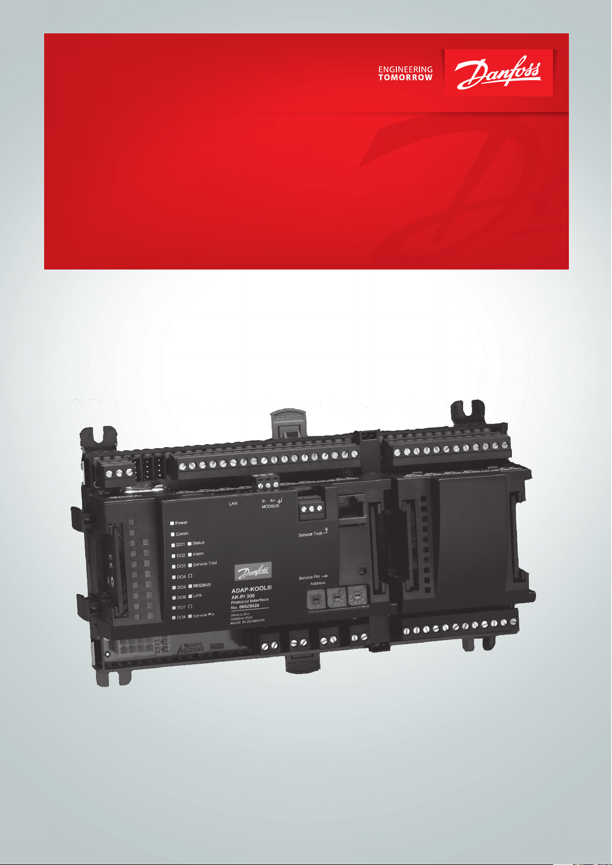
The AK-PI 300 is an intermediary link allowing Daikin type
controllers to be operated via a System Manager, e.g. AK-SM 720
or similar.
The actual operation of the controllers is carried out with an AK-ST
500.
Daikin units include data communication, where communication
is controlled by a Daikin Comm. box or a Daikin RTD-network.
The three units: “Outdoor unit”, “Booster unit” and “Indoor unit”
can be connected to the Comm. box and “Indoor unit” to RTDnetwork.
Application
The AK-PI 300 is used on systems where the system unit is an
AK-SM 720 and where there is/are one or more Daikin type units.
AK-PI 300 links communication to Daikin so that the system
manager can present all the controllers on the system.
Daikin units are presented on an equal footing together with
LON RS 485 controllers and MODBUS controllers.
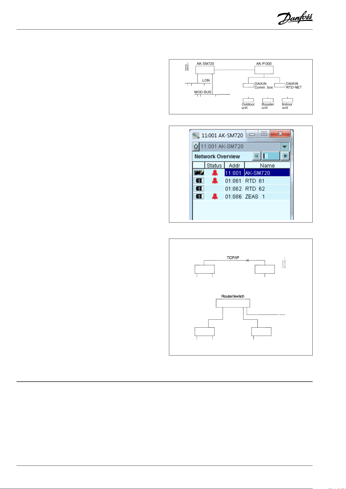
All controllers can be viewed and operated from the system
manager’s network overview.
The network list on the right shows two RTD-networks, and an
outdoor unit. The outdoor unit is connected via a Comm. box.
Principle
The link between the system manager and the AK-PI 300 is via a
TCP/IP.
In this very simple connection the two units can be connected to
each other via a crossed cable.
This is where the IP addresses are set to static addresses.
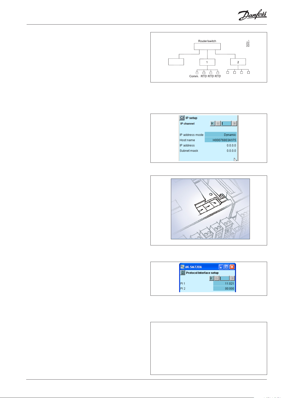
On larger systems or where there is also outgoing IP
communication from the system, the connection must be made
via a router.
Here the IP addresses can be dynamic, but if there is
communication to the system from outside, they must be static.
If you are not sure whether you should select static or dynamic, abide
by the following recommendation:
Dynamic is the easiest. Here the router itself allocates an address
for the system manager and another for the PI unit. But you
should only select this solution if the system is closed without a
connection for an external operation interface.
With static you must obtain a couple of addresses yourself at the
local IT department and you must also set the addresses yourself
in the two units. This solution must always be used when the
system is operated by an external service company, e.g. for log
collection, alarm management or service.
Contents
Introduction ....................................................................................................... 2
Installation .......................................................................................................... 4
Requirements and terms ............................................................................... 6
Ordering .............................................................................................................. 8
Data ....................................................................................................................... 8
2 Manual RS8GP102 © Danfoss 12-2015 AK-PI 300
Page 3
Number of Daikin units
One Comm. box and three RTD units can be connected to a single
AK-PI 300.
If there are more, use 2 (x) AK-PI 300 units.
Up to two AK-PI-300 units can be connected to a single system
manager, i.e. up to 2 Comm. boxes and 6 RTD units.
If there are two AK-PI 300 units, the connection to the system
manager is led via a router or a switch.
(Up to 32 outdoor units, 30 booster units and 64 indoor units can
be connected to a single Comm. box. Up to 16 indoor units can be
connected to a single RTD unit.)
Addresses
In principle there are three types of addresses:
IP addresses
Both the system manager and the AK-PI 300 must have an IP
address set.
The address can be either dynamic or static – the desired value is
selected with a setting. If static is chosen, an address must also be
set.
If the system can be accessed externally, the setting in the
system manager AK-SM 720 must always be set to static so that
the external connection always recognises the address and can
communicate with the unit.
(The IP address is set in a menu).
Network addresses
There must always be one and only one master system manager
on a network. This is dened with the address setting = 1. This
system manager controls the communication to all the other
controllers on the network. The PI unit is perceived as a controller
on the network and its address can be viewed in the IP list. (Up to
two PI units can be connected to the system manager, which is
master - i.e. has address =1)
(You set the network address on the front of the system units and
on the front of the PI units.)
Set the system manager to address 1.
If there are several system managers (slave network), set these to
addresses 2 to 10.
Each PI unit is set with a separate address. Select 12 or higher, e.g.
21.
Interconnection
When setting the system manager, a menu must also be set in
which the relevant AK-PI 300 chooses the network. The system
manager then knows the way to the dierent Daikin units. The
system manager must be version 1.20 or later.
Controller addresses
All controllers on the same network must have dierent addresses.
In other words, all controllers that are connected to a system
manager on either:
• the LON communication
• the MODBUS communication
• the DANBUSS communication or
• Daikin communication.
Start with the addresses on Daikin RTD-NET.
Then for DANBUSS, if needed (via AK-PI 200).
A Daikin Comm. box registers 3 addresses.
After this, add the addresses on the Daikin Comm. box connections. (These address numbers can be oset. See next page.)
The addresses on the LON and MOD buses can be set higher.
No more than 200 controllers can be connected to a system
manager.
Daikin Outdoor: Address options 1 to 32
Daikin Booster: Address options 1 to 30
Daikin Indoor: Address options 1 to 64
DANBUSS communication: Address options 1 to 120
LON-communication: Address options 1 to 999
MOD-bus communication: Address options 1 to 247
Max. number of controllers: 200 pcs.
AK-PI 300 Manual RS8GP102 © Danfoss 12-2015 3
Page 4

Installation
Preparing addresses on the Daikin-network
Note down which addresses the units have,
e.g.:
Outdoor = 6
Booster = 1
Indoor = 2
These must be adapted in order to prevent these addresses from
conicting with each other and other controller addresses on the
network overview. Duplication of addresses is not permitted.
Set a value for the Comm. box connections that will increase the
address value so as to prevent duplication.
E.g. 100, 200 and 300, as shown in the image on the right.
The values constitute factory default settings.
In the network overview they will subsequently be shown as
oset by either:
100 for outdoor (displayed as 106)
200 for booster (displayed as 201)
300 for indoor (displayed as 302).
RTD = 9600
Only via Comm. box
Only via Comm. box
Only via Comm. box
Note
• The address of Comm. box will take up 3 addresses, the set address and the
two subsequent ones.
• RTD can only run at 9600 baud.
• Omit indoor units on Comm. box: If an indoor unit is connected to both an
RTD and outdoor unit, the scanning of indoor units on the Comm. box can
be deselected. Otherwise, they will appear twice in the system.
Preparing TCP/IP connection
The AK-PI 300 must have a connection to the system manager –
both physically and with a software setting. This can take place in
one of the following ways:
1. Connection
a) Direct connection (only used if there is not an external
connection via a router).
The cable between the two units must be a crossed cable.
(A static IP address is always used here.)
b) Cables from the units are connected to a router or to a switch.
(A dynamic or static IP address is used here.)
2. Setting
a) Router
- Dynamic: There are no settings in the router
- Static: A static address range must be set in the router
b) AK-SM 720
- Select static if the connection between the system unit and
the AK-PI 300 is with a crossed cable or there is an external
connection to the system. Then set the IP address (an IP
address must be obtained from the local IT manager).
- Select dynamic if it is a closed system and the two units are
connected to a router or a switch.
c) In the AK-PI 300 the IP address is set either to static or to
dynamic.
- Select static if the connection between the system unit and
the AK-PI 300 is with a crossed cable. Then set the IP address
(an IP address must be obtained from the local IT manager).
- Select dynamic if it is a closed system and the two units are
connected to a router or a switch.
1a)
1b)
Crossed cable
3. If a router or switch is connected, it must be turned on.
4 Manual RS8GP102 © Danfoss 12-2015 AK-PI 300
Page 5

Preparing the system manager
1. Set its address on the front to 1 (there must always be a system
manager with address 1 on a network (1=master)). If there are
several networks and thus several system managers, they must
have addresses 2 to 10.
2. Connect the controllers to the two data communications, LON
and MODBUS. Switch on the controllers and set an address in
each controller. Addresses may not be duplicated – not even
with addresses on the Daikin-NET, the Comm. box’s 3 addresses
or the addresses adjusted with an oset.
3. Apply power to the system manager
4. If a static IP address is used, this must be set
5. Enter the system manager's service PIN
Preparing the AK-PI 300
1. Set its address on the front (e.g. to 12)
(possible range = 11-999)
2. Apply the power
3. If a static IP address is used, this must be set
4. (You can activate the “Service PIN” function at this point.
If you do, this means you do not have to start the scan function
in the next point.)
Perform the rst scan
1. Start the scan function in the system manager – wait for the
results
(the controllers on the LON and MODBUS communication will
now be located and visible in the network overview).
2. Go to the next page of the network overview, which details the
IP registrations.
Check that the AK-PI 300 unit is registered.
Interconnection
Dene which AK-PI 300 unit the system manager should recognise
(several units can be registered but the system manager with
address 1 can only control two units.
1. There is a menu in the system manager in which settings must
be entered. Go to the Setup menu/Protocol interface (the
system manager must be version 1.20 or later).
2. Select the address of the AK-PI 300, which is to be connected to
the system unit.
Perform scan number 2 and locate the Daikin units
Precondition:
Daikin units must be connected to AK-PI 300 on the Modbus terminals. (This output is adapted to the Daikin Modbus Protocol and
can only be used for Daikin units.)
1. Perform a new scan of the system manager. Wait for the results.
(All controllers will now be located.)
Se manualen for systemmanageren for yderligere installation.
Daikin units
AK-PI 300 Manual RS8GP102 © Danfoss 12-2015 5
Page 6

Requirements and terms
Principle
• The installation of the data communication must be carried out
as specied in the guide to the RC8AC.
• The terminations must be in order.
• Up to 1 Comm. box + 3 RTD-network units can be connected to
a single AK-PI 300 unit.
• Up to two AK-PI 300 units can be connected to a single
system manager.
• Only addresses on the Comm. box can be oset.
• Furthermore, address numbers on an RTD-network must not also
be address numbers on an AK-SM 720 unit.
• A Comm. box registers 3 addresses on the Daikin Modbus network: the one it is set with + the 2 subsequent ones. The units
on an RTD-network must not have an address that coincides
with these 3 addresses.
• Network addresses
Here is a small summary of the networks and addresses that can
occur:
11:001 is the master system manager
11:002 to 11:010 are slave networks controlled by 11:001
(the gure “11” keeps track of the networks and cannot be
changed).
11:012 to 11:999 are addresses for units on the network. The
units can be AK-PI 300 units or wireless units, or they can be
controllers in which the data communication takes place via
TCP/IP.
1: xxx will be controllers that are registered under the master
system manager.
2: xxx will be controllers that are registered under slave network
number 2.
6 Manual RS8GP102 © Danfoss 12-2015 AK-PI 300
Page 7

The overview display will show the following:
• The address of the system manager that AK-PI 300 is connected
to
• The status of the alarm transmission
• Date and time
• The quality of the Daikin communication signal
The conguration display gives access to the following:
• The conguration lock is only used if a static IP address is to be
set.
• Under "System setup" you can give the unit a name
• IP settings can be entered
Examples of IP addresses
AK-PI 300 Manual RS8GP102 © Danfoss 12-2015 7
Page 8

Ordering
Type Function Application Language Code no.
AK-PI 300 Protocol interface
Accessories Transformer module 230 V / 115 V to 24 V
AK-PS 075 18 VA Supply 080Z0053
Intermediary link between system manager and units with
Daikin data communication
English, German, 080Z8526
Data
Supply voltage 24 V a.c. +/- 20%
Power consumption AK-PI 300 12 VA
Ambient temperature During transport -40 to 70°C
During operation -20 to 55°C ,
0 to 95% RH (non condensing)
No shock inuences / vibrations
Enclosure Material PC / ABS
Enclosure IP10 , VBG 4
Mounting For mounting on wall or DIN rail
Weight Approx. 600 g
Approvals EU low voltage directive and EMC require-
ments are complied with
UL 873,
LVD tested according to EN 60730
EMC tested
Immunity according to EN 61000-6-2
Emission according to EN 50081-1
UL le number: E166834
Danfoss can accept no responsibility for possible errors in catalogues, brochures and other printed material. Danfoss reserves the right to alter its products without notice. This also applies to products
already on order provided that such alternations can be made without subsequential changes being necessary in specications already agreed.
All trademarks in this material are property of the respecitve companies. Danfoss and Danfoss logotype are trademarks of Danfoss A/S. All rights reserved.
8 Manual RS8GP102 © Danfoss 12-2015 AK-PI 300
ADAP-KOOL®
 Loading...