

Page 1

User Guide
Woodley Protokol interface
AK-PI 100
ADAP-KOOL® Refrigeration control systems
Page 2
Introduction
Function
The AK-PI 100 is an intermediary link allowing Woodley type units
to be operated by an AK-SC 255 system controller.
This way of operating the Woodley units replaces the previous
Woodley S5 operating interface.
Application
The AK-PI 100 is used on systems with an AK-SC 255 system controller, but which still contain older Woodley type units.
These types can be:
• Woodley MDM units
• Woodley 4 way TPI cards
• Older units connected to the WTP bus (WTP = Woodley Third
Party)
Measurements and status readings from the individual Woodley
units are uploaded to the AK-PI 100 and on to the AK-SC 255,
where the data is presented in the same way as other ADAPKOOL(r) units.
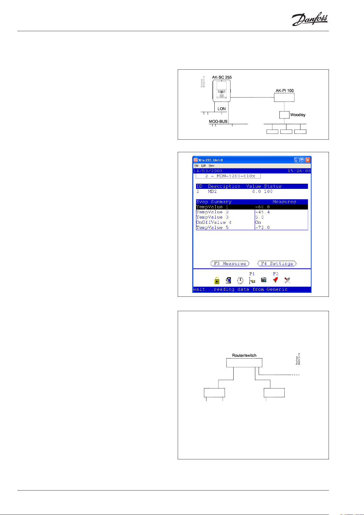
Principle
The AK-SC 255 and the AK-PI 100 are linked by Ethernet.
For a straightforward connection, the two units can be linked by a
switch.
In this case, the IP addresses are set to static addresses. You can
choose any addresses, but only if nothing else is connected.
(It is easiest to use a router and dynamic address allocation. In this
case, the router allocates one address to the AK-SC 255 and another to the PI unit. You can only use this solution if the system is
self-contained with no contact to an external operating interface.)
In larger systems or if IP communication takes place from the system, the connection must be based on a router or a switch.
If a router is used, the IP address of the AK-PI 100 may be dynamic,
but the address of the AK-SC 255 must be static.
If a switch is used, both must be static.
You will need to request static addresses from the IT department
yourself, and then congure the addresses in both units. You
should always use this solution if the system is accessed by an
external service company, for example for log extraction, alarm
handling or servicing.
2 Manual RS8FB102 © Danfoss 03-2008 AK-PI 100
Page 3
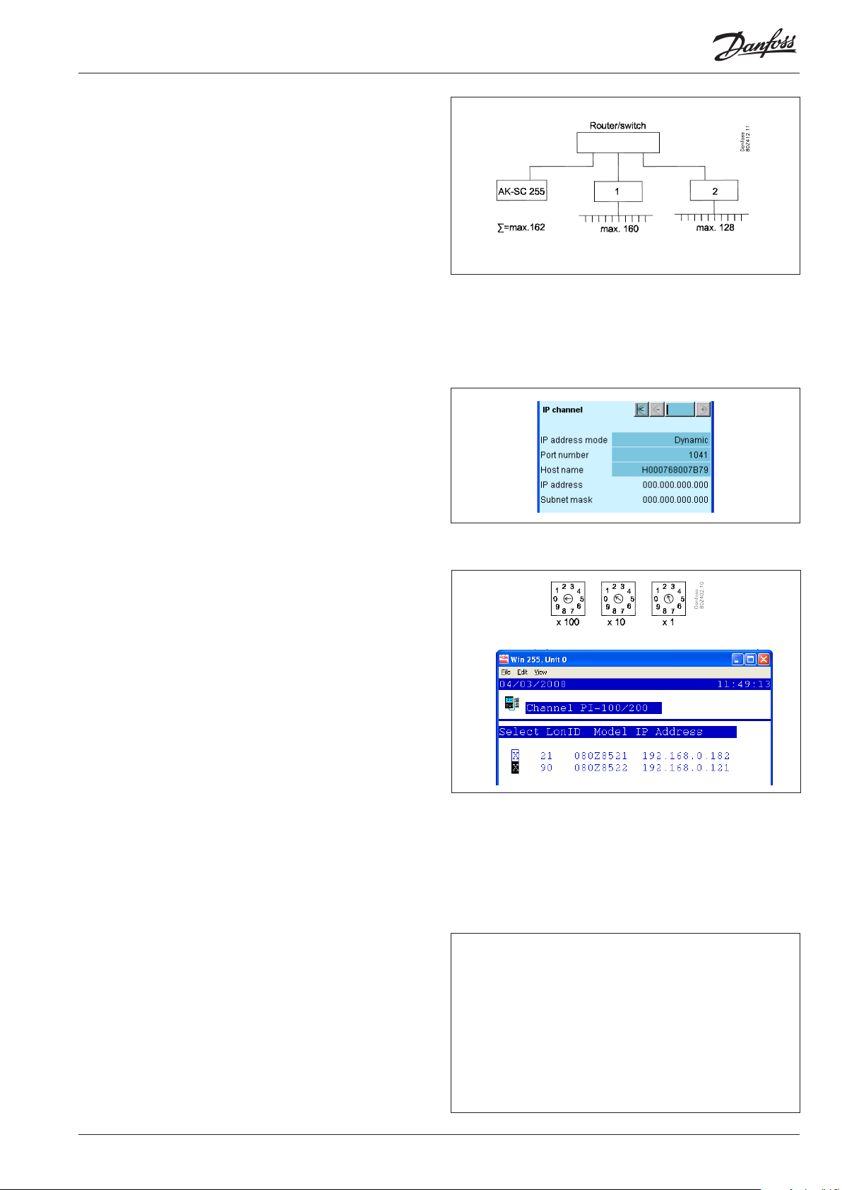
Communication/number of addresses
An AK-PI 100 can be congured for two types of communication
- MDM communication or WTP communication. If both types of
communication are needed in the system, two AK-PI 100 units
must be used.
With MDM communication, up to 160 controllers can be connected to one AK-PI 100.
With WTP communication, up to 128 controllers can be connected
to one AK-PI 100.
In total, the AK-SC 255 can handle up to 162 addresses, including
units connected directly to the system controller.
Addresses
In principle, there are three types of address:
IP addresses
An IP address must be congured for the system controller and for
the AK-PI 100.
The address can be either static or dynamic - the choice is made
by changing a setting. To use a static address, you also need to
congure the address.
If the system is accessed from the outside, the system controller
should always be set to static, so that the external connection
always knows the address and is able to contact the unit.
(The IP is congured using a menu.)
Network addresses
A network must always have one, and only one, unit acting as
master. In this case, the master is AK-SC 255. To specify this, the
address is congured to = 0. This master controls communication
with all other controllers in the network.
A PI unit is handled as a controller in the network, and you can
view its address in the “Channel PI-100/200” screen.
Each PI unit is congured with a dierent address. You can choose
11, 12 or above, e.g. 21. (Addresses 1 to 10 are reserved for subnets.)
Connection:
When you congure the system controller, the relevant AK-PI 100
is assigned to the network. The system controller then recognises
the link to all the MDM units/WTP units. The check marks in the
screenshot on the right show that contact with PI units has been
selected. One has the address 21 and the other has the address 90
(the numbers 084Z8521 and 22 indicate that there is one PI 200
and one PI 100).
Controller addresses
All controllers in the same network must have dierent addresses.
This means all controllers connected to a system controller via:
• LON communication
• MOD bus communication
• DANBUSS communication via an AK-PI 200
• MDM communication via an AK-PI 100
• WTP communication via an AK-PI 100
A maximum of 162 controllers can be connected to a system controller. The system controller cannot handle addresses above 199.
The AK-PI 100 has an auxiliary function that can shift a group of
addresses, so that you do not need to change the address in each
individual MDM and WTP unit.
The function is called “address oset”, and informs the AK-SC 255
of the changed addresses. After the function, a unit has the following address: Oset value + congured address of the unit.
DANBUSS communication: Address options 1 to 120
LON communication: Address options 1 to 199
MOD bus communication: Address options 1 to 199
MDM communication: Address options 1 to 199 (255)
WTP communication: Address options 1 to 199 (248)
AK-SC 255: Address options 1 to 199
Max. number: 162
AK-PI 100 Manual RS8FB102 © Danfoss 03-2008 3
Page 4

Installation
Preparing the TCP/IP connection
The AK-PI 100 must be linked to the AK-SC 255 physically and also
with a software setting. You can do this as follows:
1. Connection
Cables are run from the units to a router or to a switch.
2. Setting
a) Router
- Dynamic: If DHCP is enabled, no settings need to be
changed in the router
- Static: Check that the static address range does not conict
with the DHCP range
b) Switch
No direct settings are necessary, but addresses are always
static for AK-SC 255 and AK-PI 100
c) AK-SC 255
- Choose static if the AK-SC 255 and AK-PI 100 are connected
by a switch or if the system can be accessed from outside.
Then congure the IP address (request an IP address from
the IT ocer of the department).
- Select dynamic if the system is self-contained and both units
are connected to a router.
d) In the AK-PI 100, set IP addressing to either static or dynamic.
- Choose static if the AK-SC 255 and AK-PI 100 are linked by a
switch. Then congure the IP address (request an IP address
from the IT ocer of the department).
- Select dynamic if the system is self-contained and both units
are connected to a router.
3. If a router or switch is connected, turn it on.
AK-PI 100 conguration
1. Set the address on the front to 0 (0 is the factory setting)
2. Switch on
3. Attach the service tool (the service tool can only be used if the
address is set to 0)
4. Set AK-PI 100
a. Press the service key button
b. Unlock the conguration
c. Select System setup
d. Enter a name for the controller (the name cannot be seen
outside the PI unit yet)
e. Select the protocol you want to use (MDM or WTP)
f. Select whether you want to use the “Address oset” function
g. Switch to IP setup if you are using a static IP address.
Congure the address
h. Lock the conguration
5. Disconnect the service tool
6. Set the address on the front (for example to 12).
The address range is between 11 and 199.
4 Manual RS8FB102 © Danfoss 03-2008 AK-PI 100
Page 5

Connect the units
AK-SC 255: Attach the connector to the Ethernet connector.
AK-PI 100: The connection to the AK-SC 255 (switch/router) must use the
“LAN” connector.
AK-SC 255 settings
Dene the IP setup
Switch to the displayed screen with:
Communications / Internet / Cong
Set
• DHCP to Yes for Dynamic IP
If necessary
• Congure the mask
If necessary
• Congure the IP address
AK-PI 100: The connection to the Woodley unit must use the
connector for the “Service tool”.
Scanning for IP addresses and Woodley units
Switch to the displayed screen with:
Communications / I/O Network / Rescan channels
• Select the “Channel PI-100/200” eld
• Activate the “Rescan Network” function
• Click the “PI-100/200” button to switch to the next screen
• Select the addresses to be contacted (addresses 21 and 90
are shown here)
• Go back to the previous screen
• Activate the “Rescan Network” function
AK-PI 100 Manual RS8FB102 © Danfoss 03-2008 5
Page 6

Dene the setup of the Woodley units
Switch to the displayed screen with:
Communications / Refrigeration / Add Controls
Specify the description le:
• Select No for “Pack controller”
• Select the number of controllers (in this example 10)
• Click the “Setup” button to switch to the next screen
• Click “Edit” on the rst controller type (in the “Type” eld)
• Select the description le matching the controller.
Congure the data in the unit:
• Go back to the overview screen for all Woodley units
• Press “Setup” for the relevant controller type
• Set the address. This is the address the unit is set to + any
“address oset value”
• Edit the name if necessary
• Change the settings.
All controller types and software versions will require a
description le. Select the relevant le.
If the le is not listed, it must be uploaded to the AK-SC 255.
Contact Danfoss.
6 Manual RS8FB102 © Danfoss 03-2008 AK-PI 100
Page 7

Overview of functions in the
AK-PI 100
The overview display will show the following:
• Status of alarm transmission
• Date and time
• Quality of the signal for communication with the Woodley MDM
unit or to Woodley TPI unit (the value is always 0 if the service
tool is attached).
The conguration display gives access to the following:
• The conguration lock is used with the following settings:
- Communication setting (MDM or WTP)
- Address oset setting (addresses are congured for all units on
the communication line. If these address values conict with
other addresses, the entire connected group can be “oset”. For
example a group of units has the addresses 20 to 31. By setting
“Address oset” to 50, the address will become 70 to 81 in the
AK-SC 255. This removes the need to change the addresses of
the existing units).
- Adjustment of a static IP address.
• In “System setup” you can give the unit a name
• You can change the IP setup
Examples of controller addresses
Example of IP addresses
AK-PI 100 Manual RS8FB102 © Danfoss 03-2008 7
Page 8
Ordering
Type Function Application Language Code no.
AK-PI 100 Protokol interface
Accessories Accessories Transformer module 230 V / 115 V to 24 V
AK-PS 075 18 VA Supply 080Z0053
- RS 232 cable between AK-PI 100 and Woodley MDM / 4 way TPI card 080Z0263
Intermediary link between System controller AK-SC 255 and
Woodley controllers. The unit makes is possible to change the
user interface from Woodley's S5 to Danfoss' AK-SC 255
English, French, 080Z8522
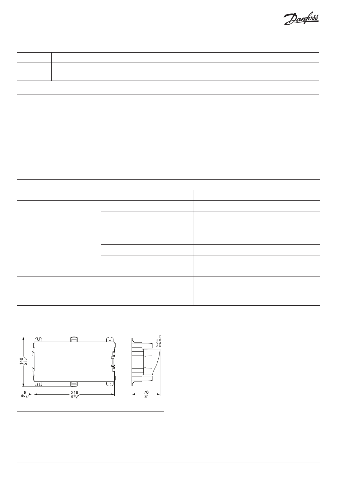
Data
Supply voltage 24 V AC. +/- 20%
Power consumption AK-PI 100 8 VA
Ambient environment During transport -40 to 70°C
During operation -20 to 55°C ,
Enclosure Material PC / ABS
Protection IP10 , VBG 4
Installation Built in. On panel wall or DIN rail
Weight Ca. 600 g
Approvals EU low voltage directive and EMC require-
ments are complied with
0 to 95% RH (non condensing)
No shock inuences / vibrations
LVD tested to EN 60730
EMC tested
Immunity to: EN 61000-6-2
Emission to: EN 61000-6-3
Danfoss can accept no responsibility for possible errors in catalogues, brochures and other printed material. Danfoss reserves the right to alter its products without notice. This also applies to products
already on order provided that such alternations can be made without subsequential changes being necessary in specications already agreed.
All trademarks in this material are property of the respecitve companies. Danfoss and Danfoss logotype are trademarks of Danfoss A/S. All rights reserved.
8 Manual RS8FB102 © Danfoss 03-2008 AK-PI 100
DE-DB
 Loading...