

Page 1
User Guide
Pack controller
Type AK-PC 782A
Capacity controller for transcritical CO2 booster control
SW Ver. 3.5x
www.danfoss.com
Page 2

User Guide | Pack controller, type AK-PC 782A
Contents
1. Introduction ............................................................................3
1.1 Application ...........................................................................................3
1.2 Principles ..............................................................................................4
2. Design of a controller .............................................................7
2.1 Module survey ....................................................................................7
2.2 Common data for modules ......................................................... 10
2.3 Controller ........................................................................................... 11
2.3.1 Extension module AK-XM 101A ...................................13
2.3.2 Extension module AK-XM 102A / AK-XM 102B ......15
2.3.3 Extension module AK-XM 103A ...................................17
2.3.4 Extension module AK-XM 204A / AK-XM 204B ......19
2.3.5 Extension module AK-XM 205A / AK-XM 205B ......21
2.3.6 Extension module AK-XM 208C ................................... 23
2.3.7 Extension module AK-OB 110 ...................................... 25
2.3.8 Extension module EKA 163B / EKA 164B .................. 26
2.3.9 Graphic display MMIGRS2 ............................................. 26
2.3.10 Power supply module AK-PS 075 / 150 / 250..........27
2.3.11 Communication module AK-CM 102 ......................... 28
2.4 Preface to design ............................................................................ 29
2.5 Design of a compressor and condenser control .................31
2.6 Ordering ............................................................................................. 39
3. Mounting and wiring ............................................................40
3.1 Mounting ........................................................................................... 40
3.2 Wiring ................................................................................................. 42
4. Configuration and operation ...............................................45
4.1 Configuration ................................................................................... 45
4.1.1 Connect PC.......................................................................... 45
4.1.2 Authorization ..................................................................... 47
4.1.3 Unlock the configuration of the controllers ............48
4.1.4 System set-up .....................................................................49
4.1.5 Set plant type ..................................................................... 50
4.1.6 Set control of suction group MT ..................................51
4.1.7 Set oil management ........................................................ 55
4.1.8 Set up control of condenser fans ................................ 56
4.1.9 Set-up of high pressure control ................................... 58
4.1.10 Set up control of receiver pressure.............................59
4.1.11 Set-up Receiver Reference with
Low Pressure Multi Ejectors ......................................... 62
4.1.12 Set up control of heat recovery ................................... 63
4.1.13 Set up KPI and COP calculation ................................... 65
4.1.14 Set up Display .................................................................... 66
4.1.15 Set-up Functions for General purpose ...................... 67
4.1.16 Separate thermostats ...................................................... 68
4.1.17 Separate pressostats ........................................................68
4.1.18 Separate voltage signals ................................................ 69
4.1.19 Separate alarm inputs ..................................................... 69
4.1.20 Separate PI functions ...................................................... 70
4.1.21 Configuration of inputs and outputs .........................71
4.1.22 Set alarm priorities ........................................................... 73
4.1.23 Lock configuration ........................................................... 74
4.1.24 Check configuration ........................................................ 75
4.2 Check of connections .................................................................... 77
4.3 Check of settings............................................................................. 79
4.4 Schedule function .......................................................................... 81
4.5 Installation in network .................................................................. 82
4.6 First start of control ........................................................................ 83
4.6.1 Start the control ................................................................ 84
4.6.2 Manual capacity control ................................................. 85
5. Regulating functions ............................................................86
5.1 Suction group .................................................................................. 86
5.2 Capacity control of compressors...............................................87
5.2.1 Capacity distribution methods .................................... 89
5.2.2 Power pack types – compressor combinations ..... 90
5.2.3 Compressor timers ........................................................... 94
5.2.4 Compressor with variable capacity ............................ 94
5.2.5 Load shedding ................................................................... 96
5.2.6 Injection ON ........................................................................ 96
5.2.7 Liquid injection in common suction line ................. 97
5.2.8 Safety functions ................................................................. 98
5.3 Oil management ...........................................................................100
5.4 Condenser / Gas cooler ..............................................................102
5.4.1 Capacity control of condenser ...................................102
5.4.2 Reference for gas cooler temperature ....................102
5.4.3 Capacity distribution .....................................................104
5.5 Condenser couplings ..................................................................105
5.6 Safety functions for condenser ................................................105
5.7 CO transcritical system and heat recovery .........................106
5.7.1 Circuit for heat recovery or hot tap water..............107
5.7.2 Circuit for recovery for heating ..................................108
5.7.3 Circuits for control of CO gas pressure ..................112
5.7.4 Ejector control ..................................................................114
5.7.5 Receiver control ...............................................................118
5.7.6 Safety procedures ..........................................................119
5.7.7 Actions on low receiver pressure .............................120
5.7.8 Parallel Compression ....................................................121
5.8 Setpoint Management ................................................................125
5.9 General monitoring functions .................................................129
5.10 Miscellaneous ................................................................................131
5.11 KPI and COP calculations ...........................................................136
5.12 Appendix A –
Compressor combinations and coupling patterns...........138
5.13 Appendix B – Alarm texts .......................................................... 144
2 | BC245386497365en-000801 © Danfoss | Climate Solutions | 2022.02
Page 3
User Guide | Pack controller, type AK-PC 782A
1. Introduction
1.1 Application
AK-PC 782A are complete regulating units for capacity control of
compressors and condensers in a transcritical CO booster system
with parallel compressor. The controller is with oil management,
heat recovery function and CO gas pressure control.
In addition to capacity control, the controllers can give signals to
other controllers about the operating condition, e.g. forced closing
of expansion valves, alarm signals and alarm messages.
The controller’s main function is to control compressors and
condensers so that operation all the time takes place at the
energy-optimum pressure conditions. Both suction pressure
and condensing pressure are controlled by signals from pressure
transmitters.
Capacity control must be carried out by suction pressure P0. (The
P0 signal for the parallel compressor is supplied by the pressure
transmitter on the receiver).
Among the different functions are:
• Capacity control of up to 10 compressors on MT and 8 on IT
• Capacity control of up to 4 compressors on LT
• Up to 3 unloaders for each compressor
• Control of oil separator and oil receiver
• Speed control of one or two compressors in each group
• Up to 6 safety inputs for each compressor
• Option for capacity limitation to minimize consumption peaks
• If the compressor does not start, signals can be transmitted to
other controllers so that the electronic expansion valves will be
closed
• Regulation of liquid injection into suction line
• Safety monitoring of high pressure / low pressure / discharge
temperature
• Capacity control of up to 8 fans
• Floating reference with regard to outside temperature
• Heat recovery function
• CO gas cooler control and receiver control
• Ejector regulation: HP, LE (liquid)
• Safety monitoring of fans
• The status of the outputs and inputs is shown by means of lightemitting diodes on the front panel
• Alarm signals can be generated via data communication
• Alarms are shown with texts so that the cause of the alarm is
easy to see.
• Plus some completely separate functions that are totally
independent of the regulation – such as alarm, thermostat,
pressure and PI-regulating functions.
SW = 3.5x
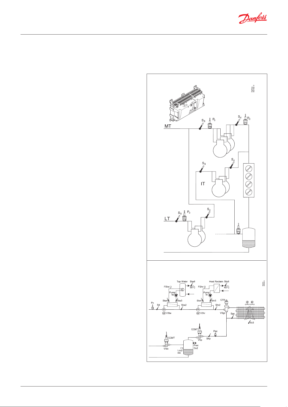
Examples
Traditional capacity control
Prec
Heat recovery functions, controlling the condensing pressure and
receiver pressure
© Danfoss | Climate Solutions | 2022.02 BC245386497365en-000801 | 3
Page 4
User Guide | Pack controller, type AK-PC 782A
1.2 Principles
The great advantage of this series of controllers is that it can
be extended as the size of the plant is increased. It has been
developed for refrigeration control systems, but not for any
specific application – variation is created through the read-in
software and the way you choose to define the connections.
The same modules that are used for each regulation and the
composition can be changed, as required. With these modules
(building blocks) it is possible to create a multitude of various
kinds of regulations. But it is you who must help adjusting the
regulation to the actual needs – these instructions will assist you to
find your way through all the questions so that the regulation can
be defined and the connections made.
Controller
Top part
Bottom part
The controller is the cornerstone of the regulation. The module has
inputs and outputs capable of handling small systems.
• The bottom part – and hence the terminals – are the same for all
controller types.
• The top part contains the intelligence with software. This unit will vary
according to controller type. But it will always be supplied together
with the bottom part.
• In addition to the software, the top part is provided with connections
for data communication and address setting.
Advantages
• The controller’s size can “grow” as systems grow
• The software can be set for one or more regulations
• Several regulations with the same components
• Extension-friendly when systems' requirements are changed
• Flexible concept:
– Controller series with common construction
– One principle – many regulation uses
– modules are selected for the actual connection requirements
– The same modules are used from regulation to regulation
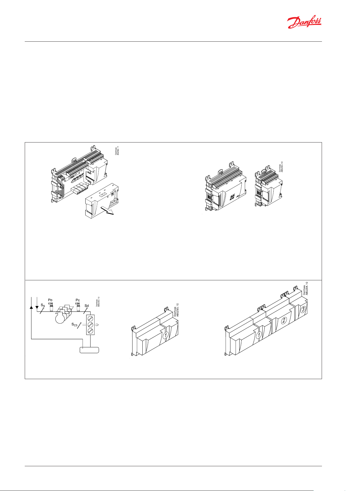
Extension modules
If the system grows and more functions have to be controlled, the
regulation can be extended.
With extra modules more signals can be received and more relays cut in
and out – how many of them – and which – is determined by the relevant
application.
Examples
A regulation with few connections
can be performed with the controller
module alone.
If there are many connections, one or more
extension modules have to be mounted.
4 | BC245386497365en-000801 © Danfoss | Climate Solutions | 2022.02
Page 5
User Guide | Pack controller, type AK-PC 782A
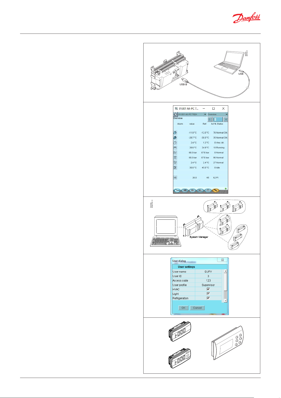
Direct connection
Setup and operation of an AK controller must be accomplished via
the “AK-Service Tool” software program.
The program is installed on a PC, set up and operation of the
various functions is carried out via the controller’s menu displays.
Displays
The menu displays are dynamic, so that different settings in one
menu will result in different setting possibilities in other menus.
A simple application with few connections will give a set-up with
few settings.
A corresponding application with many connections will give a
set-up with many settings.
From the overview display there is access to further displays for
the compressor regulation and the condenser regulation.
At the bottom of the display there is access to a number of general
functions, such as “time table”, “manual operation”, “log function”,
“alarms”, and “service” (configuration).
Network linking
The controller can be linked up to a network together with other
controllers in an ADAP-KOOL® refrigeration control system. After
the set-up, operation can be performed at a distance with e.g. our
software program type AKM.
Users
The controller comes supplied with several languages, one of
which can be selected and employed by the user. If there are
several users, they may each have their choice of language. All
users must be assigned a user profile which either gives access to
full operation or gradually limits the operation to the lowest level
that only allows you “to see”.
Language selection is part of the Service Tool settings.
If the language selection is not available in the Service Tool for the
current regulator, English texts will be displayed.
External display
An external display can be fitted in order for P0 (Suction) and Pc
(Condensing) readings to be displayed.
A total of 4 displays can be fitted and with one setting it is possible
to choose between the following readings: suction pressure,
suction pressure in temperature, Ss, Sd, condenser pressure,
condenser pressure in temperature, S7 gas cooler temperature,
hot tap water at heat recovery and heat exchanger temperature at
heat recovery.
A graphical display with control buttons can also be fitted.
© Danfoss | Climate Solutions | 2022.02 BC245386497365en-000801 | 5
Page 6
User Guide | Pack controller, type AK-PC 782A
Light-emitting diodes
A number of light-emitting diodes makes it possible to follow the
signals that are received and transmitted by the controller.
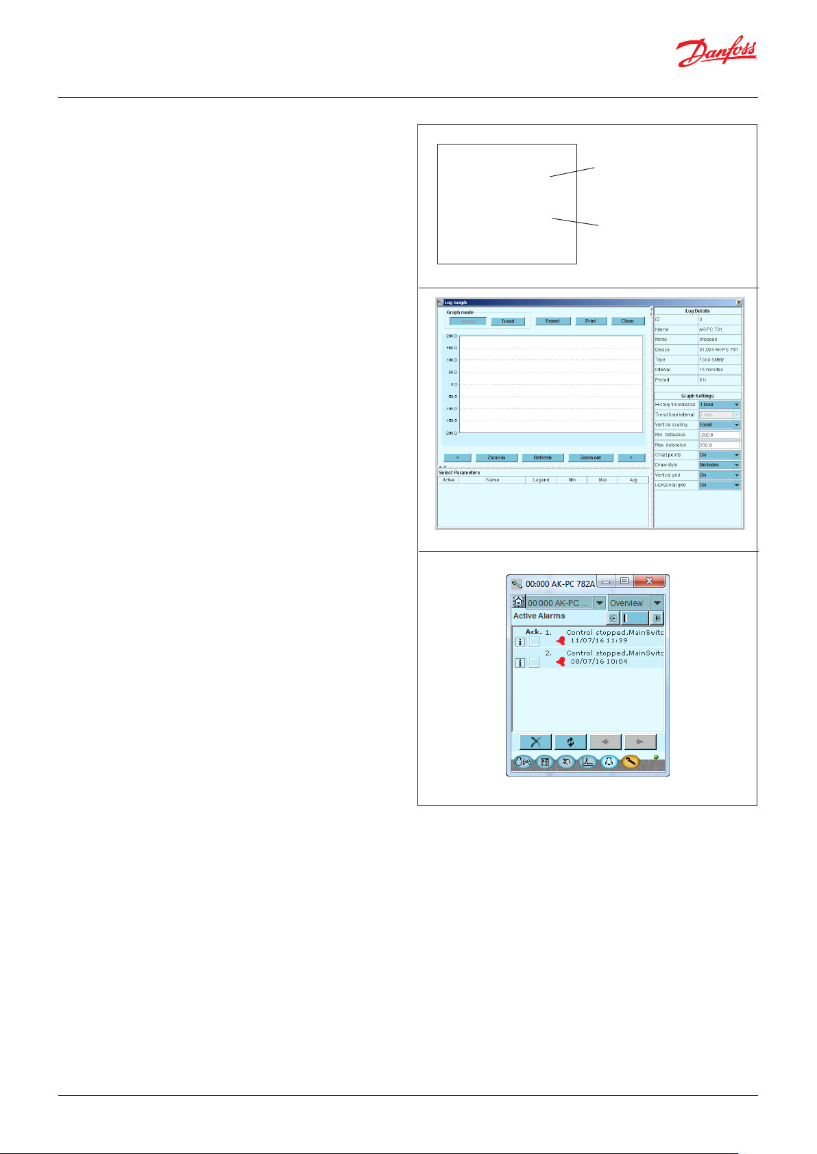
Log
From the log function you can define the measurements you wish
to be shown.
The collected values can be printed, or you may export them to a
file. You can open the file in Excel.
If you are in a service situation, you can show measurements in a
trend function. The measurements are then made real-time and
displayed instantly.
n Power
n Comm
n DO1 n Status
n DO2 n Service Tool
n DO3 n LON
n DO4 n I/O Extension
n DO5 n Alarm
n DO6
n DO7 n Display
n DO8 n Service Pin
Slow flash = OK
Quick flash = answer from gateway
Constantly ON = error
Constantly OFF = error
Flash = active alarm/not cancelled
Constant ON = Active alarm/cancelled
Alarm
The display gives you an overview of all active alarms. If you wish
to confirm that you have seen the alarm you can cross it off in the
acknowledge field.
If you want to know more about a current alarm you can click on it
and obtain an information display on the screen.
A corresponding display exists for all earlier alarms. Here you can
upload information if you need further details about the alarm
history.
6 | BC245386497365en-000801 © Danfoss | Climate Solutions | 2022.02
Page 7

User Guide | Pack controller, type AK-PC 782A
2. Design of a controller
This section describes how the controller is designed.
The controller in the system is based on a uniform connection
platform where any deviations from regulation to regulation is
determined by the used top part with a specific software and
which input and output signals the relevant application will
require. If it is an application with few connections, the controller
2.1 Module survey
Controller module – capable of handling minor plant
requirements.
Extension modules
When the complexity becomes greater and additional inputs or
outputs are required, modules can be attached to the controller.
A plug on the side of the module will transmit the supply voltage
and data communication between the modules.
Top part
The upper part of the controller module contains the intelligence.
This is the unit where the regulation is defined and where data
communication is connected to other controllers in a bigger
network.
Connection types
There are various types of inputs and outputs. One type may, for
example, receive signals from sensors and switches. Another may
receive a voltage signal, and a third type may be outputs with
relays etc. The individual types are shown in the table below.
module (top part with belonging bottom part) may be sufficient.
If it is an application with many connections, it will be necessary to
use the controller module plus one or more extension modules.
This section will give you a survey of possible connections plus
assistance in selecting the modules required by your actual
application.
Optional connection
When a regulation is planned (set up), it will generate a need for a
number of connections distributed on the mentioned types. This
connection must then be made on either the controller module
or an extension module. The only thing to be observed is that
the types must not be mixed (an analogue input signal must for
instance not be connected to a digital input).
Programming of connections
The controller must know where you connect the individual input
and output signals. This takes place in a later configuration where
each individual connection is defined based on the following
principle:
• to which module?
• at which point (”terminals”)?
•
what is connected (e.g. pressure transmitter/type/pressure range)?
© Danfoss | Climate Solutions | 2022.02 BC245386497365en-000801 | 7
Page 8
User Guide | Pack controller, type AK-PC 782A
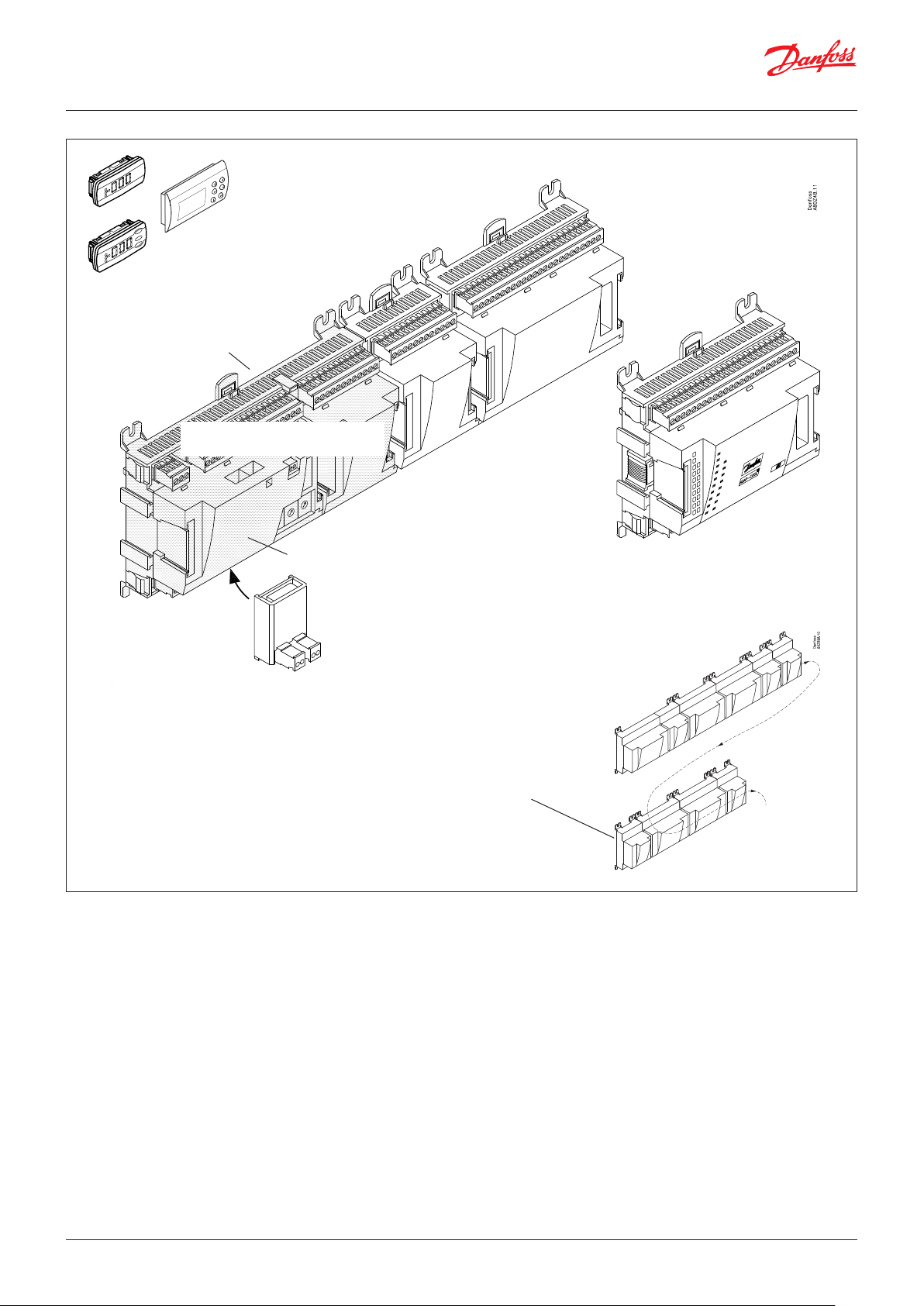
Extension module with
additional analogue inputs
External display for
suction pressure etc.
Bottom part
Controller with analogue inputs
and relay outputs.
Extension module with additional
relay outputs and additional
analogue inputs.
Top part
Extension module with
2x analogue output signals
The module with additional relay outputs is
also available in a version where the top part
is provided with change-over switches so
that the relays can be overridden.
If the row of modules needs to
be interrupted due to length or
external positioning, a communication module should be used.
8 | BC245386497365en-000801 © Danfoss | Climate Solutions | 2022.02
Page 9
User Guide | Pack controller, type AK-PC 782A
1. Controller
Type Function Application
AK-PC 782A
Controller for capacity control of MT (10 compressors), IT (8 compressors) and
LT (4 compressors).
Up to 3 unloaders per compressor, 8 fans and max. 220 inputs/outputs.
Transcritical CO booster control, parallel
compression / Oil management / Heat recovery
/ CO gas pressure
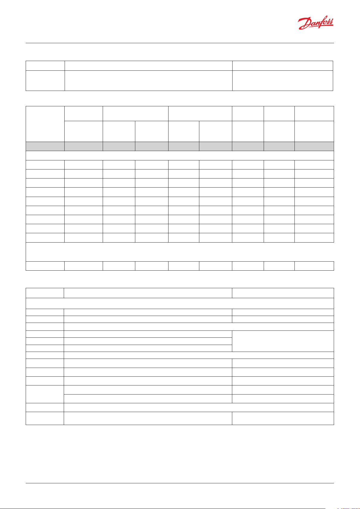
2. Extension modules and survey of inputs and outputs
Type Analogue
inputs
For sensors,
pressure
transmitters etc.
Controller 11 4 4 - - - -
Extension modules
AK-XM 101A 8
AK-XM 102A 8
AK-XM 102B 8
AK-XM 103A 4 4
AK-XM 204A 8
AK-XM 204B 8 x
AK-XM 205A 8 8
AK-XM 205B 8 8 x
AK-XM 208C 8 4
On/Off outputs On/off supply voltage
Relay
(SPDT)
Solid state Low voltage
(DI signal)
(max. 80 V)
High voltage
(max. 260 V)
Analogue
outputs
0 – 10 V DC For valves
Stepper
output
with step
control
Module with
switches
For override of
relay outputs
The following extension module can be placed on the PC board in the controller module.
There is only room for one module.
AK-OB 110 2
3. AK operation and accessories
Type Function Application
Operation
AK-ST 500 Software for operation of AK controllers AK-operation
- Cable between PC and AK controller USB A-B (Standard IT cable)
Accessories Power supply module 230 V / 115 V to 24 V DC
AK-PS 075 18 VA
Supply for controllerAK-PS 150 36 VA
AK-PS 250 60 VA
Accessories External display that can be connected to the controller module. For showing e.g. the suction pressure
EKA 163B Display
EKA 164B Display with operation buttons
MMIGRS2 Graphic display with operation
-
Accessories Communication modules for controllers where modules cannot be connected continuously
AK-CM 102 Communication module
Cable between EKA display and controller Length = 2 m, 6 m
Cable between graphic display and controller Length = 1.5 m, 3.0 m
Data communication for external extension
modules
On the following pages there is data specific to each module.
© Danfoss | Climate Solutions | 2022.02 BC245386497365en-000801 | 9
Page 10
User Guide | Pack controller, type AK-PC 782A
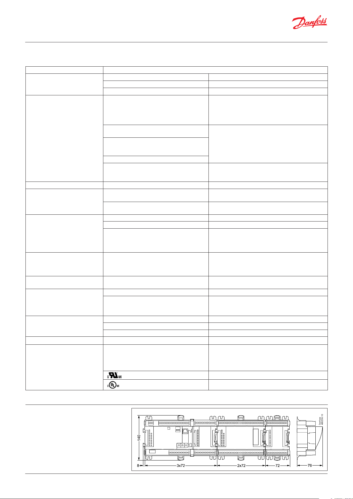
2.2 Common data for modules
Supply voltage 24 V DC/AC ±20%
Power consumption AK-__ (controller) 8 VA
AK-XM 101, 102, 103, 107, AK-CM 102 2 VA
AK-XM 204, 205, 208 5 VA
Analogue inputs Pt 1000 ohm /0 °C Resolution: 0.1 °C
Pressure transmitter type AKS 32R / AKS 2050
MBS 2050 / AKS 32 (1 – 5 V)
Other pressure transmitter:
Ratiometric signal
Min. and Max. pressure must be set
Voltage signal 0 – 10 V
Contact function (On/Off) On at R < 20 ohm
Analogue outputs 0 – 10 V Accuracy +/- 100 mV
On/off supply voltage inputs Low voltage
Relay outputs
SPDT
Solid state outputs Can be used for loads that are cut in and out
Stepper outputs Used for valves with stepper input 20 – 500 step/s
Ambient temperature During transport -40 – 70 °C
Enclosure Material PC / ABS
Weight with screw terminals Modules in 100- / 200- / controller-series Ca. 200 g / 500 g / 600 g
Approvals EU low voltage directive and EMC requirements
The mentioned data applies to all modules.
If data is specific, this is mentioned together with the module in question.
0 / 80 V AC/DC
High voltage
0 / 260 V AC
AC-1 (ohmic) 4 A
AC-15 (inductive) 3 A
U Min. 24 V
frequently,
e.g. Ejector valves, Oil valves, fans and AKV valves
During operation -20 – 55 °C ,
Class IP10, VBG 4
Mounting For mounting on panel wall or DIN rail
are complied with
Dimensions
Accuracy: ±0.5 °C
±0.5 °C between -50 °C and 50 °C
±1 °C between -100 °C and -50 °C
±1 °C between 50 °C and 130 °C
Resolution:1 mV
Accuracy +/- 10 mV
Max. connection of 5 pressure transmitters on one
module
Off at R > 2K ohm
(Gold-plated contacts not necessary)
Off: U < 2 V
On: U > 10 V
Off: U < 24 V
On: U > 80 V
Max. 230 V
Low and high voltage must not be connected to the
same output group
Max. 240 V AC, Min. 48 V AC
Max. 0,5 A,
Leak < 1 mA
Max. 1 AKV
Separate supply to stepper outputs : 24 AC/DC
0 – 95% RH (non condensing)
No shock influences / vibrations
LVD tested according to EN 60730
EMC tested
Immunity according to EN 61000-6-2
Emission according to EN 61000-6-3
E31024 for PC-module
E357029 for XM and CM-modules
The module dimension is 72 mm.
Modules in the 100-series consist of one
module.
Modules in the 200-series consist of two
modules.
Controllers consist of three modules.
The length of an aggregate unit = n x 72 + 8
10 | BC245386497365en-000801 © Danfoss | Climate Solutions | 2022.02
Page 11
User Guide | Pack controller, type AK-PC 782A
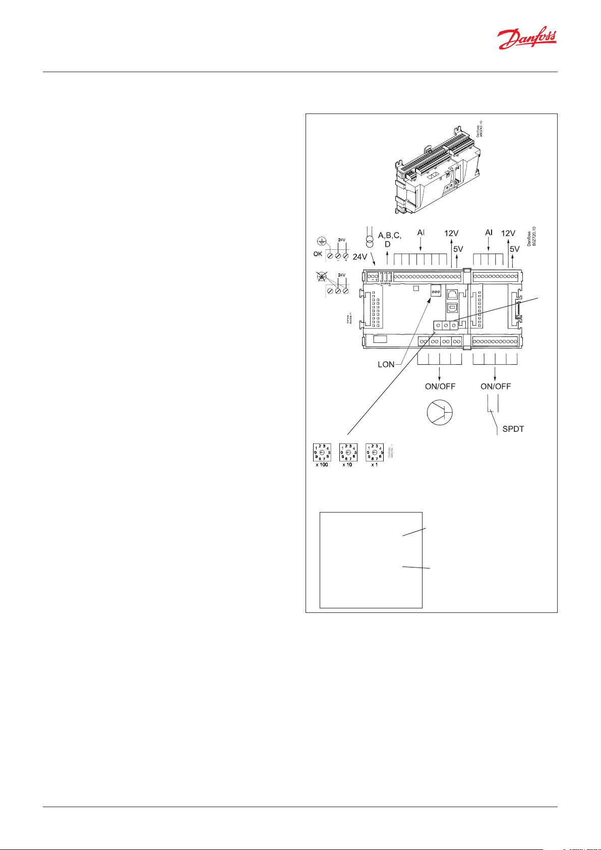
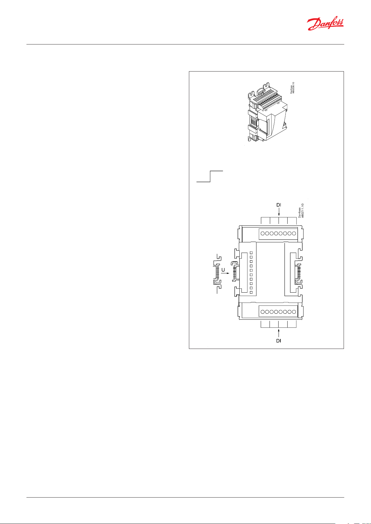
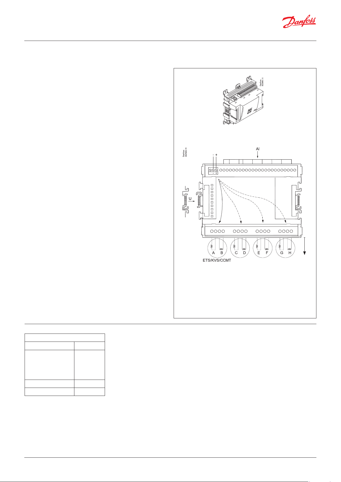
2.3 Controller
Function
There are several controllers in the series. The function is
determined by the programmed software, but on the outside
the controllers are identical – they all have the same connection
possibilities:
11 analogue inputs for sensors, pressure transmitters, voltage
signals and contact signals.
8 digital outputs, with 4 Solid state outputs and 4 relay outputs.
Supply voltage
24 V AC or DC to be connected to the controller.
The 24 V must not be retransmitted and used by other controllers
as it is not galvanically separated from inputs and outputs. In other
words, you must use a transformer for each controller. Class II is
required. The terminals must not be earthed.
The supply voltage to any extension module is transmitted via the
plug on the right-hand side.
The size of the transformer is determined by the power
requirement of the total number of modules.
The supply voltage to a pressure transmitter can be taken either
from the 5 V output or from the 12 V output depending on
transmitter type.
Data communication
If the controller is to be included in a system, communication must
take place via the LON connection.
The installation has to be made as mentioned in the separate
instructions for LON communication.
Address setting
If it is a system manager AK-SM .., then 1-999
Service PIN
When the controller is connected to the data communication
cable, the gateway must have knowledge of the new controller.
This is obtained by pushing the key PIN. The LED “Status” will flash
when the gateway sends an acceptance message.
Operation
The configuration operation of the controller must take place
from the software program “Service Tool”. The program must be
installed on a PC, and the PC must be connected to the controller
via the USB-B plug on the front of the unit.
Light-emitting diodes
There are two rows with LEDs indicating:
Left row:
• Voltage supply to the controller
• Communication active with the bottom PC board (red = error)
• Status of outputs DO1 to DO8
Right row:
• Software status (slow flash = OK)
• Communication with Service Tool
• Communication on LON
• Communication with AK-CM 102
• Alarm when LED flashes
– 1 LED that is not used
• Communication with display on RJ11 plug
• “Service Pin” switch has been activated
PIN
Address
n Power
n Comm
n DO1 n Status
n DO2 n Service Tool
n DO3 n LON
n DO4 n I/O Extension
n DO5 n Alarm
n DO6
n DO7 n Display
n DO8 n Service Pin
Keep the safety distance!
Low and high voltage must
not be connected to the
same output group
Slow flash = OK
Quick flash = answer from gateway
Constantly ON = error
Constantly OFF = error
Flash = active alarm/not cancelled
Constant ON = Active alarm/cancelled
A small module (option board) can be placed on the bottom part
of the controller. The module is described later in the document.
© Danfoss | Climate Solutions | 2022.02 BC245386497365en-000801 | 11
Page 12
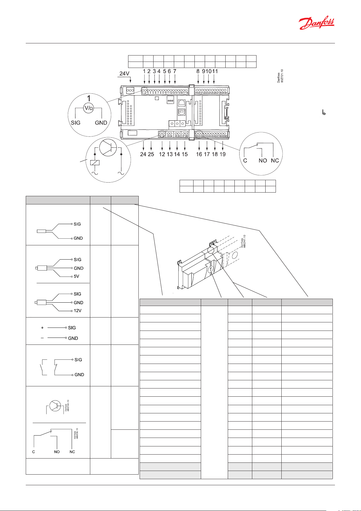
User Guide | Pack controller, type AK-PC 782A
Point
Analogue
inputs
on 1 - 11
Solid state outputs
on 12 - 15
Relay or AKV coil
fx 230 V AC
S
Pt 1000 ohm/0°C
P
AKS 32R
AKS 32
U
On/Off Ext.
DO
Option Board
3: Brown
2: Blue
1: Black
3: Brown
2: Black
1: Red
AKV
Signal
Signal type
S1
S2
Saux_
SsA
Pt 1000
SdA
Shr
Stw
Sgc
P0A
P0B
PcA
PcB
Paux
Pgc
Prec
AKS 32R /
AKS 2050
MBS 8250
-1 - xx bar
AKS 32
-1 - zz bar
0 - 5 V
...
Main
switch
Day/
Night
Door
0 - 10 V
Active at:
Closed
/
Open
Level
switch
Active at:
AKV
Comp 1
Comp 2
Fan 1
Alarm
Light
Rail heat
Defrost
Solenoid
valve
Please see the signal
on the page with the
module.
On
/
Off
Point 1 2 3 4 5 6 7 8 9 10 11
Type AI1 AI2 AI3 AI4 AI5 AI6 AI7 AI8 AI9 AI10 AI11
24 and 25 used only
when "Option board
fitted"
Point 12 13 14 15 16 17 18 19
Type DO1 DO2 DO3 DO4 DO5 DO6 DO7 DO8
Signal Module Point Terminal Signal type /Active at
1 (AI 1) 1 - 2
2 (AI 2) 3 - 4
3 (AI 3) 5 - 6
4 (AI 4) 7 - 8
5 (AI 5) 9 - 10
6 (AI 6) 11 - 12
7 (AI 7) 13 - 14
8 (AI 8) 19 - 20
9 (AI 9) 21 - 22
10 (AI 10) 23 - 24
11 (AI 11) 25 - 26
1
12 (DO 1) 31 - 32
13 (DO 2) 33 - 34
14 (DO 3) 35 - 36
15 (DO 4) 37 - 38
16 (DO 5) 39 - 40- 41
17 (DO6) 42 - 43 - 44
18 (DO7) 45 - 46 - 47
19 (DO8) 48 - 49 - 50
24 -
25 -
Terminal 15 & 27:
12 V max. 100 mA in total.
Terminal 16 & 28:
5 V max. 100 mA in total.
Terminal
17, 18, 29, 30:
(Cable screen)
The screen on the
pressure transmitter
cables must only be
connected at the end of
the controller.
Relay outputs on
16 - 19
12 | BC245386497365en-000801 © Danfoss | Climate Solutions | 2022.02
Page 13
User Guide | Pack controller, type AK-PC 782A
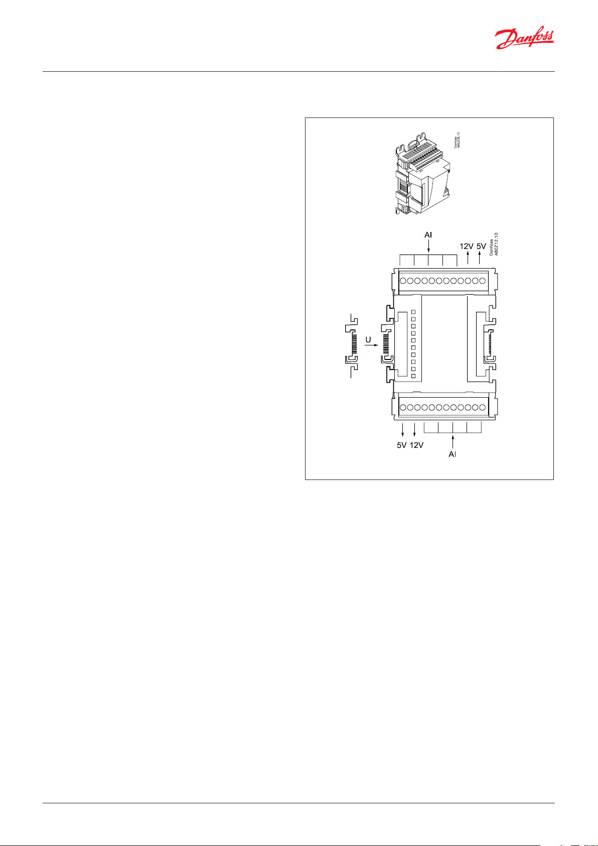
2.3.1 Extension module AK-XM 101A
Function
The module contains 8 analogue inputs for sensors, pressure
transmitters, voltage signals and contact signals.
Supply voltage
The supply voltage to the module comes from the previous
module in the row.
Supply voltage to a pressure transmitter can be taken from either
the 5 V output or the 12 V output depending on transmitter type.
Light-emitting diodes
Only the two top LEDs are used. They indicate the following:
• Voltage supply to the module
• Communication with the controller is active (red = error)
© Danfoss | Climate Solutions | 2022.02 BC245386497365en-000801 | 13
Page 14
User Guide | Pack controller, type AK-PC 782A
Point
S
Pt 1000 ohm/0°C
P
AKS 32R
AKS 32
At the top, the
signal input is
the left of the
two terminals.
At the bottom,
the signal input
is the right of the
two terminals.
3: Brown
2: Blue
1: Black
3: Brown
2: Black
1: Red
Signal Signal
type
S1
S2
Saux
SsA
Pt 1000
SdA
Shr
Stw
Sgc
P0A
P0B
PcA
PcB
AKS 32R /
AKS 2050
MBS 8250
-1 - xx bar
Paux
Pgc
Prec
AKS 32
-1 - zz bar
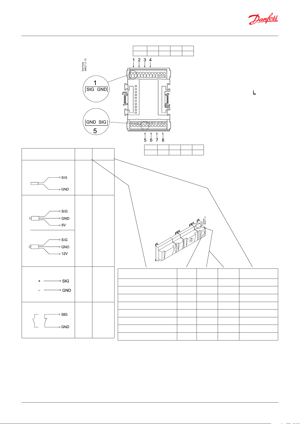
Point 1 2 3 4
Type AI1 AI2 AI3 AI4
Point 5 6 7 8
Type AI5 AI6 AI7 AI8
Terminal 9 & 15:
12 V max. 100 mA in total.
Terminal 10 & 16:
5 V max. 100 mA in total.
Terminal
11, 12, 13, 14:
(Cable screen)
The screen on the pressure
transmitter cables must
only be connected at the
end of the controller.
U
...
0 - 5 V
0 - 10 V
Signal Module Point
1 (AI 1) 1 - 2
Terminal
Signal type /
Active at
2 (AI 2) 3 - 4
3 (AI 3) 5 - 6
On/Off
Ext.
Main
switch
Day/
Night
Door
Level
switch
Active at:
Closed
/
Open
4 (AI 4) 7 - 8
5 (AI 5) 17 - 18
6 (AI 6) 19 - 20
7 (AI 7) 21 - 22
8 (AI 8) 23 - 24
14 | BC245386497365en-000801 © Danfoss | Climate Solutions | 2022.02
Page 15
User Guide | Pack controller, type AK-PC 782A
2.3.2 Extension module AK-XM 102A / AK-XM 102B
Function
The module contains 8 inputs for on/off voltage signals.
Signal
AK-XM 102A is for low voltage signals.
AK-XM 102B is for high voltage signals.
Supply voltage
The supply voltage to the module comes from the previous
module in the row.
Light-emitting diodes
They indicate:
• Voltage supply to the module
• Communication with the controller is active (red = error)
• Status of the individual inputs 1 to 8 (when lit = voltage
AK-XM 102A
Max. 24 V
On/Off:
On: DI > 10 V AC/DC
Off: DI < 2 V AC/DC
AK-XM 102B
Max. 230 V
On/Off:
On: DI > 80 V AC
Off: DI < 24 V AC
© Danfoss | Climate Solutions | 2022.02 BC245386497365en-000801 | 15
Page 16
User Guide | Pack controller, type AK-PC 782A
Point
Signal Active at
DI Ext.
AK-XM 102A: Max. 24 V
AK-XM 102B: Max. 230 V
(The module can not register a pulse signal from e.g. a
reset function.)
Main
switch
Day/
Night
Comp.
safety 1
Comp.
safety 2
Level
switch
Closed
(voltage on)
/
Open
(voltage
off)
Point 1 2 3 4
Type DI1 DI2 DI3 DI4
Point 5 6 7 8
Type DI5 DI6 DI7 DI8
Signal Module Point Terminal Active at
1 (DI 1) 1 - 2
2 (DI 2) 3 - 4
3 (DI 3) 5 - 6
4 (DI 4) 7 - 8
5 (DI 5) 9 - 10
6 (DI 6) 11 - 12
7 (DI 7) 13 - 14
8 (DI 8) 15 - 16
16 | BC245386497365en-000801 © Danfoss | Climate Solutions | 2022.02
Page 17
User Guide | Pack controller, type AK-PC 782A
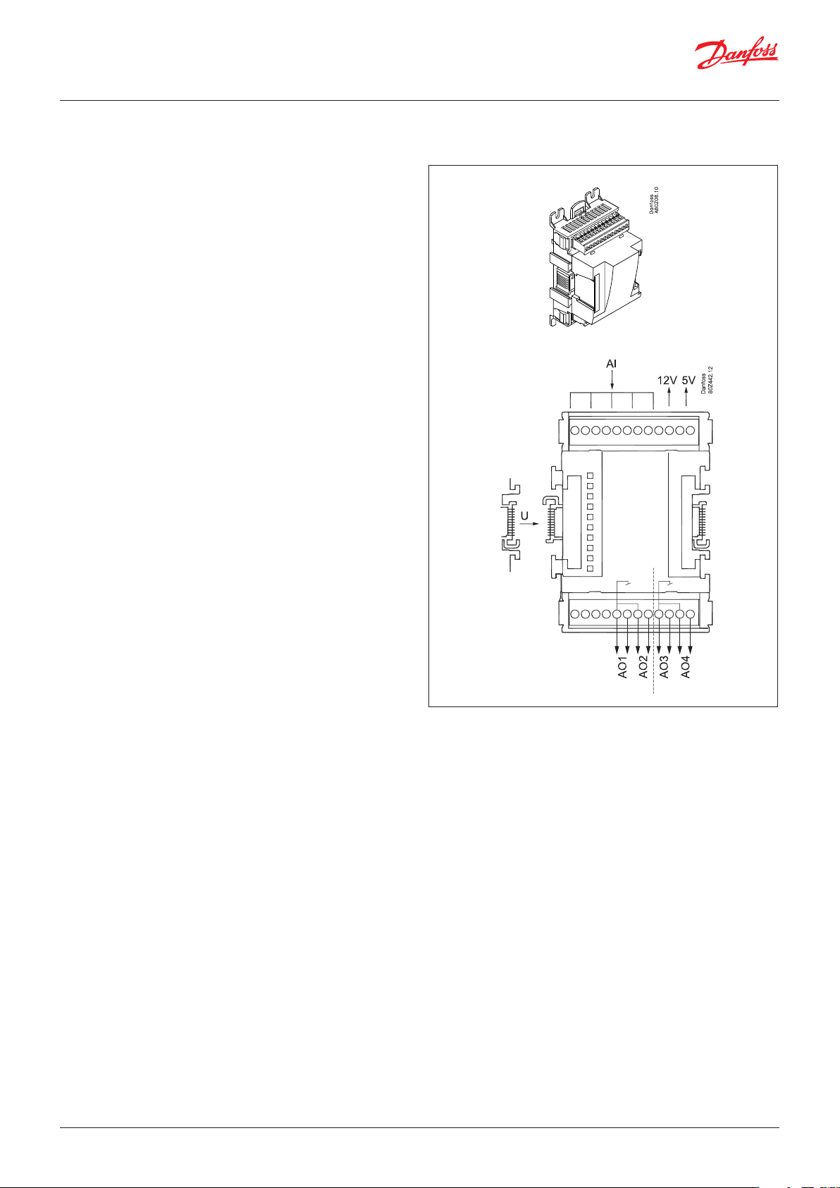
2.3.3 Extension module AK-XM 103A
Function
The module contains :
4 analogue inputs for sensors, pressure transmitters, voltage
signals and contact signals.
4 analogue voltage outputs of 0 - 10 V
Supply voltage
The supply voltage to the module comes from the previous
module in the row.
Supply voltage to a pressure transmitter can be taken from either
the 5 V output or the 12 V output depending on transmitter type.
Galvanic isolation
The inputs are galvanically separated from the outlets.
The outlets AO1 and AO2 are galvanically separated from AO3 and
AO4.
Light-emitting diodes
Only the two top LEDs are used. They indicate the following:
• Voltage supply to the module
• Communication with the controller is active (red = error)
Max. load
I < 2.5 mA
R > 4 kΩ
Accuracy
Analog inputs: +/- 10 mV
Analog outputs: +/- 100 mV
© Danfoss | Climate Solutions | 2022.02 BC245386497365en-000801 | 17
Page 18
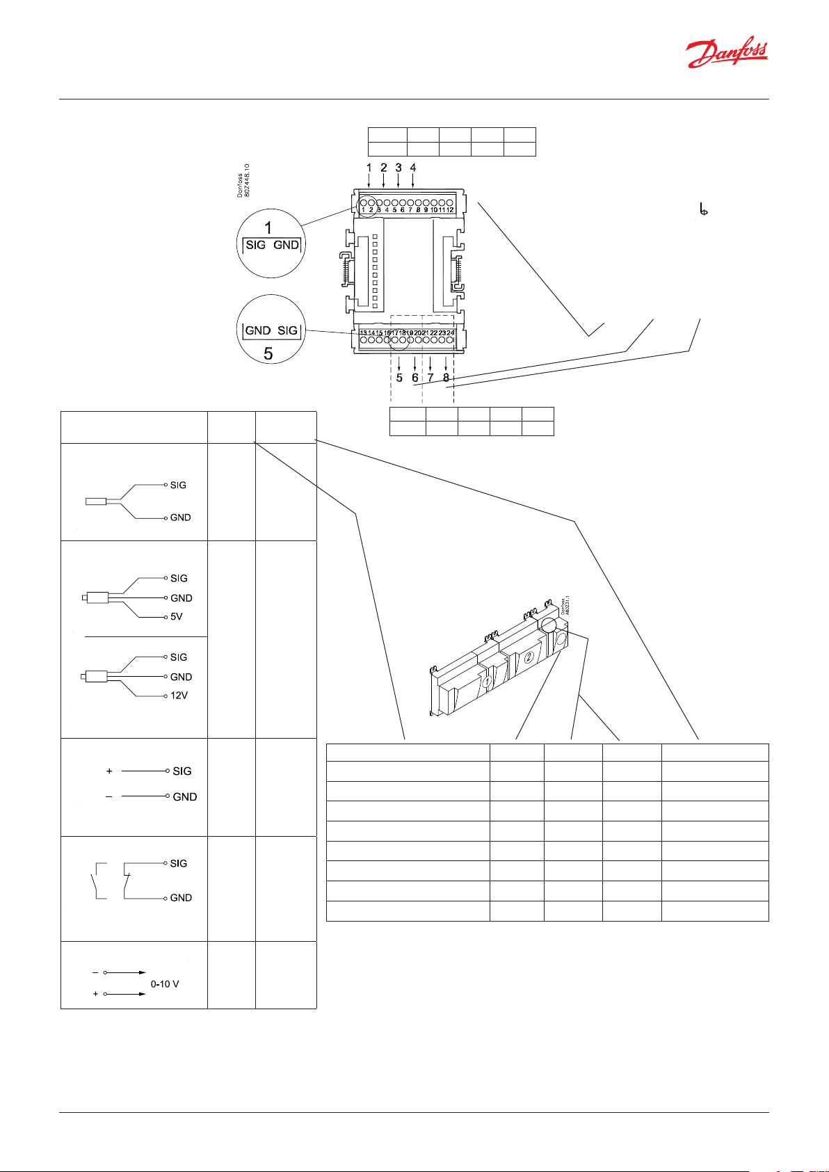
User Guide | Pack controller, type AK-PC 782A
Point
S
Pt 1000 ohm/0°C
P
AKS 32R
AKS 32
At the top, the
signal input is
the left of the
two terminals.
At the bottom,
the signal input
is the right of the
two terminals.
3: Brown
2: Blue
1: Black
3: Brown
2: Black
1: Red
Signal Signal
type
S1
S2
Saux
SsA
Pt 1000
SdA
Shr
Stw
Sgc
P0A
P0B
PcA
PcB
Paux
Pgc
Prec
AKS 32R /
AKS 2050
MBS 8250
-1 - xx bar
AKS 32
-1 - zz bar
Point 1 2 3 4
Type AI1 AI2 AI3 AI4
Point 5 6 7 8
Type AO1 AO 2 AO3 AO4
Terminal 9:
12 V max. 100 mA in total.
Terminal 10:
5 V max. 100 mA in total.
Terminal 11, 12:
(Cable screen)
The screen on the pressure
transmitter cables must only
be connected at the end of the
controller.
Galvanic isolation:
AI 1-4 ≠ AO 1-2 ≠ AO 3-4
U
...
0 - 5 V
0 - 10 V
Signal Module Point Terminal Signal type /Active at
1 (AI 1) 1 - 2
2 (AI 2) 3 - 4
3 (AI 3) 5 - 6
4 (AI 4) 7 - 8
On/Off Ext.
Main
switch
Day/
Night
Door
Active at:
Closed
/
Open
5 (AO 1) 17 - 18
6 (AO 2) 19 - 20
7 (AO 3) 21 - 22
8 (AO 4) 23 - 24
Level
switch
AO
0 – 10 V
18 | BC245386497365en-000801 © Danfoss | Climate Solutions | 2022.02
Page 19
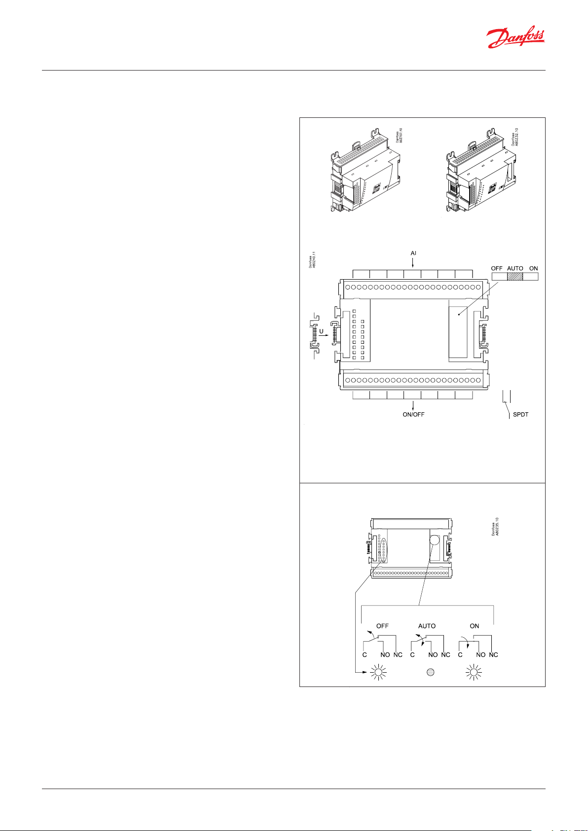
User Guide | Pack controller, type AK-PC 782A
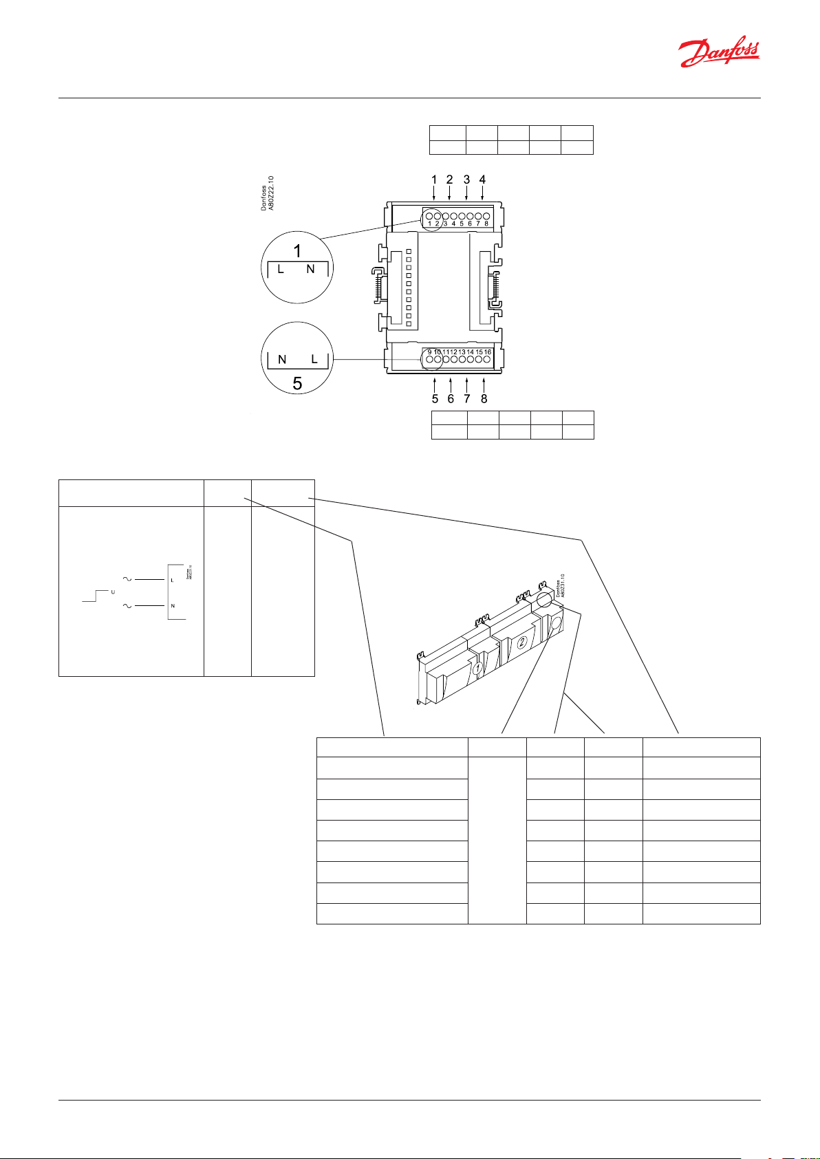
2.3.4 Extension module AK-XM 204A / AK-XM 204B
Function
The module contains 8 relay outputs.
Supply voltage
The supply voltage to the module comes from the previous
module in the row.
AK-XM 204B only
Override of relay
Eight change-over switches at the front make it possible to
override the relay’s function.
Either to position OFF or ON.
In position Auto the controller carries out the control.
Light-emitting diodes
There are two rows with LEDs. They indicate the following:
Left row:
• Voltage supply to the controller
• Communication active with the bottom PC board (red = error)
• Status of outputs DO1 to DO8
Right row: (AK-XM 204B only):
• Override of relays
ON = override
OFF = no override
AK-XM 204A AK-XM 204B
Fuses
Behind the upper part there is a fuse for each output.
Max. 230 V
AC-1: max. 4 A (ohmic)
AC-15: max. 3 A (Inductive)
AK-XM 204B
Override of relay
Keep the safety distance!
Low and high voltage must
not be connected to the
same output group
© Danfoss | Climate Solutions | 2022.02 BC245386497365en-000801 | 19
Page 20
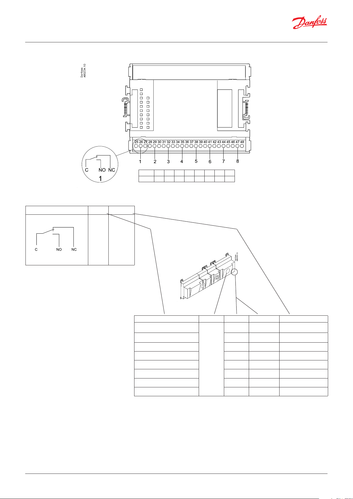
User Guide | Pack controller, type AK-PC 782A
Point
Signal Active at
DO
Comp. 1
Comp. 2
Fan 1
Alarm
Solenoid
valve
On
/
Off
Point 1 2 3 4 5 6 7 8
Type DO1 DO2 DO3 DO4 DO5 DO6 DO7 DO8
Signal Module Point Terminal Active at
1 (DO 1) 25 - 27
2 (DO 2) 28 - 30
3 (DO 3) 31 - 33
4 (DO 4) 34 -36
5 (DO 5) 37 - 39
6 (DO 6) 40 - 41 - 42
7 (DO 7) 43 - 44 - 45
8 (DO 8) 46 - 47 - 48
20 | BC245386497365en-000801 © Danfoss | Climate Solutions | 2022.02
Page 21
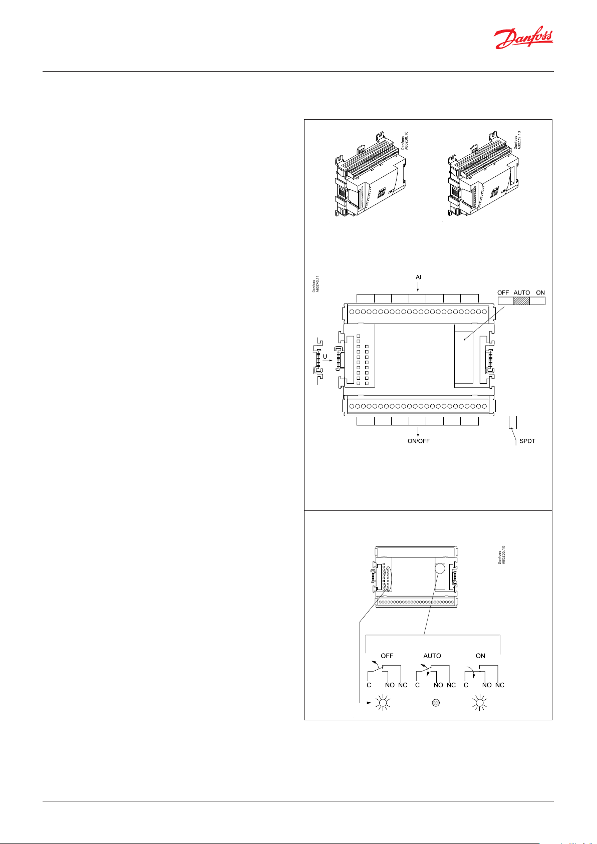
User Guide | Pack controller, type AK-PC 782A
2.3.5 Extension module AK-XM 205A / AK-XM 205B
Function
The module contains:
8 analogue inputs for sensors, pressure transmitters, voltage
signals and contact signals.
8 relay outputs.
Supply voltage
The supply voltage to the module comes from the previous
module in the row.
AK-XM 205B only
Override of relay
Eight change-over switches at the front make it possible to
override the relay’s function.
Either to position OFF or ON.
In position Auto the controller carries out the control.
Light-emitting diodes
There are two rows with LEDs. They indicate the following:
Left row:
• Voltage supply to the controller
• Communication active with the bottom PC board (red = error)
• Status of outputs DO1 to DO8
Right row: (AK-XM 205B only):
• Override of relays
– ON = override
– OFF = no override
Fuses
Behind the upper part there is a fuse for each output.
AK-XM 205A AK-XM 205B
max. 10 V
Max. 230 V
AC-1: max. 4 A (ohmic)
AC-15: max. 3 A (Inductive)
Keep the safety distance!
Low and high voltage
must not be connected to
the same output group
AK-XM 205B
Override of relay
© Danfoss | Climate Solutions | 2022.02 BC245386497365en-000801 | 21
Page 22
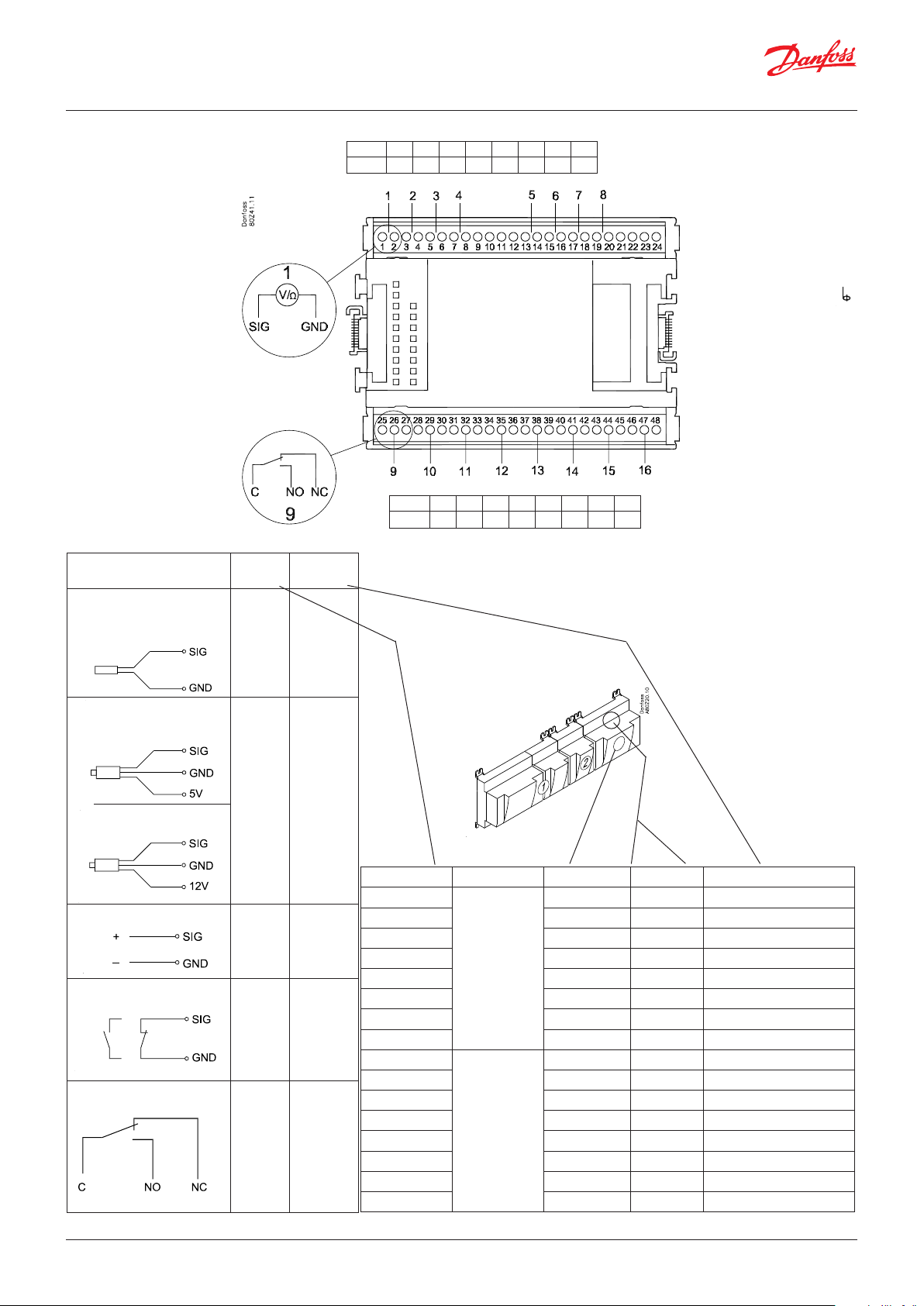
User Guide | Pack controller, type AK-PC 782A
Point
S
Pt 1000 ohm/0°C
P
AKS 32R
AKS 32
U
On/Off
DO
3: Brown
2: Blue
1: Black
3: Brown
2: Black
1: Red
Signal Signal
type
S1
S2
Saux
SsA
Pt 1000
SdA
Shr
Stw
Sgc
P0A
P0B
PcA
PcB
Paux
Pgc
Prec
...
AKS 32R /
AKS 2050
MBS 8250
-1 - xx bar
AKS 32
-1 - zz bar
0 - 5 V
0 - 10 V
Ext. Main
switch
Active at:
Day/
Night
Closed
Door
Level
Open
switch
Comp 1
Comp 2
Fan 1
Active at:
Alarm
Light
on
Rail heat
Defrost
Off
Solenoid
valve
Point 1 2 3 4 5 6 7 8
Type AI1 AI2 AI3 AI4 AI5 AI6 AI7 AI8
Point 9 10 11 12 13 14 15 16
Type DO1 DO2 DO3 DO4 DO5 DO6 DO7 DO8
Signal Module Point Terminal Signal type /Active at
/
/
Terminal 9 & 21:
12 V max. 100 mA in total.
Terminal 10 & 22:
5 V max. 100 mA in total.
Terminal 11, 12, 23, 24 :
(Cable screen)
The screen on the pressure
transmitter cables must only
be connected at the end of
the controller.
1 (AI 1) 1 - 2
2 (AI 2) 3 - 4
3 (AI 3) 5 - 6
4 (AI 4) 7 - 8
5 (AI 5) 13 - 14
6 (AI 6) 15 - 16
7 (AI 7) 17 - 18
8 (AI 8) 19 -20
9 (DO 1) 25 - 26 - 27
10 (DO 2) 28 - 29 - 30
11 (DO 3) 31 - 30 - 33
12 (DO 4) 34 - 35 - 36
13 (DO 5) 37 - 38 - 39
14 (DO6) 40 - 41 - 42
15 (DO7) 43 - 44 - 45
16 (DO8) 46 - 47 - 48
22 | BC245386497365en-000801 © Danfoss | Climate Solutions | 2022.02
Page 23
User Guide | Pack controller, type AK-PC 782A
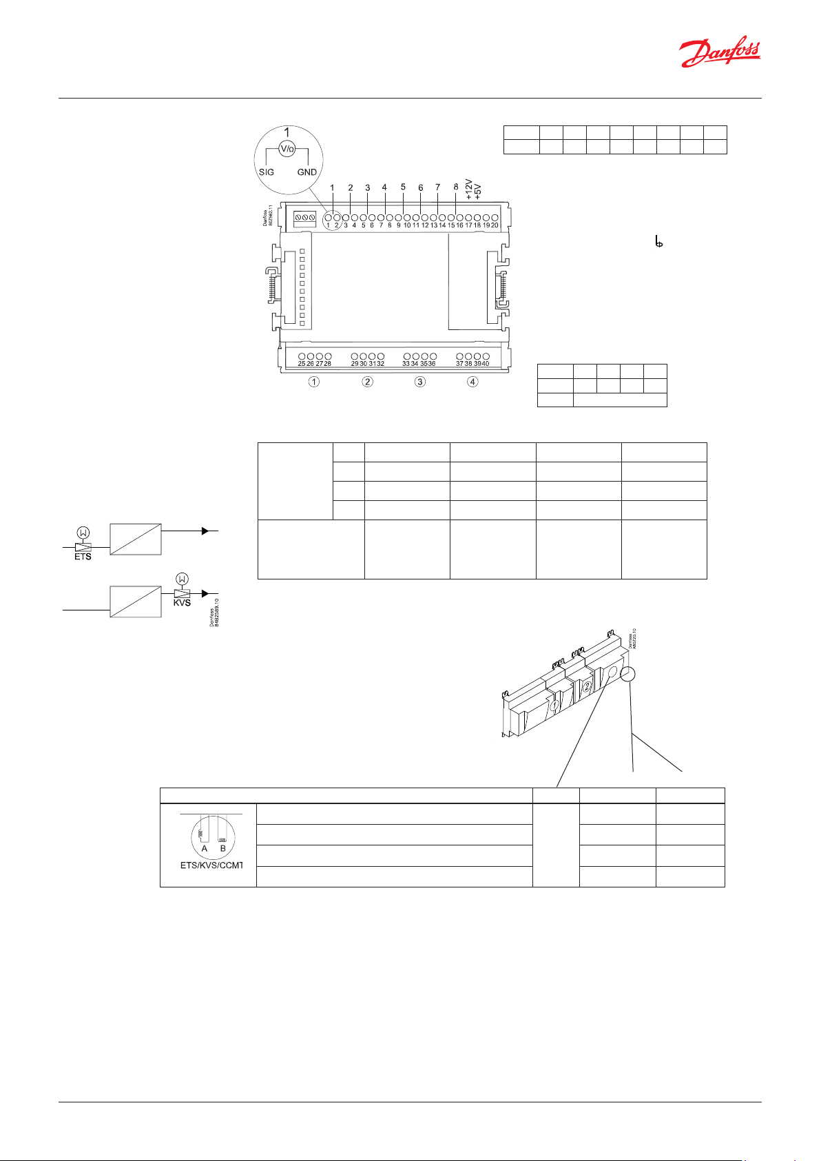
2.3.6 Extension module AK-XM 208C
Function
The module contains:
8 analogue inputs for sensors, pressure transmitters, voltage
signals and contact signals.
4 outputs for stepper motors.
Supply voltage
The supply voltage to the module comes from the previous
module in the row. Here supplied with 5 VA.
An additional and separated power supply must be installed,
which must be galvanically separated from the supply for the
control range. Class II is required.
(Power requirements: 7.8 VA for controller + xx VA per valve).
2 separated UPS´s are recommended, one for the pack controller
and another AK-XM 208C module if the valves need to open/ close
during a power failure. If the AK-CM 102 module is installed it is
also recommended a separated UPS.
Light-emitting diodes
There is one row with LEDs, indicating the following:
• Voltage supply to the module
• Communication active with the bottom PC board (red = error)
• Step1 to step4 OPEN: Green = Open
• Step1 to step4 CLOSE: Green = Close
• Red flash = Error on motor or connection
Separate voltage supply
is required
24 V AC/DC / fx. 13 VA
Output:
24 V DC
20-500 step/s
Max. Phase current = 325 mA RMS
∑ P
= 21 VA
max.
The connection to the valve must
not be broken using a relay
max. 10 V
L = max. 30 m
Valve data
Type P
ETS 12.5 - ETS 400
KVS 15 - KVS 42
CCMT 2 - CCMT 8
CCM 10 - CCM 40
CTR 20
CCMT 16 - CCMT 42 5.1 VA
CCMT - 3L/5L/8L 4.0 VA
1.3 VA
Power supply to AK-XM 208C:
Fx: 7.8 + (4 x 1.3) = 13 VA AK-PS 075
Fx: 7.8 + (4 x 5.1) = 28,2 VA AK-PS 150
© Danfoss | Climate Solutions | 2022.02 BC245386497365en-000801 | 23
Page 24
User Guide | Pack controller, type AK-PC 782A
Point
CCMT
Step /
Terminal
ETS
CCM / CCMT
CTR
KVS
Point 1 2 3 4 5 6 7 8
Type AI1 AI2 AI3 AI4 AI5 AI6 AI7 AI8
Terminal 17: 12 V max. 100 mA in total.
Terminal 18: 5 V max. 100 mA in total.
Terminal 19, 20:
(Cable screen)
Point 9 10 11 12
Step 1 2 3 4
Type AO
1 25 26 27 28
2 29 30 31 32
3 33 34 35 36
4 37 38 39 40
White Black Red Green
Valve Module Step Terminal
1 (point 9) 25 - 28
2 (point 10) 29 - 32
3 (point 11) 33 - 36
4 (point 12) 37 - 40
24 | BC245386497365en-000801 © Danfoss | Climate Solutions | 2022.02
Page 25
User Guide | Pack controller, type AK-PC 782A
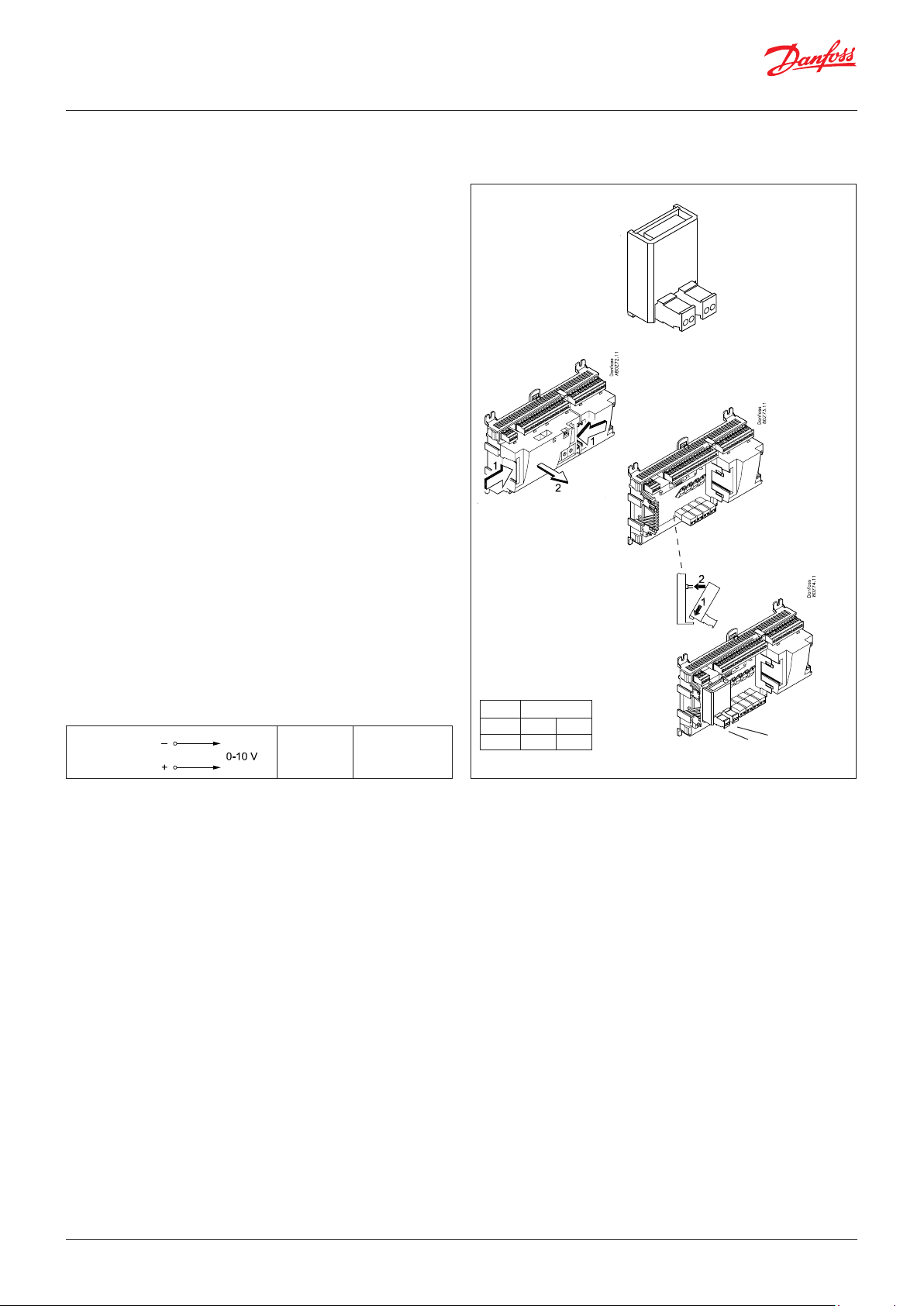
2.3.7 Extension module AK-OB 110
Function
The module contains two analogue voltage outputs of 0 – 10 V.
Supply voltage
The supply voltage to the module comes from the controller
module.
Placing
The module is placed on the PC board in the controller module.
Point
The two outputs have points 24 and 25. They are shown on the
earlier page where the controller is also mentioned.
Max. load
I < 2.5 mA
R > 4 kohm
Accuracy
Analog outputs: +/- 100 mV
AO
AO 0 - 10 V
Module
Point 24 25
Type AO1 AO 2
1
AO2
AO1
© Danfoss | Climate Solutions | 2022.02 BC245386497365en-000801 | 25
Page 26
User Guide | Pack controller, type AK-PC 782A
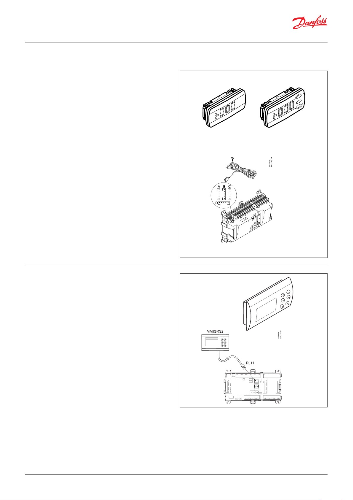
2.3.8 Extension module EKA 163B / EKA 164B
Function
Display of important measurements from the controller, e.g.
appliance temperature, suction pressure or condensing pressure.
Setting of the individual functions can be performed by using the
display with control buttons.
It is the controller used that determines the measurements and
settings that can occur.
Connection
The extension module is connected to the controller module via
a cable with plug connections. You have to use one cable per
module. The cable is supplied in various lengths.
Both types of display (with or without control buttons) can be
connected to either display output A, B, C and D.
Ex.
A: P0. Suction pressure in °C.
B: Pc. Condensing pressure in °C.
When the controller starts up, the display will show the output
that is connected.
- - 1 = output A
- - 2 = output B
etc.
EKA 163B EKA 164B
Placing
The extension module can be placed at a distance of up to 15 m
from the controller module.
Point
No point has to be defined for a display module – you simply
connect it.
2.3.9 Graphic display MMIGRS2
Function
Setting and display of values in the controller.
Connection
The display connects to the controller via a cable with RJ11 plug
connections.
Supply voltage
Received from the controller via cable and RJ11 connector.
Do not connect a seperate power supply for this display.
Termination
The display must be terminated. Mount a connection between the
terminals H and R.
(AK-PC 782A is terminated internally.)
Placing
The display can be placed at a distance of up to 3 m from the
controller.
Point / Address
No point has to be defined for a display – you simply connect it.
However, the address must be verified. See the instructions
accompanying the controller.
26 | BC245386497365en-000801 © Danfoss | Climate Solutions | 2022.02
To create access, the display must be connected and the address
of MMIGRS2 must be activated.
Setting:
1. Press both the "x-button" and "enter button" and hold for 5
seconds. Subsequently the Bios menu is shown.
2. Select the line "MCX selection", press "enter"
3. Select the line "Man selection", press "enter"
4. The address is shown now. Please check that it is 001, press
"enter". Then data is downloaded from the controller.
Page 27
User Guide | Pack controller, type AK-PC 782A
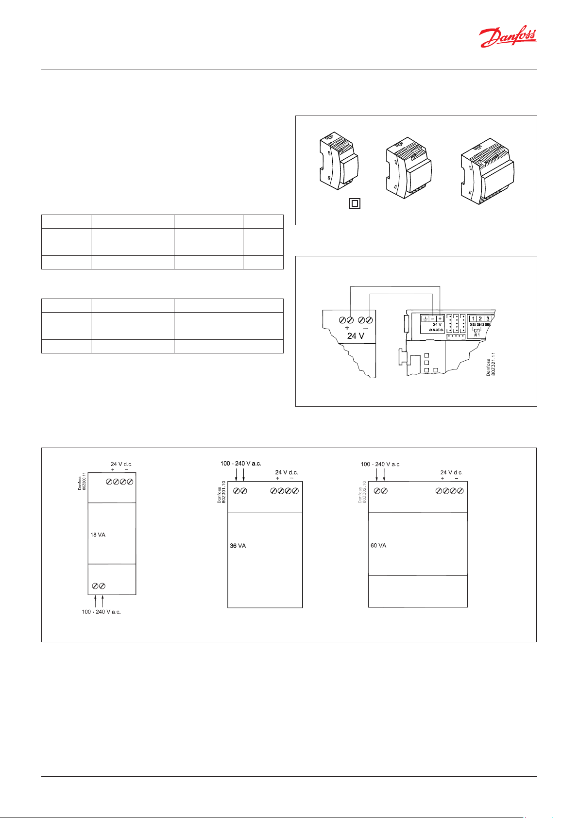
2.3.10 Power supply module AK-PS 075 / 150 / 250
Function
24 V supply for controller.
Supply voltage
230 V AC or 115 V AC (from 100 V AC to 240 V AC)
Placing
On DIN-rail
Effect
Type Output tension Output current Power
AK-PS 075 24 V DC 0.75 A 18 VA
AK-PS 150 24 V DC (adjustable) 1.5 A 36 VA
AK-PS 250 24 V DC (adjustable) 2.5 A 60 VA
Dimension
Type High Width
AK-PS 075 90 mm 36 mm
AK-PS 150 90 mm 54 mm
AK-PS 250 90 mm 72 mm
Class II
Supply to a controller
Connections
AK-PS 075
AK-PS 150
AK-PS 250
© Danfoss | Climate Solutions | 2022.02 BC245386497365en-000801 | 27
Page 28
User Guide | Pack controller, type AK-PC 782A
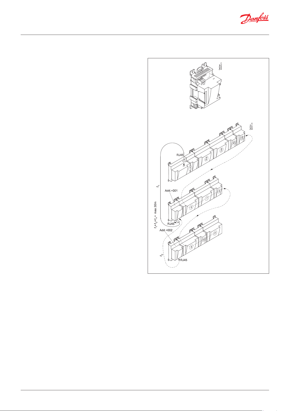
2.3.11 Communication module AK-CM 102
Function
The module is a new communication module, meaning the row of
extension modules can be interrupted.
The module communicates with the regulator via data
communication and forwards information between the controller
and the connected extension modules.
Connection
Communication module and controller fitted with RJ 45 plug
connectors.
Nothing else should be connected to this data communication; a
maximum of 5 communication modules can be connected to one
controller.
Communication cable
One metre of the following is enclosed:
ANSI/TIA 568 B/C CAT5 UTP cable w/ RJ45 connectors.
Positioning
Max. 30 m from the controller
(The total length of the communication cables is 30 m)
Supply voltage
24 volt AC or DC should be connected to the communication
module.
The 24 V can be sourced from the same supply that supplies
the controller. (The supply for the communication module is
galvanically separated from the connected extension modules).
The terminals must not be earthed.
The power consumption is determined by the power consumption
of the total number of modules.
The controller strand load must not exceed 32 VA.
Each AK-CM 102 strand load must not exceed 20 VA.
Max. 32 VA
Max. 20 VA
Max. 20 VA
Point
Connection points on the I/O modules should be defined as if the
modules were an extension of each other.
Address
The address for the first communication module should be set
to 1. Any second module should be set to 2. A maximum of 5
modules can be addressed.
Termination
The termination switch on the final communication module
should be set to ON.
The controller should permanently be set to = ON.
Warning!
Additional modules may only be installed following the
installation of the final module. (Here following module no. 11;
see the sketch.)
After configuration, the address must not be changed.
28 | BC245386497365en-000801 © Danfoss | Climate Solutions | 2022.02
Page 29

User Guide | Pack controller, type AK-PC 782A
2.4 Preface to design
Be aware of the following when the number of extension modules
is being planned. A signal may have to be changed, so that an
additional module may be avoided.
• An ON/OFF signal can be received in two ways. Either as a
contact signal on an analogue input or as voltage on a low or
high-voltage module.
• An ON/OFF output signal can be given in two ways. Either with
a relay switch or with solid state. The primary difference is the
permitted load and that the relay switch contains a cut-out
switch.
Functions
Clock function
Clock function and change-over between summer time and
winter time are contained in the controller.
The clock setting is maintained for at least 12 hours at a power
failure.
The clock setting is kept updated if the controller is linked up in a
network with a system manager.
Start/stop of regulation
Regulation can be started and stopped via the software. External
start/stop can also be connected.
Warning!
The function stops all regulation, including any high-pressure
regulation.
Excess pressure can lead to a loss of charge.
Mentioned below are a number of functions and connections
that may have to be considered when a regulation has to be
planned. There are more functions in the controller than the ones
mentioned here, but those mentioned have been included in
order for the need for connections to be established.
I'm alive function
A relay can be reserved which is pulled during normal regulation.
The relay will be released if the regulation stops with the main
switch or if the controller fails.
Extra temperature sensors and pressure sensors
If additional measurements have to be carried out beyond the
regulation, sensors can be connected to the analogue inputs.
Forced control
The software contains a forced control option. If an extension
module with relay outputs is used, the module’s top part can
be with change-over switches – switches that can override the
individual relays into either OFF or ON position.
Wiring should be done with a safety relay. See Regulating
functions.
Start/stop of compressors
External start/stop can be connected.
Alarm function
If the alarm is to be sent to a signal transmitter, a relay output will
have to be used.
Data communication
The controller module has terminals for LON data communication.
The requirements to the installation are described in a separate
document.
© Danfoss | Climate Solutions | 2022.02 BC245386497365en-000801 | 29
Page 30
User Guide | Pack controller, type AK-PC 782A
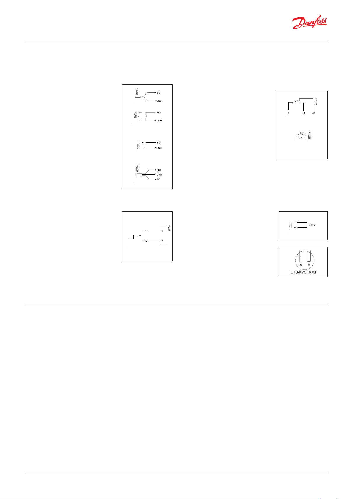
Connections
In principle there are the following types of connections:
Analogue inputs ”AI”
This signal must be connected to two
terminals.
Signals can be received from the following
sources:
• Temperature signal from Pt 1000 ohm
temperature sensor
• Pulse signal or reset signal
• Contact signal where the input is shortcircuited or ”opened”, respectively
• Voltage signal from 0 to 10 V
• Signal from pressure transmitter AKS 32,
AKS 32R, AKS 2050 or MBS 8250.
• The supply voltage is supplied from the
module’s terminal board where there
is both a 5 V supply and a 12 V supply.
When programming, the pressure
transmitter’s pressure range must be set.
ON/OFF voltage inputs ”DI”
This signal must be connected to two
terminals.
• The signal must have two levels, either
0 V or ”voltage” on the input. There are
two different extension modules for this
signal type:
– low-voltage signals, e.g. 24 V
– high-voltage signals, e.g. 230 V
When programming, the function must be set:
• Active when the input is without voltage
• Active when voltage is applied to the input.
ON/OFF output signals ”DO”
There are two types, as follows:
• Relay outputs
All relay outputs are with change-over
relay so that the required function can be
obtained when the controller is without
voltage.
• Solid state outputs
Reserved for ejector valves, oil valves
and AKV valves, but output can cut an
external relay in and out, as with a relay
output.
The output is only found on the
controller module.
When programming, the function must be set:
• Active when the output is activated
• Active when the output is not activated.
Analogue output signal ”AO”
This signal is to be used if a control signal is
to be transmitted to an external unit, e.g. a
frequency converter.
When programming, the signal range must
be defined: 0-5 V, 1-5 V, 0-10 V or 2-10 V.
Pulse signal for the stepper motors.
This signal is used by valve motors of the
type ETS, KVS, CCM and CCMT.
The valve type should be set during
programming.
Limitations
As the system is very flexible regarding the number of connected
units, you must check whether your selection complies with the
few limitations there are.
The complexity of the controller is determined by the software,
the size of the processor, and the size of the memory. It provides
the controller with a certain number of connections from which
data can be downloaded, and others where coupling with relays
can be performed.
The sum of connections cannot exceed 220 (AK-PC 782A).
The number of extension modules must be limited so that
the total power in a row will not exceed 32 VA (including
controller). If the AK-CM 102 communication module is used,
each row of AK-CM 102 must not exceed 20 VA (incl. AK-CM
102). There must not be more than a total of 18 modules
(controller + 17 modules).
No more than 5 pressure transmitters may be connected to one
controller module.
No more than 5 pressure transmitters may be connected to one
extension module.
30 | BC245386497365en-000801 © Danfoss | Climate Solutions | 2022.02
Common pressure transmitter
If several controllers receive a signal from the same pressure
transmitter, the supply to the affected controllers must be wired so
that it is not possible to switch off one of the controllers without
also switching off the others. (If one controller is switched off, the
signal will be pulled down, and all the other controllers will receive
a signal which is too low).
Ejector valves
If ejector valves are used, the smallest ones must be connected to
the solid state outputs.
Page 31

User Guide | Pack controller, type AK-PC 782A
2.5 Design of a compressor and condenser control
Procedure:
1. Make a sketch of the system in question
2. Check that the controller’s functions cover the required
application
3. Consider the connections to be made
4. Use the planning table Note down the number of
connections add up
5. Are there enough connections on the controller module?
– If not, can they be obtained by changing an ON/OFF
input signal from voltage signal to contact signal, or will an
extension module be required?
6. Decide which extension modules are to be used
7. Check that the limitations are observed
8. Calculate the total length of modules
9. The modules are linked together
10. The connection sites are established
11. Draw a connection diagram or a key diagram
12. Size of supply voltage/transformer
1. Sketch
Make a sketch of the system in question.
2. Compressor and condenser functions
AK-PC 782A
Application
Both compressor group and condenser group x
Booster group x
Parallel compressor x
Regulation of compressor capacity
Regulation sensor. P0 x
PI-regulation x
Max. number of compressor steps: MT+IT / LT 10+8/4
Max. number of unloaders each compressor 3
Identical compressor capacities x
Different compressor capacities x
Speed regulation of 1 or 2 compressors x
Run time equalisation x
Min. restart time x
Min. On-time x
Ejector regulation x
Liquid injection in suction line x
Liquid injection in cascade heat exchanger x
External start/stop of compressors x
Oil management
Receiver pressure control x
Monitoring of oil level in receiver x
Management of oil level in oil separator x
Suction pressure reference
Override via P0 optimization x
Override via “night setback” x
Override via "0 -10 V signal" x
Regulation of condenser capacity
Regulation sensor. Sgc or S7 x
Step regulation x
Max. number of steps 8
Speed regulation x
Step and speed regulation x
Speed regulation first step x
Limitation of speed during night operation x
Heat recovery function for tap water control x
Heat recovery function for heating x
Controlling the gas cooler (high pressure valve). parallel valve, if
applicable
x
© Danfoss | Climate Solutions | 2022.02 BC245386497365en-000801 | 31
Page 32

User Guide | Pack controller, type AK-PC 782A
Condenser pressure reference
Floating condensing pressure reference x
Setting of references for heat recovery functions x
Safety functions
Min. suction pressure x
Max. suction pressure x
Max. condensing pressure x
Max. discharge gas temperature x
Min. / Max. superheat x
Safety monitoring of compressors x
Common high pressure monitoring of compressors x
A bit more about the functions
Compressor
Regulation of up to 10 MT and 8 IT compressors and up to 4 LT
compressors. All with up to 3 unloaders per compressor.
Compressor No. 1 or 2 can be speed-regulated.
The following can be used as control sensor: P0 - Suction pressure
Condenser
Regulation of up to 8 condenser steps.
Fans can be speed-regulated. Either all on one signal or only the
first fan of several. EC motor can be used.
Relay outputs and solid state outputs may be used, as desired.
The following can be used as control sensor:
1) Sgc -Temperature at the gas cooler outlet (one or two Sgc
sensors can be configured).
2) S7 - Warm brine temperature (Pc is used here for high-pressure
safety.)
Speed regulation of condenser fans
The function requires an analogue output module.
A relay output may be used for start/stop of the speed regulation.
The fans may also be cut in and out by relay outputs.
Pulse wide modulating unloading
When using a compressor with PWM-unloading, the unloading should
be connected to one of the four solid state outputs in the controller.
Heat recovery
There are adjustment options for hot water and heat containers for
heating.
The controller manages, in order of priority: 1-tap water, 2-heating,
3-gas cooler, which removes the remaining excess heat.
Safety monitoring of condenser fans x
General alarm functions with time delay 10
Miscellaneous
Extra sensors 7
Inject On function x
Option for connection of separate display 4 + 1
Separate thermostat functions 5
Separate pressostat functions 5
Separate voltage measurements 5
PI regulation 3
Max. input and output 220
Safety circuit
If signals are to be received from one or more parts of a safety
circuit, each signal must be connected to an ON/OFF input.
Day/night signal for raising the suction pressure
The clock function can be used, but an external ON/OFF signal
may be used instead.
If the “P0 optimization” function is used, no signal will be given
concerning the raising of the suction pressure. The P0 optimization
will see to this.
“Inject ON” override function
The function closes expansion valves on evaporator controls when
all compressors are prevented from starting.
The function can take place via the data communication, or it may
be wired via a relay output.
Separate thermostat and pressure control functions
A number of thermostats can be used according to your wishes.
The function requires a sensor signal and a relay output. In the
controller there are settings for cut-in and cut-out values. An
associated alarm function may also be used.
Separate voltage measurements
A number of voltage measurements can be used according to
your wishes. The signal can for example be 0-10 V. The function
requires a voltage signal and a relay output. In the controller there
are settings for cut-in and cut-out values. An associated alarm
function may also be used.
If you want to know more about the functions, go to chapter 5.
3. Connections
Here is a survey of the possible connections. The texts can be read
in context with the table on the following page.
• Stw2, 3, 4 and 8 (temperature sensors for heat recovery)
Must be used when adjusting hot tap water.
• Shr2, 3, 4 and 8 (temperature sensors for heat recovery)
Analogue inputs
Temperature sensors
• Ss (suction gas temperature)
Must always be used in connection with compressor regulation.
• Sd (discharge gas temperature)
Must be used when adjusting the heat receiver for heating.
• Sgc (temperature sensor for gas cooling controls)
Shall be placed within one metre after the gas cooler.
• Shp (temperature sensor, if the refrigerant can be routed
outside of the gas cooler)
Must always be used in connection with compressor regulation.
• Sc3 (outdoor temperature)
Must be used when regulation is performed with floating
condenser reference.
• S7 (warm brine return temperature)
Must be used when the control sensor for condenser has been
selected as S7.
• Saux (1-4), any extra temperature sensors
Up to four additional sensors for monitoring and data collection
may be connected. These sensors can be used for general
thermostat functions.
Pressure transmitters
• P0 Suction Pressure
Must always be used in connection with compressor regulation
(frost protection).
• Pc Condensing Pressure
Must always be used in connection with compressor or
condenser regulation
• Prec. Oil receiver pressure. Must be used for receiver pressure
regulation.
• Pgc Gas cooler pressure.
• Prec. Pressure reading in the CO2 receiver.
• Paux (1-5)
32 | BC245386497365en-000801 © Danfoss | Climate Solutions | 2022.02
Page 33

User Guide | Pack controller, type AK-PC 782A
Up to 5 extra pressure transmitters can be connected for
monitoring and data collection. These sensors can be used for
general pressure switch functions.
Note: A pressure transmitter type AKS 32, AKS 32R or MBS 8250
can supply signals to a maximum of five controllers.
Voltage signal
• Ext. Ref
Used if a reference override signal is received from another
control.
• Voltage inputs (1-5)
Up to 5 extra voltage signals can be connected for monitoring
and data collection. These signals are used for general voltage
input functions.
On/Off-inputs
Contact function (on an analogue input) or
voltage signal (on an extension module)
• Common safety input for all compressors (e.g. common highpressure/low-pressure pressure switch)
• Up to 6 signals from the safety circuit of each compressor
• Signal from the condenser fan's safety circuit
• Any signal from the frequency converter’s safety circuit
• External start/stop of regulation
• External day/night signal (raise/lower the suction pressure
reference). The function is not used if the “P0 optimization”
function is used.
• DI alarm (1-10) inputs
Up to 10 no. extra on/off signals for general alarm for monitoring
and data collection can be connected.
• Flow switch for heat recovery
• Level contacts
• Level contact on suction accumulator
On/off-outputs
Relay outputs
• Compressors
• Unloaders
• Fan motor
• Injection On function (signal for evaporator controls. One per
suction group).
• Start/stop of liquid injection in suction line
• Start/stop of 3-way valves at heat recovery
• ON/OFF signal for start/stop of speed regulation
• Alarm relay. I'm alive relay.
• Status relay: Floating allowed / not allowed
• On/off signals from general thermostats (1-5), pressure switches
(1-5) or voltage input functions (1-5).
• Oil valves
Solid state outputs
These are primarily for ejector valves, oil valves and AKV valves.
The solid state outputs on the controller module may be used
for the same functions as those mentioned under “relay outputs”.
(The output will always be “OFF” when the controller has a power
failure).
Analogue outputs
• Speed regulation of the condenser’s fans.
• Speed regulation of the compressor
• Speed control of pumps for heat recovery
• Control signal for high pressure valve Vhp. (stepper signal - if
applicable)
• Stepper signal for hot gas by-pass valve
Example
Compressor group:
MT circuits:
• 3 compressors with "cyclic". One speed
controlled
• Safety monitoring of each compressor
• Common high-pressure monitoring
• Po setting -10 °C, Po optimization from the
system unit
LT circuits:
• 2 x compressors with "cyclic". One speed
controlled
• Safety monitoring of each compressor
• Common high pressure monitoring
• Po setting –30 °C, Po optimization from the
system unit
IT circuit:
• 1 compressor, speed controlled
• Receiver set point 36 bar
High pressure controls:
• Heat recovery for tap water
• Gas cooler
• Fans, speed controlled
Receivers:
• Optimal CO reveiver pressure
• Monitoring CO-level in the receiver
• Monitoring of high and low pressure
• Controlling the tap water receiver
temperature, 55°C
Fan in plant room
• Thermostat control of fan in engine room
Safety functions:
• Monitoring of Po, Pc, Sd and superheat in
suction line
• MT: Po max = -5 °C, Po min = -35 °C
• MT: Pc max = 110 bar
• MT: Sd max = 120 °C
• LT: Po max = -5 °C, Po min = -45 °C
• LT: Pc max = 40 bar
• LT: Sd max = 100 °C
• SH min = 5 °C, SH max = 35 °C
Other:
• Start/stop of heat recovery to Tw
• External main switch used
Data from this example is used on the
next page.
The result is that the following modules
should be used:
• AK-PC 782A controller
• AK-XM 205A input and output module
• AK-XM 208C stepper output module
• AK-XM 103B analogue input and
output module
• AK-OB 110 analogue output module
© Danfoss | Climate Solutions | 2022.02 BC245386497365en-000801 | 33
Page 34

User Guide | Pack controller, type AK-PC 782A
4. Planning table
The table helps you establish whether there are enough inputs
and outputs on the basic controller.
7
If there are not enough of them, the controller must be extended
by one or more of the mentioned extension modules.
Note down the connections you will require and add them up
Analogue input signal
Example
On/off voltage signal
Example
On/off voltage signal
Example
On/Off output signal
Example
Analogue output signal 0-10 V
Stepper output
Example
Analogue inputs
Temperature sensors, Ss, Sd, Sc3, S7, Stw.., Shr.., Sgc 13
Extra temperature sensor / separate thermostats /PI-regulation 1
Pressure transmitters, P0, Pc, Pctrl. Prec / separate pressostats
Voltage signal from other regulation, separate signals
Heat recovery via thermostat
On/off inputs Contact 24 V 230 V
Safety circuits, common for all compressors
Safety circuits, Oil pressure Max. 1/Comp.
Safety circuits, comp. Motor protection
Safety circuits, comp. Motor temp.
Safety circuits, comp. High pres. thermostat
Safety circuits, comp. High pres. pressostat
Safety circuits, general for each compressor 6
Safety circuits, condenser fans, frequency converter Max. 1/ fan
Safety circuits, flow switch
External start/stop 1
Night setback of suction pressure
Separate alarm functions via DI
Load shedding
Start of Heat recovery 1
Liquid level receiver / suction accumulator, Oil level 1
Pulsation pressure
On/off outputs
Compressors, motors 6
Unloaders
Fan motors, circulation pumps 3
Alarm relay, I'm alive relay, floating allowed
Inject ON Max. 2
Separate thermostat and pressostat functions and voltage measurements
Heat recovery function via thermostat Max.1
Liquid injection in suction line / heat exchanger. Heat gas dump 1 Max.1
Solenoid valve for Oil, ejector valve.
3-way valve 1
Analogue control signal, 0-10 V
Frequency converter, Compressor, fans, pumps, valves etc. 5
Valves with stepper motor. Parallel valves, if applicable 3
Sum of connections for the regulation 30 0 0 12 5+3 Sum = max. 220
Number of connections on a controller module 11 11 0 0 0 0 8 8 0 0 0
5. Missing connections, if applicable
6. The missing connections to be supplied by one or more extension modules:
AK-XM 101A (8 analogue inputs) ___ pcs. á 2 VA = __
AK-XM 102A (8 digital low voltage inputs) ___ pcs. á 2 VA = __
AK-XM 102B (8 digital high voltage outputs) ___ pcs. á 2 VA = __
AK-XM 103A (4 analogue inputs, 4 analogue outputs) 1 1 ___ pcs. á 2 VA = __
AK-XM 204A / B (8 relay outputs) ___ pcs. á 5 VA = __
AK-XM 205A / B (8 analogue inputs + 8 relay output) 1 1 ___ pcs. á 5 VA = __
AK-XM 208C (8 analogue inputs + 4 stepper outputs) 1 1 ___ pcs. á 5 VA = __
AK_OB 110 (2 analogue outputs) 1 ___ pcs. á 0 VA = 0
5 P = Max. 5 / module
2
1
19 - 0 4 5+3
Max.1/suction group
Max. 5+5+5
Sum of power
1 pcs. á 8 VA = 8
Sum =
Sum = max. 32 VA
Limitations
The example:
None of the limitations are exceeded => OK
34 | BC245386497365en-000801 © Danfoss | Climate Solutions | 2022.02
Page 35
User Guide | Pack controller, type AK-PC 782A
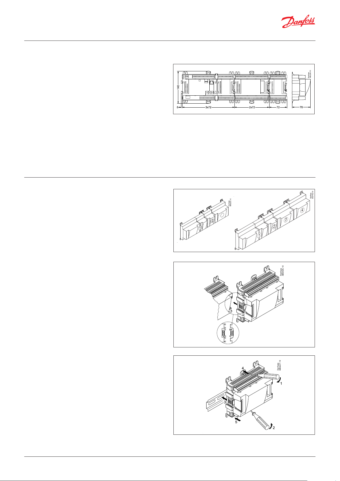
8. Length
If you use many extension modules, the controller’s length will
grow accordingly. The row of modules is a complete unit which
cannot be broken.
If the row becomes longer than desired, the row can be broken by
using AK-CM 102.
The module dimension is 72 mm.
Modules in the 100-series consist of one module.
Modules in the 200-series consist of two modules.
The controller consist of three modules.
The length of an aggregate unit = n x 72 + 8
or in an other way:
Module Type No. at Length
Controller module 1 x 224 = 224 mm
Extension module 200-series _ x 144 = ___ mm
Extension module 100-series _ x 72 = ___ mm
Total length = ___ mm
9. Linking of modules
Start with the controller module and then mount the selected
extension modules. The sequence is of no importance.
However, you must not change the sequence, i.e. rearrange the
modules, after you have made the set-up where the controller
is told which connections are found on which modules and on
which terminals.
The modules are attached to one another and kept together by a
connection which at the same time transmits the supply voltage
and the internal data communication to the next module.
Mounting and removal must always be performed when there is
no voltage.
The protective cap mounted on the controller’s plug connection
must be moved to the last vacant plug connection so that the plug
will be protected against short-circuit and dirt.
Example continued:
Controller module + 2 extension modules in 200-series + 1
extension module in 100 series =
224 + 144 + 144 + 72 = 584 mm.
Example continued
When the regulation has started, the controller will check all the
time whether there is connection to the connected modules. This
status can be followed by the light-emitting diode.
When the two catches for the DIN rail mounting are in open
position, the module can be pushed into place on the DIN rail – no
matter where in the row the module is found.
Removal is likewise carried out with the two catches in the open
position.
© Danfoss | Climate Solutions | 2022.02 BC245386497365en-000801 | 35
Page 36
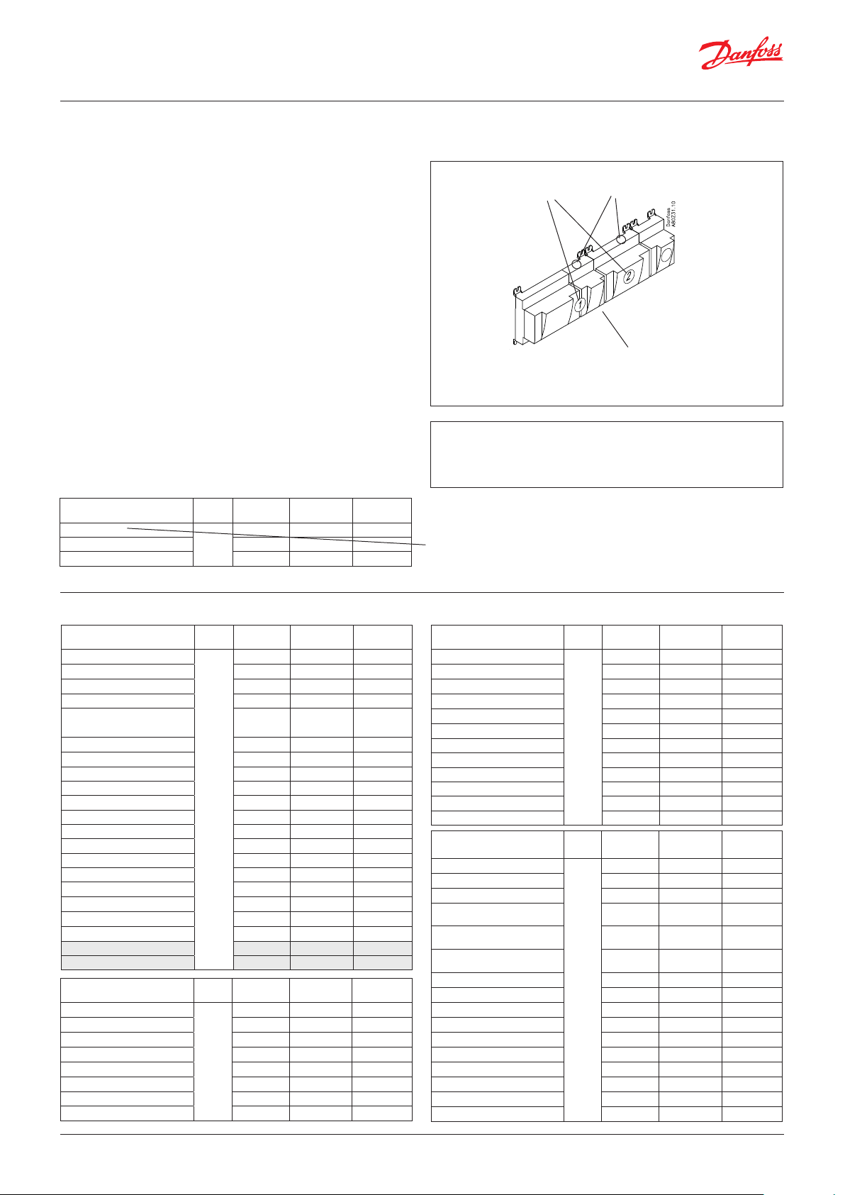
User Guide | Pack controller, type AK-PC 782A
10. Determine the connection points
All connections must be programmed with module and point, so
in principle it does not matter where the connections are made, as
long as it takes place on a correct type of input or output.
• The controller is the first module, the next one is 2, etc.
• A point is the two or three terminals belonging to an input or
output (e.g. two terminals for a sensor and three terminals for a
relay).
The preparation of the connection diagram and the subsequent
programming (configuration) should take place at the present
time. It is most easily accomplished by filling in the connection
survey for the relevant modules.
Principle:
Name On module On Point Function
fx Compressor 1 x x Close
fx Compressor 2 x x Close
fx Alarm relay x x NC
fx Main switch x x Close
fx P0 x x AKS 2050-1 to 159 bar
Module Point
Mind the numbering.
The right-hand part of the
controller module may look like a
separate module. But it is not.
The connection survey from the controller and any extension
modules are uploaded from the paragraph "Module survey. E.g.
controller module:
Signal Module Point Terminal
1 (AI 1) 1 - 2
2 (AI 2) 3 - 4
3 (AI 3) 5 - 6
Example continued
Signal Module Point
Discharge temperature - Sd-MT
Suction gas temperature- Ss-MT 2 (AI 2) 3 - 4 Pt 1000
Discharge temperature - Sd-IT 3 (AI 3) 5 - 6 Pt 1000
Suction gas temperature- Ss-MT 4 (AI 4) 7 - 8 Pt 1000
Thermostat sensor in plant room
- Saux1
Suction pressure - P0-MT 6 (AI 6) 11 - 12 AKS 2050-59
Condensing pressure - Pc-MT 7 (AI 7) 13 - 14 AKS 2050-159
Tap water temperature - Stw8 8 (AI 8) 19 - 20 Pt 1000
Temp. gas cooler output Sgc 9 (AI 9) 21 - 22 Pt 1000
Gas cooler pressure Pgc 10 (AI 10) 23 - 24 AKS 2050-159
Refrigerant receiver, Prec CO
Hot gas dump 12 (DO 1) 31 - 32 ON
Circulation pump tw 13 (DO 2) 33 - 34 ON
MT Compressor 1 (VLT start) 16 (DO 5) 39 - 40 - 41 ON
MT Compressor 2 17 (DO6) 42 - 43 - 44 ON
MT Compressor 3 18 (DO7) 45 - 46 - 47 ON
IT Compressor (VLT start) 19 (DO8) 48 - 49 - 50 ON
Speed control MT compressor 24 - 0-10 V
Speed control IT compressor 25 - 0-10 V
Signal
Temp. by-pased gas Shp
Level switch, CO2 receiver 2 (AI 2) 3 - 4 Open
Start/stop heat recovery tw 3 (AI 3) 5 - 6 Closed
Outdoor temperature, Sc3 4 (AI 4) 7 - 8 Pt 1000
Speed control LT compressor 5 (AO 1) 9 - 10 0 - 10 V
Speed control, gas cooler fan 6 (AO 2) 11 - 12 0 - 10 V
Speed control, pump - tw 7 (AO 3) 13 - 14 0 - 10 V
2
Module Point
1 (AI 1) 1 - 2 Pt 1000
5 (AI 5) 9 - 10 Pt 1000
1
11 (AI 11) 25 - 26 AKS 2050-159
14 (DO 3) 35 - 36
15 (DO 4) 37 - 38
1 (AI 1) 1 - 2 Pt 1000
2
8 (AO 4) 15 - 16
Terminal
Terminal
Signal type /
Active at
Signal type /
Active at
Signal type /
Active at
Note: The safety relays should not be fitted onto a module
with override changeovers, as they can be put out of
operation by an incorrect setting.
- Columns 1, 2, 3 and 5 are used for the programming.
- Columns 2 and 4 are used for the connection diagram.
Signal
MT compressor 1 safety circuits
MT compressor 2 safety circuits 2 (AI 2) 3 - 4 Open
MT compressor 3 safety circuits 3 (AI 3) 5 - 6 Open
LT compressor 1 safety circuits 5 (AI 5) 9 - 10 Open
LT compressor 2 safety circuits 6 (AI 6) 11 - 12 Open
Heat recovery tw2 7 (AI 7) 13 - 14 Pt 1000
Heat recovery tw3 8 (AI 8) 15 - 16 Pt 1000
Signal to by-pass valve, Vrec 9 (step 1) 25 - 26 - 27 - 28 CCMT
Signal to high pressure valve, Vhp 10 (step 2)
Signal to 3-way valve V3gc 11 (step 3) 33 - 34 - 35 - 36 CTR
Signal Module Point
Discharge temperature - Sd-LT
Suction gas temperature - Ss-LT 2 (AI 2) 3 - 4 Pt 1000
External main switch 3 (AI 3) 5 - 6 Closed
MT Compressors common safety
circuits
IT Compressors common safety
circuits
LT Compressors common safety
circuits
Heat recovery tw4 7 (AI 7) 17 - 18
Suction pressure - P0-LT 8 (AI 8) 19 - 20 AKS 2050-59
LT Compressor 1 (VLT start) 9 (DO 1) 25 - 26 - 27 ON
LT Compressor 2 10 (DO 2) 28 - 29 - 30 ON
Fan motors (VLT start) 11 (DO 3) 31 - 32 - 33 ON
3-way valve, tap water, Vtw 13 (DO 5) 37 - 38 - 39 ON
Room fan 15 (DO7) 43 - 44 - 45 ON
Module Point
1 (AI 1) 1 - 2 Open
4 (AI 4) 7 - 8
3
12 (step 4) 37 - 38 - 39 - 40
1 (AI 1) 1 - 2 Pt 1000
4 (AI 4) 7 - 8 Open
5 (AI 5) 13 - 14
6 (AI 6) 15 - 16
4
12 (DO 4) 34 - 35 - 36
14 (DO6) 40 - 41 - 42
16 (DO8) 46 - 47 - 48
Terminal
29 - 30 - 31 - 32
Terminal
Signal type /
Active at
CCMT
Signal type /
Active at
Open
Open
Pt 1000
36 | BC245386497365en-000801 © Danfoss | Climate Solutions | 2022.02
Page 37

User Guide | Pack controller, type AK-PC 782A
11. Connection diagram
Drawings of the individual modules may be ordered from Danfoss.
Format = dwg and dxf.
You may then yourself write the module number in the circle and
draw the individual connections.
Example continued:
The supply voltage for the pressure transmitter should be taken
from the same module that receives the pressure signal.
The screen on the pressure transmitter cables must only be
connected at the end of the controller.
© Danfoss | Climate Solutions | 2022.02 BC245386497365en-000801 | 37
Page 38

User Guide | Pack controller, type AK-PC 782A
12. Supply voltage
Supply voltage is only connected to the controller module. The
supply to the other modules is transmitted via the plug between
the modules.
The supply must be 24 V +/-20%. One power supply must be used
for each controller. The power supply must be a class II.
The 24 V must not be shared by other controllers or units. The
analogue inputs and outputs are not galvanically separated from
the supply.
The + and – 24V input must not be earthed.
If using stepper motor valves, the supply for these must be
provided from a separate power supply.
For CO facilities, it will also be necessary to safeguard the voltage
to the controller and valves using UPS.
Example continued:
Controller module 8 VA
+ 2 extension modules in 200 series 10 VA
+ 1 extension module in 100 series 2 VA
------
Power supply size (least) 20 VA
+ Separate power supply for the module with the stepper motors:
7,8 + 1,3 + 1,3 + 5,1 = 15,5 VA.
Power supply size
The power consumption grows with the number of modules used:
Module Type No. á Effect
Controller 1 x 8 = 8 VA
Extension module 200 series _ x 5 = _ VA
Extension module 100 series _ x 2 = _ VA
Total _ VA
Common pressure transmitter
If several controllers receive a signal from the same pressure
transmitter, the supply to the affected controllers must be wired so
that it is not possible to switch off one of the controllers without
also switching off the others. (If one controller is switched off, the
signal will be pulled down, and all the other controllers will receive
a signal which is too low)
38 | BC245386497365en-000801 © Danfoss | Climate Solutions | 2022.02
Page 39
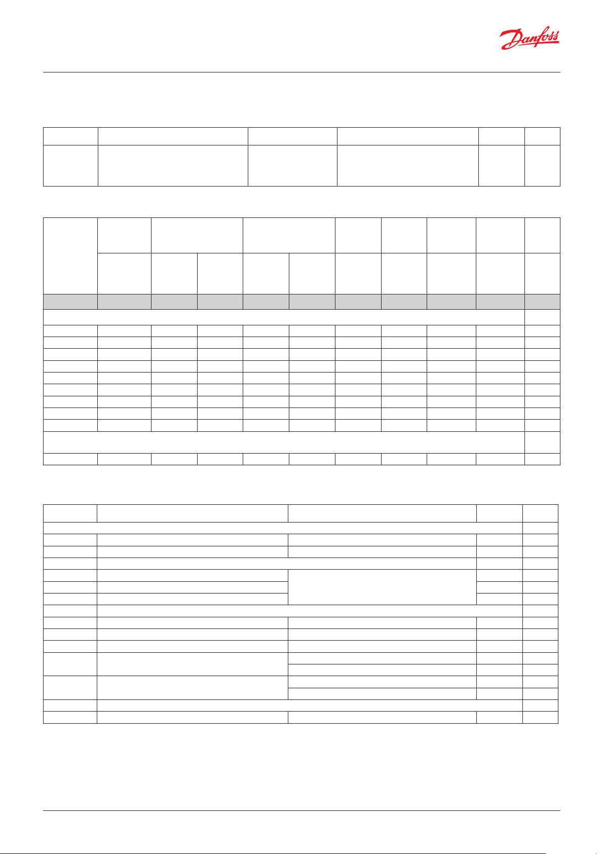
User Guide | Pack controller, type AK-PC 782A
2.6 Ordering
1. Controller
Type Function Application Language Code no.
AK-PC 782A
Controller for capacity control of MT-, LT-,
IT- compressors and condensers. With oil
management, multi ejector and high pressure regulation
Transcritical CO2
booster control
English, German, French, Dutch, Italian,
Spanish, Portuguese, Danish, Finnish,
Russian, Czech, Polish
080Z0192
2. Extension modules and survey for inputs and outputs
Type Analogue
inputs
For sensors,
pressure
transmitters
etc.
Controller 11 4 4 - - - - -
Extension modules
AK-XM 101A 8 080Z0007
AK-XM 102A 8 080Z0008
AK-XM 102B 8 080Z0013
AK-XM 103A 4 4 080Z0032 x
AK-XM 204A 8 080Z0011
AK-XM 204B 8 x 080Z0018
AK-XM 205A 8 8 080Z0010 x
AK-XM 205B 8 8 x 080Z0017
AK-XM 208C 8 4 080Z0023 x
The following extension module can be placed on the PC board in the controller module.
There is only room for one module.
AK-OB 110 2 080Z0251 x
On/Off outputs On/off supply voltage
(DI signal)
Relay
(SPDT)
Solid state Low volt-
age
(max. 80 V)
High voltage
(max. 260
V)
Analogue
outputs
Stepper
outputs
0-10 V DC For valves
with step
control
Module
with
switches
For override
of relay
outputs
Code no.
With screw
terminals
continued
continued
Example
X
Example
3. AK operation and accessories
Type Function Application Code no.
Operation
AK-ST 500 Software for operation of AK controllers AK-operation 080Z0161 x
- Cable between PC and AK controller USB A-B (standard IT cable) - x
Accessories Power supply module 230 V / 115 V to 24 V DC
AK-PS 075 18 VA
AK-PS 150 36 VA 080Z0054 x
Supply for controller
080Z0053 x
AK-PS 250 60 VA 080Z0055
Accessories External display that can be connected to the controller module. For showing, say, the suction pressure
EKA 163B Display 084B8574
EKA 164B Display with operation buttons 084B8575
MMIGRS2 Graphic display with operation 080G0294
- Cable between EKA display and controller
-
Cable between graphic display type MMIGRS2 and
controller (controller with RJ11 plug)
Length = 2 m 084B7298
Length = 6 m 084B7299
Length = 1.5 m 080G0075
Length = 3 m 080G0076
Accessories Communication modules for controllers where modules cannot be connected continuously
AK-CM 102 Communication module Data communication for external extension modules 080Z0064
continued
Example
© Danfoss | Climate Solutions | 2022.02 BC245386497365en-000801 | 39
Page 40
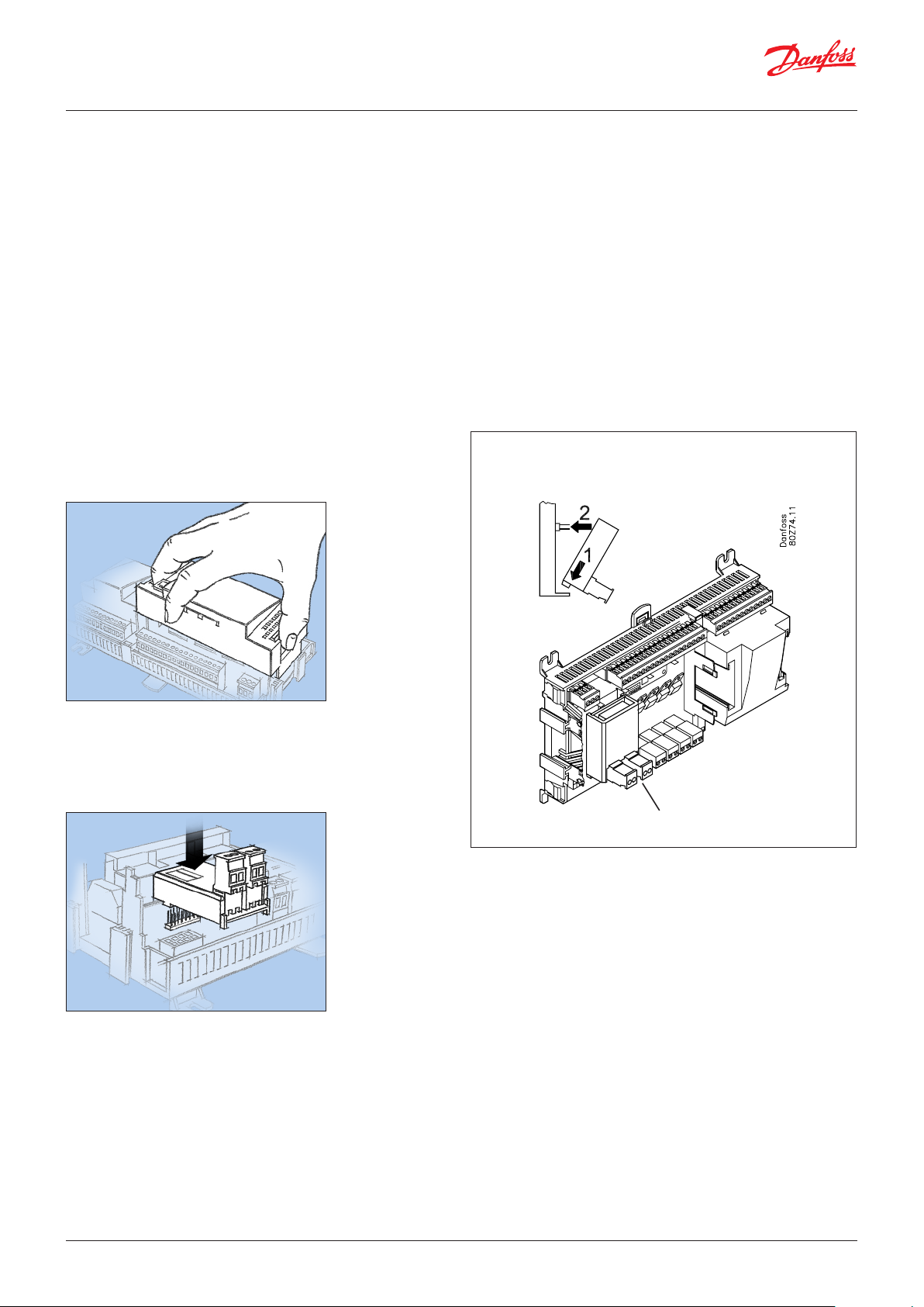
User Guide | Pack controller, type AK-PC 782A
3. Mounting and wiring
This section describes how the controller:
• is fitted
• is connected
We have decided to work on the basis of the example we went
through previously, i.e. the following modules:
• AK-PC 782A controller module
• AK-XM 205A input and output module
• AK-XM 208C analogue input module + stepper output module
• AK-XM 103B analogue input and output module
• AK-OB 110 analogue output module
3.1 Mounting
Mounting of analogue output module
The basic module must not be connected to voltage.
1. Lift the top part off the basic module
The analogue extension module will supply a signal to
frequency converter on MT and IT.
Press in the plate on the left-hand side of the light-emitting
diodes and the plate on the right-hand side for the red address
changers.
Lift the top part off the basic module.
2. Mount the extension module in the basic module
3. Put the top part back onto the basic module
There are two outputs.
40 | BC245386497365en-000801 © Danfoss | Climate Solutions | 2022.02
Page 41

User Guide | Pack controller, type AK-PC 782A
Mounting of extension module on the basic module
1. Move the protective cap
1. Remove the protective cap from the connection plug on the
right-hand side of the basic module.
Place the cap on the connection plug to the right of the extension
module that is to be mounted on the extreme right-hand side of
the AK assembly.
2. Assemble the extension module and the basic module.
The basic module must not be connected to voltage.
In our example, three extension modules are to be fitted to the
basic module. We have chosen to fit the module with analogue
outlets directly on the basic module and then the following
module. The sequence is thus:
All the subsequent settings that affect the three extension
modules are determined by this sequence.
When the two snap catches for the DIN rail mounting are in
the open position, the module can be pushed into place on
the DIN rail – regardless of where the module is on the row.
Disassembly is thus done with the two snap catches in the
open position.
© Danfoss | Climate Solutions | 2022.02 BC245386497365en-000801 | 41
Page 42

Mounting and wiring - continued
User Guide | Pack controller, type AK-PC 782A
3.2 Wiring
Decide during planning which function is to be connected and
where this will be.
1. Connect inputs and outputs
Here are the tables for the example:
Signal Module Point
Discharge temperature - Sd-MT
Suction gas temperature- Ss-MT
Discharge temperature - Sd-IT
Suction gas temperature- Ss-MT 4 (AI 4) 7 - 8 Pt 1000
Thermostat sensor in plant room
- Saux1
Suction pressure - P0-MT 6 (AI 6) 11 - 12 AKS 2050-59
Condensing pressure - Pc-MT 7 (AI 7) 13 - 14 AKS 2050-159
Tap water temperature - Stw8 8 (AI 8) 19 - 20 Pt 1000
Temp. gas cooler output Sgc 9 (AI 9) 21 - 22 Pt 1000
Gas cooler pressure Pgc 10 (AI 10) 23 - 24 AKS 2050-159
Refrigerant receiver, Prec CO
Hot gas dump 12 (DO 1) 31 - 32 ON
Circulation pump tw 13 (DO 2) 33 - 34 ON
MT Compressor 1 (VLT start) 16 (DO 5) 39 - 40 - 41 ON
MT Compressor 2 17 (DO6) 42 - 43 - 44 ON
MT Compressor 3 18 (DO7) 45 - 46 - 47 ON
IT Compressor (VLT start) 19 (DO8) 48 - 49 - 50 ON
Speed control MT compressor 24 - 0-10 V
Speed control IT compressor 25 - 0-10 V
2
1 (AI 1) 1 - 2 Pt 1000
2 (AI 2) 3 - 4 Pt 1000
3 (AI 3) 5 - 6 Pt 1000
5 (AI 5) 9 - 10 Pt 1000
1
11 (AI 11) 25 - 26 AKS 2050-159
14 (DO 3) 35 - 36
15 (DO 4) 37 - 38
Terminal
Signal type /
Active at
Remember the isolation amplifier.
If signals are received from different controls, e.g. heat recovery
for one of the inputs, a galvanically insulated module should be
inserted.
The function of the switch functions can be seen in the last
column.
There are pressure transmitters AKS 32R and AKS 2050
available for several pressure ranges.
Here there are two different ones. One up to 59 bar and two
up to 159 bar.
Signal
Temp. by-pased gas Shp
Level switch, CO2 receiver 2 (AI 2) 3 - 4 Open
Start/stop heat recovery tw 3 (AI 3) 5 - 6 Closed
Outdoor temperature, Sc3 4 (AI 4) 7 - 8 Pt 1000
Speed control LT compressor 5 (AO 1) 9 - 10 0 - 10 V
Speed control, gas cooler fan 6 (AO 2) 11 - 12 0 - 10 V
Speed control, pump - tw 7 (AO 3) 13 - 14 0 - 10 V
Signal
MT compressor 1 safety circuits
MT compressor 2 safety circuits 2 (AI 2) 3 - 4
MT compressor 3 safety circuits 3 (AI 3) 5 - 6 Open
LT compressor 1 safety circuits 5 (AI 5) 9 - 10 Open
LT compressor 2 safety circuits 6 (AI 6) 11 - 12 Open
Heat recovery tw2 7 (AI 7) 13 - 14 Pt 1000
Heat recovery tw3 8 (AI 8) 15 - 16 Pt 1000
Signal to by-pass valve, Vrec 9 (step 1) 25 - 26 - 27 - 28 CCM T
Signal to high pressure valve, Vhp 10 (step 2) 29 - 30 - 31 - 32 CCMT
Signal to 3-way valves V3gc 11 (step 3) 33 - 34 - 35 - 36 C TR
Module Point
1 (AI 1) 1 - 2 Pt 1000
2
8 (AO 4) 15 - 16
Module Point
1 (AI 1) 1 - 2
4 (AI 4) 7 - 8 Open
3
12 (step 4) 37 - 38 - 39 - 40
Terminal
Terminal
Signal type /
Active at
Signal type /
Active at
Open
Open
Signal Module Point
Discharge temperature - Sd-LT
Suction gas temperature - Ss-LT 2 (AI 2) 3 - 4 Pt 1000
External main switch 3 (AI 3) 5 - 6 Closed
MT Compressors common safety
circuits
IT Compressors common safety
circuits
LT Compressors common safety
circuits
Heat recovery tw4 7 (AI 7) 17 - 18 Pt 1000
Suction pressure - P0-LT 8 (AI 8) 19 - 20 AKS 2050-59
LT Compressor 1 (VLT start) 9 (DO 1) 25 - 26 - 27 ON
LT Compressor 2 10 (DO 2) 28 - 29 - 30 ON
Fan motors (VLT start) 11 (DO 3) 31 - 32 - 33 ON
3-way valve, tap water, Vtw 13 (DO 5) 37 - 38 - 39 ON
Room fan 15 (DO7) 43 - 44 - 45 ON
1 (AI 1) 1 - 2 Pt 1000
4 (AI 4) 7 - 8 Open
5 (AI 5) 13 - 14 Open
6 (AI 6) 15 - 16 Open
4
12 (DO 4) 34 - 35 - 36
14 (DO6) 40 - 41 - 42
16 (DO8) 46 - 47 - 48
Terminal
Signal type /
Active at
42 | BC245386497365en-000801 © Danfoss | Climate Solutions | 2022.02
Page 43

User Guide | Pack controller, type AK-PC 782A
The connections for the example can be seen here.
Warning!
Keep signal cables separate from
cables with high voltage.
The screen on the pressure
transmitter cables must only
be connected at the end of the
controller.
The supply voltage for the
pressure transmitter should be
taken from the same module
that receives the pressure
signal.
Remember separate power
supply for AK-XM 208C.
© Danfoss | Climate Solutions | 2022.02 BC245386497365en-000801 | 43
Page 44
User Guide | Pack controller, type AK-PC 782A
2. Connect LON communication network
The installation of the data communication must comply with the
requirements set out in document RC8AC.
3. Connect supply voltage
The supply voltage is 24 V, and the supply must not be used by
other controllers or devices. The terminals must not be earthed.
4. Follow light-emitting diodes
When the supply voltage is connected, the controller will go
through an internal check. The controller will be ready in just
under one minute when the light-emitting diode ”Status” starts
flashing slowly.
5. When there is a network
Set the address and activate the Service Pin.
6. The controller is now ready to be configured.
Internal communication
between the modules:
Quick flash = error
Constantly On = error
n Power
n Comm
n DO1 n Status
n DO2 n Service Tool
n DO3 n LON
n DO4 n I/O extension
n DO5 n Alarm
n DO6
n DO7 n Display
n DO8 n Service Pin
Status on output 1-8
Slow flash = OK
Quick flash = answer from gateway in 10 min.
after network installation
Constantly ON = error
Constantly OFF = error
External communication
Communication to AK-CM 102
Flash = active alarm/not cancelled
Constant ON = Active alarm/cancelled
Network installation
44 | BC245386497365en-000801 © Danfoss | Climate Solutions | 2022.02
Page 45
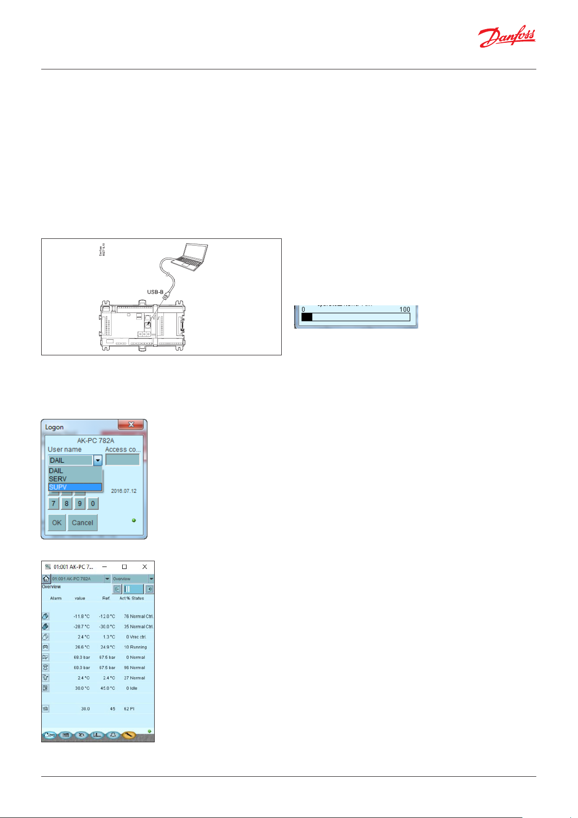
User Guide | Pack controller, type AK-PC 782A
4. Configuration and operation
This section describes how the controller:
• is configured
• is operated
We have decided to work on the basis of the example we went
through previously, i.e. MT-, LT-, IT-control, high pressure control,
heat recovery and gas cooler.
4.1 Configuration
4.1.1 Connect PC
PC with the program “Service Tool” is connected to the controller.
For connecting and operating the "AK service tool"
software, please see the manual for the software.
The first time the Service Tool is connected to a new version
of a controller, the start-up of the Service Tool will take longer
than usual while information is retrieved from the controller.
Time can be followed on the bar at the bottom of the display.
The controller must be switched on first and the LED “Status” must
flash before the Service Tool program is started.
Start Service Tool programme
Login with user name SUPV
Select the name SUPV and key in the access code.
When the controller is supplied the SUPV access code is 123.
When you are logged into the controller, an overview of it will
always appear.
In case the overview is empty: this is because the controller
has not yet been set up.
The red alarm bell at the bottom right tells you that there is an
active alarm in the controller. In our case the alarm is due to
the fact that the time in the controller has not yet been set.
© Danfoss | Climate Solutions | 2022.02 BC245386497365en-000801 | 45
Page 46

User Guide | Pack controller, type AK-PC 782A
Refrigerating plant example:
We have decided to describe the setup by means of an example
comprising an MT-, LT- and IT group.
The example is the same as the one given in the "Design" section,
i.e. the controller is an AK-PC 782A + extension modules.
Compressor Group
MT circuits
• 3 compressors with "cyclic". One speed controlled
• Safety monitoring of each compressor
• Common high-pressure monitoring
• Po setting -10°C, Po optimization from the system unit
LT circuits
• 2 x compressors with "cyclic". One speed controlled
• Safety monitoring of each compressor
• Common high pressure monitoring
• Po setting –30°C, Po optimization from the system unit
IT circuit
• 1 compressor, speed controlled
• Receiver set point 36 bar
High pressure controls:
• Heat recovery for tap water
• Gas cooler
• Fans, speed controlled
Receivers:
• Optimal CO reveiver pressure
• Monitoring CO-level in the receiver
• Monitoring of high and low pressure
• Controlling the tap water receiver temperature, 55°C
Fan in plant room
• Thermostat control of fan in engine room
Safety functions:
• Monitoring of Po, Pc, Sd and superheat in suction line
• MT: Po max = -5°C, Po min = -35°C
• MT: Pc max = 110 bar
• MT: Sd max = 120°C
• LT: Po max = -5°C, Po min = -45°C
• LT: Pc max = 40 bar
• LT: Sd max = 100°C
• SH min = 5 °C, SH max = 35 °C
Other:
• Start/stop of heat recovery to Tw
• External main switch used
There is also an internal main switch as a setting. Both this and the
external main switch must be “ON” before any adjustment is made.
Warning!
The main switch will stop all regulations, including high-pressure
regulation.
46 | BC245386497365en-000801 © Danfoss | Climate Solutions | 2022.02
Page 47

User Guide | Pack controller, type AK-PC 782A
4.1.2 Authorization
1. Go to Configuration menu
Press the orange set-up button with the spanner at the bottom
of the display.
When the controller is supplied, it has been set with standard
authorization for different user interfaces. This setting should
be changed and adapted to the plant. The changes can be
made now or later.
2. Select Authorization
3. Change setting for the user ‘SUPV‘
You will use this button again and again whenever you want
to get to this display.
On the left-hand side are all the functions not shown yet.
There will be more here the further into the set-up we go.
Press the line Authorization to get to the user set-up display.
Mark the line with the user name SUPV.
Press the button Change.
4. Select user name and access code
This is where you can select the supervisor for the specific
system and a corresponding access code for this person.
The controller will utilize the same language that is selected
in the service tool but only if the controller contains this
language. If the language is not contained in the controller,
the settings and readings will be shown in English.
5. Carry out a new login with the user name and the new access code
To activate the new settings you must carry out a new login
to the controller with the new user name and the relevant
access code.
You will access the login display by pressing the icon at the
top left corner of the display.
© Danfoss | Climate Solutions | 2022.02 BC245386497365en-000801 | 47
Page 48
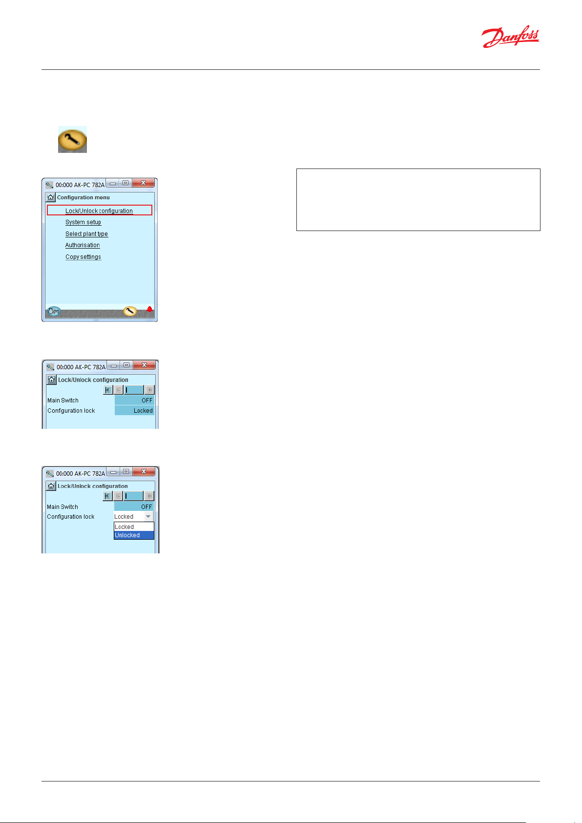
User Guide | Pack controller, type AK-PC 782A
4.1.3 Unlock the configuration of the controllers
1. Go to Configuration menu
2. Select Lock/Unlock configuration
3. Select Configuration lock
Press the blue field with the text Locked
The controller can only be configured when it is unlocked.
The values can be changed when it is locked, but only for
those settings that do not affect the configuration.
4. Select Unlocked
Select Unlocked.
48 | BC245386497365en-000801 © Danfoss | Climate Solutions | 2022.02
Page 49
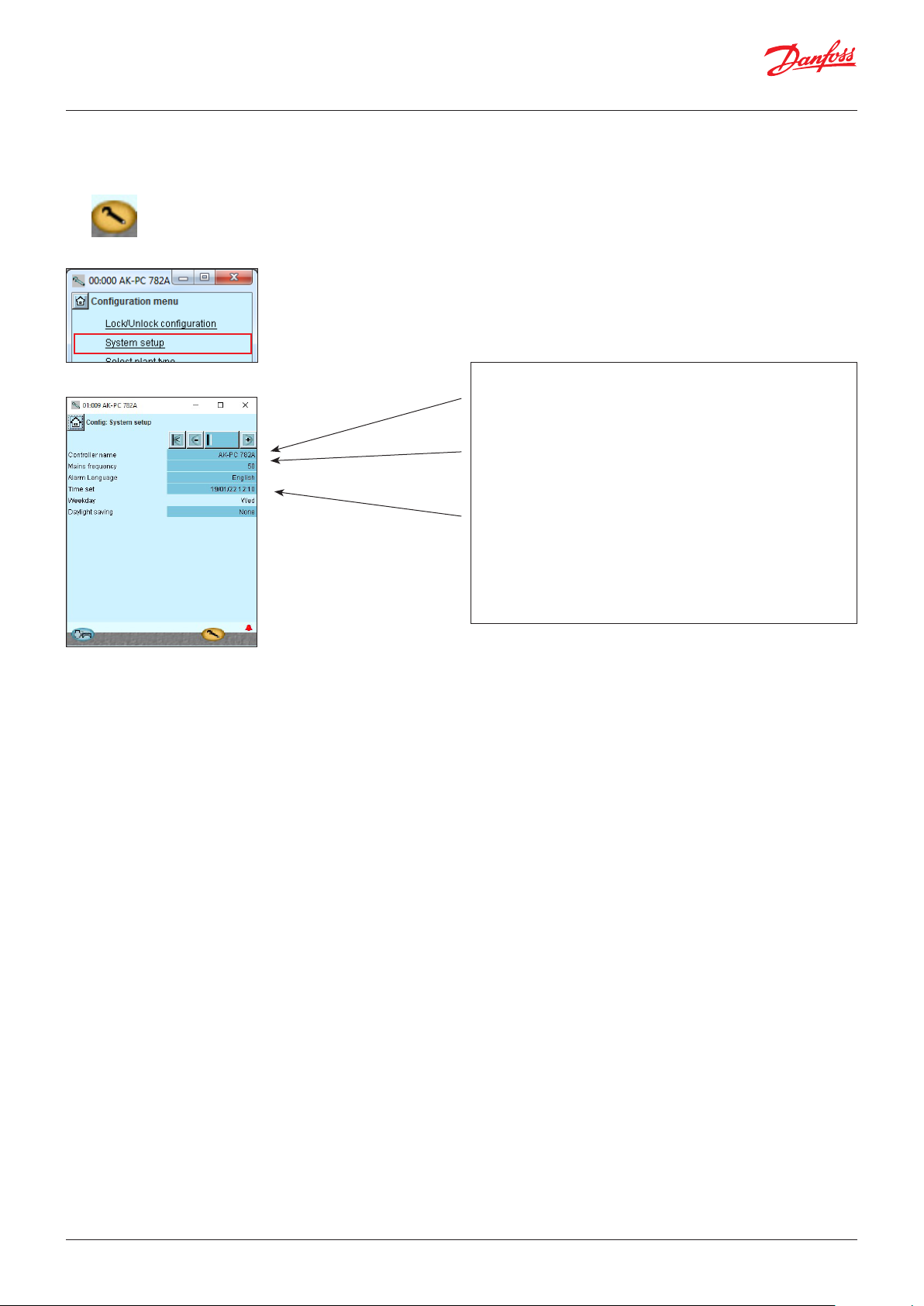
User Guide | Pack controller, type AK-PC 782A
4.1.4 System set-up
1. Go to Configuration menu
2. Select System setup
3. Set system settings
All settings can be changed by pressing in the blue field with
the setting and then indicating the value of the required
setting.
In the first field you enter a name for what the controller will
be controlling. The text written in this field can be viewed at
the top of all screens, together with the controller's address.
When the time is set, the PC’s time can be transferred to the
controller.
When the controller is connected to a network, date and time
will automatically be set by the system unit in the network.
This also applies to change-over Daylight saving.
In case of power failure, the clock will be kept running for at
least 12 hours.
© Danfoss | Climate Solutions | 2022.02 BC245386497365en-000801 | 49
Page 50
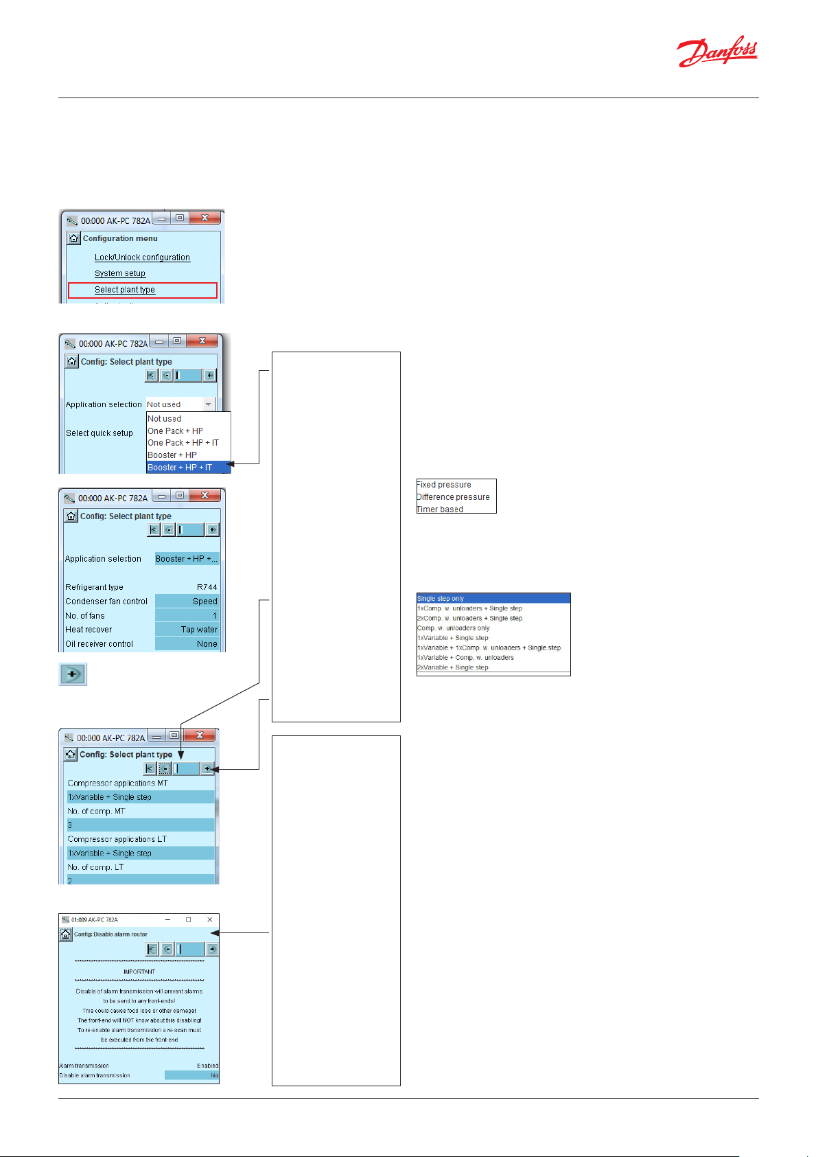
User Guide | Pack controller, type AK-PC 782A
4.1.5 Set plant type
1. Go to Configuration menu
2. Select plant type
Press the line Select plant type.
3. Set plant type
Press the + button to go to the
next page
4. Further plant settings
5. Disable alarm router
General:
If you want to know more about the different configuration options, they are listed in the right column.
The number refers to the number and picture in the column on the left.
As the screen only shows the settings and readings that are required for a given set-up, all possible settings have
also been included in the right column.
Our example:
The comments for the
example are shown on the
following pages, in the middle column.
In our example, the
controller must regulate
a Booster System, High
Pressure Control and IT
Compressor.
Subsequent options are
then available, but only
those options allowed by
the current selection.
The settings for our
example can be viewed in
the display.
There are several
underlying pages.
The black bar in this
field tells you which of
the pages is currently
displayed.
Browse the pages using
the + and - buttons.
Alarm transmission to
the front-end can be
disabled. This can be
used to avoid “Alarm
Router full” message
when the controller is
disconnected from the
front-end. The menu can
only be accessed if “show
advanced settings” is
enabled (present under
“Select plant type”).
To reenable the alarm
transmission a re-scan
must be executed from
the front-end.
Note: The alarm
transmission should only
be disabled with great
care as critical alarms will
not be transmitted to
the front-end. This could
result in food loss or other
damage.
3 - Plant type
Application selection
Select between one of the 4 applications where:
HP = High pressure control. MT=middle temperature. LT=low temperature.
IT=parallel compression
3- after application selection
Refrigerant
Only for CO systems. The refrigerant cannot be changed
Condenser fan control
Fan control is defined here:
Step, step+speed, just speed or speed for the first fan+step for the rest
No of fans
Set the number of relay outputs that will be used
Heat recovery
Heat recovery enabled
Domestic water, room heating or both
To be set later
Oil management
Oil control enabled
Choose between:
Select quick set-up
Here, you can reset all the controller settings back to the factory settings
4 - Additional system definitions
Compressor combinations
No of compressors
Set the number of compressor units that will be used
External main switch
A switch may be connected for starting and stopping the regulation. (Also
opens UPS selection)
Mon. Ext. Power loss (signal from an UPS)
Monitoring of external voltage. When selecting "yes", a digital input is
allocated
Alarm output
Here you may set whether or not it should be an alarm relay, and which
priorities will activate it
I'm alive relay
A relay will "release" if the regulation fails
Night selected via DI
The switch to night mode takes place when the signal is received
Show advanced settings
This function opens the advanced settings in the various menus
Comp. cap. out to AO
If selecting "yes", an analogue output indicates the running capacity
50 | BC245386497365en-000801 © Danfoss | Climate Solutions | 2022.02
Page 51

User Guide | Pack controller, type AK-PC 782A
4.1.6 Set control of suction group MT
1. Go to Configuration menu
2. Select Suction group
3. Set values for the reference
Press the + button to go to the
next page
4. Set values for capacity control
The configuration menu
in the Service Tool has
changed now. It shows
the possible settings for
the selected plant type.
In our example we
select the settings:
- P0 optimization
- Suction set point =
-10 °C
The settings are shown
here in the display.
3 - Reference mode
Displacement of suction pressure as a function of external signals
0: Reference = set reference + night offset + offset from external
0-10 V signal
1: Reference = set reference + offset from P0 optimization
Setpoint ( -80 – 30°C)
Setting of required suction pressure in °C
Offset via Ext. Ref
Select whether a 0-10V external reference override signal is
required
Offset at max input (-100 – 100 °C)
Displacement value at max. signal (10)
Offset at min input (-100 – 100 °C)
Displacement value at min. signal (0 V)
Offset filter (10 - 1800 Sec)
Here you can set how quickly the reference must become effective
Night Offset via DI
Select whether a digital input is required for activation of night
operation. Night operation can alternatively be controlled via
internal weekly schedule or via a network signal
Night Offset (-25 – 25 K)
Displacement value for suction pressure in connection with an
active night setback signal (set in Kelvin)
Max reference (-50 – 80 °C)
Max. permissible suction pressure reference
Min reference (-80 – 25 °C)
Min. permissible suction pressure reference
4 - Compressor application
Select one of the available compressor configurations here:
Press the + button to go to the
next page
If a "Variable" or "screw
compressor" is chosen
in the first line, its type
must be determined in
the next line.
In our example we
select:
-VSD + single step
- 3 compressors
- Cyclic
Note: The two
parameters ‘Control
sensor’ and ‘Psuc
max offset’ are used
to configure an
application with Low
Pressure Multi Ejectors.
They are only visible
when no IT suction
group has been
defined“.
Lead compressor type
• Variable
The following options are available for variable:
No. of compressors
Set number of compressors (total)
No. of unloaders
Set number of unloader valves
Ext. compressor stop
An external switch can be connected which will start and stop the
compressor control
Control sensor
Select the sensor for the compressor controller:
- “Po-MT” to control on the Po-MT
sensor
- “Po-MT + Psuc-MT” to control both “Po-MT” and “Psuc-MT”. The
compressors will be controlled on the sensor that is most above
to its reference
Psuc max offset
Set the difference between Psuc-MT and Po-MT references
Step control mode
Select coupling pattern for compressors:
Cyclic: Runtime equalisation between compressors (FIFO)
Best fit: Compressors are cut in/out in order to make the best
possible fit to actual load
© Danfoss | Climate Solutions | 2022.02 BC245386497365en-000801 | 51
Page 52

User Guide | Pack controller, type AK-PC 782A
External coordination MT/LT
Select "yes" if you want to coordinate with an external LT controller
Ext. Coordination MT/LT
Visible if the controller is configured as "One pack + HP" ("plant
type" "application selection").
MT/LT coordination is automatically enabled for booster packs. For
“One pack” applications, it can be enabled to operate using DI/DO.
MT/LT coord. threshold
Select when to start the MT compressor:
• “Neutral zone” to start when Po is in or above the neutral zone.
• “Reference” to start when above the Po reference.
• “Plus zone” to start when Po is in the plus zone.
LT coord. stop
Select when to stop the LT compressors:
• “MT compr.” to stop when MT is not ready.
• “MT Po” to stop when MT should start but is not ready.
Pump down
Select whether a pump down function is required on the last
running compressor
Synchronous speed
No: There will be two analogue outputs available.
Yes: There will be one analogue output.
Early stop enable
Select this to limit the time that the last compressor is allowed to
run inside the minus zone
Early stop delay
Set the maximum time that the last compressor is allowed to run
inside the minus zone.
Pump down limit Po (-80 – +30 °C)
Set the actual pump down limit
VSD min speed (0.5 – 60 Hz)
Min. speed where the compressor must cut out
VSD start speed (20 – 60 Hz)
Minimum speed for start of Variable speed drive (must be set
higher than “VSD Min. Speed Hz”)
VSD max speed (40 – 120 Hz)
Highest permissible speed for the compressor motor
VSD safety monitoring
Select this if input for monitoring of the frequency converter is required
PWM period time
Period time for by-pass valve (on time + off time)
PWM Min. capacity
Minimum capacity in the period time (without a minimum
capacity the compressor will not be cooled)
PWM Start capacity
Minimum capacity at which the compressor will start (must be set
to a higher value than "PWM Min. capacity")
Load shed limits
Select which signal to be used for load limitation
(only via network, a DI + network or two DI + network)
Load limitation period
Set the maximum time permitted for load limitation
Load shed limit 1
Set max. capacity limit for load shed input 1
Load shed limit 2
Set max. capacity limit for load shed input 2
Override limit T0
Any load below the limit value is freely permitted. If the T0 exceeds
the value, a time delay is started. If the time delay runs out, the
load limit is cancelled
Override delay 1
Max. time for load shed limit, if T0 is too high
Override delay 2
Max. time for load shed limit, if T0 is too high
Easy PI Selection
Group setting for the 4 control parameters: Kp, Tn, + acceleration
and - acceleration. If the setting is set to “user defined” the 4
control parameters can be fine-tuned:
Kp To (0.1 – 10.0)
Amplifications factor for PI regulation
Tn To
Integration time for PI-regulation
+ Zone acceleration (A+)
Higher values result in a faster regulation
- Zone acceleration (A-)
Higher values result in a faster adjustment
Advanced settings
To filter
Reduce fast changes in the To reference
Pc filter
Reduce fast changes in the Pc reference
Initial start time (15 – 300 s)
The time after start-up where the cut-in capacity is limited to the
first compressor step
Unloading mode
Select whether one or two capacity controlled compressors are
allowed to be unloaded at the same time at decreasing capacity
AO filter
Reduce fast changes at the analogue output
AO max. limit
Limit the voltage on the analogue output.
52 | BC245386497365en-000801 © Danfoss | Climate Solutions | 2022.02
Page 53
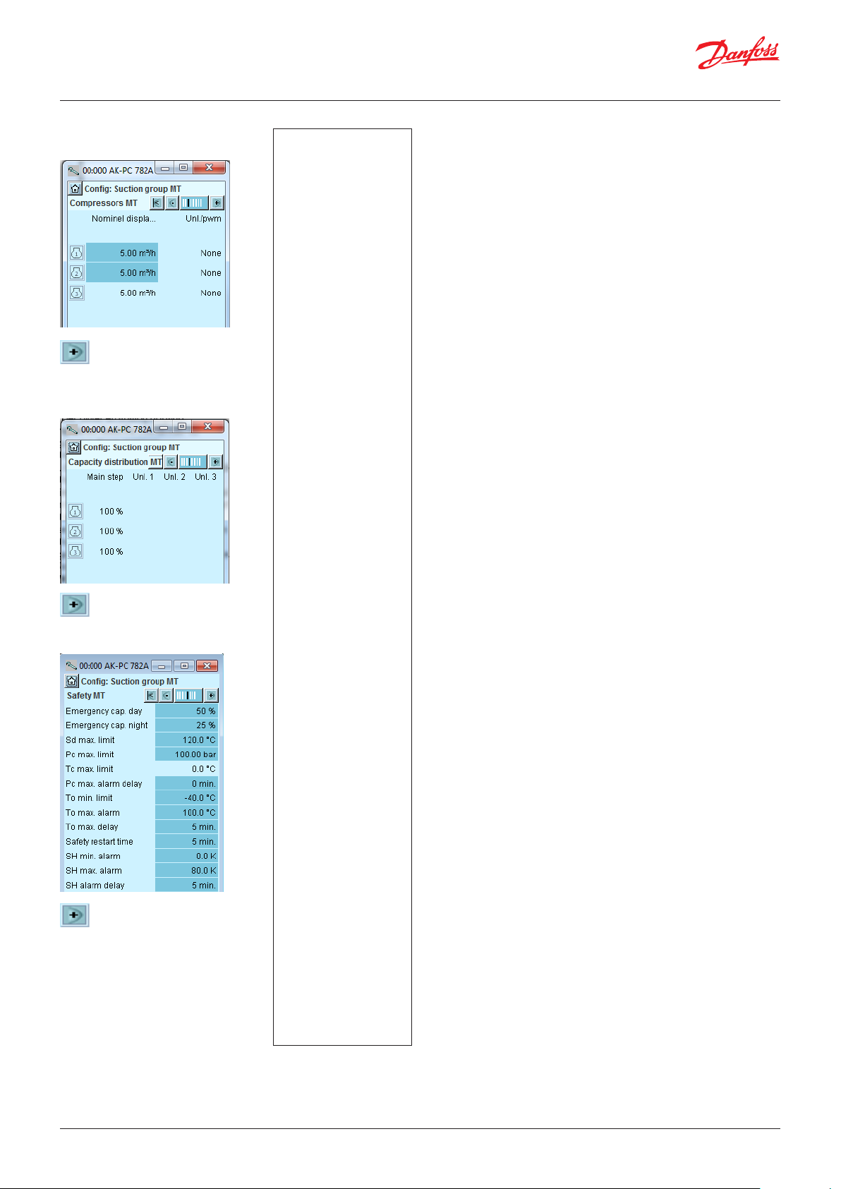
User Guide | Pack controller, type AK-PC 782A
5. Set values for capacity of the
compressors
Press the + button to go to the
next page
6. Set values for main step and any
unloaders
Press the + button to go to the
next page
7. Set values for safe operation
Press the + button to go to the
next page
The compressor capacity
is set in displaced volume
per hour. m3/h.
See compressor data.
In our example there are
no unloaders and hence
no changes.
In our example we select:
- Safety limit for discharge
temperature = 120°C
- Safety limit for high
condensing pressure =
100 bar
- Safety limit for low
suction pressure = -40°C
- Alarm limit for high
suction pressure = -5°C
- Alarm limit for min.
and max. superheat,
respectively = 5 and
35 K.
5 - Compressors
In this screen, the capacity distribution between the compressors
is defined.
Capacities that need to be set depend upon the “compressor
application” and “Step control mode” that has been selected.
Nominal capacity (1 – 1000 m3/h)
Set the nominal capacity for the compressor in question.
For compressors with variable speed drive the nominal capacity
must be set for the mains frequency (50/60 Hz)
Unloader
Number of unload valves for each compressor (0-3)
6 - Capacity distribution
The installation is dependent on the combination of compressors
and coupling pattern
Main step
Set the nominal capacity of the main step (Set the percentage of
the relevant compressor’s nominal capacity) 0 – 100%
Unload
Readout of the capacity on every unloading 0 – 100%
7 - Safety
Emergency cap. day
The desired cut-in capacity for day operation in the case of
emergency operations resulting from error in the suction pressure
sensor/ media temperature sensor
Emergency cap. night
The desired cut-in capacity for night operations in the case of
emergency operations resulting from error in the suction pressure
sensor/ media temperature sensor
Sd max limit
Max. value for discharge gas temperature.
10 K below the limit, the compressor capacity should be reduced
and the entire condenser capacity will be cut in.
If the limit is exceeded, the entire compressor capacity will be cut
out
Pc Max limit
Maximum value for the condenser pressure in bar.
3 K below the limit, the entire condenser capacity will be cut in
and the compressor capacity reduced.
If the limit is exceeded, the entire compressor capacity will be cut out.
Tc max. limit
Limit value read in °C (If selected for display in the condenser
configuration)
Pc Max alarm delay
Time delay for the alarm Pc max.
T0 Min limit
Minimum value for the suction pressure in °C
If the limit is reduced, the entire compressor capacity will be cut out
T0 Max alarm
Alarm limit for high suction pressure P0
T0 Max delay
Time delay before alarm for high suction pressure P0
Safety restart time
Common time delay before restarting the compressor. (Applicable
to the functions: "Sd max. limit", Pc max. limit" and "P0 min. limit)
SH Min alarm
Alarm limit for min. superheat in suction line
SH Max alarm
Alarm limit for max. superheat in suction line
SH alarm delay
Time delay before alarm for min./max. superheat in suction line
© Danfoss | Climate Solutions | 2022.02 BC245386497365en-000801 | 53
Page 54
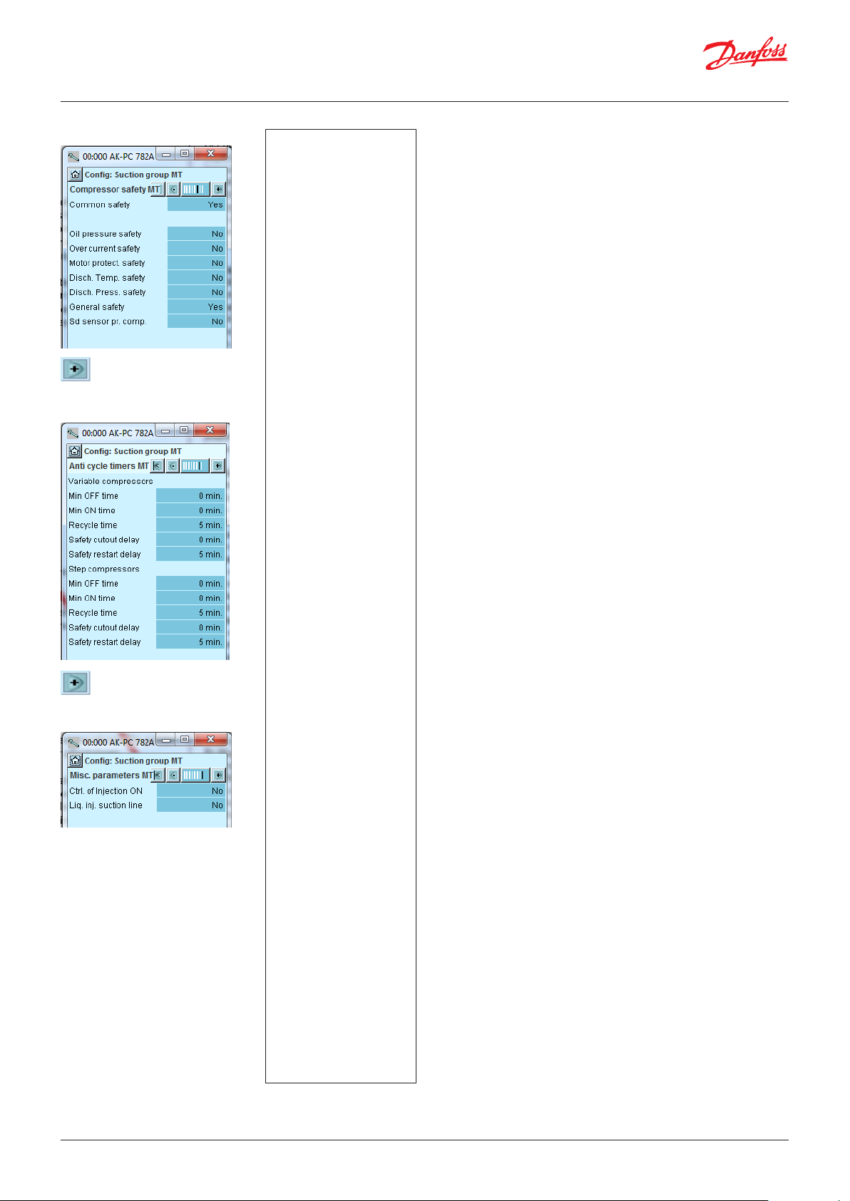
User Guide | Pack controller, type AK-PC 782A
8. Set monitoring of compressor
Press the + button to go to the
next page
9. Set operation time for compressor
Press the + button to go to the
next page
10. Set Misc. functions
In our example we use:
- Common high-pressure
pressure control for all
compressors
- One general safety
monitoring unit for each
compressor
(The remaining options
could have been selected if
specific safety controls for
each compressor had been
required).
Set min. OFF-time for the
compressor relay.
Set min. ON-time for the
compressor relay.
Set how often the
compressor is allowed to
start.
The settings only apply
to the relay that cuts the
compressor motor in and
out.
They do not apply to
unloaders.
If the restrictions overlap,
the controller will use the
longest restriction time.
In our example we do
not use these functions.
8 - Compressor safety
Common safety
Choose whether an overall, common safety input for all
compressors is desired. If the alarm is activated, all compressors
will be cut out.
Oil pressure etc
Define here whether this type of protection should be connected.
For "General" there is a signal from each compressor.
Sd sensor pr. compressor
Select whether an Sd measurement should be made for each
individual compressor
Max discharge temp.
Cut-out temperature.
Sd compressor alarm delay
Delay time for the alarm
Sd compressor safety cutout
Set whether safety cut-out should be enabled
9 - Minimum operation times
Configure the operation times here so "unnecessary operation"
can be avoided.
Recycle time is the time interval between two consecutive starts.
Safety timer
Cutout delay
The time delay resulting from drop-out of automated safety
measures and until the compressor-error is reported. This setting is
common for all safety inputs for the relevant compressor.
Recycle delay
Minimum time before a compressor should be OK after a safety
cut-out. After this interval it can start again.
10 - Misc. functions
Ctrl. of Injection On
DO: Select this function if a relay must be reserved for the function.
(The function must be wired to controllers with expansion valves
in order to close liquid injection for the safety cut-out of the last
compressor.)
Network: The signal is sent to the controllers via data communication.
Compressor start delay
Delay time for compessor start
Injection Off delay
Delay time for "Injection off"
Liq. inj suction line
Select this function if a liquid injection is required in the suction
line in order to keep the discharge gas temperature down.
Regulation can be done either using a solenoid valve and a TEV, or
using an AKV valve.
AKV OD suction line
Readout of opening degree of the valve in %
Inject start SH
Superheat value where the liquid injection starts
Inject diff SH
Differential of superheat for the injection control
Inject start Sd temp.
Start temperature for liquid injection in suction line
Inject diff Sd temp.
Differential when adjusted on Sd
SH Min suction line
Minimum superheat in suction line
SH Max suction line
Maximum superheat in suction line
AKV period time
Periode time for AKV valve
Inject delay at start up
Delay time for liquid injection at start-up
Afterwards, the settings for the LT group and IT group continue.
In principle, the same settings are carried out.
54 | BC245386497365en-000801 © Danfoss | Climate Solutions | 2022.02
Page 55
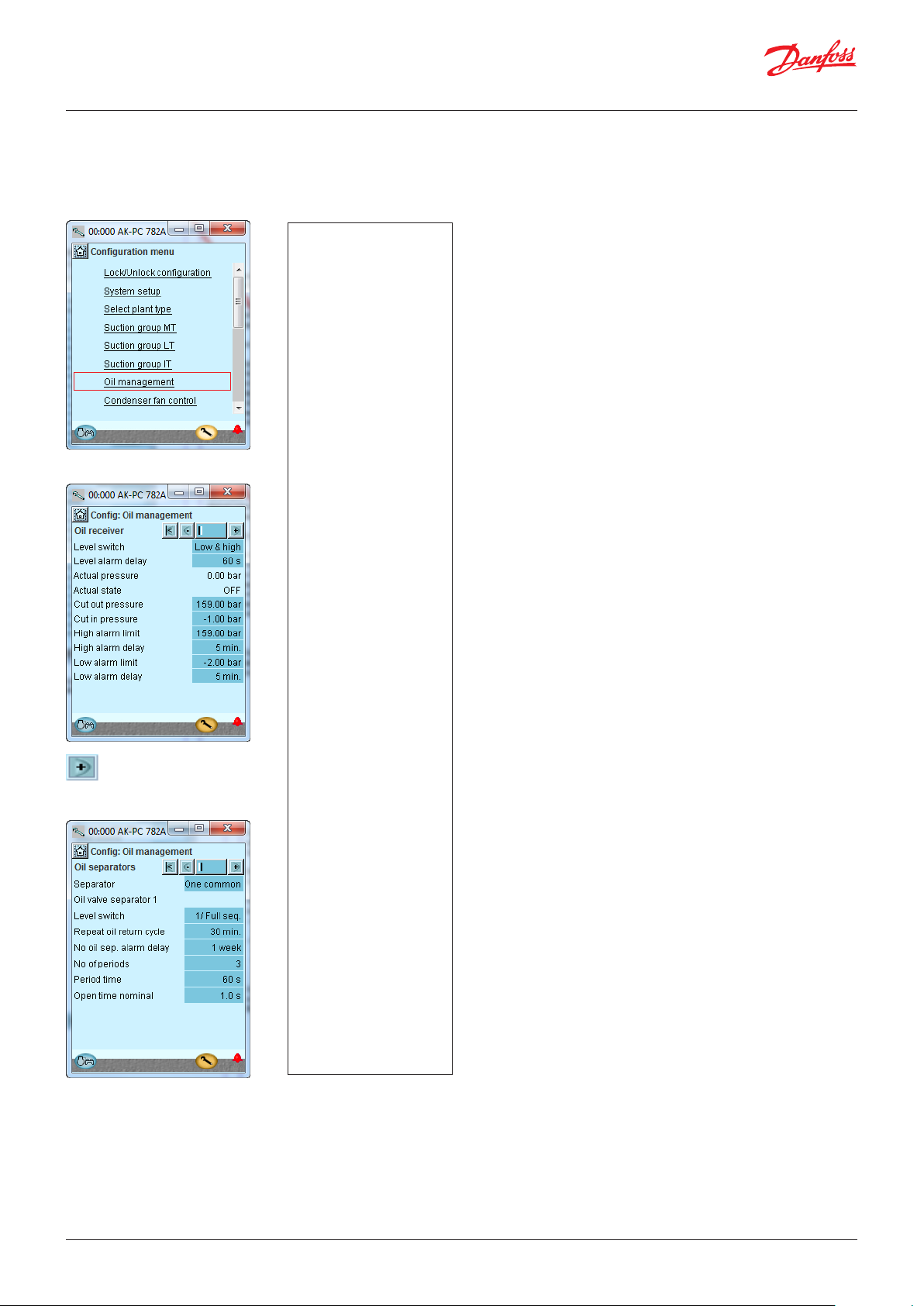
User Guide | Pack controller, type AK-PC 782A
4.1.7 Set oil management
1. Go to Configuration menu
2. Set Oil management
In our example, oil
management has not been
included.
The settings are only
displayed for information
purposes and apply to the
“Fixed pressure” control which
is configured in the "Plant
Type display".
3. Set Oil receiver
In our example, we have two
level switches in the receiver.
Both one high and one low.
3
Level switch receiver
Define the desired level sensors:
High
Both Low and High
Level alarm delay
Delay time for level alarm
Actual pressure
Measured value
Actual state
Status of oil separation
Cut out pressure
Receiver pressure for shutting off oil
Cut in pressure
Receiver pressure for turning on oil
High alarm limit
An alarm is given if a higher pressure is registered
High alarm delay
Time delay for alarm
Low alarm limit
An alarm is given if a lower pressure is registered
Low alarm delay
Time delay for alarm
Press the + button to go to the
next page
4. Set oil separator
The process is as follows:
When a signal is given
from the level switch, the
discharging process to the
receiver commences. This
pulsates three times with
one minute intervals. Each
pulse lasts one second. If the
level switch does not register
an oil drop at this point, an
alarm is given when the delay
time has expired.
4
Separator
Select whether there should be one shared separator for all the
compressors or two separators (MT and IT)
Level detection
Select whether the separator is to be controlled by "Full sequence",
"To Level" or "low and high" level switches
Level alarm delay
Alarm given when using a level switch for low level
Repeat oil return cycle
Time period between repeat emptying processes from the
separator if the level switch stays at high level
No oil sep. alarm delay
Alarm delay when a signal is given that oil is not being separated
("high" level contact not activated).
No of periods
No. of times the valve should open in emptying sequence
Period time
Time between valve openings
Open time
The open time of the valve
© Danfoss | Climate Solutions | 2022.02 BC245386497365en-000801 | 55
Page 56

User Guide | Pack controller, type AK-PC 782A
4.1.8 Set up control of condenser fans
1. Go to Configuration menu
2. Select Condenser fan control
3. Set control mode and reference
Press the + button to go to the
next page
4. Set values for capacity regulation
In our example, the
condenser pressure is
controlled on the basis of the
Sgc and from Sc3 (floating
reference).
The settings shown here in
the display.
In our example we use a
number of fans that are all
speed-controlled in parallel.
The settings are shown here
in the display.
For your information, the
function ”Monitor fan safety”
will require an input signal
from each fan.
3 - Sensor and Reference
Control sensor
Sgc: The temperature at the outlet of the gas cooler
S7: Medium temperature is used for regulation
Reference Mode
Choice of condenser pressure reference:
Fixed setting: Used if a permanent reference is required = “Setting”
Floating: Used if the reference is changed as a function of Sc3 the
external temperature signal, the configured "Dimensioning tm
K"/"Minimum tm K" and the actual cut-in compressor capacity.
(Floating is recommended for CO and heat recovery.)
Setpoint
Setting of desired condensing pressure in temperature
Min. tm
Minimum average temperature difference between Sc3 air and Pc
condensing temperature with no load
Dimensioning tm
Dimensioning average temperature differential between Sc3 air
and Pc condensing temperature at maximum load (tm difference
at max load, typically 2-4 K)
Sgc max reference
Maximum permissible gas cooler outlet temperature. This function
limits the reference for Sgc.
Show Tc
Set whether Tc should be displayed
4 - Capacity control
Capacity control mode
Select control mode for condenser:
Step: Fans are step-connected via relay outputs
Step/speed: The fan capacity is controlled via a combination of
speed control and step coupling
Speed: The fan capacity is controlled via speed control
Speed 1.step: First fan speed controlled, rest step coupling
2 groups with speed: The capacity is divided into groups
No of fans
Set number of fans
(If two groups are selected, this setting is the number in group 1)
Number of fans in group 2
The number in group 2 must be greater than or equal to the
number in group 1
Speed limit for group 1
The speed can be limited to minimize the noise
Monitoring fan safety
Safety monitoring of fans. A digital input is used to monitor each
fan
Fan speed type
VSD (and normal AC motors)
EC motor = DC controlled fan motors
VSD start speed
Minimum speed for start of speed control (must be configured
higher than "VSD Min. Speed")
VSD min Speed
Minimum speed whereby speed control is cut out (low load)
VSD safety monit.
Choice of safety monitoring of frequency converter. A digital inlet
is used for monitoring the frequency converter
EC Start capacity
The regulation awaits this need to arise before supplying voltage
to the EC motor
EC voltage min
Voltage value at minimum capacity (20% = 2 V @ 0 – 10 V)
EC voltage max
Voltage value at 100% capacity (80% = 8 V @ 0 – 10 V)
56 | BC245386497365en-000801 © Danfoss | Climate Solutions | 2022.02
Page 57

User Guide | Pack controller, type AK-PC 782A
EC Voltage abs. max
Permissible live voltage for EC motor (overcapacity)
Absolut max Sgc
Max value for temperature at Sgc. If the value is exceeded, the EC
voltage will be raised to the value in “EC Voltage abs. max.”
Control type
Choice of control strategy
P-band: The fan capacity is regulated via P-band control. The P
band is "100/Kp"
PI-Control: The fan capacity is regulated by the PI controller
Kp
Amplification factor for P/PI controller
Tn
Integration time for PI controller
Capacity limit at night
Setting of maximum capacity limit during night operations. Can be
used to limit fan speed at night in order to limit the noise level
V3gc
Indicates whether a gas by-pass valve is used on the gas cooler.
On/off: Three-way valve controlled by a relay
Step valve: Modulating CTR type three-way valve
Voltage: Three-way valve, e.g. controlled using 0 – 10 V
at on/off:
Bypass low limit - Shp
If the sensor Sgc records a temperature that is lower than the
selected value, the gas will be routed outside of the gas cooler
(e.g. start-up during very low ambient temperatures)
Bypass min. off time
Minimum time during which the gas must be fed through the
gas cooler before bypass is permitted.
At Stepper and Voltage:
Kp
Amplifcation factor for the PI controller.
Tn
Integration time for PI controller.
Min. opening degree
Max. opening degree
© Danfoss | Climate Solutions | 2022.02 BC245386497365en-000801 | 57
Page 58

User Guide | Pack controller, type AK-PC 782A
4.1.9 Set-up of high pressure control
1. Go to Configuration menu
2. Select HP control
3. Set regulation values
Press the + button to go to
the next page
4. Set ejector function
The settings are shown
here in the display
3 - HP control
Vhp output type
Select the signal type for controlling the high pressure valve:
- Voltage signal
- Stepper motor signal via AK-XM 208C
- 2 Stepper motor signals for parallel valves
Extra capacity offset
Adjust how much the pressure shall be increased, when the
function "Extra capacity offset" is activated
Pgc min.
Min. acceptable pressure in the gas cooler
Pgc max.
Max. acceptable pressure in the gas cooler
Advanced settings
Vhp min. OD
Restriction of the valve's closing degree
Pgc max. limit P-band
P-band under "Pgc max" where the valve's opening degree is
increased
dT Subcool
Desired subcooling temperature
Kp
Amplification factor
Tn
Integration time
Pgc HR min.
Read the min. acceptable pressure in the high pressure circuit
during heat recovery
Pgc HR max
Read permissible pressure during heat recovery
Ramp down bar/min.
Here you may select how quickly the reference must be changed
after a completed heat recovery
Temp. at 100 bar
Temperature at 100 bar. Here you may define the regulation curve
during transcritical operation. Set the required temperature value.
4 - Ejector control
Select the Multi Ejector's capacity.
The size will then be shown for each valve’s capacity.
The function is described on page 114-117.
In the next display, the capacity is adjusted for liquid ejectors. The
next display is not visible if liquid ejectors are configured in the
We do not use ejector
control in our example.
previous display.
Warning!
If the regulation is stopped during high-pressure regulation, the
pressure will rise.
The system must be dimensioned to the higher pressure;
otherwise there will be a loss of charge.
58 | BC245386497365en-000801 © Danfoss | Climate Solutions | 2022.02
Page 59

User Guide | Pack controller, type AK-PC 782A
4.1.10 Set up control of receiver pressure
1. Go to Configuration menu
2. Select Receiver control
3. Set parameters for receive reference
3. Receiver reference
Prec ref Mode
Select one of the available reference options for the IT compressor
control:
• "Fixed SP” for a constant reference,
• “Ext. Offset” for a constant reference plus an offset from an
analogue input,
• “IT Optimize” for automatic calculation of the optimum
reference,
• “Delta P” for a constant offset above MT suction pressure
reference (using Delta P reference parameter).
Prec set point / Prec reference
Select the setpoint or display actual reference for the receiver
pressure
Trec set point / Prec reference
Display saturated temperature for Prec setpoint / Prec reference
Prec max.
Max. permissible pressure in the receiver. Exceeding this limit
results in an alarm.
Prec min.
Min. permissible pressure in the receiver. Overpassing this limit
results in an alarm
Enable Delta P min
When enabled, receiver reference is calculated to guarantee
minimum pressure difference with MT suction pressure reference.
Delta P reference
Minimum pressure difference between actual receiver
reference and MT suction pressure reference.
Show Trec on overview
Set whether Trec should be shown in overview display
Ext. Offset max
When the reference mode is “Ext. Offset”, then set the maximum
offset.
Prec min reference / Prec max reference
When the reference mode is “IT optimize” or “Delta P” then set the
minimum and maximum values for receiver reference. Select this
to minimize the floating range of receiver pressure indicating the
amount of gas entering the receiver.
AC support
Enable request signal (DI) and release signal (DO) for air
conditioning AC. When AC is released, the controller is expecting
AC load to contribute to receiver load.
AC Prec min ref / AC Prec max ref
Additional limitation to the pressure range of receiver reference
that only applies when AC is requested via DI. Select the option
to guarantee a maximum and minimum AC temperature.
Receiver inlet min vapour
Maintains a minimum gas pressure in the receiver. The % value
indicates the minimum allowed quality of vapour at receiver inlet.
© Danfoss | Climate Solutions | 2022.02 BC245386497365en-000801 | 59
Page 60

User Guide | Pack controller, type AK-PC 782A
4. Set control parameters
4. Receiver control
Monitor liquid level
Choose whether liquid level should be monitored:
• “Low Level Switch”
• “High Level Switch”
• “High and Low Level Switch”
Liquid alarm delay
Time delay for the alarm
Receiver Valve
The following settings are specific to Vrec receiver valve(s):
Vrec output type
Select the Vrec output type for gas by-pass valve:
• “1 Stepper” for a single stepper motor signal via AK-XM 208C
• “2 Stepper (synchronic)” for two stepper motor signals
operated simultaneously
• “2 Stepper (sequential)” for two stepper motor signals
operated in sequence
• “Voltage (AO)” for a voltage signal
Vrec min. OD
Limitation of the Vrec valve's closing degree
Vrec max. OD
Limitation of the Vrec valve's opening degree
Easy PI selection
Group setting for the control parameters: Kp, Tn. If the setting is
set to “user defined”, the control parameters can be fine-tuned:
Vrec Kp
Amplification factor for PI regulation
Vrec Tn
Integration time for PI regulation
Hot gas dump enable
Select whether hot gas should be supplied if the receiver pressure
falls too low
Hot gas dump cut-in
Receiver pressure at which hot gas is turned on
Hot gas dump delta
Difference at which hot gas is turned off again
60 | BC245386497365en-000801 © Danfoss | Climate Solutions | 2022.02
Page 61

User Guide | Pack controller, type AK-PC 782A
IT Coordination
The following settings are specific for coordinating with suction
group IT:
IT Smart start enable
Enable automatic calculation of “IT Start Vrec OD”, depending
on Vrec valve types, IT size and operating conditions.
IT Start Vrec OD
Opening degree for the Vrec valve when the IT compressor is
to start.
IT Start tuning
Allow the user to modify “IT Start Vrec OD” when “IT Smart
start” is enabled. A value of zero makes the controller aim for
minimum speed of the first IT compressor, a negative value
makes the IT start earlier (lower flow rate) and a higher value
makes the IT start later (higher flow rate).
IT Start delay filter
Time constant for filtering Vrec OD when it is compared against
"IT Start Vrec OD" for starting the IT compressors
IT End delay
The duration that the IT compressor must have been stopped
before regulation is transferred to Vrec.
IT Comp. Sgc min.
The temperature limit for operation with an IT compressor. This
will not start when a lower value is detected, regardless of the
opening degree of the Vrec valve.
Emergency Action
Enable specific control emergency action from other controllers as
a result of too low/high receiver pressure.
Vhp close on high Prec
Enable override of maximum OD for high pressure valve Vhp as
action against high receiver pressure.
Vhp open on low Prec
Enable override of minimum OD for high pressure valve Vhp as
action against low receiver pressure.
MT Cut-on high Prec
Enable to cut off MT compressor capacity as action against high
receiver pressure.
© Danfoss | Climate Solutions | 2022.02 BC245386497365en-000801 | 61
Page 62

User Guide | Pack controller, type AK-PC 782A
4.1.11 Set-up Receiver Reference with Low Pressure
Multi Ejectors
Designed to work with Low
Pressure Multi Ejectors, this
mode is available
when the MT suction control
is configured to alternate
between two pressure
transducers (Po-MT and PsucMT).
Receiver reference is always
calculated as offset from MT
suction reference. It uses
a higher or a lower offset,
determined by a digital input.
The related parameters are
explained to the right.
For information on how to set
these parameters, please see
the application guide: “Low
pressure lift ejector system”
Delta P reference
Display the current pressure difference between the Prec reference
and Po-MT reference.
LP Ej Delta P low
Specify the pressure difference between the Prec reference and
Po-MT reference for the lower Prec reference (DI deactived).
LP Ej Delta P high
Specify the pressure difference between the Prec reference and
Po-MT reference for the higher Prec reference (DI active).
LP Ej Delta P high delay
After deactivating the digital input for the reference "Delta P high",
the parameter “LP Ej Delta P high delay” delays switching back to
the reference "Delta P low" for the specified time.
After activating the digital input, a 30 sec delay is always applied
to switching back to the reference "Delta P high".
62 | BC245386497365en-000801 © Danfoss | Climate Solutions | 2022.02
Page 63

User Guide | Pack controller, type AK-PC 782A
4.1.12 Set up control of heat recovery
1. Go to Configuration menu
2. Select heat circuits
3. Setup values for tap water circuits
4. Setup values for heating circuit
(The heat circuits are
defined in the menu
“Select plant type”)
The menu for domestic
water is empty when
regulation is only carried
out on room heating.
3 - Tap water circuits (settings are available only when there shall
be regulated on a circuit for tap water)
V3tw output type
DO: The valve is controlled by a relay output
Stepper: The valve is controlled by a stepper valve
Control mode: Here the regulation of the circuit can be started
(auto) and stopped (off)
Setpoint: The required temperature for the sensor Stw8 can be set
here
Use ext. ref. offset
A 0 – 10 V signal must displace the temperature reference
Max. Ext. ref. offset
Reference displacement at max. signal (10 V)
Thermostat band: The acceptable temperature variation around
the reference:
Control signal
Choose between:
Stw8: if regulation shall be done using only this sensor
S4-S3: (and a Delta T value) if the controller shall regulate using
this temperature difference, until the Stw8 reference is met.
(During S4-S3 regulation, the pump must always be speedregulated).
Stw8 + Stw8A: if two temperature sensors are installed in the
hot water receiver
Stw4: regulation is done using this sensor
Variable speed: Here the pump type is selected. Either variable
speed or on/off
Advanced settings:
The following options are made available:
Flow switch: Must normally be selected for safety purposes
Kp: Amplification factor
Tn: Integration time
Min. pump speed: Pump speed for start/stop
Max. pump speed: The pump's max. permissible speed
Flowswitch delay: Duration of stable signal before the new status
is used in the regulation
The room heating circuit is
not used in our example.
The image is shown for
information purposes.
The menu for room
heating is empty when
regulation is only carried
out on domestic water.
4 - Heat recovery
V3hr output type
DO: The valve is controlled by a relay output
Stepper: The valve is controlled by a stepper valve
Heat reclaim type for heating
Here you define how the condensing pressure (HP) shall be
regulated when the recovery circuit for heating requires heat:
• No HP offset (simple control)
• HP offset. Here the controller must receive a voltage signal. The
offset values that apply to the max. value must be defined in the
heat circuit settings. See next page.
• Max heat reclaim. Here the controller must receive a voltage
signal, but the regulation is increased to also control pump
activation and deactivation and the by-pass valve.
Control mode: Here the regulation of the circuit can be started
(auto) and stopped (off)
Setpoint: Here the required temperature of sensor Shr8 (or Shr4)
is set
Use ext. ref. offset
A 0-10 V signal must displace the temperature reference
© Danfoss | Climate Solutions | 2022.02 BC245386497365en-000801 | 63
Page 64

User Guide | Pack controller, type AK-PC 782A
Max. Ext. ref. offset
Reference displacement at max. signal (10 V)
Thermostat band: The permissible temperature variation around
the reference:
Control signal: Choose between:
Shr8: if regulation shall be done using only this sensor
S4-S3: (and a Delta T value) if the controller shall regulate using
this temperature difference, until the Shr8 reference has been
met
Shr4: regulation is done using this sensor
(During S4-S3 regulation or Shr4 regulation the pump shall
always be speed regulated)
Variable speed: Here the pump type is selected. Either variable
speed or on/off
Heat consumers: (Only when the condensation pressure shall be
increased during heat recovery). The number of signals that can
be received are set here. The signal can be either 0 – 10 V or 0 – 5 V.
(Settings under "Advanced" will be used 0 – 100% for the signal)
Heat consumer filter
Reduce fast changes in heat consumer signal
Additional heat output
The function will reserve a relay. The relay will energize when the
signal for the heat removers reaches 95%.
Flowswitch delay: Duration of stable signal before the new status
is used in the regulation
Advanced settings: The following options are made available:
Flow switch: Must normally be selected for safety purposes
Kp: Amplification factor
Tn: Integration time
Tc max HR: Value at which the bypass of the gas cooler will
terminate
HR PUMP CONTROL
Min. pump speed: Pump speed for start/stop
Max. pump speed: The pump's max. permissible speed
HR stop limit: Signal in % at which the pump is stopped again
HR start limit: Signal in % at which the pump is started
HP CONTROL
Pgc HR min: Basic reference for the pressure when external
voltage signal is received.
Pgc HR max: Max pressure reference when external voltage
signal is received.
Ref. offset low limit: Signal in % at which "Pgc HR min." comes
into force
Ref.offset high limit: Signal in % at which "Sgc max" value is used
BYPASS CONTROL (at on/off regulation)
V3gc bypass stop limit: Signal in % at which the gas cooler
connects again after completed disconnect
V3gc bypass start limit: Signal in % at which the gas cuts out
64 | BC245386497365en-000801 © Danfoss | Climate Solutions | 2022.02
Page 65

User Guide | Pack controller, type AK-PC 782A
4.1.13 Set up KPI and COP calculation
1. Go to Configuration menu
2. Select KPI setup
In our example, KPI control
is not used. The settings
are included here for
information.
2 - KPI Setup
KPI calculation (KPI = Key Performance Indicator)
If "Yes" is selected, the function will optionally request a signal
from the sensor liquid line (Sliquid temp)
Selected RFG
The system’s refrigerant type is read here
Total swept volume MT
The total swept volume for all of the MT compressors is read here
Total swept volume IT
The total swept volume for all of the IT compressors is read here
Total swept volume LT
The total swept volume for all of the LT compressors is read here
HR active
The system's Heat Recovery state (active or not) is read here
Coldest cabinet MT
Set the desired temperature of the MT circuit’s coldest
refrigeration case
Coldest cabinet LT
Set the desired temperature of the LT circuit’s coldest refrigeration
case
© Danfoss | Climate Solutions | 2022.02 BC245386497365en-000801 | 65
Page 66
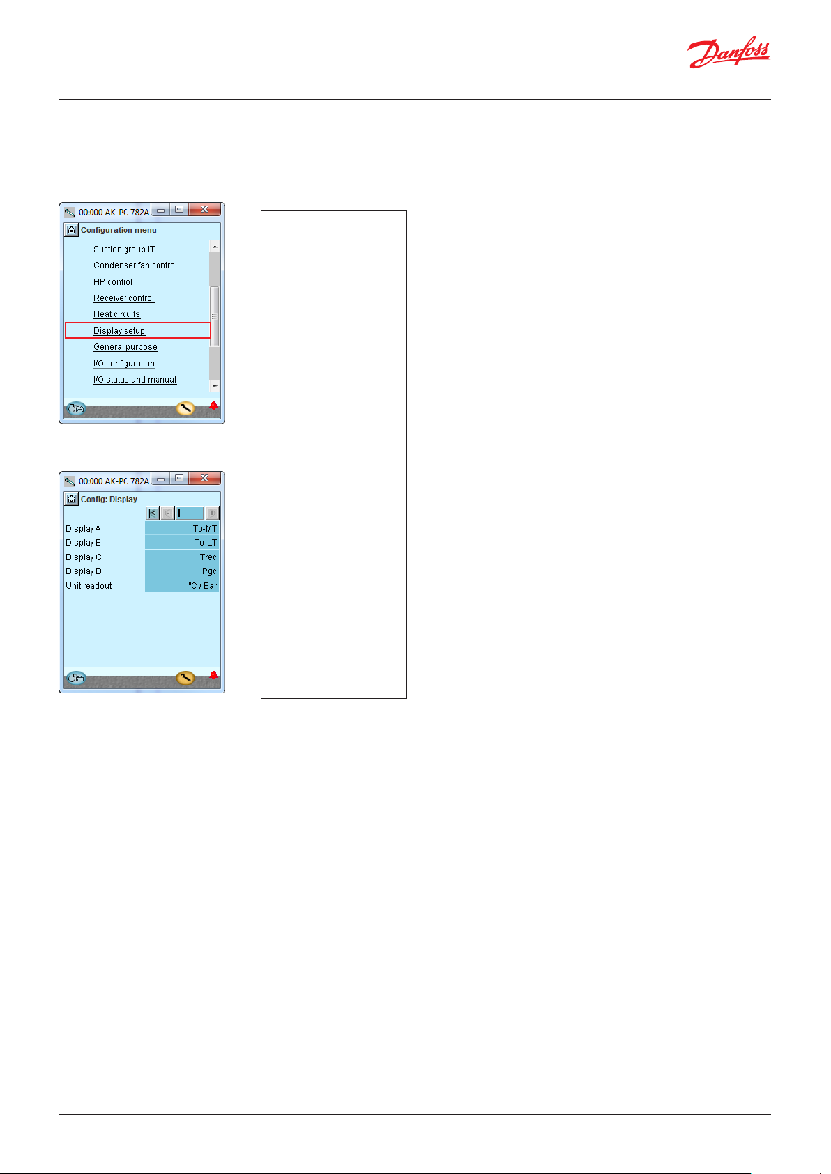
User Guide | Pack controller, type AK-PC 782A
4.1.14 Set up Display
1. Go to Configuration menu
2. Select Display setup
3. Define which readings are to be
shown for the individual outputs
3 - Display set-up
Display
The following can be read for the four outputs:
Comp. control sensor
P0 in temperature
P0 in barSs
Sd
Cond. control sensor
Tc
Pc bar
S7
Sgc
Pgc bar
Prec bar
Trec
Speed Compressor
Unit readout
Choose whether readings are to be in SI units (°C and bar) or (USunits °F and psi)
In our example, separate
displays are not used.
The setting is included
here for information.
66 | BC245386497365en-000801 © Danfoss | Climate Solutions | 2022.02
Page 67
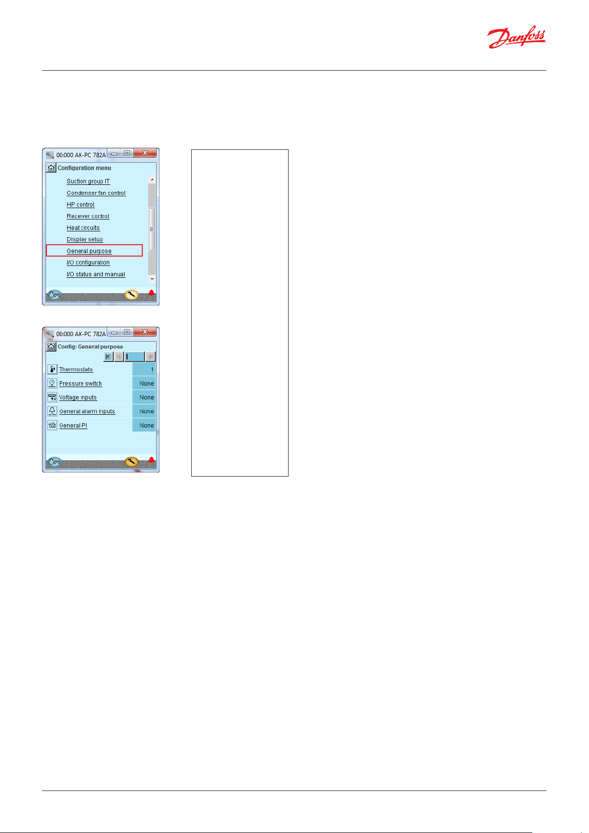
User Guide | Pack controller, type AK-PC 782A
4.1.15 Set-up Functions for General purpose
1. Go to Configuration menu
2. Select General purpose
3. Define number of required functions
In our example we
select one thermostat
function for
temperature control in
the compressor room.
The following number of different functions can be defined:
5 thermostats
5 pressostats
5 voltage signals
10 alarm signals
6 PI-regulations
© Danfoss | Climate Solutions | 2022.02 BC245386497365en-000801 | 67
Page 68

User Guide | Pack controller, type AK-PC 782A
4.1.16 Separate thermostats
1. Select thermostats
2. Select actual thermostat
3. Define the required thermostat
functions
In our example we select
one thermostat function for
monitoring the plant room
temperature.
We have subsequently
entered a name for the
function.
3 - Thermostats
The general thermostats can be used to monitor the temperature
sensors that are used, as well as 4 extra temperature sensors. Each
thermostat has a separate outlet to control external automation.
For each thermostat adjust:
• Whether the thermostat should also be shown in overview
display 1. (The function is always shown in overview display 2)
• Name
• Which of the sensors /(Signal) is used
Actual temp.
Temperature measurement on the sensor that is attached to the
thermostat
Actual state
Actual status on the thermostat outlet
Cut out temp.
Cut-out value for the thermostat
Cut in temp.
Cut-in value for the thermostat
High alarm limit
High alarm limit
Alarm delay high
Time delay for high alarm
Alarm text high
Indicate alarm text for the high alarm
Low alarm limit
Low alarm limit
Alarm delay low
Time delay for low alarm
Alarm text low
Indicate alarm text for low alarm
4.1.17 Separate pressostats
1. Select pressostats
2. Select actual pressostat
3. Define the required pressostat
functions
3 - Pressostats
Settings as the thermostats
In our example, separate
pressostat functions are
not used.
68 | BC245386497365en-000801 © Danfoss | Climate Solutions | 2022.02
Page 69

User Guide | Pack controller, type AK-PC 782A
4.1.18 Separate voltage signals
1. Select Voltage inputs
2. Select actual voltage signal
3. Define the required names and
values attached to the signal
In our example we do not
use this function, so the
display has been included
for your information only.
The name of the function
may be xx and further
down in the display
the alarm texts may be
entered.
The values ”Min. and Max.
Readout” are your settings
representing the lower
and upper values of the
voltage range. 2V and 10V,
for example. (The voltage
range is selected during
the I/O setup).
For each voltage input
defined the controller
will reserve a relay output
in the I/O setup. It is not
necessary to define this
relay if all you require is an
alarm message via the data
communication.
3 - Voltage inputs
The general volt inlet can be used to monitor external voltage
signals. Each volt inlet has a separate outlet to control external
automatic controls.
Set the number of general voltage inputs, specify 1-5:
Show on overview
Name
Select sensor (signal, voltage)
Select the signal which the function should use
Actual value
= readout of the measurement
Actual state
= readout of outlet status
Min. readout
State readout values at minimum voltage signal
Max. readout
State readout values at maximum voltage signal
Cutout
Cut-out value for outlet (scaled value)
Cutin
Cut-in value for outlet (scaled value)
Cutout delay
Time delay for cut-out
Cut in delay
Time delay for cut-in
High alarm limit
High alarm limit
High alarm delay
Time delay for high alarm
High alarm text
Set alarm text for high alarm
Low alarm limit
Low alarm limit
Low alarm delay
Time delay for low alarm
Low alarm text
Indicate alarm text for low alarm
4.1.19 Separate alarm inputs
1. Select General alarm inputs
2. Select actual alarm signal
3. Define the required names and
values attached to the signal
In our example we select
one alarm function for
monitoring the liquid
level in the receiver.
We have subsequently
selected a name for the
alarm function and for
the alarm text.
3 - General alarm input
This function can be used to monitor all kinds of digital signals.
No. of inputs
Set the number of digital alarm inputs
Adjust for each input:
• Show on overview
• Name
• Delay time for DI alarm (common value for all)
• Alarm text
© Danfoss | Climate Solutions | 2022.02 BC245386497365en-000801 | 69
Page 70
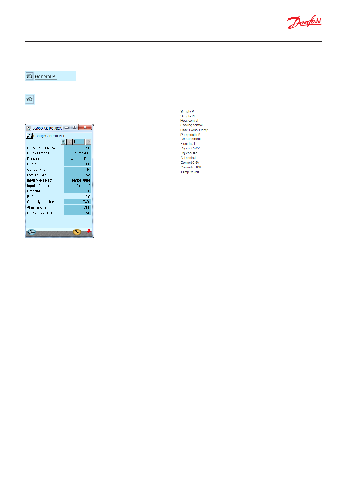
User Guide | Pack controller, type AK-PC 782A
4.1.20 Separate PI functions
1. Select PI functions
2. Select actual PI-function
3. Define the required names and
values attached to the function
3 - General PI Control
The function can be used for optional regulation
Adjust for each regulation:
• Show on overview
• Name
• Quick settings
Here is a list of suggestions for PI regulations:
In our example we do not
use this function, so the
display has been included
for your information only.
• Control mode: Off, Manual or Auto
• Control type: P or PI
• External DI ctrl: Adjusted to "On" if there is an external switch
that can start/stop the regulation.
• Input type: Choose which signal the regulation shall receive:
Temperature, pressure, pressure converted to temperature,
voltage signal, Tc, Pc, Ss, Sd etc.
• Reference: Either fixed or signal for the variable reference:
Choose between: : Non, temperature, pressure, pressure
converted to temperature, voltage signal, Tc, Pc, Ss, DI etc.
• Setpoint: If fixed reference is chosen
• Reading the total reference
• Output: Here you select the outlet function (PWM = pulse width
modulated (e.g. AKV valve)), Stepper signal for a stepper motor
or voltage signal
• Alarm mode: Choose whether an alarm shall be attached to the
function. If it is set to "On", alarm texts and alarm limits can be
entered
• Advanced ctrl. settings:
– Ref. X1, Y1 and X2,Y2: Points that define and limit the variable
reference
– PWM period time: Period during which the signal has been on
and off.
– Kp: Amplification factor
– Tn: Integration time
– Filter for reference: Duration for smooth changes to the
reference
– Max. error: Maximum permissible fault signal at which the
integrator remains in the regulation
– Min. control output: Lowest permitted output signal
– Max. control output: Maximum permitted output signal
– Start-up time: Time at start-up at which the output signal is
force-controlled
– Start-up output: The output signal size at the start-up time.
– Stop output signal. Size of the output signal when regulation
is off
70 | BC245386497365en-000801 © Danfoss | Climate Solutions | 2022.02
Page 71

User Guide | Pack controller, type AK-PC 782A
4.1.21 Configuration of inputs and outputs
1. Go to Configuration menu
2. Select I/O configuration
3. Configuration of Digital outputs
Press the + button to go to
the next page
4. Set up On/off inputs
Press the + button to go to
the next page.
The following displays will depend on the earlier
definitions. The displays will show which connections the
earlier settings will require. The tables are the same as
shown earlier.
• Digital outputs
• Digital inputs
• Analogue outputs
• Analogue inputs
Load Output Module Point Active at
Hot gas dump DO1 1 12 ON
Circulation pump tw DO2 1 13 ON
MT Compressor 1 (VLT start) DO5 1 16 ON
MT Compressor 2 D06 1 17 ON
MT Compressor 3 DO7 1 18 ON
IT Compressor (VLT start) DO8 1 19 ON
LT Compressor 1 (VLT start) DO1 4 9 ON
LT Compressor 2 DO2 4 10 ON
Fan motors (VLT start) DO3 4 11 ON
3-way valve, tap water, Vtw DO5 4 13 ON
Room fan DO7 4 15 ON
We set up the controller’s digital outputs by keying in which
module and point on this module each one of these has been
connected to.
We furthermore select for each output whether the load is to be
active when the output is in pos. ON or OFF.
Attention! Relay outputs must not be inverted at unloader
valves. The controller inverts the function itself.
There will be no voltage at the by-pass valves when the
compressor is not in operation. Power is connected immediately
before the compressor is started.
Function Input Module Point Active at
Level switch, CO2 receiver AI2 2 2 Open
Start/stop of heat recovery tw AI3 2 3 Closed
MT Compressor 1 Gen. Safety AI1 3 1 Open
MT Compressor 2 Gen. Safety AI2 3 2 Open
MT Compressor 3 Gen. Safety AI3 3 3 Open
IT Compressor Gen. Safety AI4 3 4 Open
LT Compressor 1 Gen. Safety AI5 3 5 Open
LT Compressor 2 Gen. Safety AI6 3 6 Open
External main switch AI3 4 3 Closed
MT compressors common
safety
LT compressors common safety AI6 4 6 Open
We set up the controller’s digital input functions by keying in
which module and point on this module each one of these has
been connected to.
We furthermore select for each output whether the function is to
be active when the output is in pos. Closed or Open.
Open has been selected here for all the safety circuits. This means
that the controller will receive signal under normal operation and
register it as a fault if the signal is interrupted.
AI4 4 4 Open
3 - Outputs
The possible functions are the
following:
Comp. 1
Unloader 1-1
Unloader 1-2
Unloader 1-3
Do for Compressor. 2-8
Oil valve comp. 1-2
Injection suction line
Injection ON
Fan 1 / VSD
Fan 2 - 8
HP Control
Ejector
Valve gas cooler V3gc
Hot gas Dump
Heat recovery
Valve tap water V3tw
Pump tap water tw
Valve heat recov. V3hr
Pump heat recov. hr
Additional heat
Alarm
I'm alive relay
Thermostat 1 - 5
Pressostat 1 - 5
Volt input 1 - 5
PI 1-3 PWM
4 - Digital inputs
The possible functions are the
following:
Ext. Main switch
Ext. compr. stop
Ext. power loss
Night setback
Load shed 1
Load shed 2
All compressors:
Common safety
Comp. 1
Oil pressure safety
Over current safety
Motor protect. safety
Disch. temp. safety
Disch. press. safety
General safety
VSD comp. Fault
Do for Comp. 2-8
Fan 1 safety
Do for fan 2-8
VSD cond safety
Oil receiver low
Oil receiver high
Oil separator low 1-2
Oil separator high 1-2
AC limit
Rec. low liquid level
Rec. high liquid level
Heat recovery
tw enable
hr enable
Flow switch tw
Flow switch hr
DI 1 Alarm input
DI 2-10 ...
PI-1 Di ref
External DI PI-1
© Danfoss | Climate Solutions | 2022.02 BC245386497365en-000801 | 71
Page 72
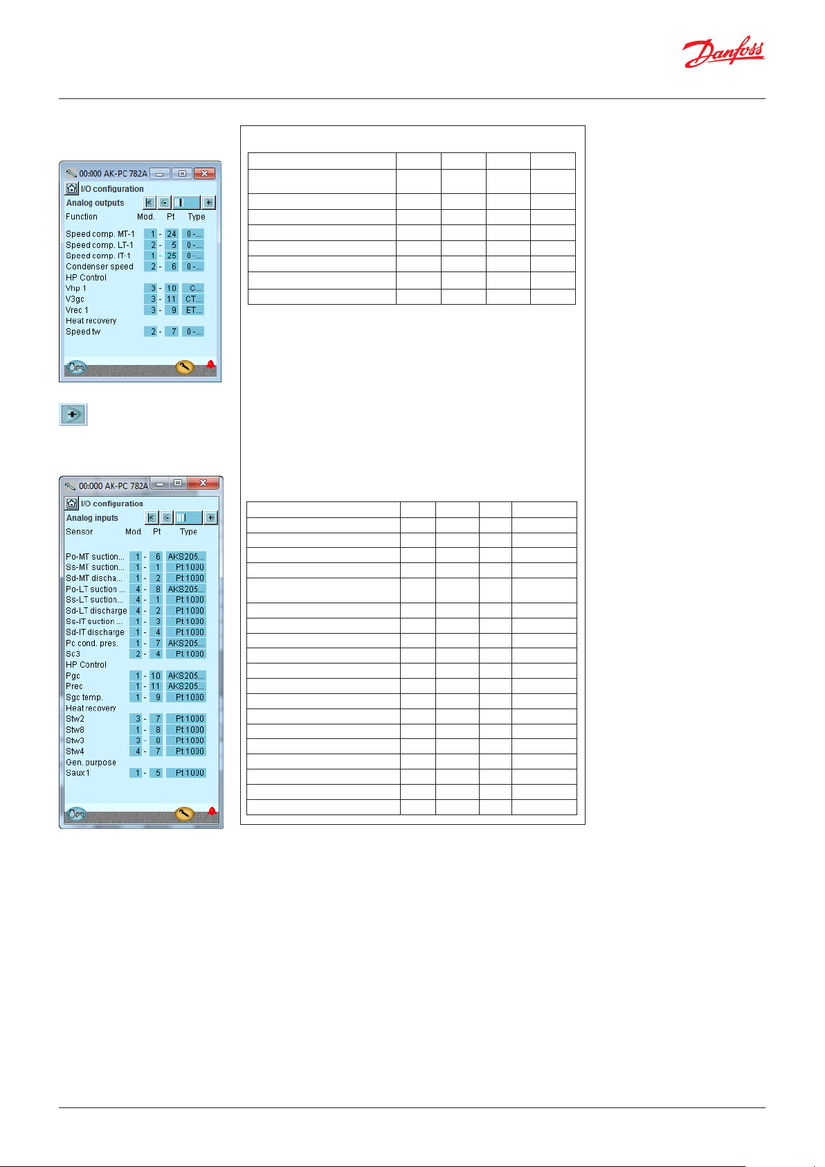
User Guide | Pack controller, type AK-PC 782A
5. Configuration of Analogue
outputs
Press the + button to go
to the next page
6. Configuration of Analogue Input
signals
Function Output Module Point Type
Speed control, MT compressor AO1 1 24 0 – 10 V
Speed control, IT compressor AO2 1 25 0 – 10 V
Speed control, LT compressor AO1 2 5 0 – 10 V
Speed control, fan gas cooler AO2 2 6 0 – 10 V
Speed control, pump tw AO3 2 7 0 – 10 V
Signal to by-pass ventil, Vrec Step 1 3 9 CCMT
Signal to high pressure valve, Vhp Step 2 3 10 CCMT
3-way valve, gas cooler, V3gc Step 3 3 11 CTR
Sensor Input Module Point Type
Discharge gas temperature - Sd-MT AI1 1 1 Pt 1000
Suction gas temperature - Ss-MT AI2 1 2 Pt 1000
Discharge gas temperature - Sd-IT AI3 1 3 Pt 1000
Suction gas temperature - Ss-IT AI4 1 4 Pt 1000
Thermostat sensor in plant room
- Saux1
Suction pressure - P0-MT AI6 1 6 AKS 2050-59
Condenser pressure - Pc-MT AI7 1 7 AKS 2050-159
Tap water temperature - Stw8 AI8 1 8 Pt 1000
Temp. gas cooler outlet Sgc AI9 1 9 Pt 1000
Gas cooler pressure Pgc AI10 1 10 AKS 2050-159
Refrigerant receiver, Prec CO
Temp. by-passed gas Shp AI1 2 1 Pt 1000
Outdoor temp, Sc3 AI4 2 4 Pt 1000
Heat recovery tw2 AI7 3 7 Pt 1000
Heat recovery tw3 AI8 3 8 Pt 1000
Discharge gas temperature - Sd-LT AI1 4 1 Pt 1000
Suction gas temperature - Ss-LT AI2 4 2 Pt 1000
Heat recovery tw4 AI7 4 7 Pt 1000
Suction pressure - P0-LT AI8 4 8 AKS 2050-59
AI5 1 5 Pt 1000
AI11 1 11 AKS 2050-159
2
5 - Analogue outputs
The possible signals are the
following:
0 – 10 V
2 – 10 V
0 – 5 V
1 – 5 V
10 – 0 V
5 – 0 V
Stepper output
Stepper output 2
Stepper user defined and Valve setup: see section "Miscellaneous"
6 - Analogue inputs
The possible signals are the
following:
Temperature sensors:
• Pt1000
• PTC 1000
Pressure transmitters:
• AKS 32, -1 – 6 bar
• AKS 32R, -1 – 6 bar
• AKS 32, - 1 – 9 bar
• AKS 32R, -1 – 9 bar
• AKS 32, - 1 – 12 bar
• AKS 32R, -1 – 12 bar
• AKS 32, - 1 – 20 bar
• AKS 32R, -1 – 20 bar
• AKS 32, - 1 – 34 bar
• AKS 32R, -1 – 34 bar
• AKS 32, - 1 – 50 bar
• AKS 32R, -1 – 50 bar
• AKS 2050, -1 – 59 bar
• AKS 2050, -1 – 99 bar
• AKS 2050, -1 – 159 bar
• MBS 8250, -1 – 159 bar
• User defined (ratiometric 10 – 90%
of 5 V supply). Min. and max. value
of the sensor range must be set in
relative pressure.
Po suction pres.
Ss suction gas
Sd disch. temp.
Pc Cond. Pres.
S7 Warm brine
Sc3 air on
Ext. Ref. Signal
• 0 – 5 V,
• 0 – 10 V
Oil receiver
HP control
Pgc
Prec
Sgc
Shp
Stw2,3,4,8
Shr2,3,4,8
HC 1-5
Heat recovery
Saux 1 - 4
Paux 1 - 3
Voltage input 1 - 5
• 0 – 5 V,
• 0 – 10 V,
• 1 – 5 V,
• 2 – 10 V
PI-in temp
PI-ref temp
PI- in voltage
PI-in pres.
PI-ref pres.
72 | BC245386497365en-000801 © Danfoss | Climate Solutions | 2022.02
Page 73

User Guide | Pack controller, type AK-PC 782A
4.1.22 Set alarm priorities
1. Go to Configuration menu
2. Select Alarm priorities
Many functions have an alarm connected.
Your choice of functions and settings has connected all the
relevant alarms that are current. They will be shown with text
in the three pictures.
All alarms that can occur can be set for a given order of
priority:
• ”High” is the most important one
• ”Log only” has lowest priority
• ”Disconnected” gives no action
The interdependence between setting and action can be seen
in the table.
3. Set priorities for Suction group
Setting
High X X X X 1
Medium X X X 2
Low X X X 3
Log only
Disconnected
Log Alarm relay selection Net-
Non High Low - High
X 4
work
See also alarm text page 131.
AKM dest.
Press the + button to go to the next page
4. Set alarm priorities for condenser
In our example we select the settings shown here in the
display.
Press the + button to go to the next page
© Danfoss | Climate Solutions | 2022.02 BC245386497365en-000801 | 73
Page 74

User Guide | Pack controller, type AK-PC 782A
5. Set alarm priorities for thermostat and extra digital signals
4.1.23 Lock configuration
1. Go to Configuration menu
2. Select Lock/Unlock configuration
In our example we select the settings shown here in the
display.
3. Lock Configuration
The controller will now make a comparison of selected functions
and define inputs and outputs. The result can be seen in the next
section where the set-up is controlled.
Press the field Configuration lock.
Select Locked.
The set-up of the controller has now been locked. If you
subsequently want to make any changes in the controller’s
set-up, remember to unlock the configuration first.
74 | BC245386497365en-000801 © Danfoss | Climate Solutions | 2022.02
Page 75

User Guide | Pack controller, type AK-PC 782A
4.1.24 Check configuration
1. Go to Configuration menu
2. Select I/O configuration
3. Check configuration of Digital Outputs
This control requires that the set-up is locked.
(Only when the set-up is locked, are all settings for in- and outputs activated).
An error has occurred, if you see the
following:
The set-up of the digital
outputs appears as it is
supposed to according
to the wiring made.
A 0 – 0 next to a defined function.
If a setting has reverted to 0-0, you must
control the set-up again.
This may be due to the following:
• A selection has been made of a
combination of module number and
point number that does not exist
• The selected point number on the
selected module has been set up for
something different
The error is corrected by setting up the
output correctly.
Remember that the set-up must be unlocked
before you can change module and point
numbers.
Press the + button to go to the next page
4. Check configuration of Digital Inputs
Press the + button to go to the next page
The set-up of the digital
inputs appears as it is
supposed to according
to the wiring made.
The settings are shown on a RED
background.
If a setting has turned red, you must control
the set-up again.
This may be due to the following:
• The input or the output has been set up;
but the set-up has later been changed so
that it should no longer be applied.
The problem is corrected by setting
module number to 0 and point number
to 0.
Remember that the set-up must be
unlocked before you can change module
and point numbers.
© Danfoss | Climate Solutions | 2022.02 BC245386497365en-000801 | 75
Page 76
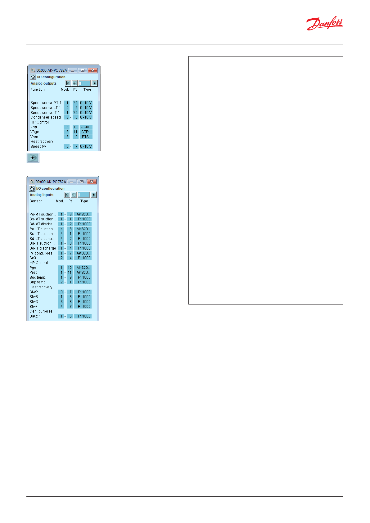
User Guide | Pack controller, type AK-PC 782A
5. Check configuration of Analogue Outputs
Press the + button to go to the next page
6. Check configuration of Analogue Inputs
The set-up of the analogue outputs appears as it is supposed to
according to the wiring made.
The set-up of the analogue inputs appears as it is supposed to
according to the wiring made.
76 | BC245386497365en-000801 © Danfoss | Climate Solutions | 2022.02
Page 77

User Guide | Pack controller, type AK-PC 782A
4.2 Check of connections
1. Go to Configuration menu
2. Select I/O status and manual
3. Check Digital Outputs
Press the + button to go to the next page
Before the control is started, we check that all inputs and
outputs have been connected as expected.
This control requires that the set-up is locked.
By means of the manual control of each output it can be
checked whether the output has been correctly connected.
AUTO The output is controlled by the controller
MAN OFF The output is forced to pos. OFF
MAN ON The output is forced to pos ON
4. Check Digital Inputs
Press the + button to go to the next page
Cut out the safety circuit for compressor 1.
Check that LED DI1 on the extension module (module 2) goes
out.
Check that the value of the alarm for the safety monitoring of
compressor 1 changes to ON.
The remaining digital inputs are checked in the same way.
© Danfoss | Climate Solutions | 2022.02 BC245386497365en-000801 | 77
Page 78

User Guide | Pack controller, type AK-PC 782A
5. Check Analogue outputs
6. Put the control of the output voltage back to automatic
Set Control of output voltage to manual
Press in the Mode field.
Select MAN.
Press in the Value field
Select for example 50%.
Press OK.
On the output you can now measure the expected value: In
this example 5 volts
Example of the connection between a defined
output signal and a manual set value.
Definition Setting
0 % 50 % 100 %
0 - 10 V 0 V 5 V 10 V
1 - 10 V 1 V 5.5 V 10 V
0 - 5 V 0 V 2.5 V 5 V
2 - 5 V 2 V 3.5 V 5 V
10 - 0 V 10 V 5 V 0 V
5 - 0 V 5 V 2,5 V 0 V
Press the + button to go to the next page
7. Check Analogue inputs
Check that all sensors show sensible values.
In our case we have no values. This may be due to the
following:
• The sensor has not been connected.
• The sensor is short-circuited.
• The point or module number has not been set up correctly.
• The configuration is not locked.
78 | BC245386497365en-000801 © Danfoss | Climate Solutions | 2022.02
Page 79

User Guide | Pack controller, type AK-PC 782A
4.3 Check of settings
1. Go to the overview
Before the control starts, we check that all the settings are as
they should be.
The overview display will now show one line for each of the
general functions. Behind each icon there is a number of
displays with the different settings. All these settings have to
be checked.
2. Select suction group
3. Move on through all the individual displays for the suction group
Change displays with the + button. Remember the settings at
the bottom of the pages – the ones that can only be seen via the
”Scroll bar”.
4. Check the individual pages
The last page contains control data.
5. Go back to the overview. Repeat for IT and LT
6. Select condenser group
© Danfoss | Climate Solutions | 2022.02 BC245386497365en-000801 | 79
Page 80

User Guide | Pack controller, type AK-PC 782A
7. Move on through all the individual displays for the condenser
group.
Change displays with the + button. Remember the settings at
the bottom of the pages – the ones that can only be seen via the
”Scroll bar”.
8. Check the individual pages
The last page contains reference settings.
9. Go back to the overview and move on to the rest of the functions
10. General functions
When all the functions in overview display 1 have been reviewed,
it is time to look at the "General functions" in overview display 2.
Press the + button to access.
The first is the thermostat group
Check the settings.
11. Then the pressure switch group
Check the settings.
12. Proceed with the remaining functions
13. The controller set-up has been completed
All the defined general functions are shown in overview display
2.
In addition to always being shown in display 2, functions can
be selected to be shown in display 1. Individual functions can
be selected for display in display 1 via the "Show in overview
display" setting.
80 | BC245386497365en-000801 © Danfoss | Climate Solutions | 2022.02
Page 81

User Guide | Pack controller, type AK-PC 782A
4.4 Schedule function
1. Go to Configuration menu
2. Select schedule
3. Set up schedule
Before regulation is started, we will set the schedule function
for the night setback of the suction pressure.
In other cases where the controller is installed in a network
with one system unit, this setting may be made in the system
unit which will then transmit a day/night signal to the
controller.
Press a day of the week and set the time for the day period.
Continue with the other days.
A complete weekly sequence is shown in the display.
© Danfoss | Climate Solutions | 2022.02 BC245386497365en-000801 | 81
Page 82
User Guide | Pack controller, type AK-PC 782A
4.5 Installation in network
1. Set the address (here, for example 3)
Turn the right-hand address switch so that the arrow will point
at 3.
The arrow of the two other address switches must point at 0.
2. Push the Service Pin
Press down the Service Pin and keep it down until the Service
Pin LED lights up.
3. Wait for answer from the system unit
Depending on the size of the network it may take up to one
minute before the controller receives an answer as to whether
it has been installed in the network.
When it has been installed, the Status LED will start to flash
faster than normal (once every half second). It will continue
with this for about 10 minutes.
4. Carry out new login via Service Tool
If the Service Tool was connected to the controller while you
installed it in the network, you must carry out a new login to
the controller via the Service Tool.
The controller has to be remote-monitored via a network. In
this network we assign address number 3 to the controller.
The same address must not be used by more than one
controller in the same network.
Requirement to the system unit
The system unit must be:
- AK-SM 720.
- AK-SM 800 serie.
If there is no answer from the system unit:
If the Status LED does not start flashing faster than normal, the
controller has not been installed in the network. The reason
for this may be one of the following:
The controller has been assigned an address out of range
Address 0 cannot be used.
The selected address is already being used by another
controller or unit in the network:
The address setting must be changed to another (vacant)
address.
The wiring has not been carried out correctly.
The termination has not been carried out correctly.
The data communication requirements are described in the
document: ”Data communication connections to ADAPKOOL® Refrigeration Controls” RC8AC.
82 | BC245386497365en-000801 © Danfoss | Climate Solutions | 2022.02
Page 83

User Guide | Pack controller, type AK-PC 782A
4.6 First start of control
Check alarms
1. Go to the overview
Press the blue overview button with the compressor and
condenser at the bottom left of the display.
2. Go to the Alarm list
Press the blue button with the alarm bell at the bottom of the
display.
3. Check active alarms
4. Remove cancelled alarm from the alarm list
Press the red cross to remove cancelled alarms from the alarm list.
5. Check active alarm again
In our case, we have a series of alarms. We will tidy them up
so that we only have those that are relevant.
In our case an active alarm remains because the control has
stopped.
This alarm must be active when control has not started. We
are now ready for the start-up of control.
Please note that active plant alarms are automatically
cancelled when the main switch is in pos. OFF.
If active alarms appear when the control is started, the reason
for these should be found and remedied.
© Danfoss | Climate Solutions | 2022.02 BC245386497365en-000801 | 83
Page 84

User Guide | Pack controller, type AK-PC 782A
4.6.1 Start the control
1. Go to Start/Stop display
Press the blue manual control button at the bottom of the display.
2. Start control
Press in the field against Main switch.
Select ON.
The controller will now start controlling the compressors and
the fans.
Note:
Control does not start until both the internal and external
switches are “ON”.
Any external compressor stop breaker must be "ON" for the
compressors to start.
84 | BC245386497365en-000801 © Danfoss | Climate Solutions | 2022.02
Page 85

User Guide | Pack controller, type AK-PC 782A
4.6.2 Manual capacity control
1. Go to overview
2. Select suction group
Press the suction group button for the suction group that is to be
controlled manually.
Press the + button to go to the next page
3. Set capacity control to manual
If you need to manually adjust the capacity of the compressors,
you can use the following procedure:
4. Set capacity in percentage
Press in the blue field Manual capacity.
Press the blue field Control mode.
Select MAN.
Set the capacity to the required percentage.
Press OK.
© Danfoss | Climate Solutions | 2022.02 BC245386497365en-000801 | 85
Page 86
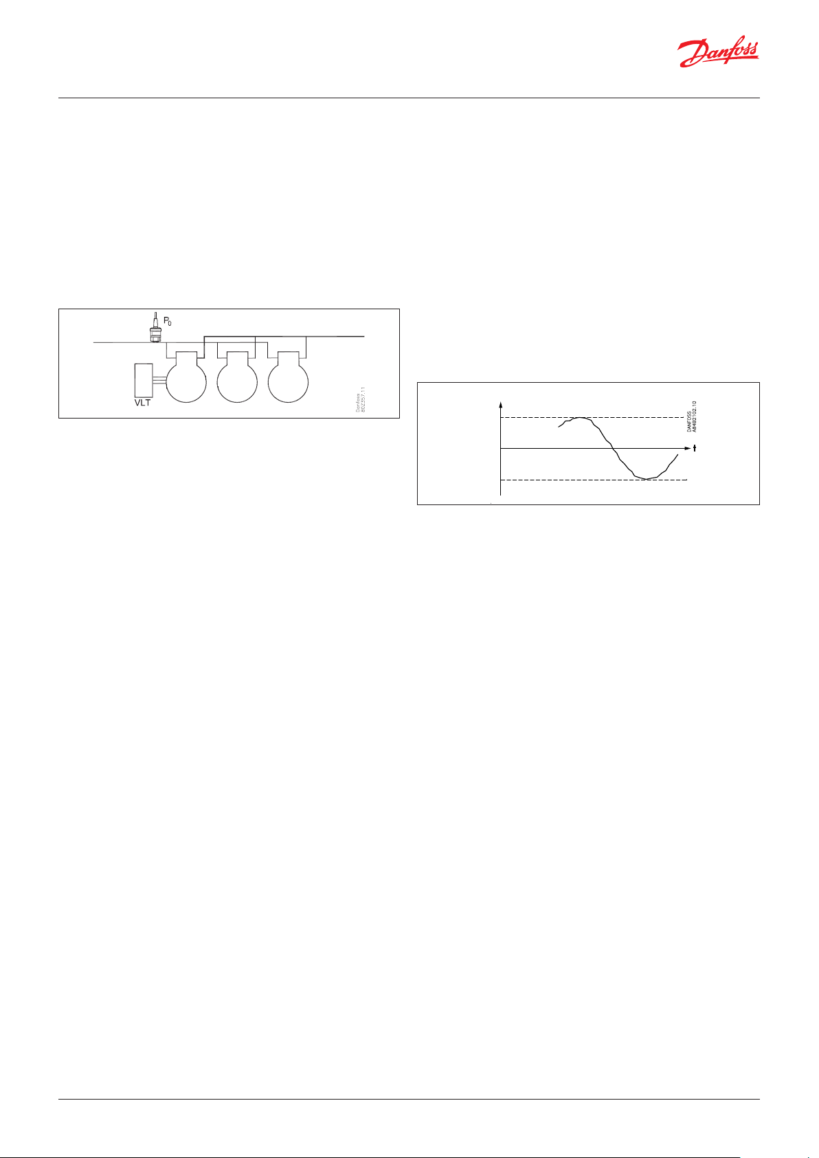
User Guide | Pack controller, type AK-PC 782A
5. Regulating functions
This section describes how the different functions work.
5.1 Suction group
Controlling sensor
The capacity distributor can regulate according to the suction
pressure P0.
The IT compressors are also regulated according to the suction
pressure, but the signal is received from the receiver - Prec. See
page 118 for IT description
An error in the controlling sensor will mean that regulation
continues with fx. 50% cut-in in daily operation and e.g. 25% cut-in
at night, but for a minimum of one step.
Reference
The reference for the regulation can be defined in 2 ways:
Either
P0Ref = P0 setting + P0 optimization + night displacement
or
P0Ref = P0 setting + Ext. Ref + night displacement
P0 setting
A basic value for the suction pressure is set.
P0 optimization
This function displaces the reference so that regulation will not
take place with a lower suction pressure than required.
The function cooperates with controllers on the individual
refrigeration appliances and a system manager. The system
manager obtains data from the individual regulations and adapts
the suction pressure to the optimum energy level. The function is
described in the manual for the system manager.
With this function you can read which appliance is most heavily
loaded at the moment as well as the displacement allowed for the
suction pressure reference.
Night displacement
The function is used to change the suction pressure reference for
night time operation as an energy saving function.
With this function the reference can be displaced by up to 25 K
in positive or negative direction. (When you displace to a higher
suction pressure, a positive value is set).
Displacement can be activated in three ways:
• Signal on an input
• From a system unit override function
• Internal time schedule
If a short change in the suction pressure is needed (for example,
up to 15 minutes in connection with defrosting), the functions
can be applied. Here the PO-optimisation will not have time to
compensate for the change.
Override with a 0 - 10 V signal
When a voltage signal is connected to the controller, the
reference can be displaced. In the set-up it is defined how big
a displacement is to take place at max. signal (10 V) and at min.
signal.
Limitation of reference
To safeguard yourself against a too high or too low regulation
reference, a limitation of the reference must be set.
P0 ref
Max.
Min.
Forced operation of the compressor capacity in the suction
group
A forced operation of the capacity can be carried out which
disregards the normal regulation.
Depending on the selected form of forced operation, the safety
functions will be cancelled.
Forced operation via overload of requested capacity
The control is set to manual and the desired capacity is set in % of
the possible compressor capacity.
Forced operation via overload of digital outlets
The individual outputs can be set to MAN ON or MAN OFF in the
software. The control function disregards this, but an alarm is sent
out that the outlet is being overridden.
Forced operation via change-over switches
If the forced operation is done with the switch-over on the front of
an expansion model, this is not registered by the control function
and no alarm is sounded. The controller continues to run and
couples with the other relays.
Coordination between the LT and MT compressors
The LT (low pressure) compressors are only permitted to start
when MT (medium pressure) is ready, but has not necessarily
started the compressors.
LT will then start when required.
When this happens, MT will register the pressure increase and
immediately start the MT compressors in line with the desired
pressure.
The “night displacement” function should not be used when
regulation with the override function “P0-optimisation” is performed.
(Here the override function itself will adapt the suction pressure to the
max. permissible).
86 | BC245386497365en-000801 © Danfoss | Climate Solutions | 2022.02
Page 87

User Guide | Pack controller, type AK-PC 782A
Time
Requested
5.2 Capacity control of compressors
Capacity control
AK-PC 782A can control 3 compressor groups - MT, IT and LT.
Each compressor can have up to 3 unloaders. One or two of the
compressors can be equipped with speed regulation.
The cut-in capacity is controlled by signals from the connected
pressure transmitter and the set reference.
Set a neutral zone around the reference .
In the neutral zone, the regulating compressor controls the
capacity so that pressure can be maintained. When it can no
longer maintain the pressure within the neutral zone, the
controller will cut out or cut in the next compressor in the
sequence.
When further capacity is either cut out or cut in, the capacity
from the regulating compressor will be modified accordingly
to maintain the pressure within the neutral zone (only where
the compressor has variable capacity).
• When the pressure is higher than the “reference + a half neutral
zone”, cut-in of the next compressor (arrow up) is permitted.
• When the pressure is lower than the “reference - a half neutral
zone”, cut-out of a compressor (arrow down) is permitted.
• When the pressure is within the neutral zone, the process
will continue with the currently activated compressors. Unload
valves (if present) will activate, depending on whether suction
pressure is above or below the reference value.
Suction pressure P0
Example:
4 compressors of equal size - The capacity curve will look like this
capacity %
C4
C3 C3 C3
C2
C2 C2 C2 C2
C1 C1 C1 C1 C1 C1 C1
Cut-out of the last compressor stage:
Normally, the last compressor step will only be cut out when the
required capacity is 0% and the suction pressure is below the
neutral zone.
Operation time first step
At start-up the refrigeration system must have time to be stable
before the PI controller takes over the control. For this purpose, at
start-up of a plant, a limitation is made of the capacity so that only
the first capacity step will cut in after a set period (to be set via
"runtime first step").
Pump down function:
To avoid too many compressor starts/stops with low load, it is
possible to define a pump down function for the last compressor.
Change capacity
The controller will cut in or cut out capacity based on these basic
rules:
Increase capacity:
The capacity distributor will start extra compressor capacity as
soon as the requested capacity has increased to a value which
allows the next compressor step to start. Referring to below
example - a compressor step is added as soon as there is “Room”
for this compressor step below the requested capacity curve.
Decrease capacity:
The capacity distributor will stop compressor capacity as soon
as the requested capacity has decreased to a value which allows
the next compressor to stop. Referring to below example - a
compressor step is stopped as soon as there is no more “Room” for
this compressor step above the requested capacity curve.
If the pump down function is used, the compressors will be cut out
when the actual suction pressure is down to the configured pump
down limit.
When the pump down limit is approaching the neutral zone, it will
be limited to NZ minus 1 K. This can occur if receiver pressure has
been optimized.
Note that the configured pump down limit should be set higher
than the configured safety limit for low suction pressure "Min Po".
For the IT compressor, pump down will be controlled by the
receiver and MT temperature.
© Danfoss | Climate Solutions | 2022.02 BC245386497365en-000801 | 87
Page 88

User Guide | Pack controller, type AK-PC 782A
Variable integration time
There are two parameters to make Tn variable. This allows control
to be more rapid the further pressure deviates from the reference.
The A+ setting will lower Tn when the pressure is above the
reference, and the A- setting will lower Tn when the pressure is
below the reference.
Tn has been set to 120 s in the graph below, and falls to 60 s if the
pressure is above the reference and to 40 s if the pressure is below
the reference.
Above the reference: Set Tn divided by the A+ value.
Below the reference: Set Tn divided by the A- value.
The controller calculates the curve in such a manner that
regulation is smooth.
Regulation parameters
To make it easier to start up the system, we have grouped
regulation parameters into sets of commonly used values, called
"Easy-settings". Use these to choose between sets of settings
appropriate for a system which responds slowly or quickly. The
factory setting is 5.
If you need to fine-tune the control, select the "User defined"
setting. All parameters can then be freely adjusted.
Easy-
Settings
1 = Slowest 1.0 200 3.5 5.0
2 1.3 185 3.5 4.8
3 = Slower 1.7 170 3.5 4.7
4 2.1 155 3.5 4.6
5 = Default 2.8 140 3.5 4.4
6 3.6 125 3.5 4.2
7 = Faster 4.6 110 3.5 4.1
8 5.9 95 3.5 4.0
9 7.7 80 3.5 3.8
10= Fastest 9.9 65 3.5 3.5
User defined 1.0 - 10.0 10 - 900 1.0 - 10.0 1.0-10.0
Kp Tn A+ A-
Regulation parameters
88 | BC245386497365en-000801 © Danfoss | Climate Solutions | 2022.02
Page 89

User Guide | Pack controller, type AK-PC 782A
5.2.1 Capacity distribution methods
The capacity distributor can work based on 2 distribution
principles.
Coupling pattern – Cyclical operation:
This principle is used if all compressors are of the same type and
size.
The compressor cuts in and cuts out in accordance with the "First
In First Out" principle (FIFO) to equalise operating hours between
the compressors.
Speed-regulated compressors will always be cut in first, and
the variable capacity is used to fill capacity gaps between the
subsequent steps.
Timer restrictions and safety cut outs
If a compressor is prevented from starting because it is “hanging”
on the restart timer or is safety cut out, this step is replaced by
another compressor.
If a compressor with unloaders is not allowed to start due to a
timer striction, no single step compressor is allowed to start. When
the timer restriction has expired the compressor with unloaders
will start.
Operating time equalisation
The operating hour equalizing is carried out between compressors
of the same type with the same total capacity.
• At the different start-ups, the compressor with the lowest
number of operating hours will be started first.
• At the different stops, the compressor with the highest number
of operating hours will be stopped first.
• For compressors with several steps, the operating time
equalizing is carried out between the compressors’ main steps.
Coupling pattern – Best fit operation
This principle is used if the compressors are of different sizes.
The capacity distributor will cut-in or cut-out the compressor
capacity in order to ensure the least possible capacity jump.
Speed-regulated compressors will always be cut in first, and the
variable capacity will be used to fill capacity gaps between the
subsequent steps.
Timer restrictions and safety cut outs
If a compressor is prevented from starting because it is “hanging”
on the restart timer or is safety-cut out, this step is replaced by
another compressor or another combination.
If a compressor with unloaders is not allowed to start due to a
timer striction, no single step compressor is allowed to start. When
the timer restriction has expired the compressor with unloaders
will start.
• The left column shows the operating hours, according to which
the controller equalises.
• The middle column shows (as a percentage) to what extent
the individual compressor has been activated within the last
24 hours.
• The right column shows the compressor's current operating
time. The value should be reset when the compressor is
replaced.
© Danfoss | Climate Solutions | 2022.02 BC245386497365en-000801 | 89
Page 90

User Guide | Pack controller, type AK-PC 782A
t
20 kW 20 kW
20 kW 20 kW
t
5.2.2 Power pack types – compressor combinations
The controller is able to control power packs with compressors of
various types:
• One or two speed controlled compressors
• Capacity controlled piston compressors with up to 3 unloader
valves
• Single step compressors – piston
The chart below shows the compressor combination which
the controller is capable of controlling. The chart also shows
which coupling pattern can be set for the individual compressor
combinations.
Combination Description Coupling
One-step compressors. *1 x x
A compressor with an unload
valve, combined with one-step
compressors. *2
Two compressors with unload
valves, combined with one-step
compressors. *2
All compressors with unload
valves. *2
A speed-regulated compressor
combined with one-step
compressors. *1 and *3
A speed-regulated compressor
combined with a compressor
with unload valve(s) and one-step
compressors. *1 and *3
A speed-regulated compressor
combined with several
compressors with unload valves.
*2 and *3
Two speed-regulated
compressors combined with onestep compressors *4
pattern
Cyclical
x
x
x
x x
x
x
x x
*1) For a cyclical coupling pattern, the one-step compressors
must be the same size
*2) For compressors with unload valves, it is generally true that
they must have the same size, the same number of unload
valves (max 3) and the same sized main steps. If compressors
with unload valves are combined with one-step compressors,
all compressors should be the same size
*3) Speed-regulated compressors can have different sizes in rela-
tion to subsequent compressors
*4) When two speed-regulated compressors are used, they must
have the same frequency range.
For cyclical coupling patterns, the two speed-regulated
compressors should be the same size and the subsequent
one-step compressors should also be the same size.
In appendix A there is a more detailed description of the
coupling patterns for the individual compressor applications with
associated examples.
The following is a description of some general rules for handling
capacity-regulated compressors, speed-regulated compressors
and also for two speed-regulated compressors.
Capacity-regulated compressors with unload valves
"Unloader control mode" determines how the capacity distributor
should handle these compressors.
Unloader control mode = 1
Here the capacity distributor allows only one of the compressors
to be unloaded at a time. The advantage of this setting is that it
avoids operating with several compressors unloaded, which is not
energy efficient.
Example:
Two capacity-regulated compressors of 20 kW, each with 2 unload
valves, cyclical coupling pattern.
Best fit
Sd
Cap.%
C2.2
C2.1 C2.1 C2.2
C2.1
C2C2C2
C1.2 C1.2 C1.2 C1.2 C2.1
C2
C1C1C1C1C1C1C1
C2.2
C2.2
C2.1C1.1C1.1C1.1C1.1C1.1C1.1
C2
C1
Po
Ss
Pc
• For decreasing capacity, the compressor with the most
operating hours is unloaded (C1).
• When C1 is completely unloaded, it is cut out before compressor
C2 is unloaded.
Unloader control mode = 2
Here the capacity distributor allows two compressors to be
unloaded while capacity is decreasing.
The advantage of this setting is that it reduces the number of
compressor start/stops.
Example:
Two capacity-regulated compressors of 20 kW, each with 2 unload
valves, cyclical coupling pattern.
Sd
Cap.%
C2.2
C2.1 C2.1
C2.2
C2.1
C2.2
C2 C2
C2
C2.1
C2.1
C1.2C1.2C1.2C1.2
C2
C1.1 C2.1C1.1C1.1C1.1C1.1C1.1
C2C2
C1C1C1C1C1C1C1C1C1
Po
Ss
Pc
• For decreasing capacity, the compressor with the most
operating hours is unloaded (C1).
• When C1 is completely unloaded, compressor C2 with one-step
is unloaded before C1 is cut out.
Attention!
Relay outputs must not be inverted at unloader valves. The
controller inverts the function itself. There will be no voltage at the
by-pass valves when the compressor is not in operation.
Power is connected immediately before the compressor is started.
C2.1
C2C2C2
C2C2
90 | BC245386497365en-000801 © Danfoss | Climate Solutions | 2022.02
Page 91

User Guide | Pack controller, type AK-PC 782A
VV
Speed control compressors:
The controller is able to use speed control on the leading
compressor in different compressor combinations. The variable
part of the speed controlled compressor is used to fill in capacity
gaps of the following compressor steps.
General regarding handling:
One or two of the defined capacity steps for the compressor
regulation may be connected to a speed control unit that may be a
frequency converter type VLT, for example.
An output is connected to the frequency converter’s ON/OFF input
and at the same time an analogue output ”AO” is connected to the
frequency converter’s analogue input.
The ON/OFF signal will start and stop the frequency converter and
the analogue signal will indicate the speed.
It is only the compressor defined as compressor 1 (1+2) that can
be speed controlled.
When the step is in operation, it will consist of a fixed capacity
and a variable capacity. The fixed capacity will be the one that
corresponds to the mentioned min. speed and the variable
one will lie between the min. and max. speed. To obtain the
best regulation, the variable capacity must be bigger than
the subsequent capacity steps that it has to cover during the
regulation. If there are major short-term variations in the plant’s
capacity requirement it will increase the demand for variable
capacity.
This is how you cut the step in and out:
Controlling – increasing capacity
If the need for capacity becomes larger than “Max. Speed”, then
the subsequent compressor step will be cut in. At the same time,
the speed on the capacity step will be reduced so the capacity
is reduced with a size that corresponds to exactly the cut-in
compressor step. Thereby a completely "frictionless" transition is
achieved without capacity holes (refer also to sketch).
V
Max.
Start
Min. Min.
V
2
11
Max.
Start
Controlling – decreasing capacity
If the capacity requirement becomes less than “Min. speed” then
the subsequent compressor step will be cut out. At the same
time, the speed on the capacity step is increased so the capacity
is increased with a size that corresponds to exactly the cut-out
compressor step.
Cut-out
The capacity step will be cut out when the compressor has reached
“Min. Speed” and the requested capacity has dropped to 1%.
Timer restriction on speed controlled compressor
If a speed controlled compressor is not allowed to start due to a
timer restriction, no other compressor is allowed to start. When
the timer restriction has expired the speed controlled compressor
will start.
Max.
Start
Min.
t
ON
OFF
0
Cut-in
The speed-controlled compressor will always be the first to start
and the last to stop. The frequency converter will be started when
a capacity requirement corresponding to the mentioned ”Start
speed” arises (the relay output changes to ON and the analogue
output is supplied with a voltage corresponding to this speed). It is
now up to the frequency converter to bring the speed up to ”Start
speed”.
The capacity step will now be cut in and the required capacity
determined by the controller.
The start speed always ought to be set so high that a fast
lubrication of the compressor is obtained during the start.
Safety cut-out on speed controlled compressor
If the speed controlled compressor is cut out on safety, other
compressors are allowed to start. As soon as the speed controlled
compressor is ready to start it will be the first compressor to start.
As mentioned before the variable part of the speed capacity
should be bigger than the capacity of the following compressor
steps in order to achieve a capacity curve without “holes”. In order
to illustrate how the speed control will react at different pack
combinations a couple of examples will be given here:
© Danfoss | Climate Solutions | 2022.02 BC245386497365en-000801 | 91
Page 92
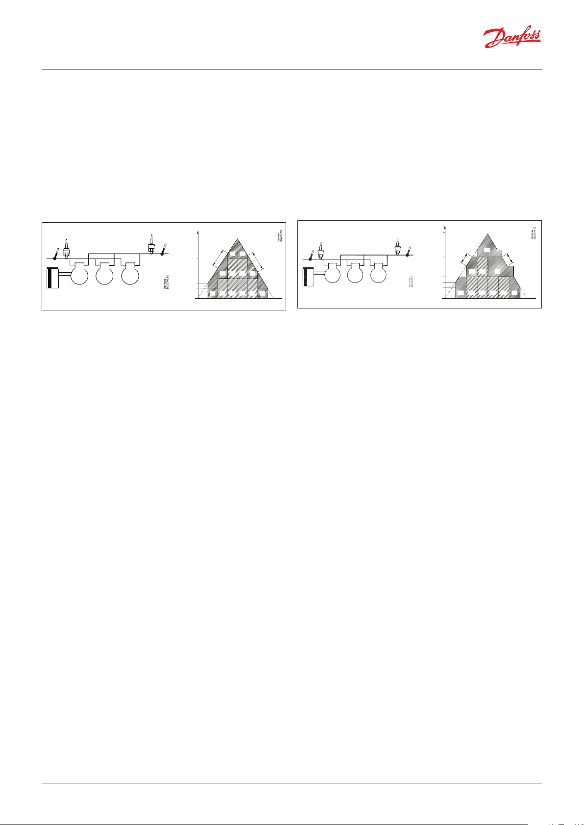
User Guide | Pack controller, type AK-PC 782A
Sd
a) Variable capacity bigger than following compressor steps:
When the variable part of the speed controlled compressor is
bigger than the following compressors, there will be no “holes” in
the capacity curve.
Example:
1 speed controlled compressor with a nominal capacity at 50Hz of
10kw - Variable speed range 30 – 90Hz
2 one step compressors of 10 kW
Fixed capacity = 30 HZ / 50 HZ x 10 kW = 6 kW
Variable capacity = 60 HZ / 50Hz x 10 kW = 12 kW
The capacity curve will look like this:
Requested
40 kW
20 kW
Start speed
Min. speed
capacity %
90 Hz
C1
40 Hz
C1
C3 C3 C1
C1 C2 C2 C2 C2 C1
80 Hz
C1
30 Hz
Time
Ss
Po
10 kW
30 – 90 Hz
10 kW 10 kW
Pc
Sd
As the variable part of the speed controlled compressor is bigger
than the following compressor steps, the capacity curve will be
without holes.
1 The speed controlled compressor will be cut in when the
requested capacity has reached the start speed capacity
2) The speed controlled compressor will increase speed until it
reaches max speed at a capacity of 18 kW
3) The one-step compressor C2 of 10 kW is cut in and the speed
on C1 is reduced too so that it corresponds to 8kW (40Hz)
4) The speed controlled compressor will increase speed until the
total capacity reaches 28 kw at max. speed
5) The one-step compressor C3 of 10 kW is cut in and the speed
on C1 is reduced too so that it corresponds to 8kW (40Hz)
6) The speed controlled compressor will increase speed until the
total capacity reaches 38 kW at max. speed
7) When reducing capacity, the one-step compressors will be cut
out when the speed on C1 is at minimum
b) Variable part smaller than following compressor steps:
If the variable part of the speed controlled compressor is smaller
than the following compressors there will be “holes” in the
capacity curve.
Example:
1 speed controlled compressor with a nominal capacity at 50Hz of
20kw - Variable speed range 25 – 50Hz
2 one step compressors of 20 kW
Fixed capacity = 25 HZ / 50 HZ x 20 kW = 10 kW
Variable capacity = 25 HZ / 50Hz x 20 kW = 10 kW
The capacity curve will look like this:
Requested
60 kW
capacity %
Ss
Po
20 kW
25 – 50 Hz
20 kW 20 kW
Pc
Start speed
Min. speed
40 kW
20 kW
50 Hz
25 Hz
C1
50 Hz
C1 C1C3
C1 C2 C2 C2 C2 C1
25 Hz
Time
As the variable part of the speed controlled compressor is smaller
than the following compressor steps, the capacity curve will have
some holes that cannot be filled out by the variable capacity.
1) The speed controlled compressor will be cut in when the
requested capacity has reached the start speed capacity
2) The speed controlled compressor will increase speed until it
reaches max. speed at a capacity of 20 kW
3) The speed controlled compressor will stay at max. speed until
the requested capacity has increased to 30 kW
4) The one-step compressor C2 of 20 kW is cut in and the speed
on C1 is reduced to min. so that it corresponds to 10kW (25Hz).
Total capacity = 30 kW.
5) The speed controlled compressor will increase speed until the
total capacity reaches 40 kW at max. speed
6) The speed controlled compressor will stay at max. speed until
the requested capacity has increased to 50 kW
7) The one-step compressor C3 of 20kW is cut in and the speed
on C1 is reduced to min. so that it corresponds to 10kW (25Hz).
Total capacity = 50 kW
8) The speed controlled compressor will increase speed until the
total capacity reaches 60 kw at max speed
9) When reducing capacity, the one step compressors will be cut
out when the speed on C1 is at minimum speed.
92 | BC245386497365en-000801 © Danfoss | Climate Solutions | 2022.02
Page 93

User Guide | Pack controller, type AK-PC 782A
Analogue output
Max. speed
me
Two speed-regulated compressors
The controller is capable of regulating the speed of two
compressors of the same or different sizes. The compressors can
be combined with one-step compressors of the same or different
sizes, depending on the choice of coupling pattern.
General regarding handling:
Generally, the two speed-regulated compressors are managed
according to the same principle as for one speed-regulated
compressor. The advantage of using two speed-regulated
compressors is that it allows for a very low capacity, which is an
advantage for low loads. At the same time, it produces a very large,
variable regulating area.
Compressor 1 and 2 both have their own relay outlets to start/stop
separate frequency converters, for example of type VLT.
Both frequency converters use the same analogue output signal
AO which is connected to the frequency converters’ analogue
signal input (they can, however, be configured to run individual
signals). The relay outputs will start and stop the frequency
converter and the analogue signal will indicate the speed.
The precondition for using this regulating method is that both
compressors have the same frequency range.
The speed-regulated compressors will always be the first to start
and the last to stop.
Pc
Po
Ss
20 kW 20 kW 40 kW
Sd
Cut-in
The first speed-regulated compressor will be started when there is
a capacity requirement which matches the setting.
The "Start speed" (relay outlet changes to on and the analogue
outlet is supplied with a voltage that matches this speed). It is now
up to the frequency converter to bring the speed up to the "Start
speed".
The capacity step will now be cut in and the desired capacity
determined by the controller.
The start speed should always be set so high that a good
lubrication of the compressor is quickly reached during start-up.
For a cyclical coupling pattern, the subsequent speed-regulated
compressor will be cut in when the first compressor runs at max.
speed and the desired capacity has reached a value that allows
the cut-in of the next speed-regulated compressor at start speed.
Afterwards, both compressors will be cut in together and will run
in parallel. The following one-step compressors will be cut in and
out in accordance with the selected coupling pattern.
Start speed
Min. speed
Comp. 1
Comp. 2
Comp. 3
Ti
Controlling – decreasing capacity
The speed-regulated compressors will always be the last
compressors running.
When the capacity requirement during cyclical operations
becomes less than "Min. speed" for both compressors, the speedregulated compressor with the most operating hours will be
cut-out. At the same time, the speed of the last speed-regulated
compressor increases so that the capacity is increased to the level
that matches the cut-out compressor’s step.
Cut-out
The last speed-regulated compressor will be cut-out when
the compressor has reached ”Min. speed” and the capacity
requirement (desired capacity) has decreased to under 1% (see
however the section on the pump down function).
Timer restriction and safety cut-outs
Timer limits and safety cut-outs on speed-regulated compressors
should be managed in accordance with the general rules for
individual coupling patterns.
Short descriptions and examples are given below of the handling
of two speed-regulated compressors for the individual coupling
patterns. For a more detailed description, refer to the appendix at
the end of the chapter.
Cyclical operation
For cyclical operations, both speed-regulated compressors will
have the same size and operating hours will be equalized between
the compressors in accordance with the First-in-First-Out Principle
(FIFO). The compressor with the least operating hours will be
the first to start. The following speed-regulated compressor will
be cut in when the first compressor runs at max. speed and the
desired capacity has reached a value that allows the cut-in of the
next speed-regulated compressor at start speed. Afterwards, both
compressors will be cut in together and they will run in parallel.
The following one-step compressors will be cut in and out in
accordance with First-In-First-Out principle in order to equalise
operating hours.
© Danfoss | Climate Solutions | 2022.02 BC245386497365en-000801 | 93
Page 94
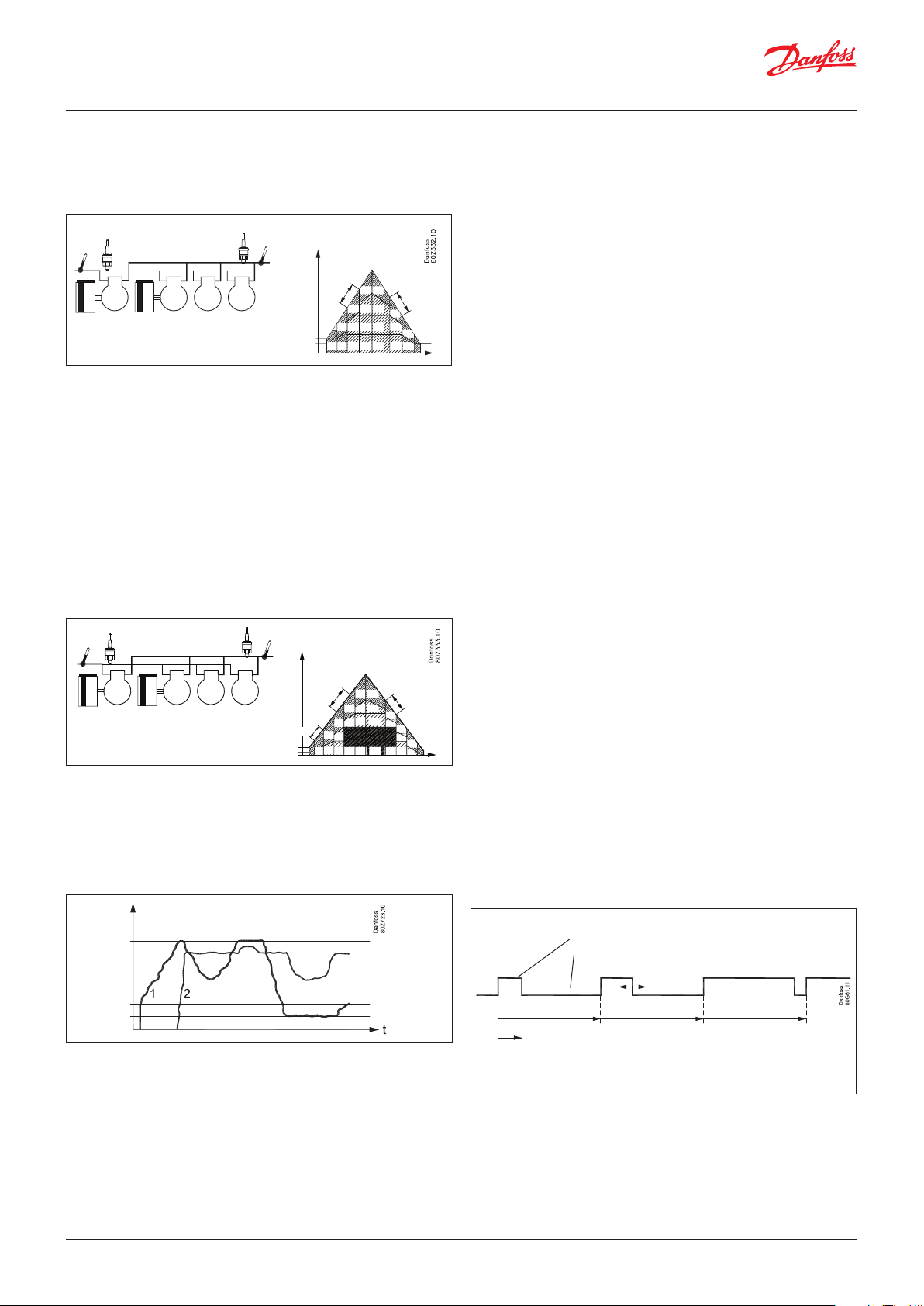
User Guide | Pack controller, type AK-PC 782A
t
Ss
Po
10 kW
30 – 90 Hz 30 – 90 Hz
20 kW 20 kW 40 kW
Pc
Sd
Cap. %
Start speed
t
90 Hz
C2 C2
C2
C2
C2
C2C1 C3C4 C4 C4
C3C3
C1
C1
C1 C1
C4 C3
C2
C1
C1
C2
C2
C1
56.7 Hz
90 Hz
45 Hz
63.3 Hz
30 Hz
Min. speed
Example:
• Two speed-regulated compressors with a nominal capacity of
20 kW and frequency range 25 – 60 Hz
• Two one-step compressors, each of 20 kW
Ss
20 kW
25 – 60 Hz
Po
Pc
20 kW 20 kW 20 kW
Sd
Start speed
Min. speed
Cap. %
35 Hz
C1C1 C3 C3 C3 C1C4
60 Hz
C2
C2
C2
C1
C1 C1C4 C4
50 Hz
C2
C1
C2
25 Hz
C2
Best fit
During best-fit operations, the speed-regulated compressors can
have different sizes and they will be handled in such a way that
the best possible capacity adjustment is achieved. The smallest
compressor will be started first, then the first will be cut out and
the second compressor will cut in. Finally, both compressors will
be cut in together and will run in parallel.
The following one-step compressors will, in every case, be
handled in accordance with the best-fit coupling pattern.
Example:
• Two speed-regulated compressors with a nominal capacity of
10 kW and 20 kW respectively
• Frequency range of 25-60 Hz
• Two one-step compressors of 20 and 40 kW respectively
5.2.3 Compressor timers
Time delays for cut-ins and cut-outs
To protect the compressor against frequent restarts, three time
delays can be put in:
• A minimum time to run from a compressor’s start-up and until it
may be restarted
• A minimum time (ON-time) for the compressor to operate
before it may be stopped again
• A minimum OFF time to run from a compressor stops and until it
may be restarted
When unloaders are cut in and out, the time delays will not be
used.
Timer
The operating time of a compressor motor is registered
continuously. You can read out:
• operating time for the previous 24-hour period
• total operating time since the timer was last set to zero-set
Equalizing operating hours
Operating hours are also summed in the "Equalization time" field.
During cyclical operation, this field is used for equalizing operating
hours.
Coupling counter
The number of relay cut-ins and cut-outs is registered
continuously. The number of starts can be read out here:
• Number during the previous 24-hour period
• Total number since the counter was last set to zero-set
Two independent speed-regulated compressors
If the two speed-regulated compressors need to be controlled
asynchronously, they must each have their own analogue voltage
signal.
The controller first starts one of the speed-regulated compressors.
If more capacity is required, the other speed-regulated
compressor is started, and then the single compressors.
Max. speed
Nominal
Start speed
Min. speed
The first is run up to maximum speed. Number two is then
activated and run up to nominal speed – and kept there. The
speed of number one is reduced at the same time, so the capacity
is balanced. All variations are now handled by number one. If
number one reaches maximum speed, number two will also be
raised.
If number one reaches minimum speed, it will be kept there while
number two takes over the variation below its nominal speed.
When engaging and disengaging, the total hours of operation for
the compressors is compared, so they are run an equal number of
hours.
94 | BC245386497365en-000801 © Danfoss | Climate Solutions | 2022.02
Analogue outputs
5.2.4 Compressor with variable capacity
Digital scroll compressor
The capacity is divided into period times as "PWM per". 100%
capacity is delivered when cooling takes place for the whole
period.
An off time is required by the by-pass valve within the period and
an on time is also permitted. There is "no cooling" when the valve
is on.
The controller itself calculates the capacity needed and will then
vary it according to the cut-in time of the by-pass valve.
A limit is introduced if low capacity is needed so that the cooling
does not go below 10%. This is because the compressor can cool
itself. This value can be increased if necessary.
Refrigeration
No refrigeration
Period time
Min. capacity
Page 95

User Guide | Pack controller, type AK-PC 782A
Copeland Stream compressor
The PWM signal can also be used to control one stream
compressor with one unloader valve (Stream 4) or one with two
unloaders (Stream 6).
Stream 4: The compressor capacity is distributed by up to 50% for
one relay and the remaining 50-100% for the unloader.
Stream 6: The compressor capacity is distributed by up to 33% for
one relay and the remaining 33-100% for the unloader.
Bitzer CRII Ecoline
CRII 4: The pulse signal can also be used to control one CRII with
two unloaders (4-cylinder version).
The compressor capacity can be controlled from 10 to
100%, depending on the pulsation of the unloaders. The
compressor start signal is connected to a relay output, and
the unloaders are connected to solid state output e.g. DO1
and DO2.
Unloader 1
Unloader 2
Unloader 2 follows unloader 1,
but it remains displaced by a
half period.
CRII 6: The pulse signal can also be used to control one CRII with
three unloaders (6-cylinder version).
The compressor signal is connected to one relay output.
The two unloaders are connected to solid state output fx
DO1 and DO2. The third is connected to a relay output.
The compressor capacity can be controlled from 10 to
67%, depending on the pulse of the unloaders.
The relay is then connected to the third unloader. When
this relay is off, the capacity will be controlled between 33
and 100%.
Individual Sd monitoring
When regulating with Sd monitoring, one of the three compressor
types will increase capacity if the temperature nears the Sd limit.
This will result in better cooling of the unloaded compressor.
© Danfoss | Climate Solutions | 2022.02 BC245386497365en-000801 | 95
Page 96
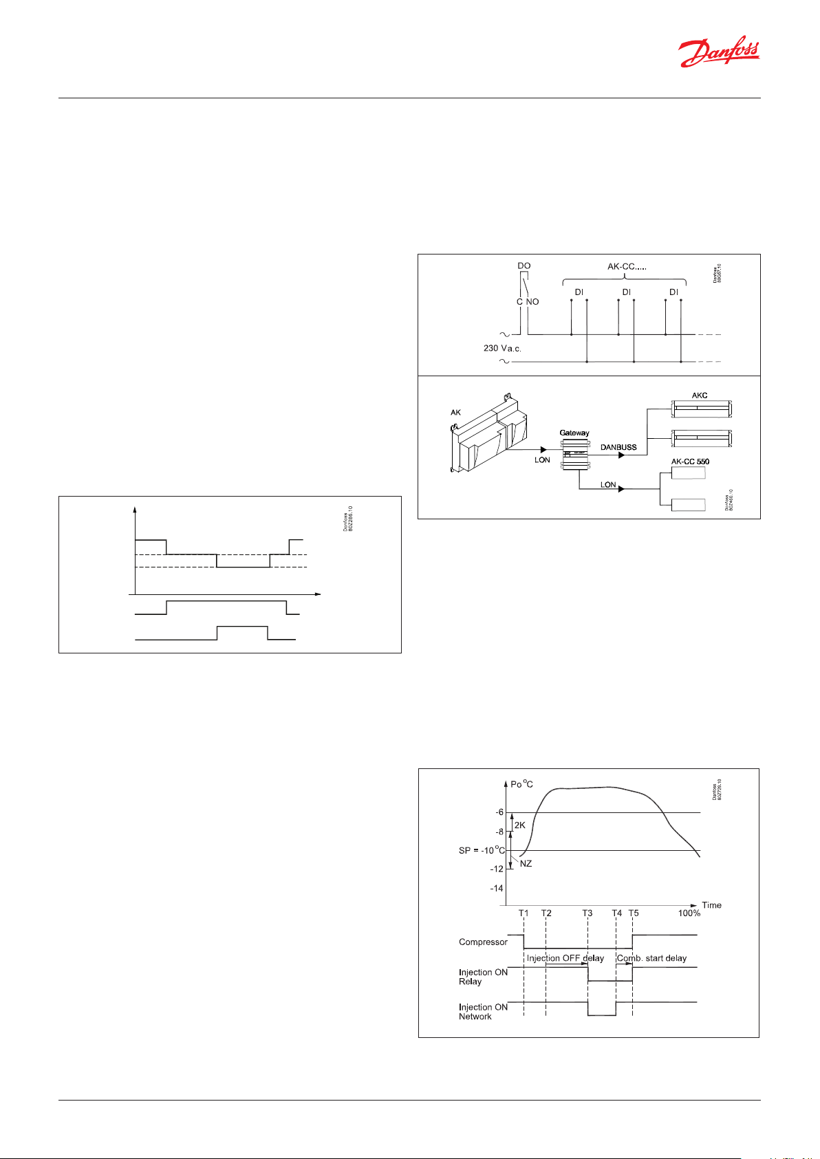
User Guide | Pack controller, type AK-PC 782A
Comp. cap. %
5.2.5 Load shedding
On some installations there is the desire to limit the cut-in
compressor capacity so that one can limit the total electrical load
in the store for periods. (The IT circuit is not directly affected)
This limitation can be activated in the following way:
• Via signal from the network
• Via signal on one DI input + signal via the network
• Via signal on two DI inputs + signal via the network
The signal via the network will result in the same function as if the
signal was received on DI 1.
For each digital inlet a limit value is attached for the maximum
allowable cut-in compressor capacity so that one can carry out the
capacity limitation in 2 steps.
When a digital inlet is activated, the maximum allowable
compressor capacity is limited to the set limit. This means that if
the actual compressor capacity upon activation of the digital inlet
is higher than this limit, then so much compressor capacity is cut
out that it will then be on or under the set maximum limit value for
this digital inlet.
The threshold value may not be set lower than the compressor's
lowest capacity step/"Start speed".
100%
80%
60%
40%
20%
Load shed DI 1
Load shed DI 2
When both load-shedding signals are active, the lowest limit value
for the capacity will be the one that is applicable.
Load limit 1
Load limit 2
5.2.6 Injection ON
The electronic expansion valves in the refrigeration appliances
must be closed when all the compressors are prevented from
starting. In this way the evaporators will not be filled with liquid
which is subsequently passed on to a compressor when regulation
is restarted.
One of the compressor control relays may be used for this
function, or the function can be obtained via data communication.
with relay
with data communication
The function is described based on the sequence of events below:
T1) The last compressor is cut out
T2) The suction pressure has increased to a value corresponding
to Po Ref + ½ NZ + 2 K” but no compressor can start due to restart timers or safety cut-out
T3) The time delay “Injection OFF delay” elapses and the injection
valves are forced to close via relay signal or via network signal
T4) The first compressor is now ready to start. The forced closure
signal via the network is now cancelled.
T5) The time delay “Comp. Start delay” expires and the forced
closure signal via the relay switch is cancelled simultaneously
with the first compressor being allowed to start
Max. time
A max. period with low compressor capacity can be set. When the
period expires, the system switches to normal regulation until the
suction pressure is once again in place. Load shedding will then be
permitted.
Overriding of load shedding:
To avoid load shedding leading to temperature problems for the
chilled products, an overriding function is fitted.
A overriding limit is set for the suction pressure as well as a delay
time for each digital inlet.
If the suction pressure during load shedding exceeds the set P0
overriding limit and the attached delay times for the two digital
inlets expire, then load shedding overrides the signals so that the
compressor capacity can be increased until the suction pressure
is again under the normal reference value. The load shedding can
then be activated again.
Alarm:
When a load shedding digital inlet is activated, an alarm will be
activated to inform that the normal control has been bypassed.
This alarm can however be suppressed if so desired.
The reason why the forced closure signal via the network is
cancelled before the first compressor starts, is that it will take
some time to distribute the signal to all appliance controllers via
the network.
96 | BC245386497365en-000801 © Danfoss | Climate Solutions | 2022.02
Page 97

User Guide | Pack controller, type AK-PC 782A
5.2.7 Liquid injection in common suction line
The discharge pressure gas temperature can be kept down by
means of liquid injection into the suction line (not IT circuit).
With a thermostatic expansion valve in series with a solenoid
valve. The solenoid valve is connected to the controller.
Ss Po Sd
NC
Inject diff. Sd
Inject start Sd
Sd
Ss
Inject diff. SH
Inject start SH
Control can be carried out in two ways:
1. The liquid injection is exclusively controlled on the basis of the
superheat in the suction line. Two values are set – a starting
value and a differential where the injection is stopped again.
2. The liquid injection is both controlled by the superheat (as
described above) and by discharge temperature Sd. Four values
are set – two as mentioned above and two for the Sd function,
a starting value and a differential. The liquid injection is started
when both starting values have been passed, and is stopped
again when just one of the two functions cuts out.
Direct using an electrically operated expansion valve of the type AKV
Four values are adjusted - a start value for the Sd temperature,
min. and max. values for overheating and a period time for the
AKV valve.
Actual used OD for the liquid injection is the highest of the two
above (see above fig.)
The width of the P-Band for the Sd control is hardcoded to be 20K
and cannot be changed.
The valve will be closed too, when all compressors are stopped.
As a safety function the AKV valve will be closed anyway, as
soon as the SH gets below 8K, to protect the compressors from
getting liquid into the suction port.
The pulse width modulating signal for the AKV valve shall be taken
from one of the controller's four solid state outputs.
Time delay
A time delay can be set which ensures that the injection is delayed
with the set value after start-up of the first compressor.
Calculation of OD% for the injection into the suction line
AKV OD% as function of SH
AKV OD% as function of Sd
© Danfoss | Climate Solutions | 2022.02 BC245386497365en-000801 | 97
Page 98

User Guide | Pack controller, type AK-PC 782A
5.2.8 Safety functions
Signal from the compressor’s safety controls
The controller can monitor the status of each compressor’s safety
circuit. The signal is taken directly from the safety circuit and
connected to an input.
(The safety circuit must stop the compressor without involving the
controller).
If the safety circuit is cut out, the controller will cut out all
output relays for the compressor in question and give an alarm.
Regulation will continue with the other compressors.
General safety circuit
If a low-pressure switch is placed in the
safety circuit it must be placed at the end
of the circuit. It must not cut out the DI
signals. (There is a risk that the regulation
will become locked and that it will not
start again). This also applies to the
example below.
If an alarm is needed which also monitors
the low-pressure thermostat, a “general
alarm” can be defined (an alarm that does
not affect the control).
See the following section “General
monitoring functions”.
Extended safety circuit
Instead of a general monitoring of the safety circuit this monitoring
function can be extended. In this way, a detailed alarm message is
issued which tells you which part of the safety circuit has dropped out.
The sequence of the safety circuit must be established as shown, but
not all of them need necessarily be used.
Oil pressure safety
Over current safety
Motor protect. safety
Discharge temp. safety
Discharge pressure safety
Common safety circuit
A common safety signal can also be received from the whole suction
group. All compressors will be cut out when the safety signal cuts out.
The function may not be connected to an external main switch.
Time delays with safety cut-out:
In connection with safety monitoring of a compressor it is possible
to define two delay times:
Cut-out delay time: Delay time from signal from the safety circuit
until the compressor relays cut out and alarm is given (note that
the delay time is common to all security inlets for the compressor
concerned)
Safety re-start time: The minimum time a compressor must be OK
after a safety cut-out until it may start again.
Monitoring of superheat
This function is an alarm function which continuously receives
measured data from suction pressure P0 and suction gas Ss.
If superheat is registered which is lower or higher than the set limit
values, an alarm will be given when the time delay has passed.
Monitoring of max. discharge gas temperature (Sd)
Common Sd monitoring
The function gradually cuts out compressor steps if the discharge
temperature becomes higher than permitted. The cut-out limit can
be defined in the range from 0 to +195°C.
The function is started at a value that is 10 K below the set value.
At this point the entire condenser capacity is cut in at the same
time as 25% of the compressor capacity is cut out (but minimum
one step). This is repeated every 30 seconds. The alarm function is
activated.
If the temperature rises to the set limit value all compressor steps
are immediately cut out.
The alarm is cancelled and renewed cut-in of compressor steps is
permitted when the following conditions are met:
- the temperature has dropped to 10 K below the limit value
- the time delay prior to restart has been passed (see later)
Normal condenser control is permitted again when the
temperature has dropped to 10 K below the limit value.
Individual Sd monitoring
The affected compressor will be disconnected here when the
temperature exceeds the threshold value.
- The piston compressor will be reconnected when the
temperature has dropped 10 K
- The screw compressor will be reconnected when the temperature
has dropped 20 K
- The capacity of compressors with variable capacity is increased
if the temperature is approaching the limit. Once it has been cut
out, it will only be connected when the temperature has dropped
10 K.
If signals are also obtained from the embedded NTC sensor, the
disconnect value for this temperature will always remain at 130
°C and the reconnect value at 120 °C.
98 | BC245386497365en-000801 © Danfoss | Climate Solutions | 2022.02
Page 99

User Guide | Pack controller, type AK-PC 782A
Monitoring of min. suction pressure (P0)
The function promptly cuts out all compressor steps if the suction
pressure becomes lower than the permitted value.
The cut-out limit can be defined in the range from -120 to +30°C.
The suction is measured with pressure transmitter P0.
At cut-out the alarm function is activated:
The alarm is cancelled and renewed cut-in of compressor steps is
permitted when the following conditions are met:
- the pressure (temperature) is above the cut-out limit
- the time delay has elapsed (see later).
Monitoring of max. condensing pressure (Pc)
The function cuts in all condenser steps and cuts out compressor
steps one by one if the condensing pressure becomes higher than
permitted. The cut-out limit is set in bar. The condensing pressure
is measured with pressure transmitter Pc_.
The function takes effect at a value which is 3 K below the set
value. At this time the entire condenser capacity is cut in at the
same time as 25% of the compressor capacity is cut out (but min.
one step). This is repeated every 30 seconds. The alarm function is
activated.
If the temperature (pressure) rises to the set limit value, the
following will happen:
- all compressor steps will immediately be cut out
- the condenser capacity will remain cut in
Delay of Pc max alarms
It is possible to delay the “Pc max alarm" message.
The controller will still disconnect the compressors, but the
sending of the alarm itself is delayed.
The delay is useful on cascade systems where the max. Pc limit is
used to disconnect compressors in the low-pressure circuit if the
high-pressure compressors have not started.
Time delay
There is a joint time delay for “Monitoring of max. discharge gas
temperature” and “Min. suction pressure”.
After a cut-out, regulation cannot be recommenced until the time
delay has been passed.
The time delay starts when the Sd temperature has again dropped
to 10 K below the limit value or P0 has risen above the P0 min.
value.
Alarm for too high suction pressure
An alarm limit can be set which will become effective when the
suction pressure becomes too high. An alarm will be transmitted
when the set time delay has been passed. The regulation
continues unchanged.
Monitoring max. receiver pressure
If the receiver pressure is approaching the max. value, the
compressors will be cut out as described under ‘Monitoring max.
condenser pressure’. An alarm will be transmitted when this limit is
exceeded.
The alarm will be cancelled and renewed cut-in of compressor
steps is permitted when the following conditions are met:
- the temperature (pressure) falls to 3 K below the limit value
- the time delay for restart has been passed
© Danfoss | Climate Solutions | 2022.02 BC245386497365en-000801 | 99
Page 100

User Guide | Pack controller, type AK-PC 782A
5.3 Oil management
Principle
The controller can control the pressure in an oil receiver and
ensure the evacuation of two oil separators.
The evacuation is carried out with a number of pulses, e.g. of 1
second duration followed by a pause of 1 minute.
The system can be controlled by signal from:
• Level switch on oil separator
• Pressure transmitter on oil receiver
All oil valves are closed when "Main switch" is Off.
Examples of oil circuits:
Separator 1
Receiver
Separator 1
Separator 2
Receiver
100 | BC245386497365en-000801 © Danfoss | Climate Solutions | 2022.02
 Loading...