

Design Guide
Capacity controller
AK-PC 710
ADAP-KOOL® Refrigeration control systems

Contents
1. Introduction ............................................................................. 3
Application .................................................................................................. 3
Function overview ............................................................................ 3
Principles...................................................................................................... 4
2. Design of the controller ..........................................................7
Module survey ........................................................................................... 8
Common data for modules .................................................................10
Controller ...........................................................................................12
Extension module AK-XM 102A / AK-XM 102B .....................14
Extension module AK-XM 204A / AK-XM 204B .....................16
Extension module AK-OB 110 ....................................................18
Extension module AK-OB 101A..................................................19
Extension module EKA 163B / EKA 164B / EKA 166 ............ 20
Power supply module AK-PS 075 ..............................................21
Select application ................................................................................... 22
General ................................................................................................ 22
Applications ...................................................................................... 22
Ordering ..................................................................................................... 33
3. Mounting and wiring .............................................................35
Mounting ................................................................................................... 36
Mounting of analog output module ........................................ 36
Mounting of extension module on the basic module ....... 37
Wiring .......................................................................................................... 38
4. Conguration and operation ................................................39
Conguration via service tool AK-ST 500 .......................................41
Connect PC or PDA ......................................................................... 41
Authorization .................................................................................... 42
Unlock the conguration of the controllers ..........................43
System setup ....................................................................................44
Set plant type ................................................................................... 45
Set control of compressors ..........................................................46
Setup control of condenser .........................................................49
Conguration of inputs and outputs .......................................50
Set alarm priorities..........................................................................52
Lock conguration ..........................................................................54
Check conguration .......................................................................55
Check of connections ............................................................................ 57
Check of settings.....................................................................................59
Schedule function .................................................................................. 61
Installation in network .......................................................................... 62
First start of control ................................................................................63
Start the control ............................................................................... 64
Manual capacity control ............................................................... 65
Quick setup ............................................................................................... 66
EKA 164, EKA 166 or AKM operation ...............................................67
5. Regulating functions .............................................................73
Suction group ..........................................................................................74
Controlling sensor...........................................................................74
Reference ...........................................................................................74
Capacity control of compressors ...............................................75
Capacity distribution methods ........................................... 76
Power pack types – compressor combinations ............77
Compressor timers ..................................................................79
Load shedding ..........................................................................80
Injection ON .............................................................................. 80
Safety functions ............................................................................... 81
Condenser ................................................................................................. 82
Capacity control of condenser ...................................................82
Reference for condensing pressure ..........................................82
Capacity distribution ..................................................................... 84
Step regulation ........................................................................................84
Speed regulation ....................................................................................84
Condenser couplings .....................................................................84
Safety functions for condenser .................................................. 85
Separate monitoring functions .........................................................85
Miscellaneous ..........................................................................................86
Appendix A – Compressor combinations and coupling pat-
terns ............................................................................................................. 89
2 Capacity controller RS8FT502 © Danfoss 08-2015 AK-PC 710
1. Introduction
Application
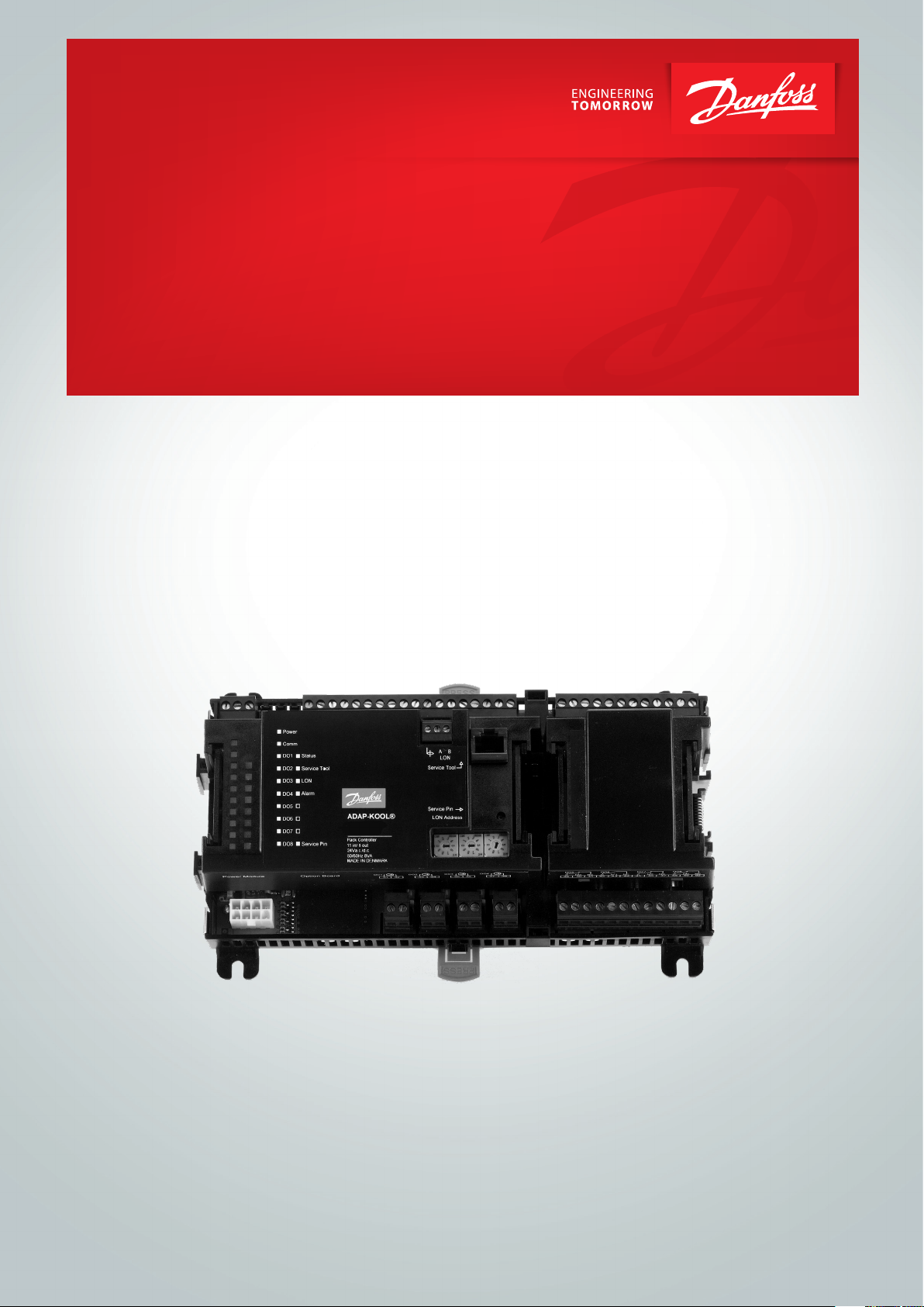
AK-PC 710 is a complete regulating unit for capacity control of
compressors and condensers in refrigeration systems.
In addition to capacity control the controllers can give signals to
other controllers about the operating condition, e.g. forced closing of expansion valves, alarm signals and alarm messages.
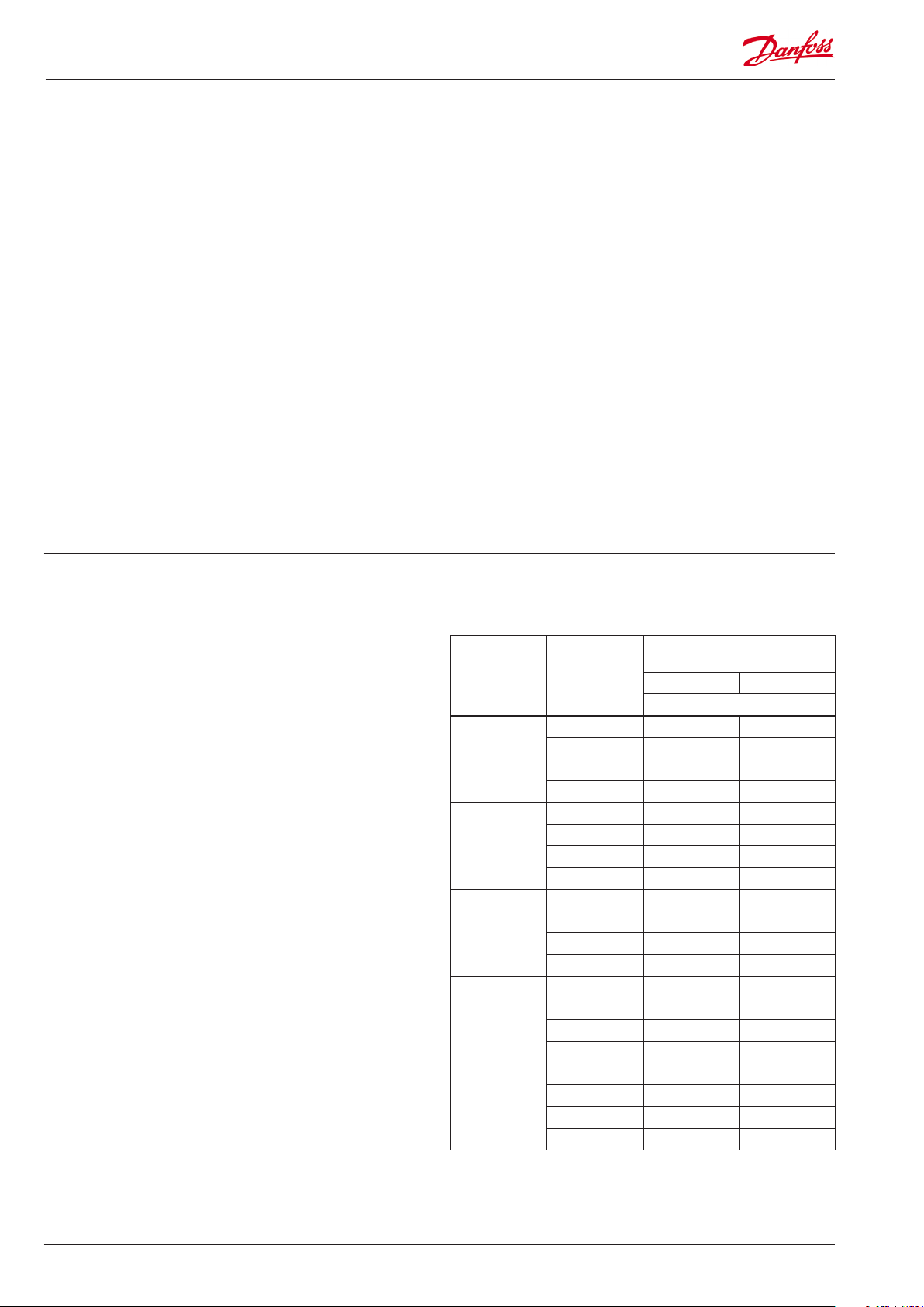
Function overview
AK-PC 710
Application
Regulation of a compressor group x
Both compressor group and condenser group x
Regulation of compressor capacity
Regulation sensor P0
PI-regulation x
Max. number of compressor steps 6
Identical compressor capacities x
Dierent compressor capacities x
Sequential operation (rst in / last out) x
Speed regulation of 1 compressor x
Run time equalisation x
Min. restart time x
Min. On-time/ Min O time x
Suction pressure reference
Override via P0 optimization x
Override via “night setback” x
The controller’s main function is to control compressors and
condensers so that operation all the time takes place at the
energy-optimum pressure conditions. Both suction pressure
and condensing pressure are controlled by signals from pressure
transmitters.
Capacity control can be carried out by suction pressure P0.
Among the dierent functions are:
- Capacity control of up to 6 compressors
- Speed control of one compressor
- One safety input for each compressor
- Option for capacity limitation to minimize consumption peaks
- When the compressor stops, signals can be transmitted to appliance controllers so that the electronic expansion valves will be
closed (signal via data communication)
- Safety monitoring of high pressure / low pressure / discharge
temperature
- Capacity control of up to 6 fans
- Step coupling, speed regulation or a combination
- Floating reference with regard to outside temperature
- Safety monitoring of fans
- The status of the outputs and inputs is shown by means of lightemitting diodes on the front panel
- Alarm signals can be generated directly from the controller and
via data communication
- Alarms are shown with texts so that the cause of the alarm is
easy to see.
- Plus some completely separate functions that are totally independent of the regulation – such monitoring of liquid level and
room temperature.
Regulation of condenser capacity
Regulation sensor Pc
Step regulation x
Max. number of steps 6
Speed regulation x
Step and speed regulation x
Condenser pressure reference
Floating condensing pressure reference x
Safety functions
Min. suction pressure x
Max. suction pressure x
Max. condensing pressure x
Max. discharge gas temperature x
Min. / Max. superheat x
Safety monitoring of compressors x
Common high pressure monitoring of compressors x
Common low pressure monitoring of compressors x
Safety monitoring of condenser fans x
Monitoring of room temperature x
Monitoring of liquid level x
Monitoring of frequency converter (VSD) x
Miscellaneous
Inject On function via data communication x
Option for connection of separate display 2
Option for connection of graphic display 1
SW = 1.4
AK-PC 710 Capacity controller RS8FT502 © Danfoss 08-2015 3
Principles
The great advantage of this series of controllers is that it can
be extended as the size of the plant is increased. It has been
developed for refrigeration control systems, but not for any
specic application – variation is created through the read-in
software and extension with up to 3 modules.
It is the same modules that are used for each regulation and the
composition can be changed, as required. With these modules
(building blocks) there is up to 40 various kinds of regulations.
But it is you who must help adjusting the regulation to the actual
needs – these instructions will assist you to nd your way through
all the questions so that the regulation can be dened and the
connections made.
Controller
Top part
Advantages
• The controller’s size can “grow” as systems grow
• The software can be set for one or more regulations
• Several regulations with the same components
• Extension-friendly when systems requirements are changed
• Flexible concept:
- Controller series with common construction
- One principle – many regulation uses
- modules are selected for the actual connection requirements
- The same modules are used from regulation to regulation
Extension modules
Bottom part
The controller is the cornerstone of the regulation. The module has inputs and
outputs capable of handling small systems.
• The bottom part – and hence the terminals – are the same for all controller types.
• The top part contains the intelligence with software. This unit will vary according
to controller type. But it will always be supplied together with the bottom part.
• In addition to the software the top part is provided with connections for data
communication and address setting.
Examples
A regulation with few connections can
be performed with the controller module
alone
If the system grows and more functions have to be controlled, the regulation can be
extended.
With extra modules more signals can be received and more relays cut in and out
– how many of them – and which – is determined by the relevant application.
If there are many connections one or more
extension modules must be mounted
4 Capacity controller RS8FT502 © Danfoss 08-2015 AK-PC 710
Direct connection
Setup and operation of an AK controller must be accomplished via
the “AK-Service Tool” software program.
The programme is installed on a PC, and setup and operation of
the various functions are carried out via the controller’s menu
displays.
Displays
The menu displays are dynamic, so that dierent settings in one
menu will result in dierent setting possibilities in other menus.
A simple application with few connections will give a setup with
few settings.
A corresponding application with many connections will give a
setup with many settings.
From the overview display there is access to further displays for
the compressor regulation and the condenser regulation.
At the bottom of the display there is access to a number of general
functions, such as “time table”, “manual operation”, “log function”,
“alarms”, and “service” (conguration).
Network linking
The controller can be linked up into a network together with other
controllers in an ADAP-KOOL® refrigeration control system. After
the setup operation can be performed at a distance with, say, our
software program type AKM.
Users
The controller comes supplied with several languages, one of
which can be selected and employed by the user. If there are
several users, they may each have their choice of language. All
users must be assigned a user prole which either gives access to
full operation or gradually limits the operation to the lowest level
that only allows you “to see”.
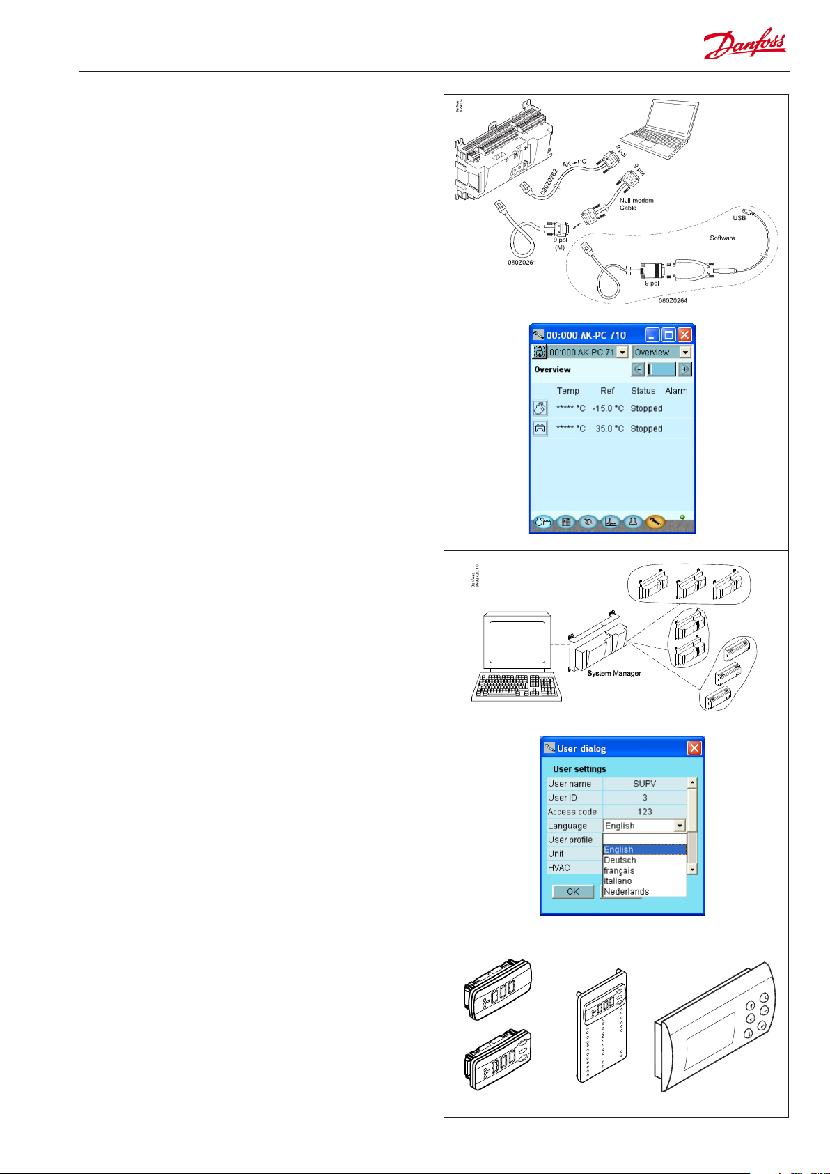
External display
An external display can be tted in order for P0 (Suction) and Pc
(Condensing) readings to be displayed.
The setup can be carried out on a display with control buttons.
The various functions are selected via a menu system.
If display of operational compressors, fans and functions is required, display type EKA 166 can be tted.
Med det graske display AK-MMI kan der både foretages opsætning og udlæsning.
AK-PC 710 Capacity controller RS8FT502 © Danfoss 08-2015 5
Light-emitting diodes
A number of light-emitting diodes makes it possible to follow the
signals that are received and transmitted by the controller.
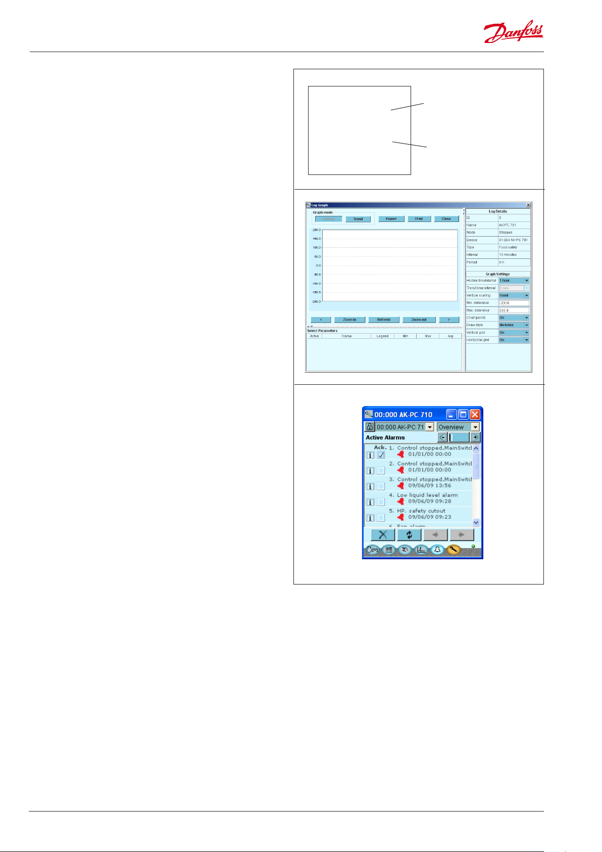
Log
From the log function you can dene the measurements you wish
to be shown.
The collected values can be printed, or you may export them to a
le. You can open the le in Excel.
If you are in a service situation you can show measurements in a
trend function. The measurements are then made real-time and
displayed instantly.
■ Power
■ Comm
■ DO1 ■ Status
■ DO2 ■ Service Tool
■ DO3 ■ LON
■ DO4
■ DO5 ■ Alarm
■ DO6
■ DO7
■ DO8 ■ Service Pin
Slow ash = OK
Quick ash = answer from gateway
Constantly ON = error
Constantly OFF = error
Flash = active alarm/not cancelled
Constant ON = Active alarm/cancelled
Alarm
The display gives you an overview of all active alarms. If you wish
to conrm that you have seen the alarm you can cross it o in the
acknowledge eld.
If you want to know more about a current alarm you can click on it
and obtain an information display on the screen.
A corresponding display exists for all earlier alarms. Here you can
upload information if you need further details about the alarm
history.
6 Capacity controller RS8FT502 © Danfoss 08-2015 AK-PC 710

2. Design of the controller
This controller can be congured to one of the 40 xed applications.
• There are 20 applications with dierent numbers of compressors
and condenser fans.
• The same applications can also be carried out with speed control
of one compressor.
• The condenser fans can be connected in steps or speed controlled.
The selected application has xed dened connecting points.
These cannot be changed.
In addition to the controller module, one or more of the following
modules should be used. The selected application determines:
• Output module with relays
• Input module for registering on/o signals
• Analogue output module for controlling one or two frequency
converters. One for one compressor and one for the condenser
fans.
This section denes the application and which modules should be
used.
AK-PC 710 Capacity controller RS8FT502 © Danfoss 08-2015 7
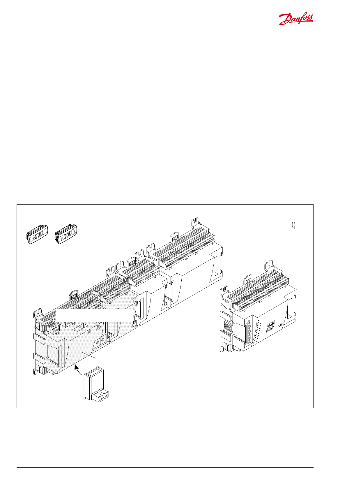
Module survey
• Controller module – capable of handling minor plant requirements.
• Extension modules. When the complexity becomes greater
and additional inputs or outputs are required, modules can be
attached to the controller. A plug on the side of the module will
transmit the supply voltage and data communication between
the modules.
• Top part
The upper part of the controller module contains the
intelligence. This is the unit where the regulation is dened and
where data communication is connected to other controllers in a
bigger network.
Extension module with
additional analog inputs
External display for
suction pressure etc.
• Connection types
There are various types of inputs and outputs. One type may, for
example, receive signals from sensors and switches, another may
receive a voltage signal, and a third type may be outputs with
relays etc. The individual types are shown in the table below.
• Fixed connection
When a regulation is planned (set up) it will generate a need
for a number of connections distributed on the mentioned
types. This connection must be made as shown in the following
diagrams.
Extension module with additional
relay outputs and additional
analog inputs.
Controller with analog inputs and
relay outputs.
Top part
Extension module with
2x analog output signals
The module with additional relay outputs is
also available in a version where the top part
is provided with change-over switches so
that the relays can be overridden.
8 Capacity controller RS8FT502 © Danfoss 08-2015 AK-PC 710
1. Controller
Type Function Application
AK-PC 710
Controller for capacity control of up to 6 compressors and up to 6 condenser fans
Compressor / Condenser / Both
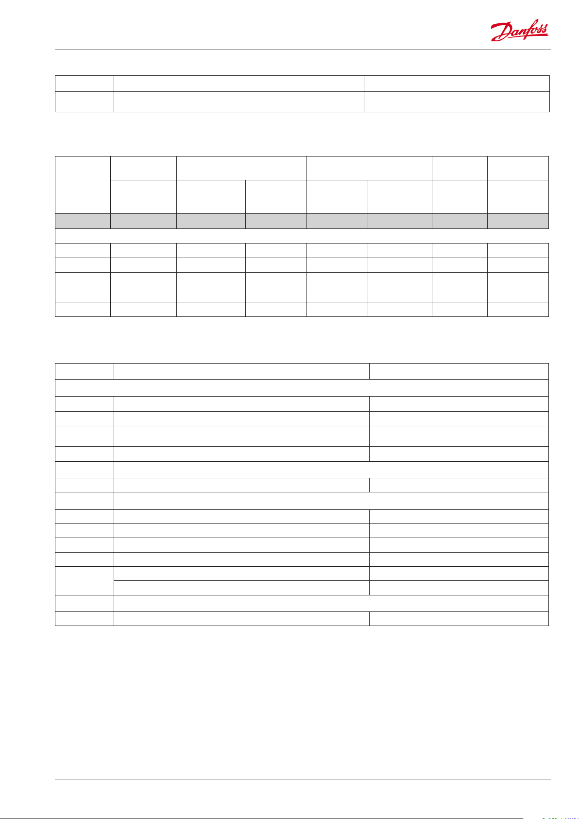
2. Extension modules and survey of inputs and outputs
Type Analog
inputs
For sensors, pressure transmitters
etc.
Controller 11 4 4 - - - -
Extension modules
AK-XM 102A 8
AK-XM 102B 8
AK-XM 204A 8
AK-XM 204B 8 x
AK-OB 110 2
On/O outputs On/o supply voltage
Relay
(SPDT)
Solid state Low voltage
(DI signal)
(max. 80 V)
High voltage
(max. 260 V)
Analog
outputs
0-10 V d.c. For override of
Module with
switches
relay outputs
3. AK operation and accessories
Type Function Application
Operation
AK-ST 500 Software for operation of AK controllers AK-operation
- Cable between PC and AK controller AK - Com port
-
- Cable between PC and AK controller AK- USB
Accessories Power supply module 230 V / 115 V to 24 V
AK-PS 075 18 VA Supply for controller
Accessories External display that can be connected to the controller module. For showing, say, the suction pressure
EKA 163B Display
EKA 164B Display with operation buttons
EKA 166 Display with operation buttons and LED's for inputs and outputs
AK-MMI Graphic display with operation
-
Accessories Real time clock for use in controllers that require a clock function, but are not wired with data communication.
AK-OB 101A Real time clock with battery backup. To be mounted in an AK controller
Cable between zero modem cable and AK controller /
Cable between PDA cable and AK controller
Cable between display and controller Length = 2 m, 6 m
Cable between graphic display and controller Length = 0.8 m, 1.5 m, 3 m
AK - RS 232
On the following pages there is data specic to each module.
AK-PC 710 Capacity controller RS8FT502 © Danfoss 08-2015 9
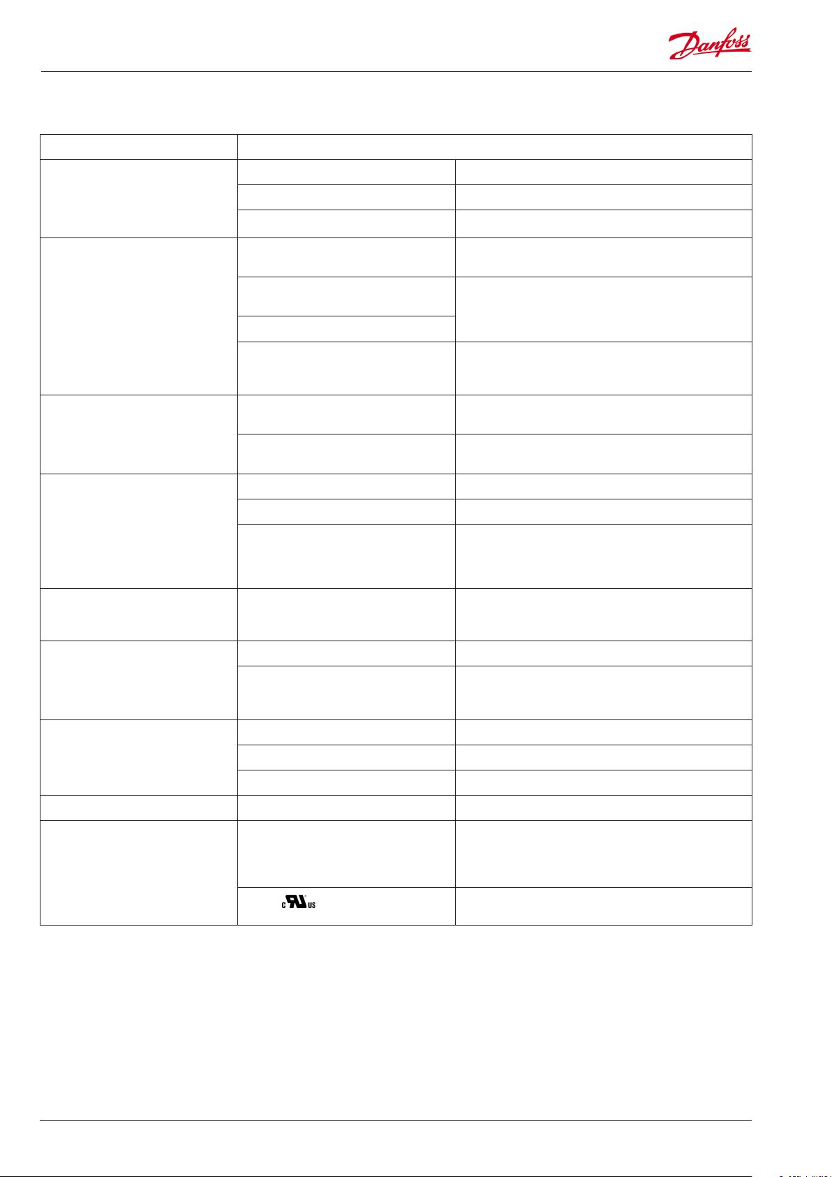
Common data for modules
Supply voltage 24 V d.c./a.c. +/- 20%
Power consumption AK-__ (controller) 8 VA
AK-XM 102 2 VA
AK-XM 204 5 VA
Analog inputs Pt 1000 ohm /0°C Resolution: 0.1°C
Pressure transmitter type AKS 32R /
AKS 32 (1-5 V)
Voltage signal 0-10 V
Contact function (On/O) On at R < 20 ohm
On/o supply voltage inputs Low voltage
Relay outputs
SPDT
Solid state outputs Used for control of compressor relay Max. 240 V a.c. , Min. 48 V a.c.
Ambient temperature During transport -40 to 70°C
0 / 80 V a.c./d.c.
High voltage
0 / 260 V a.c.
AC-1 (ohmic) 4 A
AC-15 (inductive) 3 A
U Min. 24 V
Accuracy: +/- 0.5°C
Resolution:1 mV
Accuracy +/- 10 mV
Max. connection of 5 pressure transmitters on one module
O at R > 2K ohm
(Gold -plated contacts not necessary)
O: U < 2 V
On: U > 10 V
O: U < 24 V
On: U > 80 V
Max. 230 V
Low and high voltage must not be connected to the same
output group
Max. 0.5 A,
Leak < 1 mA
During operation -20 to 55°C ,
0 to 95% RH (non condensing)
No shock inuences / vibrations
Enclosure Material PC / ABS
Class IP10 , VBG 4
Mounting For mounting on panel wall or DIN rail
Weight with screw terminals modules in100- / 200- / controller-series Ca. 200 g / 500 g / 600 g
Approvals EU low voltage directive and EMC require-
ments are complied with
UL 873,
The mentioned data applies to all modules.
If data is specic, this is mentioned together with the module in question.
Capacitive load
The relays cannot be used for the direct connection of capacitive loads such as LEDs
and on/o control of EC motors.
All loads with a switch mode power supply must be connected with a suitable contactor or similar.
LVD tested according to EN 60730
EMC tested
Immunity according to EN 61000-6-2
Emission according to EN 61000-6-3
UL le number: E166834 for XM
UL le number: E31024 for PC
10 Capacity controller RS8FT502 © Danfoss 08-2015 AK-PC 710
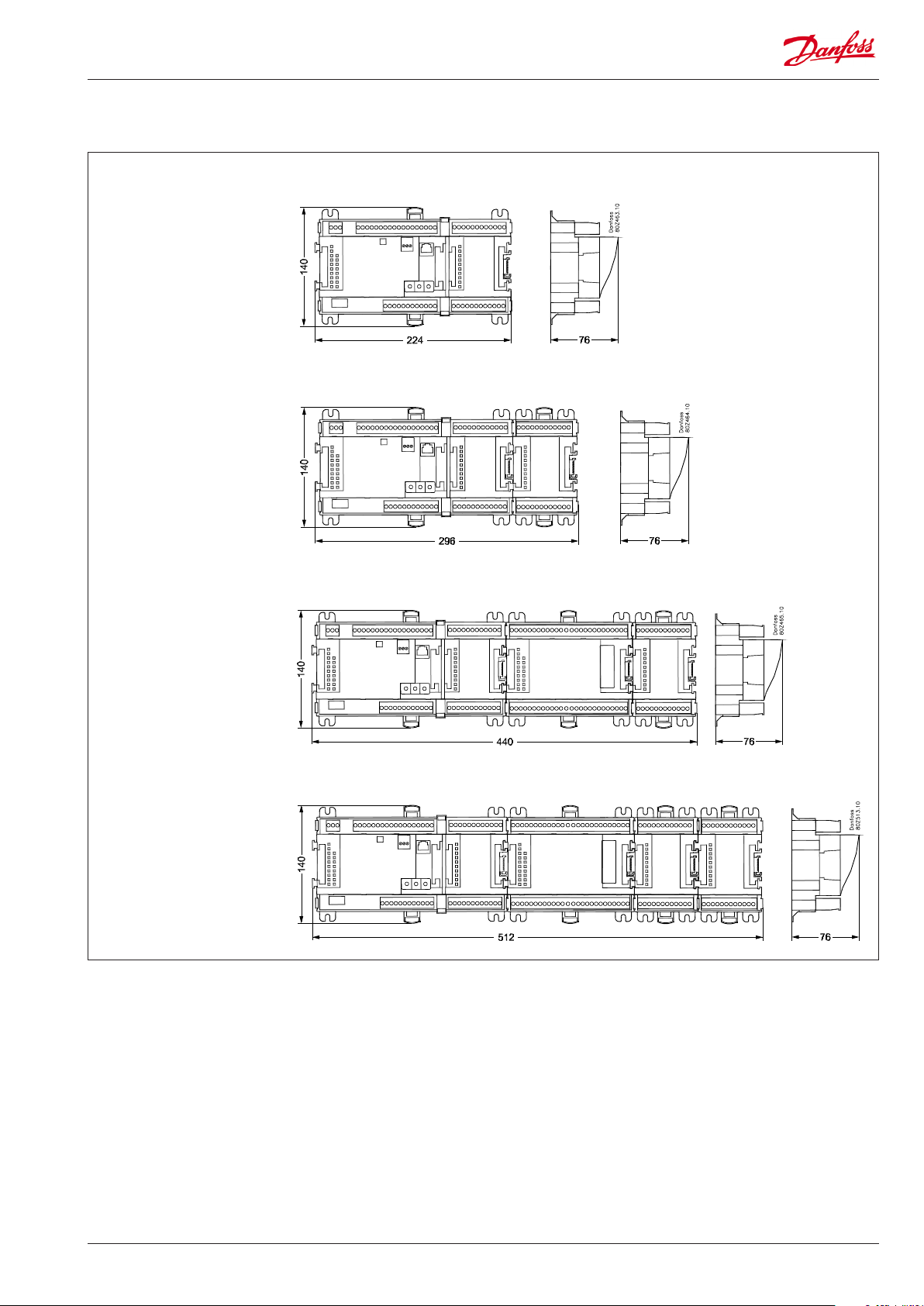
Dimensions
AK-PC 710
AK-PC 710 + AK-XM 102
AK-PC 710 + AK-XM 204 + AK-XM 102
AK-PC 710 + AK-XM 204 + AK-XM 102 + AK-XM 102
AK-PC 710 Capacity controller RS8FT502 © Danfoss 08-2015 11
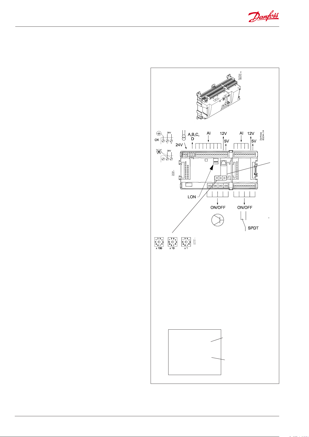
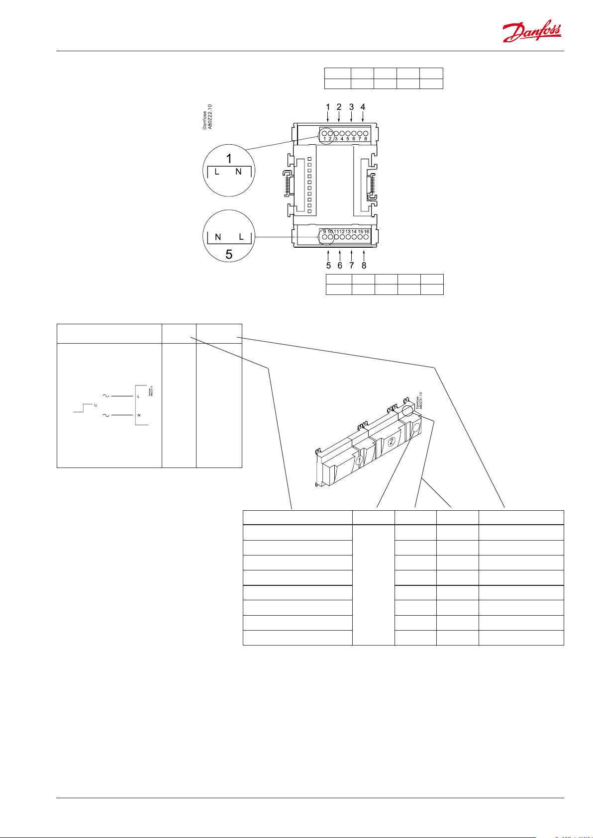
Controller
Function
There are several controllers in the series. The function is
determined by the programmed software, but outwardly the
controllers are identical – they all have the same connection
possibilities:
11 analog inputs for sensors, pressure transmitters, voltage signals
and contact signals.
8 digital outputs, with 4 Solid state outputs and 4 relay outputs
Supply voltage
24 V a.c. or d.c. to be connected to the controller.
The 24 V must not be retransmitted and used by other controllers
as it is not galvanically separated from inputs and outputs. In
other words, you must use a transformer for each controller. Class
II is required. The terminals must not be earthed.
The supply voltage to any extension modules is transmitted via
the plug on the right-hand side.
The size of the transformer is determined by the power
requirement of the total number of modules.
The supply voltage to a pressure transmitter can be taken either
from the 5 V output or from the 12 V output depending on
transmitter type.
PIN
Data communication
If the controller is to be included in a system, communication
must take place via the LON connection.
The installation has to be made as mentioned in the separate
instructions for LON communication.
Address setting
When the controller is connected to a gateway type AKA 245,
the controller’s address must be set between 1 and 119. (If it is a
system manager AK-SM .., then 1-999).
Service PIN
When the controller is connected to the data communication
cable the gateway must have knowledge of the new controller.
This is obtained by pushing the key PIN. The LED “Status” will ash
when the gateway sends an acceptance message.
Operation
The conguration operation of the controller must take place from
the software programme “Service Tool”. The program must be
installed on a PC, and the PC must be connected to the controller
via the network plug on the front of the unit.
Light-emitting diodes
There are two rows with LED’s. They mean:
Left row:
• Voltage supply to the controller
• Communication active with the bottom PC board (red = error)
• Status of outputs DO1 to DO8
Right row:
• Software status (slow ash = OK)
• Communication with Service Tool
• Communication on LON
• Alarm when LED ashes
- 3 LED’s that are not used
• “Service Pin” switch has been activated
Address
Keep the safety
distance!
Low and high
voltage must not
be connected to
the same output
group
■ Power
■ Comm
■ DO1 ■ Status
■ DO2 ■ Service Tool
■ DO3 ■ LON
■ DO4
■ DO5 ■ Alarm
■ DO6
■ DO7
■ DO8 ■ Service Pin
Slow ash = OK
Quick ash = answer from gateway
Constantly ON = error
Constantly OFF = error
Flash = active alarm/not cancelled
Constant ON = Active alarm/cancelled
A small module (option board) can be placed on the bottom part
of the controller. The module is described later in the document.
12 Capacity controller RS8FT502 © Danfoss 08-2015 AK-PC 710
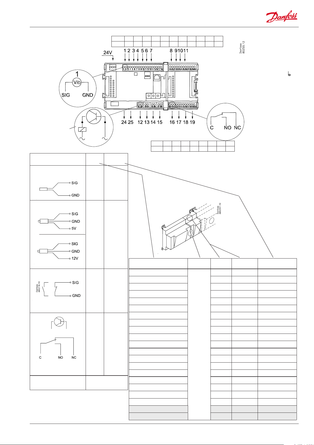
Point
Point 1 2 3 4 5 6 7 8 9 10 11
Type AI1 AI2 AI3 AI4 AI5 AI6 AI7 AI8 AI9 AI10 AI11
Terminal 15: 12 V
Terminal 16: 5 V
Terminal 27: 12 V
Terminal 28: 5 V
Analog
inputs
on 1 - 11
Solid state outputs
on 12 - 15
Relay
fx 230 V a.c.
Signal Signal
S
Pt 1000 ohm/0°C
Saux1
Sc3
SS
Sd
P
AKS 32R
3: Brown
2: Blue
1: Black
P0
Pc
AKS 32
3: Brown
2: Black
1: Red
On/O Ext.
Main
switch
Day/
Night
PLP
PHP
LL
DO
Comp 1-6
Fan 1
Alarm
Option Board
Please see the signal
on the page with the
module.
24 and 25 used
only when "Option board tted"
type
Pt 1000
AKS 32R/
AKS 2050
-1 - xx bar
AKS 32
-1 - zz bar
Active at:
Closed
/
Open
Active at:
On
/
O
Relay outputs on
16 - 19
Point 12 13 14 15 16 17 18 19
Type DO1 DO2 DO3 DO4 DO5 DO6 DO7 DO8
Signal Module Point
Terminal
1 (AI 1) 1 - 2
2 (AI 2) 3 - 4
3 (AI 3) 5 - 6
4 (AI 4) 7 - 8
5 (AI 5) 9 - 10
6 (AI 6) 11 - 12
7 (AI 7) 13 - 14
8 (AI 8) 19 - 20
9 (AI 9) 21 - 22
10 (AI 10) 23 - 24
11 (AI 11) 25 - 26
1
12 (DO 1) 31 - 32
Function and terminal number is mentioned in the actual diagram
13 (DO 2) 33 - 34
14 (DO 3) 35 - 36
15 (DO 4) 37 - 38
16 (DO 5) 39 - 40- 41
17 (DO6) 42 - 43 - 44
18 (DO7) 45 - 46 - 47
19 (DO8) 48 - 49 - 50
24 -
25 -
Terminal
17, 18, 29, 30:
(Cable screen)
Signal type /
Active at
AK-PC 710 Capacity controller RS8FT502 © Danfoss 08-2015 13
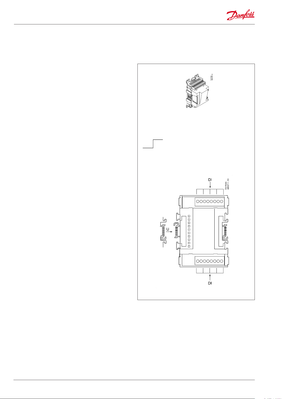
Extension module AK-XM 102A / AK-XM 102B
Function
The module contains 8 inputs for on/o voltage signals.
Signal
AK-XM 102A is for low voltage signals.
AK-XM 102B is for high voltage signals.
Supply voltage
The supply voltage to the module comes from the previous
module in the row.
Light-emitting diodes
They indicate:
• Voltage supply to the module
• Communication with the controller is active (red = error)
• Status of the individual inputs 1 to 8 (when lit = voltage)
AK-XM 102A
Max. 24 V
On/O:
On: DI > 10 V a.c.
O: DI < 2 V a.c.
AK-XM 102B
Max. 230 V
On/O:
On: DI > 80 V a.c.
O: DI < 24 V a.c.
14 Capacity controller RS8FT502 © Danfoss 08-2015 AK-PC 710
Point
DI
Point 1 2 3 4
Type DI1 DI2 DI3 DI4
Point 5 6 7 8
Type DI5 DI6 DI7 DI8
Signal Active at
AK-XM 102A: Max. 24 V
AK-XM 102B: Max. 230 V
Day/
Night
Comp.
safety 1-6
Cond.fan
safety
Closed
(voltage on)
/
Open
(voltage o)
Signal Module Point Terminal Active at
1 (DI 1) 1 - 2
2 (DI 2) 3 - 4
3 (DI 3) 5 - 6
4 (DI 4) 7 - 8
3 (2)
Function and terminal number is mentioned in the actual diagram
5 (DI 5) 9 - 10
6 (DI 6) 11 - 12
7 (DI 7) 13 - 14
8 (DI 8) 15 - 16
AK-PC 710 Capacity controller RS8FT502 © Danfoss 08-2015 15
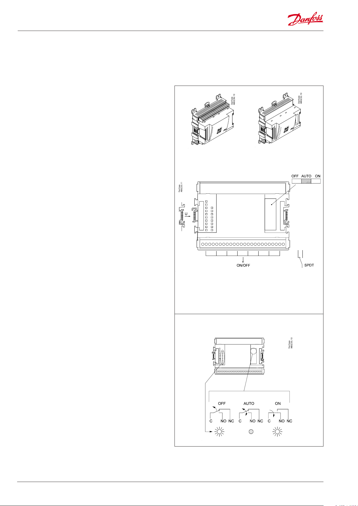
Extension module AK-XM 204A / AK-XM 204B
Function
The module contains 8 relay outputs.
Supply voltage
The supply voltage to the module comes from the previous
module in the row.
AK-XM 204B only
Override of relay
Eight change-over switches at the front make it possible to
override the relay’s function.
Either to position OFF or ON.
In position Auto the controller carries out the control.
Light-emitting diodes
There are two rows with LED’s. They indicate the following:
Left row:
• Voltage supply to the controller
• Communication active with the bottom PC board (red = error)
• Status of outputs DO1 to DO8
Right row: (AK-XM 204B only):
• Override of relays
ON = override
OFF = no override
AK-XM 204A AK-XM 204B
Fuses
Behind the upper part there is a fuse for each output.
Max. 230 V
AC-1: max. 4 A (ohmic)
AC-15: max. 3 A (Inductive)
AK-XM 204B
Override of relay
Keep the safety distance!
Low and high voltage
must not be connected to
the same output group
16 Capacity controller RS8FT502 © Danfoss 08-2015 AK-PC 710
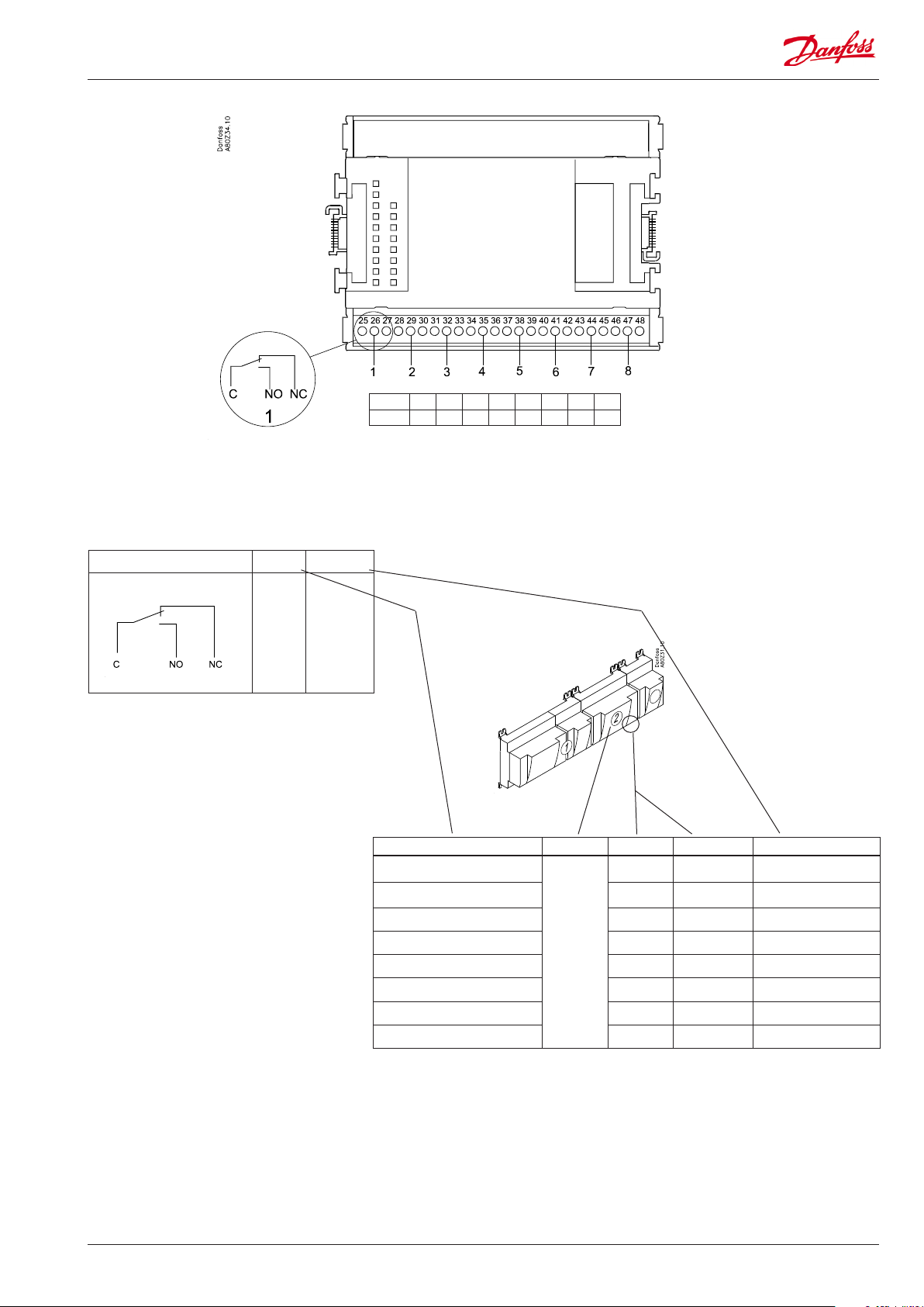
Point
DO
Signal Active at
On
Fans 1
Alarm
/
O
Point 1 2 3 4 5 6 7 8
Type DO1 DO2 DO3 DO4 DO5 DO6 DO7 DO8
Signal Module Point Terminal Active at
1 (DO 1) 25 - 27
2 (DO 2) 28 - 30
3 (DO 3) 31 - 33
2
4 (DO 4) 34 -36
5 (DO 5) 37 - 39
6 (DO 6) 40 - 41 - 42
7 (DO 7) 43 - 44 - 45
Function and terminal number is mentioned in the actual diagram
8 (DO 8) 46 - 47 - 48
AK-PC 710 Capacity controller RS8FT502 © Danfoss 08-2015 17
Extension module AK-OB 110
Function
The module contains two analog voltage outputs of 0 – 10 V.
Supply voltage
The supply voltage to the module comes from the controller
module.
Placing
The module is placed on the PC board in the controller module.
Point
The two outputs have points 24 and 25. They are shown on the
earlier page where the controller is also mentioned.
Max. load
I < 2.5 mA
R > 4 kohm
AO AO1:
Comp.speed
AO2:
Cond.speed
0 - 10 V
Module
Point 24 25
Type AO1 AO2
1
AO2
AO1
18 Capacity controller RS8FT502 © Danfoss 08-2015 AK-PC 710
Extension module AK-OB 101A
Function
The module is a real time clock module with battery backup.
The module can be used in controllers that are not linked up in
a data communication unit together with other controllers. The
module is used here if the controller needs battery backup for the
following functions
• Clock function
• Fixed times for day/night change-over
• Saving of alarm log in case of power failure
• Saving of temperature log in case of power failure
Connection
The module is provided with plug connection.
Placing
The module is placed on the PC board inside the top part.
Point
No point for a clock module to be dened – just connect it.
Working life of the battery
The working life of the battery is several years – even if there are
frequent power failures.
An alarm is generated when the battery has to be replaced.
After the alarm there are still several months of operating hours
left in the battery.
AK-PC 710 Capacity controller RS8FT502 © Danfoss 08-2015 19
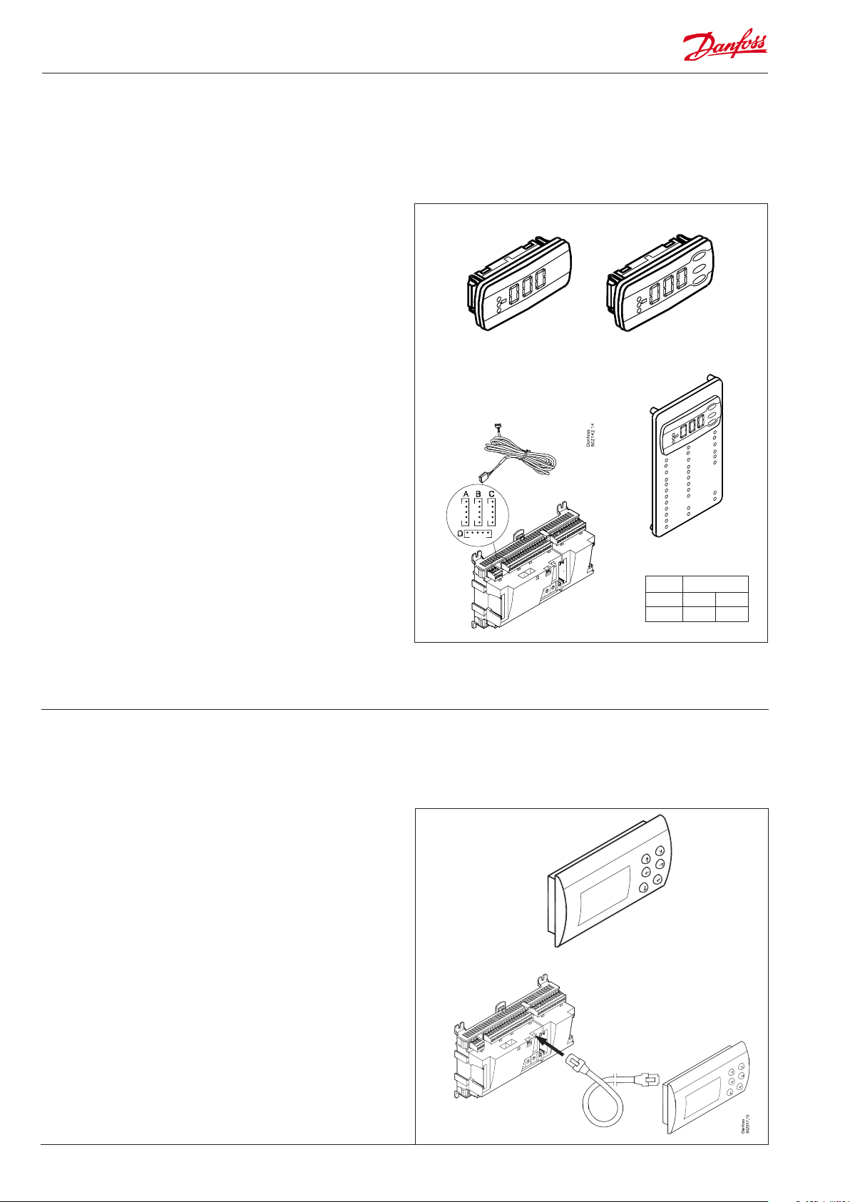
Extension module EKA 163B / EKA 164B
Function
Display of important measurements from the controller, e.g.
suction pressure or condensing pressure.
Setting of the individual functions can be performed by using the
display with control buttons.
Connection
The extension module is connected to the controller module via
a cable with plug connections. You have to use one cable per
module. The cable is supplied in various lengths.
Both types of display (with or without control buttons) can be
connected to either display output A, and B.
A = P0 . Suction pressure in °C
B = Pc. Condensing pressure in °C
EKA 166 further includes a number of LEDs to make it possible to
follow individual functions.
When the controller starts up, the display will show which output
is connected. - - 1 = output A, - - 2 = output B, etc.
Placing
The extension module can be placed at a distance of up to 15 m
from the controller module.
EKA 163B EKA 164B
EKA 166
Module
Point - -
Type - -
1
Point
No point has to be dened for a display module – you simply
connect it.
Graphic display AK-MMI
Function
Setting and display of values in the controller.
Connection
The display connects to the controller via a cable with plug connections. Use plug RJ45 to connect to the controller; the same
plug is also used for service tool AK-ST 500.
Supply voltage
24 V a.c. / d.c. 1.5 VA.
Placing
The display can be placed at a distance of up to 3 m from the
controller.
Point
No point has to be dened for a display – you simply connect it.
20 Capacity controller RS8FT502 © Danfoss 08-2015 AK-PC 710
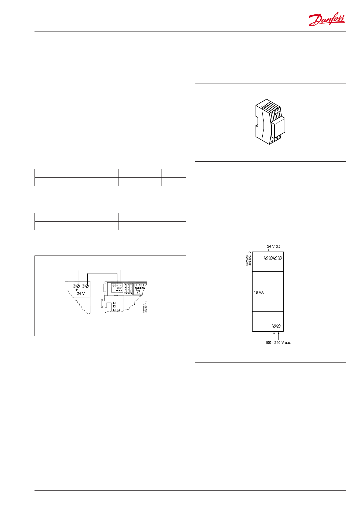
Power supply module AK-PS 075
Function
24 V supply for controller.
Supply voltage
230 V a.c or 115 V a.c. (from 100 V a.c. to 240 V a.c.)
Placing
On DIN-rail
Eect
Type Output tension Output current Power
AK-PS 075 24 V d.c. 0.75 A 18 VA
Dimension
Type High Width
AK-PS 075 90 mm 36 mm
Connections
Supply to a controller
AK-PS 075
AK-PC 710 Capacity controller RS8FT502 © Danfoss 08-2015 21
Select application
General
Clock function
Clock function and change-over between summer time and
winter time are contained in the controller.
The clock is zeroset when there is power failure.
The clock’s setting is maintained if the controller is linked up in a
network with a gateway, a system manager or a clock module can
be mounted in the controller.
Start/stop of regulation
Regulation can be started and stopped via the software or via an
input on the controller module
Application
40 examples of application are shown in the following: Select the
one that ts your system.
Wiring should be done as shown, and the controller should be
set for this application.
Regarding speed regulation
An option board has 2 outputs:
No. 1 is dedicated to the compressor
No. 2 is dedicated to the condenser fans
If you do not use speed control, disregard the shown 0-10 V
outputs.
It is only the compressor connection that is shown in all examples,
but output 2 can be used for condenser fans at will.
If the speed control needs a start/stop signal, this should be taken
from output "Compressor 1" or from "Fan 1".
Forced control
The software contains a forced control option. If an extension
module with relay outputs is used, the module’s top part can
be with change-over switches – switches that can override the
individual relays into either OFF or ON position.
Data communication
The controller module has terminals for LON data communication.
The requirements to the installation are described in a separate
document.
Number of
compressors
2 0 1 21
3 0 5 25
4 0 9 29
5 0 13 33
6 0 17 37
Number of
condenser fans
2 2 22
3 3 23
4 4 24
3 6 26
4 7 27
5 8 28
3 10 30
4 11 31
5 12 32
4 14 34
5 15 35
6 16 36
4 18 38
5 19 39
6 20 40
Speed regulation on one compressor
Yes No
Application no.
22 Capacity controller RS8FT502 © Danfoss 08-2015 AK-PC 710
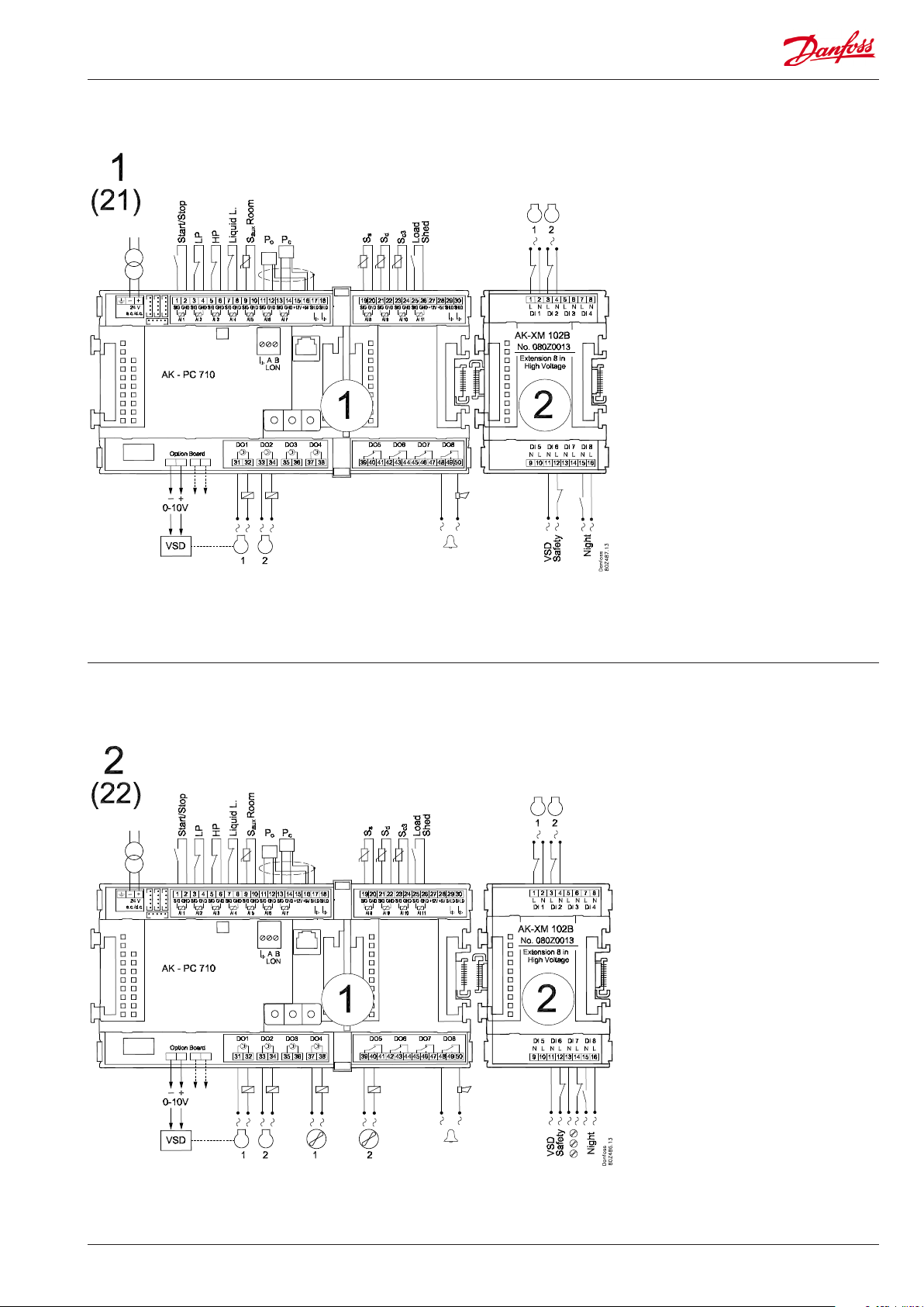
Application 1 and 21 (for 21 leave out the VSD connection on the option board)
Application 2 and 22 (for 22 leave out the VSD connection on the option board)
AK-PC 710 Capacity controller RS8FT502 © Danfoss 08-2015 23
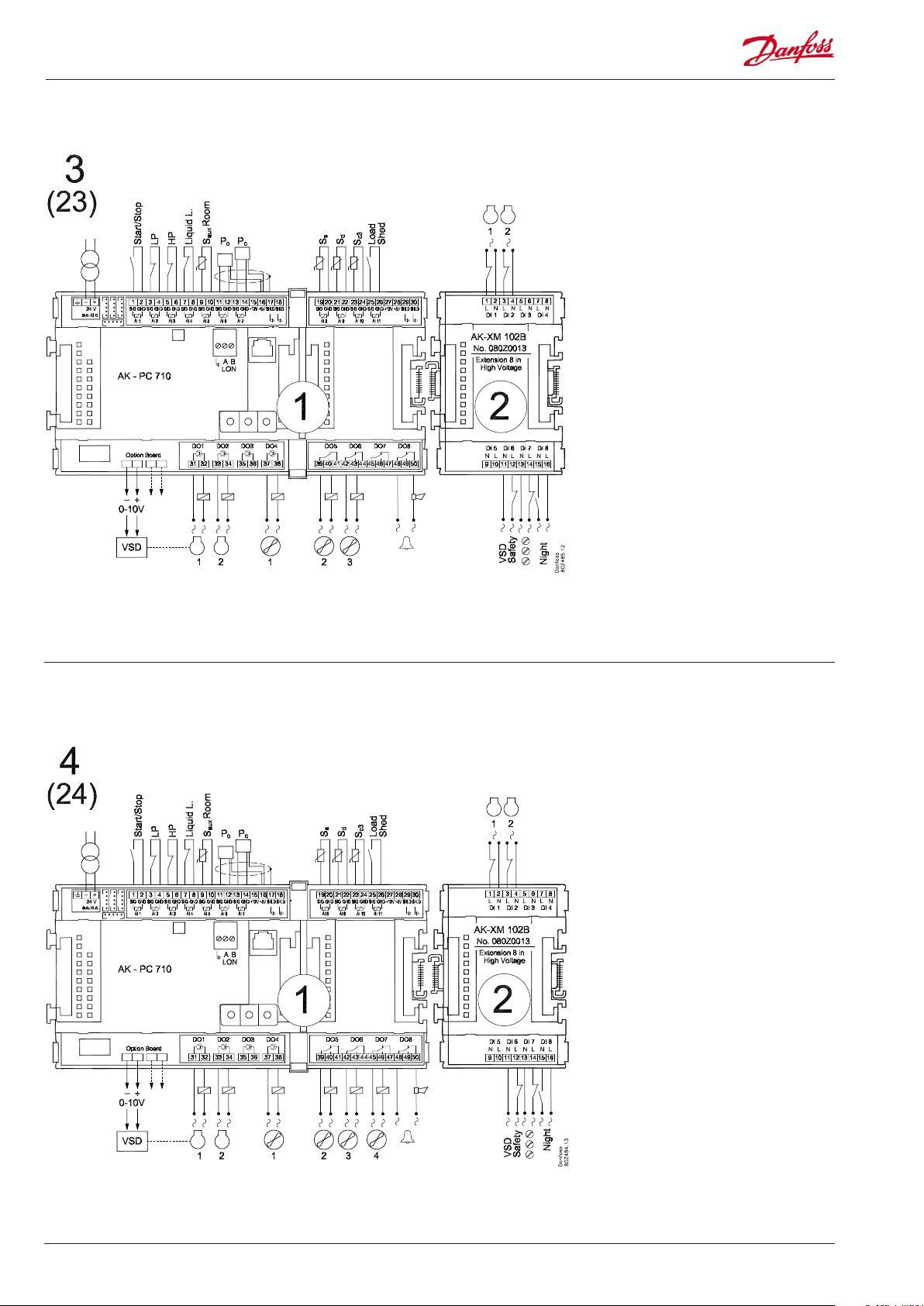
Application 3 and 23 (for 23 leave out the VSD connection on the option board)
1
Application 4 and 24 (for 24 leave out the VSD connection on the option board)
24 Capacity controller RS8FT502 © Danfoss 08-2015 AK-PC 710
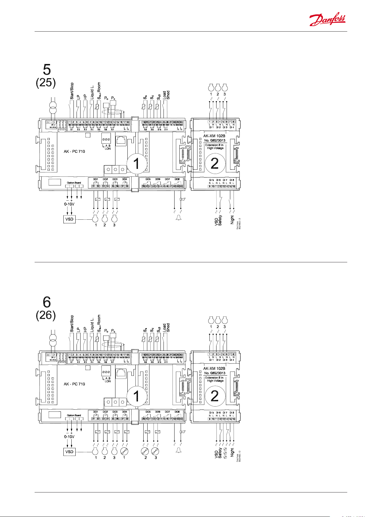
Application 5 and 25 (for 25 leave out the VSD connection on the option board)
Application 6 and 26 (for 26 leave out the VSD connection on the option board)
AK-PC 710 Capacity controller RS8FT502 © Danfoss 08-2015 25
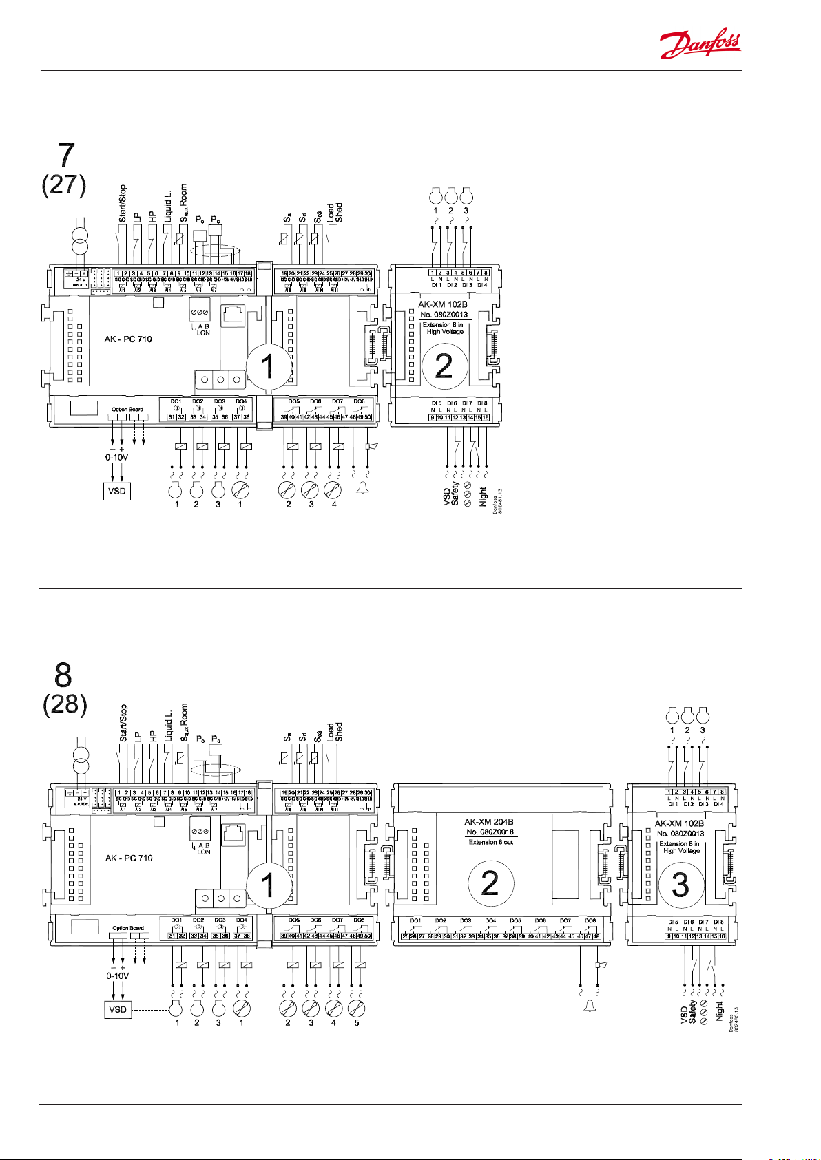
Application 7 and 27 (for 27 leave out the VSD connection on the option board)
Application 8 and 28 (for 28 leave out the VSD connection on the option board)
26 Capacity controller RS8FT502 © Danfoss 08-2015 AK-PC 710
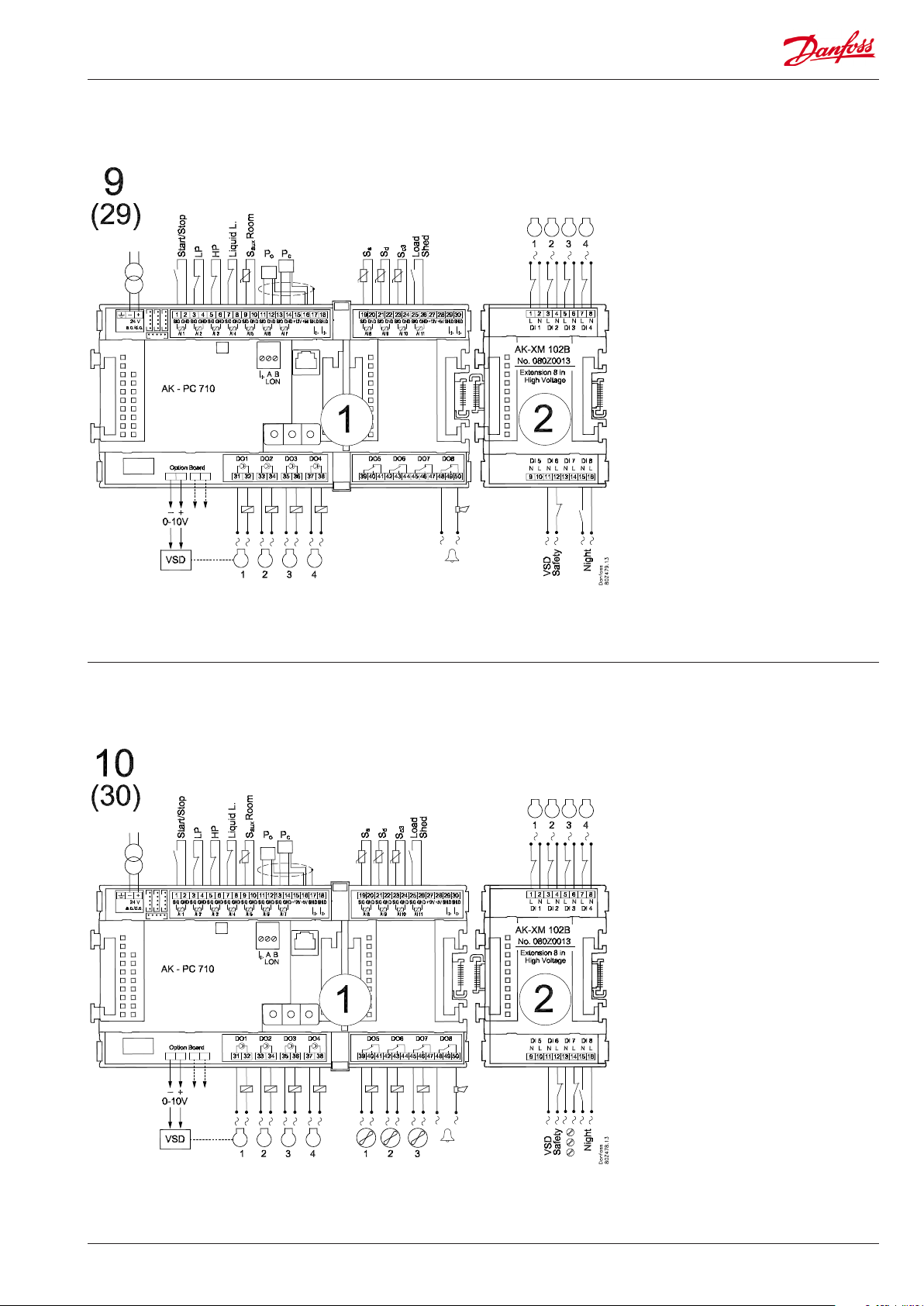
Application 9 and 29 (for 29 leave out the VSD connection on the option board)
Application 10 and 30 (for 30 leave out the VSD connection on the option board)
AK-PC 710 Capacity controller RS8FT502 © Danfoss 08-2015 27
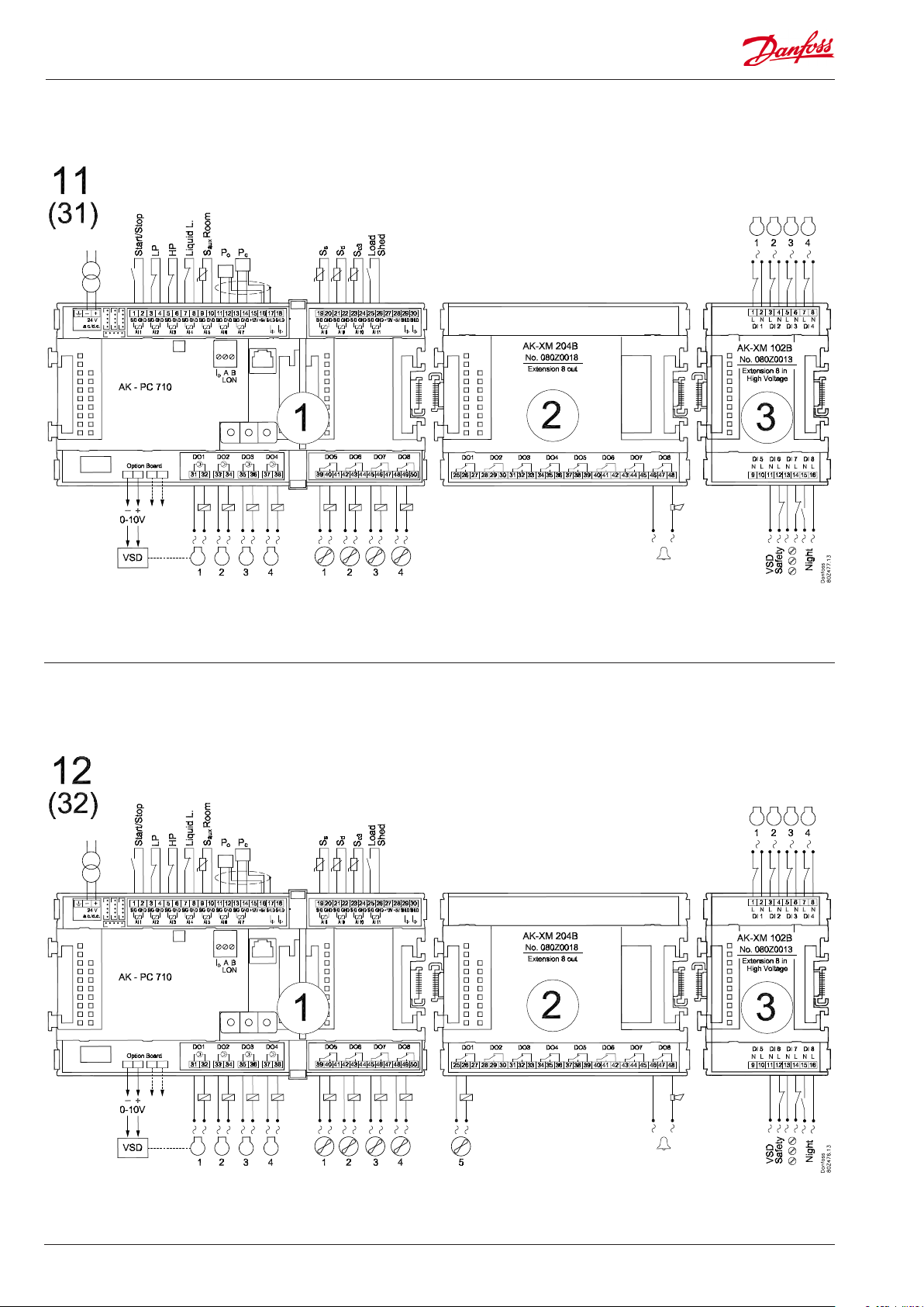
Application 11 and 31 (for 31 leave out the VSD connection on the option board)
Application 12 and 32 (for 32 leave out the VSD connection on the option board)
28 Capacity controller RS8FT502 © Danfoss 08-2015 AK-PC 710

Application 13 and 33 (for 33 leave out the VSD connection on the option board)
Application 14 and 34 (for 34 leave out the VSD connection on the option board)
AK-PC 710 Capacity controller RS8FT502 © Danfoss 08-2015 29

Application 15 and 35 (for 35 leave out the VSD connection on the option board)
Application 16 and 36 (for 36 leave out the VSD connection on the option board)
30 Capacity controller RS8FT502 © Danfoss 08-2015 AK-PC 710

Application 17 and 37 (for 37 leave out the VSD connection on the option board)
Application 18 and 38 (for 38 leave out the VSD connection on the option board)
AK-PC 710 Capacity controller RS8FT502 © Danfoss 08-2015 31

Application 19 and 39 (for 39 leave out the VSD connection on the option board)
Application 20 and 40 (for 40 leave out the VSD connection on the option board)
32 Capacity controller RS8FT502 © Danfoss 08-2015 AK-PC 710

Ordering
1. Controller
Type Function Language Code no.
AK-PC 710 Controller for capacity control of up to 6 compressors and up to 6 condenser fans
2. Extension modules and survey for inputs and outputs
Type Analog
inputs
For sensors,
pressure
transmitters
etc.
Controller 11 4 4 - - - - -
Extension modules
AK-XM 102A 8 080Z0008
AK-XM 102B 8 080Z0013
AK-XM 204A 8 080Z0011
AK-XM 204B 8 x 080Z0018
AK-OB 110 2 080Z0251
On/O outputs On/o supply voltage
Relay
(SPDT)
Solid state Low voltage
(DI signal)
(max. 80 V)
High voltage
(max. 260 V)
English, German, French,
Dutch, Italian, Spanish
Analog
outputs
0-10 V d.c. For override
Module with
switches
of relay
outputs
080Z0106
Code no.
With screw
terminals
3. AK operation and accessories
Type Function Application Code no.
Operation
AK-ST 500 Software for operation of AK controllers AK-operation 080Z0161
- Cable between PC and AK controller AK - Com port 080Z0262
-
Accessories Power supply module 230 V / 115 V to 24 V
AK-PS 075 18 VA Supply for controller 080Z0053
Accessories External display that can be connected to the controller module. For showing, say, the suction pressure
EKA 163B Display 084B8574
EKA 164B Display with operation buttons 084B8575
EKA 166 Display with operation buttons and LED's for inputs and outputs 084B8578
AK-MMI Graphic display with operation 080G0311
- Cable between EKA display and controller
- Cable between graphic display and controller
Cable between zero modem cable and AK controller /
Cable between PDA cable and AK controller
Cable between PC and AK controller AK - USB 080Z0264
AK - RS 232 080Z0261
Length = 2 m 084B7298
Length = 6 m 084B7299
Length = 0.8 m 080G0074
Length = 1.5 m 080G0075
Length = 3 m 080G0076
Accessories Real time clock for use in controllers that require a clock function, but are not wired with data communication.
AK-OB 101A Real time clock with battery backup. To be mounted in an AK controller 080Z0252
AK-PC 710 Capacity controller RS8FT502 © Danfoss 08-2015 33

34 Capacity controller RS8FT502 © Danfoss 08-2015 AK-PC 710

3. Mounting and wiring
This section describes how the controller:
• Is tted
• Is connected
AK-PC 710 Capacity controller RS8FT502 © Danfoss 08-2015 35

Mounting and wiring - continued
Mounting
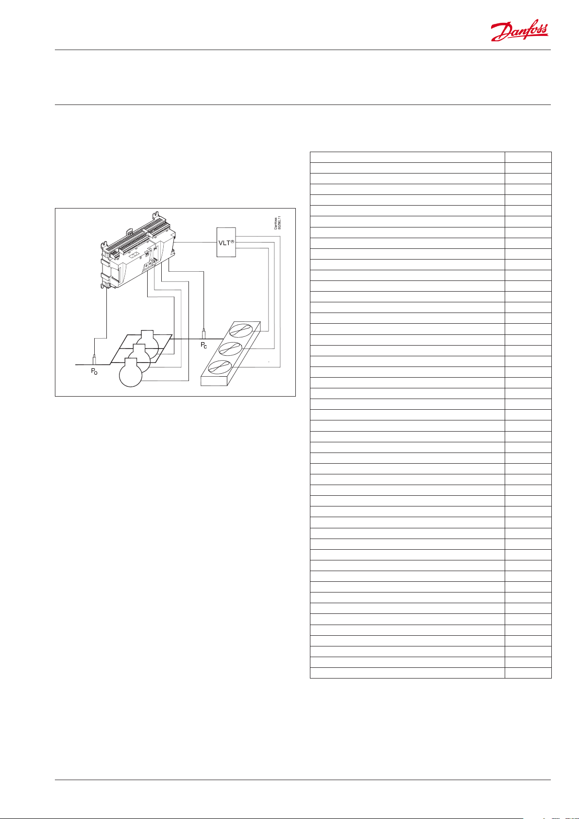
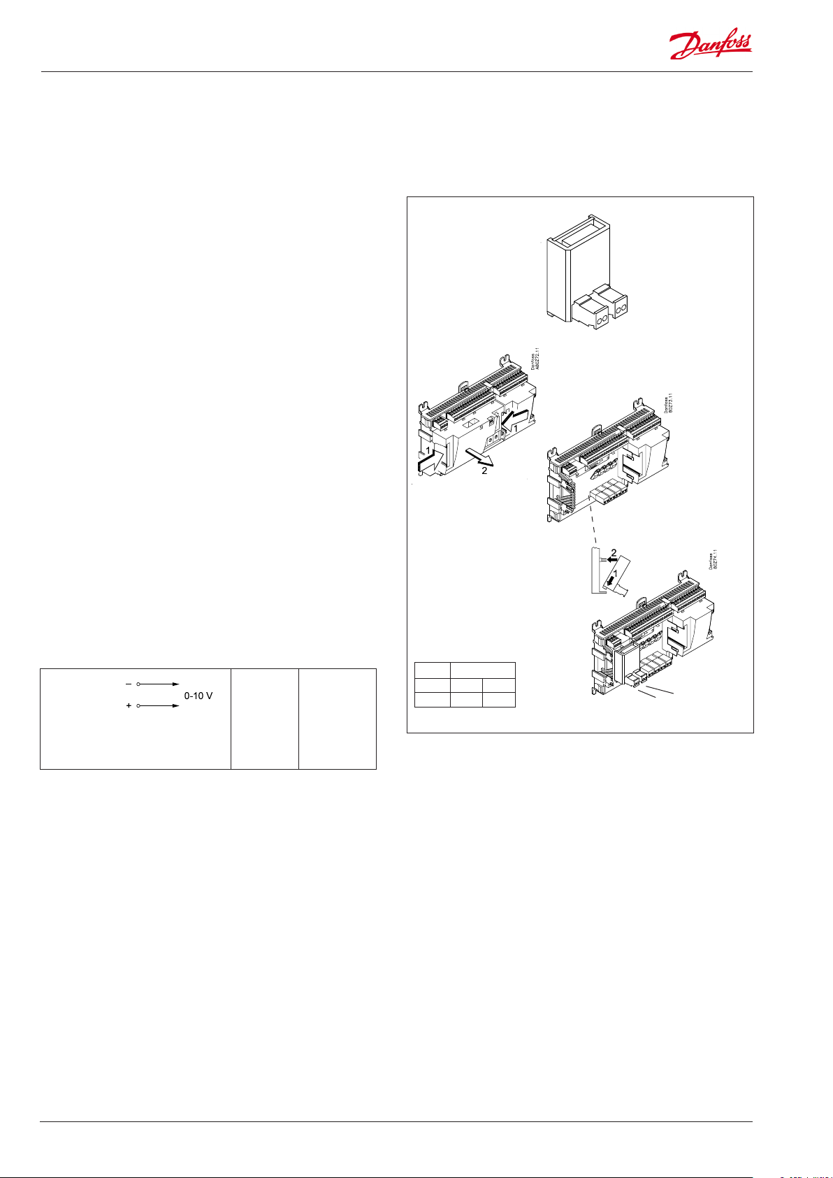
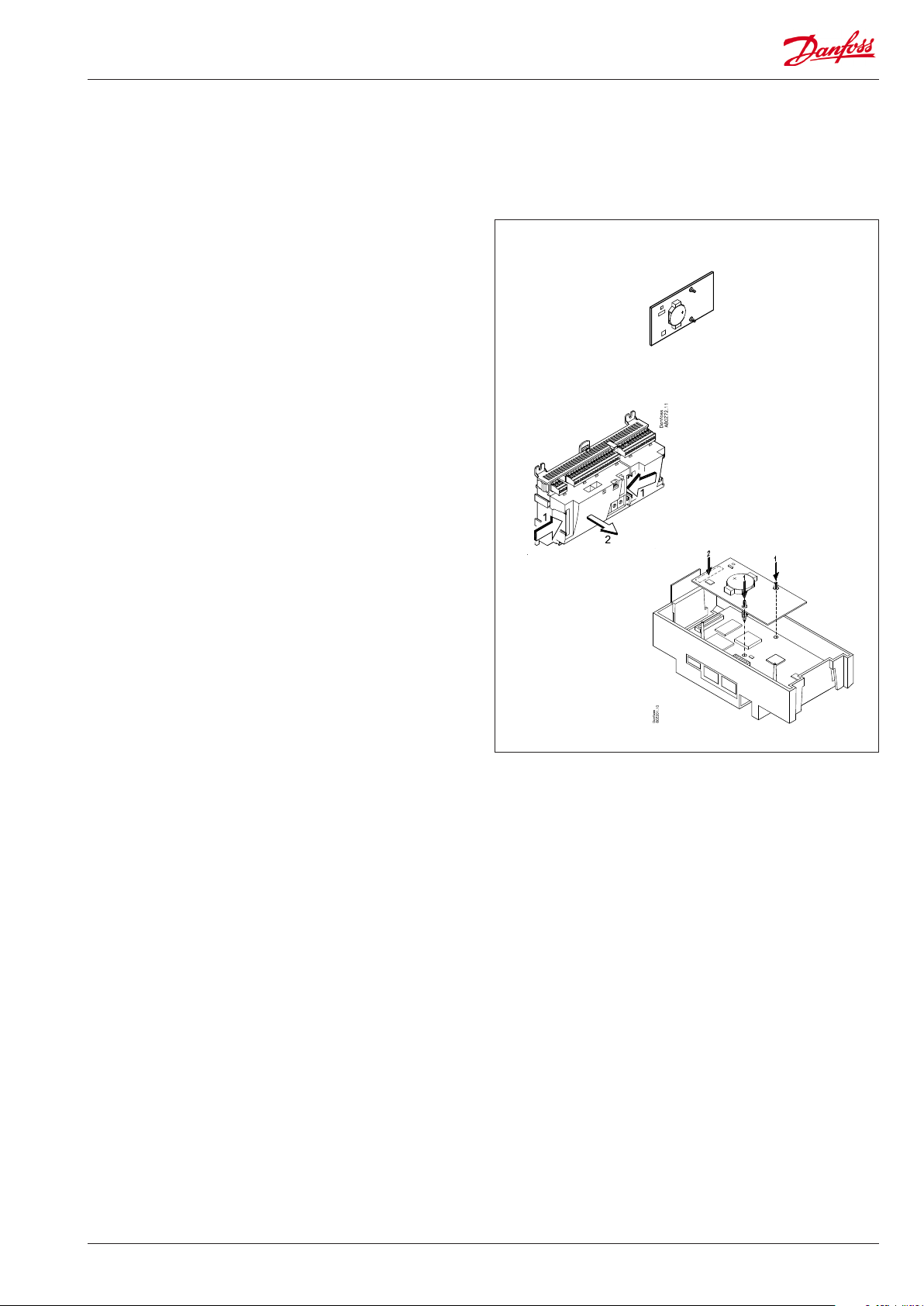
Mounting of analog output module
1. Lift the top part o the basic module
The basic module must not be connected to voltage.
Press in the plate on the left-hand side of the light-emitting
diodes and the plate on the right-hand side for the red address
changers.
Lift the top part o the basic module.
The analog extension module will supply a signal to the variable frequency drive.
2. Mount the extension module in the basic module
3. Put the top part back on the basic module
36 Capacity controller RS8FT502 © Danfoss 08-2015 AK-PC 710

Mounting and wiring - continued
Mounting of extension module on the
basic module
1. Move the protective cap
Remove the protective cap from the connection plug on the
right-hand side of the basic module.
Place the cap on the connection plug to the right of the extension module that is to be mounted on the extreme right-hand
side of the AK assembly.
2. Assemble the extension module and the basic
module
The basic module must not be connected to voltage.
When the two snap catches for the DIN rail mounting are in the open
position, the module can be pushed into place on the DIN rail – regardless of where the module is on the row.
Disassembly is thus done with the two snap catches in the open position.
The sequence is determined by the shown electrical diagram
AK-PC 710 Capacity controller RS8FT502 © Danfoss 08-2015 37

Mounting and wiring - continued
Wiring
Decide during planning which function is to be connected and
where this will be.
1. Connect inputs and outputs
See the earlier selected electrical diagram:
2. Connect LON communication network
The installation of the data communication must comply with
the requirements set out in document RC8AC.
3. Connect supply voltage
Is 24 V, and the supply must not be used by other controllers or
devices. The terminals must not be earthed.
4. Follow light-emitting diodes
When the supply voltage is connected the controller will go
through an internal check. The controller will be ready in just
under one minute when the light-emitting diode ”Status” starts
ashing slowly.
5. When there is a network
Set the address and activate the Service Pin.
6. The controller is now ready to be congured.
Example
The screen on the pressure transmitter
cables must only be connected at the
end of the controller.
Internal communication
between the modules:
Quick ash = error
Constantly On = error
■ Power
■ Comm
■ DO1 ■ Status
■ DO2 ■ Service Tool
■ DO3 ■ LON
■ DO4
■ DO5 ■ Alarm
■ DO6
■ DO7
■ DO8 ■ Service Pin
Status on output 1-8
Slow ash = OK
Quick ash = answer from gateway
in 10 min. after network
installation
Constantly ON = error
Constantly OFF = error
External communication
Flash = active alarm/not cancelled
Constant ON = Active alarm/cancelled
Network installation
Warning
Keep signal cables separate from
cables with high voltage.
38 Capacity controller RS8FT502 © Danfoss 08-2015 AK-PC 710

4. Conguration and operation
This section describes how the controller:
• Is congured
• Is operated
We have decided to work on the basis of application no. 16, i.e.
compressor control with 5 compressors and condenser control
with 6 fans.
The example is shown overleaf.
AK-PC 710 Capacity controller RS8FT502 © Danfoss 08-2015 39

Refrigerating plant example
We have decided to describe the setup by means of an example
comprising a compressor group and a condenser.
The example is the same as the one given in the "Application no.
16", i.e. the controller is an AK-PC 710 + 3 extension modules.
Compressor pack:
• Refrigerant R134a
• 1 only speed-regulated compressor (30 kW, 30-60 Hz)
• 4 only compressors (15 kW) with working-hour equalisation
• Safety monitoring of each compressor
• Common high-pressure monitoring
• Common low-pressure monitoring
• Po setting -15°C, night displacement 5 K
Condenser:
• 6 fans, step regulation
• Pc regulates based on outdoor temperature Sc3
Receiver:
• Monitoring of liquid level in receiver
Plant room
• Monitoring of temperature in plant room
Safety functions:
• Monitoring of Po, Pc, Sd and superheat on suction line
• Po max = -5°C, Po min = -35°C
• Pc max = 50 °C
• Sd max = 120°C
• SH min = 5 °C, SH max = 35 °C
Other:
• Alarm output used
• External main switch used
• Monitoring of frequency converter (VSD)
For the example shown we use the following modules:
• AK-PC 710 basic module
• AK-XM 204B relay module
• AK-XM 102B digital input module
• AK-OB 110 analog output module
NB!
The capacity of the compressor with speed adjustment should be
greater than that of the other compressors.
This ensures that there are no "gaps" in the cut in capacity.
See chapter 5, Adjustment functions.
There is also an internal main switch as a setting. Both must be “ON”
before any adjustment is made.
The used modules is selected in the Design phase.
40 Capacity controller RS8FT502 © Danfoss 08-2015 AK-PC 710

Conguration via service tool
AK-ST 500
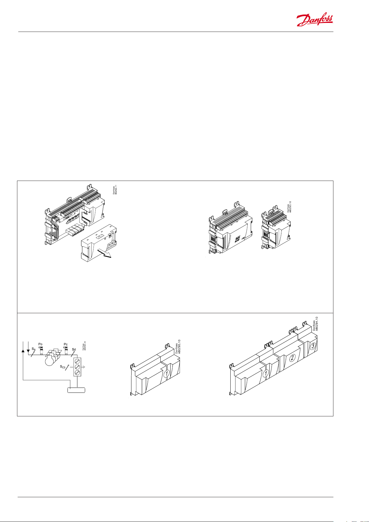
Connect PC
PC with the program “Service Tool” is connected to the controller.
The controller must be switched on rst and the LED “Status” must
ash before the Service Tool programme is started.
Start Service Tool programme
For connecting and operating the "AK service tool" software,
please see the manual for the software.
The rst time the Service Tool is connected to a new version of a controller the start-up of the Service Tool will take longer than usual while
information is retrieved from the controller.
Time can be followed on the bar at the bottom of the display.
Login with user name SUPV
Select the name SUPV and key in the access code.
When the controller is supplied the SUPV access code is 123.
When you are logged into the controller an overview of it will always
appear.
In this case the overview is empty. This is because the controller has not
yet been set up.
The red alarm bell at the bottom right tells you that there is an active
alarm in the controller. In our case the alarm is due to the fact that the
time in the controller has not yet been set.
AK-PC 710 Capacity controller RS8FT502 © Danfoss 08-2015 41

Conguration - continued
Authorization
1. Go to Conguration menu
Press the orange setup button with the spanner at the bottom
of the display.
2. Select Authorization
3. Change setting for the user ‘SUPV‘
When the controller is supplied it has been set with standard authorization for dierent user interfaces. This setting should be changed and
adapted to the plant. The changes can be made now or later.
You will use this button again and again whenever you want to get to
this display.
On the left-hand side are all the functions not shown yet. There will be
more here the further into the setup we go.
Press the line Authorization to get to the user setup display.
4. Select username and access code
5. Carry out a new login with the user name and the
new access code
Mark the line with the user name SUPV.
Press the button Change
This is where you can select the supervisor for the specic system and a
corresponding access code for this person.
In earlier versions of the service tool AK-ST 500 it was possible to select
the language in this menu.
An updated version of the service tool will be released in the spring of
2009. If the controller is operated with the new version, language selection will happen automatically in connection with the conguration of
the service tool.
The controller will utilize the same language that is selected in the
service tool but only if the controller contains this language. If the
language is not contained in the controller, the settings and readings
will be shown in English.
To activate the new settings you must carry out a new login to the controller with the new user name and the relevant access code.
You will access the login display by pressing the padlock at the top left
corner of the display.
42 Capacity controller RS8FT502 © Danfoss 08-2015 AK-PC 710

Conguration - continued
Unlock the conguration of the
controllers
1. Go to Conguration menu
2. Select Lock/Unlock conguration
The controller can only be congured when it is unlocked.
The values can be changed when it is locked, but only for those settings
that do not aect the conguration.
3. Select Conguration lock
Press the blue eld with the text Locked
4. Select Unlocked
Select Unlocked and press OK.
AK-PC 710 Capacity controller RS8FT502 © Danfoss 08-2015 43

Conguration - continued
System setup
1. Go to Conguration menu
2. Select System setup
3. Set system settings
All system settings can be changed by pressing in the blue eld with the
setting and then indicating the value of the required setting.
In the rst eld you enter a name for what the controller will be controlling.
When the time is set the PC’s time can be transferred to the controller.
When the controller is connected to a network, date and time will
automatically be set by the system unit in the network. This also applies
to change-over Daylight saving.
If the controller is installed in a network, "automatic acknowledgement
of alarms" should be set to "disable" - Hereby the alarm processing and
acknowledgement is transferred to the system unit.
If the controller is installed without a network, "automatic acknowledgement of alarms" should be set to "enable" - Hereby the controller
acknowledges the alarms itself.
44 Capacity controller RS8FT502 © Danfoss 08-2015 AK-PC 710

Conguration - continued
Set plant type
1. Go to Conguration menu
2. Select plant type
Press the line Select plant type.
3. Set plant type
This setting refers to applications. See page 22.
After conguration of this function, the controller will shut down
and restart. After the restart, a large number of settings will have
been made. These include the connection points. Continue with the
settings and check the values. If you change some of the settings,
the new values will.
AK-PC 710 Capacity controller RS8FT502 © Danfoss 08-2015 45

Conguration - continued
Set control of compressors
1. Go to Conguration menu
2. Select Suction group
3. Set values for the reference
Press the +-button to go on to the
next page
4. Set values for capacity control
The conguration menu in the Service
Tool has changed now. It shows the pos-
sible settings for the selected plant type.
In our example we select the settings:
- Suction set point = -15°C
- Night oset value = 5 K.
The settings are shown here in the display.
There are several pages, one after the
other.
The black bar in this eld tells you which
of the pages is currently displayed.
Move between the pages using the +
and - buttons.
In our example we select:
- Refrigerant = R134a
- Equalisation of working hours
- Value for speed regulation
Speed regulation can always only be on
compressor number 1.
The settings are shown here in the
display.
Not all compressors can have their speed
adjusted. If there is any doubt, contact your
compressor supplier.
If you want to know more about the dierent conguration options, they are listed below.
The number refers to the number and picture in the
column on the left.
The screen only shows the settings and readings that
are required for a given set-up.
3 - Po-Reference
Reference = set reference + night oset + oset
from P0 optimization
Setpoint ( -80 to +30°C)
Setting of required suction pressure in °C
Night Oset (-25 to +25 K)
Displacement value for suction pressure in connection with an active night setback signal (set in
Kelvin)
Changing to night-time operation can be carried
out with a signal sent via the data communication,
with a signal on the input "night" or via the weekly
schedule in the controller.
Max reference (-50 to +80 °C)
Max. permissible suction pressure reference
Min reference (-80 to +25 °C)
Min. permissible suction pressure reference
4 - Compressor application
Po refrigerant type
Select refrigerant type
Po refrigerant factors K1, K2, K3
Only used if “Po refrigerant type” is set to custom
(contact Danfoss for information)
Step control mode
Select coupling pattern for compressors
Sequential: Compressors are cut in/out in strict accordance with compressor number (FILO)
Cyclic: Runtime equalisation between compressors
(FIFO) (same sized compressors)
Best t: Compressors are cut in/out in order to
make the best possible t to actual load (dierent
sized compressors)
Pump down
Select whether a pump down function is required
on the last running compressor
Pump down limit (-80 to +30 °C)
Set the actual pump down limit for the last compressor
VSD min speed (0.5 – 60.0 Hz)
Min. speed where the compressor must cutout
VSD start speed (20.0 – 60.0 Hz)
Minimum speed for start of Variable speed drive
(Must be set higher than “VSD Min. Speed Hz”)
VSD max speed (40.0 – 120.0 Hz)
Highest permissible speed for the compressor
motor
Load shed limit
Set max capacity limit for load shed Load Shed"
Override limit Po
If the P0 exceeds the value, a time delay is started. If
the time delay runs out, the load limit is cancelled
Override delay
Max. time for capacity limit, if P0 is too high
Kp Po (0.1 – 10.0)
Amplication factor for P0 regulation
Advanced control settings
Select whether the adv. settings must be visible
Min. capacity change (0 – 100 %)
Set the minimum capacity change needed before
the capacity distributor connects or disconnects
compressors
Minimize cycling
The control zone may vary for connections and
disconnections. See Section 5.
Initial start time (15 – 900 s)
The time after start-up where the cut-in capacity is
limited to the rst compressor step.
46 Capacity controller RS8FT502 © Danfoss 08-2015 AK-PC 710

Conguration - continued
Press the +-button to go on to the
next page
5. Set values for capacity of the
compressors
Press the +-button to go on to the
next page
6. Set values for safe operation
Press the +-button to go on to the
next page
In our example we select:
- Speed-controlled compressor
of 30 kW (compressor 1)
- Four compressors of 25 kW
The example settings are shown
here in the display.
(For cyclic operation, all one-step
compressors have the same size.
This is why there is only one setting, but it covers all 4.)
In our example we select:
- Safety limit for discharge
temperature = 120°C
- Safety limit for high condensing
pressure = 50°C
- Safety limit for low suction
pressure = -35°C
- Alarm limit for high suction
pressure = -5°C
- Alarm limit for min. and max.
superheat, respectively = 5 and
35 K.
5 - Compressors
In this screen the capacity distribution between the compressors is dened.
Capacities that need to be set depend upon the “compressor
application” and “Step control mode” that has been selected.
Nominal capacity (0.0 – 99.9 kW)
Set the nominal capacity for the compressor in question.
For compressors with variable speed drive the nominal
capacity must be set for the mains frequency (50/60 Hz)
6 - Safety
Delay time for liquid level alarm
Set the delay time (from the time the signal is lost on the
input to the time when the alarm is sent)
Delay time for VSD-alarm
Set the delay time
Temperature alarm limit
Set the threshold value for the temperature alarm
Delay time for the temperature alarm
Set the delay time
Emergency cap. day
The desired cut-in capacity for daily use in the case of emergency operations resulting from error in the suction pressure
sensor/ media temperature sensor.
Emergency cap. night
The desired cut-in capacity for night operations in the case
of emergency operations resulting from error in the suction
pressure sensor/ media temperature sensor.
Sd max limit
Max. value for discharge gas temperature
10 K below the limit, the compressor capacity should be
reduced and the entire condenser capacity will be cutin.
If the limit is exceeded, the entire compressor capacity will
be cutout
Pc Max limit
Maximum value for the condenser pressure in °C
3 K below the limit, the entire condenser capacity will be
cutin and the compressor capacity reduced.
If the limit is exceeded, the entire compressor capacity will
be cutout.
Pc Max delay
Time delay for the alarm Pc max
P0 Min limit
Minimum value for the suction pressure in °C
If the limit is reduced, the entire compressor capacity will be
cutout.
P0 Max alarm
Alarm limit for high suction pressure P0
P0 Max delay
Time delay before alarm for high suction pressure P0.
Safety restart time
Common time delay before restarting the compressor.
(Applicable to the functions: "Sd max. limit", Pc max. limit"
and "P0 min. limit).
SH Min alarm
Alarm limit for min. superheat in suction line.
SH Max alarm
Alarm limit for max. superheat in suction line.
SH alarm delay
Time delay before alarm for min./max. superheat in suction
line.
AK-PC 710 Capacity controller RS8FT502 © Danfoss 08-2015 47

Conguration - continued
7. Set operation time for compressor
Press the +-button to go on to the
next page
8. Set times for safety cutouts
Set min. OFF-time for the compressor relay
Set min. ON-time for the compressor relay
Set how often the compressor is
allowed to start
If the restrictions overlap, the
controller will use the longest
restriction time.
7 - Minimum operation times
Congure the operation times here so "unnecessary operation" can be avoided.
Min. OFF time
The time the compressor should be idle before it should start
again.
Min. ON time
The time the compressor should operate before it should
stop.
Restart time
The lowest time interval between two consecutive starts.
8 - Safety timer
Cutout delay
The time delay resulting from drop-out of automated safety
measures and until the compressor-error is reported.
Restart delay
Minimum time that a compressor should be OK after a safety
cut-out. After this interval it can start again.
(An alarm which is triggered by the automatic safety function
will be maintained until the restart delay has expired.)
48 Capacity controller RS8FT502 © Danfoss 08-2015 AK-PC 710

Conguration - continued
Setup control of condenser
1. Go to Conguration menu
2. Select Condenser
3. Set control mode and reference
In our example the condenser
pressure is controlled on the
basis of the outdoor temperature
(oating reference).
The settings shown here in the
display.
3 - PC reference
Reference Mode
Choice of condenser pressure reference
Fixed setting: Used if a permanent reference is required =
“Setting”
Floating: Used if the reference is changed as a function of Sc3
the external temperature signal, the congured "Dimensioning tm K"/"Minimum tm K" and the actual cut in compressor
capacity.
Setpoint
Setting of desired condensing pressure in °C. It should also be
set when oating references are used. The value is used as a
reference if the Sc3 sensor becomes defective.
Min. tm
Minimum average temperature dierence between Sc3 air
and Pc condensing temperature when no compressors are in
operation.
Dimensioning tm
Dimensioning average temperature dierential between Sc3
air and Pc condensing temperature at maximum load (tm
dierence at max load, typically 8-15 K).
Min reference
Min. permitted condenser pressure reference
Max reference
Max. permitted condenser pressure reference
Press the +-button to go on to the
next page
4. Set values for capacity regulation
Used in our example are six stepcontrolled fans.
The settings shown here in the
display.
4 - Capacity control
Capacity control mode
Select control mode for condenser
Step: Fans are step-connected via relay outputs
Step/speed: The fan capacity is controlled via a combination
of speed control and step coupling
Speed: The fan capacity is controlled via speed control (frequency converter)
Control type
Choice of control strategy
P-band: The fan capacity is regulated via P-band control. The
P band is congured as "Proportional band Xp"
PI-Control: The fan capacity is regulated by the PI controller.
Capacity curve
Choice of capacity curve type
Linear: The same amplication in the entire area
Square: Square curve shape, which gives higher amplication
at higher loads.
VSD start speed
Minimum speed for start of speed control (Must be congured higher than "VSD Min. Speed %")
VSD min Speed
Minimum speed whereby speed control is cut-out (low load).
Proportional band Xp
Proportional band for P/PI controller
Integration time Tn
Integration time for PI controller
AK-PC 710 Capacity controller RS8FT502 © Danfoss 08-2015 49

Conguration - continued
Conguration of inputs
and outputs
1. Go to Conguration menu
2. Select I/O conguration
3. Conguration of Digital outputs
Press the +-button to go on to the
next page
4. Setup On/o input functions
The outputs are enabled by On (relay activated)
!!! The alarm is inverted so that there will be an alarm if the supply
voltage to the controller fails.
Select for each input whether the function is to be active when the
input is in pos. Closed or Open.
Open has been selected here for all the safety circuits. This means
that the controller will receive signal under normal operation and
register it as a fault if the signal is interrupted.
Press the +-button to go on to the
next page
50 Capacity controller RS8FT502 © Danfoss 08-2015 AK-PC 710

Conguration - continued
5. Conguration of Analog
outputs
Press the +-button to go on to
the next page
6. Conguration of Analog
Input signals
We set up the analog outputs for control of the compressor speed.
We set up the analog inputs for the sensors.
5 - Analog outputs
The possible signals are
the following:
0 -10 V
2 – 10 V
0 - 5 V
1 – 5V
6 - Analog inputs
The possible signals are
the following:
Temperature sensors:
• Pt1000
• PTC 1000
Pressure transmitters:
• AKS 32, -1 – 6 Bar
• AKS 32R, -1 – 6 Bar
• AKS 32, - 1 – 9 Bar
• AKS 32R, -1 – 9 Bar3
• AKS 32, - 1 – 12 Bar
• AKS 32R, -1 – 12 Bar
• AKS 32, - 1 – 20 Bar
• AKS 32R, -1 – 20 Bar
• AKS 32, - 1 – 34 Bar
• AKS 32R, -1 – 34 Bar
• AKS 32, - 1 – 50 Bar
• AKS 32R, -1 – 50 Bar
• AKS 2050, -1 – 59 Bar
• AKS 2050, -1 – 99 Bar
• AKS 2050, -1 – 159 Bar
• Customised ratiometric
application: Here, the
transmitters min. and
max. pressure areas are
set (relative pressure
reading)
AK-PC 710 Capacity controller RS8FT502 © Danfoss 08-2015 51

Conguration - continued
Set alarm priorities
1. Go to Conguration menu
2. Select Alarm priorities
3. Set priorities for Suction group
Very many functions have an alarm connected.
Your choice of functions and settings has connected all the relevant
alarms that are current. They will be shown with text in the three
pictures.
All alarms that can occur can be set for a given order of priority:
• ”High” is the most important one
• ”Log only” has lowest priority
• ”Disconnected” gives no action
The interdependence between setting and action can be seen in the
table.
Setting
High X X X 1
Medium X X 2
Low X X 3
Log only X 4
Disconnected
In our example we select the settings shown here in the display
Log Alarm relay Network AKM- dest.
Press the +-button to go on to the next page
4. Set alarm priorities for condenser
In our example we select the settings shown here in the display
Press the +-button to go on to the next page
52 Capacity controller RS8FT502 © Danfoss 08-2015 AK-PC 710

Conguration - continued
5. Set alarm priorities for
temperature alarm and Digital signals
In our example we select the settings shown here in the display
AK-PC 710 Capacity controller RS8FT502 © Danfoss 08-2015 53

Conguration - continued
Lock conguration
1. Go to Conguration menu
2. Select Lock/Unlock conguration
3. Lock Conguration
Press in the eld against Conguration lock.
Select Locked.
Press OK.
The setup of the controller has now been locked. If you subsequently
want to make any changes in the controller’s setup, remember rst to
unlock the conguration.
The controller will now make a comparison of selected functions and dene inputs and outputs. The result can be seen in
the next section where the setup is controlled.
54 Capacity controller RS8FT502 © Danfoss 08-2015 AK-PC 710

Conguration - continued
Check conguration
1. Go to Conguration menu
2. Select I/O conguration
3. Check conguration of Digital Outputs
This control requires that the setup is locked
(Only when the setup is locked are all settings for in- and outputs activated.)
An error has occurred, if you see the
following:
A 0 – 0 next to a dened function.
If a setting has reverted to 0-0, you must control
the setup again.
Press the +-button to go on to the next page
4. Check conguration of Digital Inputs
Press the +-button to go on to the next page
The error is caused by the two modules connected
to the controller being switched.
AK-PC 710 Capacity controller RS8FT502 © Danfoss 08-2015 55

Conguration - continued
5. Check conguration of Analog Outputs
Press the +-button to go on to the next page
6. Check conguration of Analog Inputs
(If no speed control of the condenser fans is used, the module and point
number can be 0 -0.)
56 Capacity controller RS8FT502 © Danfoss 08-2015 AK-PC 710

Check of connections
1.Go to Conguration menu
2. Select I/O status and manual
Before the control is started we check that all inputs and outputs have
been connected as expected.
This controls requires that the setup is locked
3. Check Digital Outputs
Press the +-button to go on to the next page
4. Check Digital Inputs
By means of the manual control of each output it can be checked
whether the output has been correctly connected.
AUTO The output is controlled by the controller
MAN OFF The output is forced to pos. OFF
MAN ON The output is forced to pos ON
Cut out the safety circuit for compressor 1.
Check that LED DI1 on the extension module (module 3) goes out.
Check that the value of the alarm for the safety monitoring of compressor 1 changes to ON.
The remaining digital inputs are checked in the same way.
Press the +-button to go on to the next page
AK-PC 710 Capacity controller RS8FT502 © Danfoss 08-2015 57

Check of connections - continued
5. Check Analog outputs
Set Control of output voltage to manual
Press in the Mode eld.
Select MAN.
Press OK.
Press in the Value eld
Select for example 50%.
Press OK.
On the output you can now measure the expected value: In this
example 5 volts
6. Put the control of the output voltage back to automatic
Press the +-button to go on to the next page
7. Check Analog inputs
Example of the connection between a dened output signal
and a manual set value.
Denition Setting
0 % 50 % 100 %
0 - 10 V 0 V 5 V 10 V
1 - 10 V 1 V 5.5 V 10 V
0 - 5 V 0 V 2.5 V 5 V
2 - 5 V 2 V 3.5 V 5 V
Check that all sensors show sensible values.
In our case we have no value for the suction gas temperature Ss and
the two sensors. This may be due to the following:
• The sensor has not been connected.
• The sensor is short-circuited.
• The point or module number has not been set up correctly.
• The conguration is not locked.
58 Capacity controller RS8FT502 © Danfoss 08-2015 AK-PC 710

Check of settings
1.Go to the overview
2. Select suction group
Before the control starts, we check that all the settings are as they should
be.
The overview display will now show one line for each of the general
functions. Behind each icon there is a number of displays with the
dierent settings. It is all these settings that have to be checked.
3. Move on through all the individual displays for the
suction group
Change displays with the +- button. Remember the settings at
the bottom of the pages – the ones that can only be seen via
the ”Scroll bar”.
4. Safety limits
5. Go back to the overview
The last page contains safety limits and restart times.
6. Select condenser group
AK-PC 710 Capacity controller RS8FT502 © Danfoss 08-2015 59

Check of settings - continued
7. Move on through all the individual displays for the
condenser group.
Change displays with the +- button. Remember the settings at
the bottom of the pages – the ones that can only be seen via
the ”Scroll bar”.
8. Safety limits
9. The controller setup has been completed.
The last page contains safety limits and restart times.
60 Capacity controller RS8FT502 © Danfoss 08-2015 AK-PC 710

Schedule function
1. Go to Conguration menu
2. Select schedule
3. Setup schedule
For your information
This setting is not necessary in the example. The signal comes in via DI8.
In other cases where the controller is installed in a network with one
system unit, this setting may be made in the system unit which will then
transmit a day/night signal to the controller.
This setting can only be used, if the controller stands alone and is tted
with a clock module.
Press a weekday and set the time for the day period.
Continue with the other days.
A complete weekly sequence is shown in the display.
AK-PC 710 Capacity controller RS8FT502 © Danfoss 08-2015 61

Installation in network
1. Set the address (here, for example 3)
Turn the right-hand address switch so that the arrow will point
at 3.
The arrow of the two other address switches must point at 0.
2. Push the Service Pin
Press down the service pin and keep it down until the Service
Pin LED lights up.
The controller has to be remote-monitored via a network. In this net-
work we assign address number 3 to the controller.
The same address must not be used by more than one controller in the
same network.
Requirement to the system unit
The system unit must be a gateway type AKA 245 with software version
6.0 or higher. It is capable of handling up to 119 AK controllers.
3. Wait for answer from the system unit
Depending on the size of the network it may be up to one
minute before the controller receives an answer as to whether
it has been installed in the network.
When it has been installed the Status LED will start to ash
faster than normal (once every half second). It will continue
with this for about 10 minutes
4. Carry out new login via Service Tool
If the Service Tool was connected to the controller while you
installed it in the network, you must carry out a new login to
the controller via the Service Tool.
Alternatively, it can be an AK-SM 720. It is capable of handling up to 200
AK controllers.
If there is no answer from the system unit
If the Status LED does not start ashing faster than normal, the controller has not been installed in the network. The reason for this may be
one of the following:
The controller has been assigned an address out of range
Address 0 cannot be used.
If the system unit in the network is an AKA 243B Gateway only the addresses between 1 and 10 can be used.
The selected address is already being used by another controller or
unit in the network:
The address setting must be changed to another (vacant) address.
The wiring has not been carried out correctly.
The termination has not been carried out correctly.
The data communication requirements are described in the document:
”Data communication connections to ADAP-KOOL® Refrigeration Controls” RC8AC.
62 Capacity controller RS8FT502 © Danfoss 08-2015 AK-PC 710

First start of control
Check alarms
1. Go to the overview
Press the blue overview button with the compressor and condenser at the bottom left of the display.
2. Go to the Alarm list
Press the blue button with the alarm bell at the bottom of the
display.
3. Check active alarms
In our case, we have a series of alarms. We will tidy them up so that we
only have those that are relevant.
4. Remove cancelled alarm from the alarm list
Press the red cross to remove cancelled alarms from the alarm
list.
5. Check active alarm again
In our case an active alarm remains because the control has stopped.
This alarm must be active when control has not started. We are now
ready for the startup of control.
Please note that active plant alarms are automatically cancelled when the
main switch is in pos. OFF.
If active alarms appear when the control is started the reason for these
should be found and remedied.
AK-PC 710 Capacity controller RS8FT502 © Danfoss 08-2015 63

First start of control - continued
Start the control
1. Go to Start/Stop display
Press the blue manual control button at the bottom of the
display.
2. Start control
Press in the eld against Main switch.
Select ON.
Press OK.
The controller will now start controlling the compressors and the fans.
Note:
Control does not start until both the internal and external switch are
“ ON ”.
64 Capacity controller RS8FT502 © Danfoss 08-2015 AK-PC 710

Manual capacity control
1. Go to overview
2. Select suction group
Press the suction group button for the suction group that is to
be controlled manually.
Press the +-button to go on to the next page
3. Set capacity control to manual
If you need to manually adjust the capacity of the compressors, you can
use the following procedure:
Press the blue eld against Control mode
Select MAN.
Press OK.
4. Set capacity in percent
Press in the blue eld against Manual capacity.
Set the capacity to the required percentage.
Press OK.
AK-PC 710 Capacity controller RS8FT502 © Danfoss 08-2015 65

Setup - continued
Quick setup
It is advantageous for the installer, familiar with the controller, to follow the following procedure:
1. Unlock the conguration
2. Select application (service tool then closes down)
3. Select refrigerant
4. Set the compressor sizes (only if they are dierent)
5. Lock the conguration
6. Check inputs and outputs
7. Turn main switch ON.
66 Capacity controller RS8FT502 © Danfoss 08-2015 AK-PC 710

Setup - continued
EKA 164, EKA 166 or AKM operation
The controller's functions as can be seen via display EKA 164, EKA
166 and via system software type AKM are shown on the following
pages.
For access to parameters, press and hold the top button.
EKA-text AKM text R/W Description / Parameter Range Default
Reference
r01 Neutral zone K W Width of neutral zone for compressor control 0,1 – 20,0 K 6,0 K
r04 Po sensor adjust W Calibration of Po sensor -10,0 - 10,0 Bar 0,0 bar
r12 Main switch W "Main switch for start/stop of control
ON: Normal control
OFF: Control is stopped"
r13 Night oset K W Displacement value for suction pressure in con¬nection with an active
night setback signal (set in Kelvin)
r23 Po setpoint °C W Setting of required reference pressure in °C -80,0 °C - 30,0 °C -15,0 °C
r24 Comp. ctrl. Ref. °C R Actual reference temp. for compressor capacity (incl. external reference
signal, if any)
r25 Max reference °C W Max. permissible suction pressure reference -50,0 °C - 80,0 °C 80,0 °C
r26 Min Reference °C W Min. permissible suction pressure reference -80,0 °C - 25,0 °C -80,0 °C
r27 Night setback R Actual status of night setback ON/OFF
r28 Pc setpoint °C W Setting of desired condensing pressure in °C -25,0 °C - 90,0 °C 35,0 °C
r29 Cond. ctrl. Ref. °C R Reference for condenser in °C
r30 Min Reference °C W Min. permitted condenser pressure reference -25,0 °C - 100,0 °C 10,0 °C
r31 Max Reference °C W Max. permitted condenser pressure reference -25,0 °C - 100,0 °C 50,0 °C
r32 Pc sensor adjust W Calibration of Pc sensor -10,0 - 10,0 Bar 0,0 bar
r33 Pc Reference mode W "Choice of condenser pressure reference
0: Reference = Pc setpoint
1: The reference is changed as a function of Sc3 the external temperature
signal"
r35 Dimensioning tm K W Dimensioning mean temperature dierential between Sc3 air and Pc
condensing temperature at maximum load (compressor capacity = 100%).
Dimensioning temp dierence at max load, typically 8-15 K).
r56 Min tm K W Minimum mean temperature dierence between Sc3 air and Pc condens-
ing temperature at no load (Compressor capacity = 0%)
r57 Po °C R Suction pressure in °C. (Measured with the Po pressure transmitter)
Capacity control
c08 Step mode W "Select coupling pattern for compressors
0: Sequential: Compressors are cut in/out in strict ac¬cordance with compressor number (FILO)
2: Cyclic: Runtime equalisation between compressors (FIFO)
3: Best t: Compressors are cut in/out in order to make the best possible t
to actual load"
c10 + Zone band K W Width of “+ Zone” above neutral zone 0,1 – 20,0 K 4,0 K
c11 + Zone delay s W Integrationtime in ”+ Zone” 10,0 – 900,0 s 300 s
c12 ++ Zone delay s W Integrationtime in ”++ Zone” 10,0 – 900,0 s 300 s
c13 - Zone band K W Width of “- Zone” below neutral zone 0,1 – 20,0 K 3,0 K
c14 - Zone delay s W Integrationtime in ”- Zone” 10,0 – 900,0 s 150 s
c15 -- Zone delay s W Integrationtime in ”-- Zone” 1,0 – 300,0 s 30 s
c16 Comp. application R Readout compressor combinations 0: Single step only
c29 No. of fans R Read out number of fans 0 - 6 0
c31 Manual capacity % W "Manual setting of compressor capacity
The value is in % of total capacity controlled by the controller"
c32 Cap. control mode W Select whether capacity control is stopped, in manual control or controlled
via PI controller
c33 Po pump down limit°C W Set the actual pump down limit for the last compressor -80,0 °C - 30,0 °C -40,0 °C
c35 Load shed limit 1 W Set max compressor capacity limit for load shed input 0 - 100% 100%
"ON: Normal control
OFF: Control is
stopped"
-25,0 - 25,0 K 0,0 K
"0: Pc setpoint
1: Floating"
0,0 - 25,0 K 15,0 K
0,0 - 20,0 K 6,0 K
"0: Sequential
2: Cyclic
3: Best t
"
4: 1 x variable speed
+ single step
0 - 100% 0%
0: Manual control
1: OFF
2: Auto
OFF
1: Floating
2: Cyclic
0: Single step
only
2: Auto
AK-PC 710 Capacity controller RS8FT502 © Danfoss 08-2015 67

Setup - continued
c36 Override limit Po W Any load below the limit value is freely permitted. If the suction pressure
Po exceeds the value, a time delay is started. If the time delay runs out, the
load limit is cancelled
c37 Override delay 1 min W Max. time for capacity limit, if Po is too high 0 - 240 min 10 min
c38 Pump down W Select whether a pump down function is required on the last running
compressor
c39 Initial start time W The time after start-up where the cut-in capacity is limited to the rst
compressor step.
c40 Compressor 1 size W "Set the nominal capacity for the compressor in question.
For compressors with variable speed drive the nominal capacity must be
set for the mains frequency (50/60 Hz)
Set the nominal capacity for the compressor in question."
c41 Compressor 2 size W Set the nominal capacity for the compressor in question. 0,0 - 99,9 kW 0 kW
c42 Compressor 3 size W Set the nominal capacity for the compressor in question. 0,0 - 99,9 kW 0 kW
c43 Compressor 4 size W Set the nominal capacity for the compressor in question. 0,0 - 99,9 kW 0 kW
c44 Compressor 5 size W Set the nominal capacity for the compressor in question. 0,0 - 99,9 kW 0 kW
c45 Compressor 6 size W Set the nominal capacity for the compressor in question. 0,0 - 99,9 kW 0 kW
c46 VSD Min speed Hz W Min. speed where the compressor must cutout 0,5 Hz 60,0 Hz
c47 VSD Start speed Hz W Minimum speed for start of Variable speed drive (Must be set higher than
“VSD Min. Speed Hz”)
c48 VSD Max speed Hz W Highest permissible speed for the compressor motor 40,0 Hz 120,0 Hz
c49 Emergency cap day% W The desired cut-in capacity for daily use in the case of emergency opera-
tions resulting from error in the suction pressure sensor/ media temperature sensor
c50 Emergency cap. night% W The desired cut-in capacity for night operations in the case of emergency
operations resulting from error in the suction pressure sensor/ media
temperature sensor.
Compressor timers
c51 Comp. 1 Min. ON-time W Minimum duration of ON period 0 - 60 min 0 min
c52 Comp. 2 Min. ON-time W Minimum duration of ON period 0 - 60 min 0 min
c53 Comp. 3 Min. ON-time W Minimum duration of ON period 0 - 60 min 0 min
c54 Comp. 4 Min. ON-time W Minimum duration of ON period 0 - 60 min 0 min
c55 Comp. 5 Min. ON-time W Minimum duration of ON period 0 - 60 min 0 min
c56 Comp. 6 Min. ON-time W Minimum duration of ON period 0 - 60 min 0 min
c57 Comp. 1 Min. OFF-time W Minimum duration of OFF periode 0 - 30 min 0 min
c58 Comp. 2 Min. OFF-time W Minimum duration of OFF periode 0 - 30 min 0 min
c59 Comp. 3 Min. OFF-time W Minimum duration of OFF periode 0 - 30 min 0 min
c60 Comp. 4 Min. OFF-time W Minimum duration of OFF periode 0 - 30 min 0 min
c61 Comp. 5 Min. OFF-time W Minimum duration of OFF periode 0 - 30 min 0 min
c62 Comp. 6 Min. OFF-time W Minimum duration of OFF periode 0 - 30 min 0 min
c63 Comp. 1 Recycle time W Minimum period between two successive compressor starts 1 - 60 min 6 min
c64 Comp. 2 Recycle time W Minimum period between two successive compressor starts 1 - 60 min 6 min
c65 Comp. 3 Recycle time W Minimum period between two successive compressor starts 1 - 60 min 6 min
c66 Comp. 4 Recycle time W Minimum period between two successive compressor starts 1 - 60 min 6 min
c67 Comp. 5 Recycle time W Minimum period between two successive compressor starts 1 - 60 min 6 min
c68 Comp. 6 Recycle time W Minimum period between two successive compressor starts 1 - 60 min 6 min
Neutral zone control
n04 Xp P-band K W Proportional band for condenser P/PI controller 0,0 - 100,0 K 10,0 K
n05 Tn Integr. time s W Integration time for condenser PI controller 30 - 600 sec 180 sec
n20 Kp Po W Amplication factor for compressor capacity control 0,1 - 10,0 2
n52 Control mode W "0: MAN (The condenser capacity will be controlled manually)
1: OFF (The capacity control will be stopped)
2: AUTO (The capacity is controlled by the PI controller)"
n53 Manual capacity % W Manual setting of condenser capacity 0 - 100% 0%
n54 VSD Start speed % W Condenser minimum speed for start of speed control (Must be congured
higher than "VSD Min. Speed %")
n55 VSD Min. speed % W Condenser minimum speed whereby speed control is cut-out (low load). 0,0 - 40,0 % 10,0%
-50,0 °C - 80,0 °C 80,0 °C
0: No
1: Yes
0 - 900 sec 120 sec
0,0 - 99,9 kW 0 kW
20,0 Hz 60,0 Hz
0 - 100% 50%
100% 25%
0: Manual control
1: OFF
2: Auto
0,0 - 40,0 % 20,0%
0: No
2: Auto
68 Capacity controller RS8FT502 © Danfoss 08-2015 AK-PC 710

Setup - continued
n94 Step/speed W "Select control mode for condenser
0: Step: Fans are step-connected via relay outputs
1: Step/speed: The fan capacity is controlled via a combination of speed
control and step coupling
2: Speed: The fan capacity is controlled via speed control (frequency
converter)"
n95 Control type W "Choice of control strategy for condenser
0: P-band: The fan capacity is regulated via P-band control. The P band is
congured as ""Proportional band Xp""
1: PI-Control: The fan capacity is regulated by the PI controller"
Alarm/Safety Settings
A03 Saux 1 High alarm del W Alarm delay for high Saux temperature 0 - 360 min 5 min
A10 Po Max alarm °C W Alarm limit for high suction pressure Po -30,0 °C - 100,0 °C 100,0 °C
A11 Po Min limit °C W "Minimum value for the suction pressure in °C
If the limit is reduced, the entire compressor capacity will be cutout."
A28 Low liquid level delay W Time delay for the low liquid level alarm 0 - 360 min 5 min
A30 Pc Max limit °C W "Maximum value for the condenser pressure in °C
3 K below the limit, the entire condenser capacity will be cutin and the
compressor capacity reduced.
If the limit is exceeded, the entire compressor capacity will be cutout."
A35 Saux 1 High alarm °C W High temp. alarm limit for Saux sensor -80,0 °C - 120,0 °C 120,0 °C
A44 Po Max delay m W Time delay before alarm for high suction pressure P0. 0 - 240 min 5 min
A45 Pc Max alarm delay m W Time delay for the alarm Pc max 0 - 240 min 0 min
A58 Sd max limit°C W "Max. value for discharge gas temperature
10 K below the limit, the compressor capacity should be reduced and the
entire condenser capacity will be cutin.
If the limit is exceeded, the entire compressor capacity will be cutout"
A59 SH min alarm K W Alarm limit for min. superheat in suction line. 0,0 - 20,0 K 0,0 K
A60 SH max alarm K W Alarm limit for max. superheat in suction line. 20,0 - 80,0 K 80,0 K
A61 SH alarm delay W Time delay before alarm for min./max. superheat in suction line. 0 - 60 min 5 min
A62 Safety restart time m W "Common time delay before restarting the compressor.
(Applicable to the functions: ""Sd max. limit"", Pc max. limit"" and ""P0 min.
limit)."
A64 VSDcutoutDel W Time delay before VSD alarm 0-360 min 5 min
Misceallanous
o12 Mains frequency W Select frequency of the power supply 0: 50 Hz
o19 No. of compressors R Readout number of compressors 0 - 6 0
o21 Po sensor W Select sensor type for Po
0: User dened, 1=AKS32-6, 2=AKS32R-6, 4=AKS32-9, 5=AKS32R-9,
7=AKS32-12, 8=AKS32R-12, 10=AKS32-20, 11=AKS32R-20, 13=AKS32-34,
14=AKS32R-34, 16=AKS32-50, 17=AKS32R-50, 31=AKS2050-59,
32=AKS2050-99, 33=AKS 2050-159
o23 Comp. 1 Runtime W Compressor’s total run time in hours 0 - 999999 h 0 h
o24 Comp. 2 Runtime W Compressor’s total run time in hours 0 - 999999 h 0 h
o25 Comp. 3 Runtime W Compressor’s total run time in hours 0 - 999999 h 0 h
o26 Comp. 4 Runtime W Compressor’s total run time in hours 0 - 999999 h 0 h
o30 Refrigerant type W Select refrigerant type for Po
1=R12, 2=R22, 3=134a, 4=R502, 5=R717, 6=R13, 7=R13b1, 8=R23,
9=R500, 10=R503, 11=R114, 12=R142b, 13=User def., 14=R32, 15=R227,
16=R401A, 17=R507, 18=R402A, 19=R404A, 20=R407C, 21=R407A,
22=R407B, 23=R410A, 24=R170, 25=R290, 26=R600, 27=R600a, 28=R744,
29=R1270, 30=R417A 31=R422A, 32=R413A, 33=R422D, 34=R427A,
35=R438A, 36=XP10, 37=R407F
o48 Pc sensor W Select sensor type for Po
0: User dened, 1=AKS32-6, 2=AKS32R-6, 4=AKS32-9, 5=AKS32R-9,
7=AKS32-12, 8=AKS32R-12, 10=AKS32-20, 11=AKS32R-20, 13=AKS32-34,
14=AKS32R-34, 16=AKS32-50, 17=AKS32R-50, 31=AKS2050-59,
32=AKS2050-99, 33=AKS 2050-159
o50 Comp. 5 Runtime W Compressor’s total run time in hours 0 - 999999 h 0 h
o51 Comp. 6 Runtime W Compressor’s total run time in hours 0 - 999999 h 0 h
o61 Quick setup select W "Select a predened application.
Gives a choice between a number of prede¬ned applicatons, which at the
same time determine the wiring connection points.
(see manual for further details)"
o93 Conguration lock W The controller can only be congured when it is unlocked. 0: Unlocked
P40 Auto ack alarms W Select whether the controller should auto acknowledge alarms. In stand
alone applications it should be set to Enabled
0: Step control
1: Step/Speed
2: Speed
0: P-band control
1: PI control
-120,0 °C - 30,0 °C -40,0 °C
-30,0 °C - 100,0 °C 50,0 °C
-0,0 °C - 150,0 °C 80,0 °C
0 - 60 min 5 min
1: 60 Hz
0-33 8
0: None 37
0-33 14
See documenation
for quick selections
1: Locked
0: Enabled
1: Disabled
0: Step
1: PI control
0: 50 Hz
0: None
selected
0: Unlocked
1: Disabled
AK-PC 710 Capacity controller RS8FT502 © Danfoss 08-2015 69

Setup - continued
Service
u01 Pc °C R Condensing pressure in °C. (measured with the Pc pressure transmitter)
u03 Saux 1 °C R Air temp Saux temperature in °C
u10 Lowliquid level alarm R Actual status of low liquid alarm ON/OFF
u21 Suction superheat K R Superheat in suction line
u37 Common fan safety R Actual status of common fan safety input ON/OFF
u44 Sc3 Air on °C R Outdoor temperature in °C measured with Sc3 temperature sensor
u48 Condenser status R Actual control status of condenser
u49 Cond. Cap % R Cut-in condenser capacity in % (of total capacity) 0-100%
u50 Request Cond. Cap % R Reference for condenser capacity 0-100%
u51 Suction status R Actual control status of suction group
u52 Compressor Cap % R Cut-in compressor capacity in % (of total capacity) 0-100%
u53 Request Comp. Cap % R Reference for compressor capacity (deviations may be due to time delays) 0-100%
u54 Sd discharge gas °C R Discharge gas temperature in °C
u55 Ss suction gas °C R Suction gas temperature in °C
u87 Load shed input 1 R Actual status on Load shed input ON/OFF
u88 HP common safety R Actual status of common HP safety input for all compressors ON/OFF
u89 LP common safety R Actual status of common LP safety input for all compressors ON/OFF
U12 Actual setup R Actual selected quic setup See documenation
U13 Injection ON R Status of the “Injection ON” function ON/OFF
0=Power up
1=Stopped
2=Manual
3=Alarm
4=Restart
5=Standby
10=Full loaded
11=Running
0=Power up
1=Stopped
2=Manual
3=Alarm
4=Restart
5=Standby
10=Full loaded
11=Running
for quick selections
70 Capacity controller RS8FT502 © Danfoss 08-2015 AK-PC 710

Setup - continued
Alarms
A02 Low suction pressure Po Minimum safety limit for suction pressore Po has been violated
A11 Refrigerant A not selected Refrigerant has not been selected
A17 High Cond. pressure Pc High safety limit for condensing pressure Pc has been violated
A19 Comp. 1 safety cutout Compressor no. 1 has been cut out on safety input
A20 Comp. 2 safety cutout Compressor no. 2 has been cut out on safety input
A21 Comp. 3 safety cutout Compressor no. 3 has been cut out on safety input
A22 Comp. 4 safety cutout Compressor no. 4 has been cut out on safety input
A23 Comp. 5 safety cutout Compressor no. 5 has been cut out on safety input
A24 Comp. 6 safety cutout Compressor no. 6 has been cut out on safety input
A28 Low liquid level Low liquid level alarm input has been activated
A31 LP common safety Compressors have been cut out on common LP safety input
A32 HP common safety Compressors have been cut out on common HP safety input
A34 Common fan safety Common fan safety input has been activated
A35 Air room High temp. The temperature measured by Saux 1 sensor is too high
A45 Main switch Control has been stopped via the setting ”Main Switch” = OFF or via the
A85 High discharge temp. Sd Safety limit for discharge temperature has been exceeded
A86 High superheat Ss Superheat in suction line too high
A87 Low superheat Ss Superheat in suction line too low
A88 System Critical excep-
tion #1
A89 Manual DI………. An input has been set in manual control mode via the service tool software
A93 VSD safety cutout VSD alarm input has been activated
E02 Po sensor error Pressure transmitter signal from Po defective
Ss sensor error Temperature signal from Ss suction gas temp. defective
Sd sensor error Temperature signal from Sd discharge gas temp. Sd defective
Pc sensor error Pressure transmitter signal from Pc defective
Sc3 sensor error Temperature signal from Sc3 air on condenser defective
Saux1 sensor error Signal from extra temp. sensor Saux1 defective
System alarm exception #1
Alarm Destination
disabled
Alarm Route failure Alarms can not be send to the alarm receiver – check the communication
Alarm Router full The internal buer for alarm has been exceeded. This can happen if the
Device is restarting Restart of controller after a ash update of the software
Common IO Alarm A communication problem has arised between the controller and the
Manual DO……… An output has been set in manual control mode via the service tool
- - 1 Initiation. Display is connected to output A. (- - 2 = output B, etc.)
external main switch input
A critical system fault has arisen – the controller needs to be exchanged
A minor system fault has arisen – power OFF/ON the controller
When this alarm is active the alarm transmission to the alarm receiver
has been disabled. When the alarm is cancelled the alarm transmission is
enabled
to controller/alarm receiver
alarm transmission to the alarm receiver is interrupted – see above.
extension modules – the problem should be checked immediately
software
AK-PC 710 Capacity controller RS8FT502 © Danfoss 08-2015 71

72 Capacity controller RS8FT502 © Danfoss 08-2015 AK-PC 710

5. Regulating functions
This section describes how the dierent functions work
AK-PC 710 Capacity controller RS8FT502 © Danfoss 08-2015 73

Suction group
Controlling sensor
The capacity distributor can regulate according to the suction
pressure P0.
Night displacement
The function is used to change the suction pressure reference for
night time operation as an energy saving function.
With this function the reference can be displaced by up to 25 K
in positive or negative direction. (When you displace to a higher
suction pressure, a positive value is set).
Displacement can be activated in three ways:
• Signal on an input
• From a master gateway’s override function
• Internal time schedule
The “night displacement” function should not be used when
regulation with the override function “P0-optimisation” is performed.
(Here the override function will itself adapt the suction pressure to the
max. permissible).
If a short change in the suction pressure is needed (for example,
up to 15 minutes in connection with defrosting) the functions
can be applied. Here the PO-optimisation will not have time to
compensate for the change.
Handling of sensor error
An error in the sensor will mean that regulation continues with
50% cutin in daily operation and 25% cut-in at night, but for a
minimum of one step.
Reference
P0Ref = P0 setting + P0 optimization + night displacement
P0 setting
A basic value for the suction pressure is set.
P0 optimization
This function displaces the reference so that regulation will not
take place with a lower suction pressure than required.
The function cooperates with controllers on the individual
refrigeration appliances and a system manager. The system
manager obtains data from the individual regulations and adapts
the suction pressure to the optimum energy level. The function is
described in the manual for the System manager.
With this function you can read which appliance is most heavily
loaded at the moment as well as the displacement allowed for the
suction pressure reference.
Limitation of reference
To safeguard yourself against a too high or too low regulation
reference, a limitation of the reference must be set.
P0 ref
Max.
Min.
Forced operation of the compressor capacity in the suction
group
A forced operation of the capacity can be carried out which
disregards the normal regulation.
Depending on the selected form of forced operation, the safety
functions will be cancelled.
Forced operation via overload of requested capacity
The control is set to manual and the desired capacity is set in % of
the possible compressor capacity.
Forced operation via overload of digital outlets
The individual outputs can be set to MAN ON or MAN OFF in the
software. The control function disregards this but an alarm is sent
out that the outlet is being overridden.
Forced operation via change-over switches
If the forced operation is done with the switch-over on the front of
an expansion model, this is not registered by the control function and no alarm is sounded. The controller continues to run and
couples with the other relays.
74 Capacity controller RS8FT502 © Danfoss 08-2015 AK-PC 710

Capacity control of compressors
PI-control and control zones
AK-PC 710 can control up to 6 compressors.
One of the compressors can be equipped with speed regulation.
In the “- Zone” and “-- Zone” the controller will normally decrease
the requested capacity as the suction pressure is below the
set point. But if the suction pressure is increasing very fast the
requested capacity might increase also in these zones.
The calculation of the requested compressor capacity takes place
on the basis of a PI control, but the set up is carried out in the
same way as for a neutral zone which is divided into 5 dierent
control zones as shown in below sketch.
Suction pressure P0
The width of some of the zones can be set via the settings “+ Zone
K”, “NZ K” and “- Zone K”.
Furthermore it is possible to adjust zone timers which is equal to
the Tn integration time for the PI controller whenever the suction
pressure is in the zone in question (please see sketch above).
By setting a zone timer to a higher value will make the PI controller
slower in this zone and by setting the zone timer lower will make
the PI controller faster in this zone.
Change capacity
The controller will cutin or cutout capacity based on these basic
rules:
Increase capacity:
The capacity distributor will start extra compressor capacity as
soon as the requested capacity has increased to a value, which
allows the next compressor step to start. Referring to below
example - a compressor step is added as soon as there is “Room”
for this compressor step below the requested capacity curve.
Decrease capacity:
The capacity distributor will stop compressor capacity as soon
as the requested capacity has decreased to a value, which allows
the next compressor to stop. Referring to below example - a
compressor step is stopped as soon as there is no more “Room” for
this compressor step above the requested capacity curve.
Example:
4 compressor of equal size - The capacity curve will look like this
The amplication factor Kp is adjusted as parameter ”Kp Po”
In the neutral zone the controller is only allowed to increase or
decrease the capacity by means of speed control and/or switching
of unloader valves.
In the other zones the controller is also allowed to increase/
decrease capacity by means of starting and stopping compressors.
Operation time rst step
At start-up the refrigeration system must have time to be stable
before the PI controller takes over the control. For this purpose
at start-up of a plant a limitation is made of the capacity so that
only the rst capacity step will cutin after a set period (to be set via
"runtime rst step").
Requested capacity
The readout “Requested capacity” is the output from the PI
controller and it shows the actual requested compressor capacity
by the PI controller. The rate of change in the requested capacity
depends upon in which zone the pressure is and whether the
pressure is stable or whether it is constantly changing.
The Integrator is looking at the deviation between the set point
and the current pressure only and increases/reduces the requested
capacity correspondingly. The amplication factor Kp on the other
hand only looks at the temporary pressure changes.
Cut-out of the last compressor stage:
Normally, the last compressor step will only be cut-out when the
required capacity is 0% and the suction pressure is at "-Zone" or in
"—Zone"
Pump down function:
To avoid too many compressor starts/stops with low load, it is possible to dene a pump down function for the last compressor.
If the pump down function is used, the compressors will be cutout when the actual suction pressure is down to the congured
pump down limit.
Note that the congured pump down limit should be set higher
than the congured safety limit for low suction pressure "Min Po".
In the “+ Zone” and “++ Zone” the controller will normally increase
the requested capacity as the suction pressure is above the
set point. But if the suction pressure is decreasing very fast the
requested capacity might decrease also in these zones.
AK-PC 710 Capacity controller RS8FT502 © Danfoss 08-2015 75

Dynamic extension of the neutral zone
All refrigeration systems have a dynamic response time when
starting and stopping compressors. In order to avoid that the
controller will start/stop compressors shortly after each other, the
controller must be allowed some extra time after a compressor
start/stop to see the eect of the previous change in running
capacity.
In order to achieve this, a dynamic extension of the zones is
added.
Capacity distribution methods
The capacity distributor can work based on 3 distribution
principles.
Coupling pattern – sequential operation:
The compressors are cut in and cut-out following the “First in, Last
out” (FILO) principle in accordance with the sequence dened in
the set-up.
Any speed-regulated compressors are used to close capacity gaps.
The zones will be extended for a short period of time when
starting or stopping a compressor. By extending the zones the
PI controller will be slowed down in a short period of time after a
change in compressor capacity.
The amplitude of the zone extension depends upon the actual
running compressor capacity and upon the size of the compressor
step which is being stopped/started. The amplitude of the zone
extension is bigger when running with low compressor capacity
and when starting/stopping big compressor capacity steps.
However the time period for the zone extension is constant – after
a xed time period after a compressor start/stop the dynamic
zone extension is reduced to 0.
Via the “Minimize number of couplings” setting it is possible to
inuence how big the amplitude of the dynamic zone extension
should be in order to minimize the cycling of the compressors.
By setting “Minimize number of couplings” to “No reduction” there
will be no dynamic extension of the zones.
By setting “Minimize number of couplings” to “Low”, “Medium” or
“High” the dynamic extension of the zones will be activated. The
amplitude of the zone extension will be highest when “Minimize
number of couplings” is set to “High”. Please refer to the next
sketch which shows an example with 6 compressor steps and with
“Minimize number of couplings” set to “High”. Please also note that
the dynamic extension of the zones is highest at low compressor
capacity.
“Minimize number of couplings” = “High”
Timer restrictions
If a compressor is prevented from starting because it “hangs” on
the re-start timer, this step is not replaced by another compressor
but the step switch waits until the timer has lapsed.
Safety cutout
If on the other hand there is a safety switch on this compressor,
this is excluded and the step switch immediately selects the
following step in the sequence.
Coupling pattern – Cyclical operation:
This principle is used if all compressors are of the same type and
size.
The compressor cuts-in and cuts-out in accordance with the "First
In First Out" principle (FIFO) to equalise operating hours between
the compressors.
Speed-regulated compressors will always be cut in rst, and the
variable capacity is used to ll capacity gaps between the subsequent steps.
Timer restrictions and safety cut outs
If a compressor is prevented from starting because it is “hanging”
on the restart timer or is safety cut out, this step is replaced by
another compressor.
Operating time equalisation
The operating hour equalizing is carried out between compressors
of the same type with the same total capacity.
-At the dierent startups the compressor with the lowest number
of operating hours will be started rst.
- At the dierent stops the compressor with the highest number of
operating hours will be stopped rst.
- For compressors with several steps, the operating time equalizing
is carried out between the compressors’ main steps.
Coupling pattern – Best t operation
This principle is used if the compressors are of dierent sizes.
The capacity distributor will cut-in or cut-out the compressor
capacity in order to ensure the least possible capacity jump.
Speed-regulated compressors will always be cut in rst, and the
variable capacity will be used to ll capacity gaps between the
subsequent steps.
Timer restrictions and safety cut outs
Actual band
As a consequence of the dynamic extension of the zones the
suction pressure might very well change zone for a period of
time when the controller is starting/stopping a compressor i.e.
the suction pressure is in the +Zone, but as the controller starts
a compressor, the zones are extended for a period of time and
during this period of time the suction pressure will be in the NZ.
In the controller the readout “Actual band” will show in which zone
the PI controller is operating – this includes the extension of the
zones.
76 Capacity controller RS8FT502 © Danfoss 08-2015 AK-PC 710
If a compressor is prevented from starting because it is “hanging”
on the restart timer or is safety-cut out, this step is replaced by
another compressor or another combination.
Minimum capacity change
To prevent the capacity distributor from selecting a new compressor combination (cut-out and cut-in compressors) due to a small
change in capacity requirements, it is possible to set a minimum
change in capacity requirement that will operate before the capacity distributor changes to a new compressor combination.

Power pack types – compressor combinations
The controller is able to control power packs with up to 6
compressors of various types:
- One speed controlled compressor
- Single step compressors – piston or scroll
The chart below shows the compressor combination which the
controller is capable of controlling. The chart also shows which
coupling pattern can be set for the individual compressor combinations.
Combination Description Coupling
One-step compressors. *1 x x x 21-40
pattern
Sequence
Cyclical
Application
Best t
*1) For a cyclical coupling pattern, the one-step compressors must be the same size.
*2) Speed-regulated compressors can have dierent sizes in relation to subsequent
compressors.
A speed-regulated compressor combined with
one-step compressors. *1
and *2
x x x 1-20
In appendix A there is a more detailed description of the coupling
patterns for the individual compressor applications with associated examples.
The following is a description of some general rules for handling
speed-regulated compressor.
AK-PC 710 Capacity controller RS8FT502 © Danfoss 08-2015 77

Speed control compressors:
The controller is able to use speed control on the leading
compressor in dierent compressor combinations. The variable
part of the speed controlled compressor is used to ll in capacity
gaps of the following compressor steps.
General regarding handling:
One of the dened capacity steps for the compressor regulation
may be connected to a speed control unit that may be a
frequency converter type VLT, for example.
An output is connected to the frequency converter’s ON/OFF
input and at the same time an analog output ”AO” is connected to
the frequency converter’s analog input.
The ON/OFF signal will start and stop the frequency converter and
the analog signal will indicate the speed.
It is only the compressor dened as compressor 1 that can be
speed controlled.
When the step is in operation it will consist of a xed capacity
and a variable capacity. The xed capacity will be the one that
corresponding to the mentioned min. speed and the variable
one will lie between the min. and max. speed. To obtain the
best regulation the variable capacity must be bigger than the
subsequent capacity steps it has to cover during the regulation.
If there are major short-term variations in the plant’s capacity
requirement it will increase the demand for variable capacity.
This is how you cut the step in and out:
Controlling – increasing capacity
If the need for capacity becomes larger than “Max. Speed” then
the subsequent compressor step will be cut-in. At the same time,
the speed on the capacity step will be reduced so the capacity
is reduced with a size that corresponds to exactly the cut-in
compressor step. Thereby a completely "frictionless" transition is
achieved without capacity holes (refer also to sketch).
Controlling – decreasing capacity
If the capacity requirement becomes less than “Min. speed” then
the subsequent compressor step will be cut-out. At the same
time, the speed on the capacity step is increased so the capacity
is increased with a size that corresponds to exactly the cut-out
compressor step.
Cut-out
The capacity step will be cut-out when the compressor has
reached “Min. Speed” and the requested capacity has dropped to
1%.
Timer restriction on speed controlled compressor
If a speed controlled compressor is not allowed to start due to a
timer restriction, no other compressor is allowed to start. When
the timer restriction has expired the speed controlled compressor
will start.
Cutin
The speed-controlled compressor will always be the rst to start
and the last to stop. The frequency converter will be started when
a capacity requirement corresponding to the mentioned ”Start
speed” arises (the relay output changes to ON and the analog
output is supplied with a voltage corresponding to this speed).
It is now up to the frequency converter to bring the speed up to
”Start speed”.
The capacity step will now be cut in and the required capacity
determined by the controller.
The start speed always ought to be set so high that a fast
lubrication of the compressor is obtained during the start.
Safety cutout on speed controlled compressor
If the speed controlled compressor is cutout on safety other
compressors are allowed to start. As soon as the speed controlled
compressor is ready to start it will be the rst compressor to start.
As mentioned before the variable part of the speed capacity
should be bigger than the capacity of the following compressor
steps in order to achieve a capacity curve without “holes”. In order
to illustrate how the speed control will react at dierent pack
combinations a couple of examples will be given here:
78 Capacity controller RS8FT502 © Danfoss 08-2015 AK-PC 710

a) Variable capacity bigger than following compressor steps:
When the variable part of the speed controlled compressor is
bigger than the following compressors there will be no “holes” in
the capacity curve.
Example:
1 speed controlled compressor with a nominal capacity at 50Hz of
10kw - Variable speed range 30 – 90Hz
2 one step compressors of 10 kW
Fixed capacity = 30 HZ / 50 HZ x 10 kW = 6 kW
Variable capacity = 60 HZ / 50Hz x 10 kW = 12 kW
The capacity curve will look like this:
As the variable part of the speed controlled compressor is bigger
than the following compressor steps, the capacity curve will be
without holes.
1) The speed controlled compressor will be cutin when the
requested capacity has reached the start speed capacity.
2) The speed controlled compressor will increase speed until it
reaches max speed at a capacity of 18 kw.
3) The one step compressor C2 of 10 kW is cut in and the speed on
C1 is reduced too so that it corresponds to 8kW (40Hz)
4) The speed controlled compressor will increase speed until the
total capacity reaches 28 kw at max speed
5) The one step compressor C3 of 10kW is cut in and the speed on
C1 is reduced too so that it corresponds to 8kW (40Hz)
6) The speed controlled compressor will increase speed until the
total capacity reaches 38 kw at max speed
7) When reducing capacity the one step compressors will be cut
out when the speed on C1 is at minimum
As the variable part of the speed controlled compressor is smaller
than the following compressor steps the capacity curve will have
some holes that can not be lled out by the variable capacity.
1) The speed controlled compressor will be cutin when the
requested capacity has reached the start speed capacity.
2) The speed controlled compressor will increase speed until it
reaches max speed at a capacity of 20 kw.
3) The speed controlled compressor will stay at max speed until
the requested capacity has increased to 30 kW.
4) The one step compressor C2 of 20 kW is cut in and the speed
on C1 is reduced to min. so that it corresponds to 10kW (25Hz).
Total capacity = 30 kW.
5) The speed controlled compressor will increase speed until the
total capacity reaches 40 kW at max speed
6) The speed controlled compressor will stay at max speed until
the requested capacity has increased to 50 kW.
7) The one step compressor C3 of 20kW is cut in and the speed
on C1 is reduced to min. so that it corresponds to 10kW (25Hz).
Total capacity = 50 kW
8) The speed controlled compressor will increase speed until the
total capacity reaches 60 kw at max speed
9) When reducing capacity the one step compressors will be cut
out when the speed on C1 is at minimum speed.
Compressor timers
Time delays for cutins and cutouts
To protect the compressor against frequent restarts three time
delays can be put in.
- A minimum time to run from a compressor’s startup and until it
may be restarted.
- A minimum time (ON-time) for the compressor to operate before
it may be stopped again.
- A minimum OFF time to run from a compressor stops and until it
may be restarted
When unloaders are cut in and out, the time delays will not be
used.
b) Variable part smaller than following compressor steps:
If the variable part of the speed controlled compressor is smaller
than the following compressors there will be “holes” in the
capacity curve.
Example:
1 speed controlled compressor with a nominal capacity at 50Hz of
20kw - Variable speed range 25 – 50Hz
2 one step compressors of 20 kW
Fixed capacity = 25 HZ / 50 HZ x 20 kW = 10 kW
Variable capacity = 25 HZ / 50Hz x 20 kW = 10 kW
The capacity curve will look like this:
AK-PC 710 Capacity controller RS8FT502 © Danfoss 08-2015 79
Timer
The operating time of a compressor motor is registered continuously. You can read out:
- operating time for the previous 24-hour period
- total operating time since the timer was last set to zero-set.
Coupling counter
The number of relay cutins and cutouts is registered continuously.
The number of starts can be read out here:
- Number during the previous 24-hour period
- Total number since the counter was last set to zero-set.

Load shedding
On some installations there is the desire to limit the cut-in compressor capacity so that one can limit the total electrical load in
the store for periods.
There is 1 digital inlet available for this purpose.
For digital inlet a limit value is attached for the maximum allowable cut-in compressor capacity.
When a inlet is activated, the maximum allowable compressor
capacity is limited to the set limit. This means that if the actual
compressor capacity upon activation of the digital inlet is higher
than this limit, then so much compressor capacity is cut-out that
it will then be on or under the set maximum limit value for this
digital inlet.
Overriding of load shedding:
To avoid load shedding leading to temperature problems for the
chilled products, an overriding function is tted.
A overriding limit is set for the suction pressure as well as a delay
time for the digital inlet.
Injection ON
The electronic expansion valves in the refrigeration appliances
must be closed when all the compressors are stopped and a
restart is blocked. In this way the evaporators will not be lled with
liquid which is subsequently passed on to a compressor when
regulation is restarted.
The function can be attained via data communication.
The function is described based on the sequence of events below:
T1) The last compressor is cut-out
T2) The suction pressure has increased to a value corresponding
to Po Ref + NZ + “+Zone K” but no compressor can start due to
re-start timers or safety cut-out
T3) The time delay “Injection OFF delay” elapses and the injection
valves are forced to close via network signal.
T4) The rst compressor is now ready to start. The forced closure
signal via the network is now cancelled.
T5) The time delay “Comp. Start delay” expires and the rst
compressor being allowed to start.
The reason why the forced closure signal via the network is
cancelled before the rst compressor starts, is that it will take
some time to distribute the signal to all appliance controllers via
the network.
If the suction pressure during load shedding exceeds the set overriding limit and delay times expire then load shedding overrides
the signals so that the compressor capacity can be increased until
the suction pressure is again under the normal reference value.
The load shedding can then be activated again.
Alarm:
When load shedding inlet is activated, an alarm will be activated
to inform that the normal control has been bypassed. This alarm
can however be suppressed if so desired.
80 Capacity controller RS8FT502 © Danfoss 08-2015 AK-PC 710

Safety functions
Signal from the compressor’s safety controls
The controller can monitor the status of each compressor’s safety
circuit. The signal is taken directly from the safety circuit and
connected to an input.
(The safety circuit must stop the compressor without involving the
controller).
If the safety circuit is cut out the controller will cut out the relay
for the compressor in question and give an alarm. Regulation will
continue with the other compressors.
Common safety circuit
A common safety signal can also be received from the whole suction group. All compressors will be cut out when the safety signal
cuts out.
The alarm is cancelled and renewed cutin of compressor steps is
permitted when the following conditions are met:
- the temperature has dropped to 10 K below the limit value
- the time delay prior to restart has been passed. (see later)
Normal condenser control is permitted again when the
temperature has dropped to 10 K below the limit value.
Monitoring of min. suction pressure (P0)
The function promptly cuts out all compressor steps if the suction
pressure becomes lower than the permitted value.
The cutout limit can be dened in the range from -120 to +30°C.
The suction is measured with pressure transmitter P0.
At cutout the the alarm function is activated:
The alarm is cancelled and renewed cutin of compressor steps is
permitted when the following conditions are met:
- the pressure (temperature) is above the cutout limit
- the time delay has elapsed (see later).
Monitoring of max. condensing pressure (Pc)
The function cuts in all condenser steps and cuts out compressor
steps one by one if the condensing pressure becomes higher than
permitted. The cutout limit can be dened in the range from –30
to +100°C.
The condensing pressure is measured with pressure transmitter
Pc.
Time delays with safety cut-out:
In connection with safety monitoring of a compressor it is possible
to dene two delay times:
• Cut-out delay time: Delay time from alarm signal from the safety
circuit until the compressor outlet cuts out (note that the delay
time is common to all security inlets)
• Safety re-start time: The minimum time a compressor must be OK
after a safety cut-out until it may start again.
Monitoring of superheat
This function is an alarm function which continuously receives
measured data from suction pressure P0 and suction gas Ss.
If superheat is registered which is lower or higher than the set limit
values, an alarm will be given when the time delay has passed.
Monitoring of max. discharge gas temperature (Sd)
The function gradually cuts out compressor steps if the discharge
temperature becomes higher than permitted. The cutout limit can
be dened in the range from 0 to +150°C.
The function is started at a value that is 10 K below the set value.
At this point the entire condenser capacity is cut in at the same
time as 33% of the compressor capacity is cut out (but minimum
one step). This is repeated every 30 seconds. The alarm function is
activated.
If the temperature rises to the set limit value all compressor steps
are immediately cut out.
The function takes eect at a value which is 3 K below the set
value. At this time the entire condenser capacity is cut in at the
same time as 33% of the compressor capacity is cut out (but min.
one step). This is repeated every 30 seconds. The alarm function is
activated.
If the temperature (pressure) rises to the set limit value, the
following will happen:
- all compressor steps will immediately be cut out
- the condenser capacity will remain cut in
The alarm will be cancelled and renewed cutin of compressor
steps is permitted when the following conditions are met:
- the temperature (pressure) falls to 3 K below the limit value
- the time delay for restart has been passed.
Delay of Pc max alarms
It is possible to delay the “Pc max alarm" message.
The controller will still disconnect the compressors, but the sending of the alarm itself is delayed.
Time delay
There is a joint time delay for “Monitoring of max. discharge gas
temperature” and “Min. suction pressure” and monitoring of max
condensing pressure Pc.
Alarm for too high suction pressure
An alarm limit can be set which will become eective when the
suction pressure becomes too high. An alarm will be transmitted
when the set time delay has been passed. The regulation
continues unchanged.
AK-PC 710 Capacity controller RS8FT502 © Danfoss 08-2015 81

Condenser
Capacity control of the condenser can be accomplished via step
regulation or speed control of the fans.
• Step regulation
The controller can control up to 6 condenser steps that are cut in
and out sequentially.
• Speed control
The analog output voltage is connected to a speed control. All
fans will now be controlled from 0 to max. capacity. If an ON/OFF
signal is required it can be obtained from fan 1 relay.
Regulation can be carried out based on one of the following two
principles:
- all fans operate at the same speed
- Only the necessary number of fans is cut in.
Capacity control of condenser
The cut-in condenser capacity is controlled by the condenser pressure’s actual value and depends on whether the pressure is rising
or falling. Regulation is performed by a PI controller which may
however be changed into a P controller if the design of the plant
necessitates this.
On some units, compensation is already made for the "problem"
described above, by binary connection of the condenser fans: i.e.
a few fans are connected at low capacity and many fans at high
capacity, for example 1-2-4-8 etc. In this case, the non-linear amplication is already compensated for, and there is no need for an
arc-shaped capacity curve.
It is therefore possible to choose on the controller whether you
require an arc-shaped or a linear capacity curve to manage the
condenser capacity.
Capacity curve = Linear / Power
Requested capacity Requested capacity
Capacity curve = Power Capacity curve = Linear
Regulating sensor
The capacity distributor regulates from the condenser pressure PC.
Handling sensor errors:
An error in the signal will result in a cut-in of 100% condenser
capacity, but the compressor regulation will remain normal.
PI regulation
The controller cuts in capacity in such a way that the deviation
between the actual condensing pressure and the reference value
becomes as small as possible.
P regulation
The controller cuts in capacity that depends on the deviation
between the actual condensing pressure and the reference value.
The proportional band Xp indicates the deviation at 100%
condenser capacity.
Capacity curve
On air-cooled condensers, the rst capacity step will always give
comparatively more capacity than the subsequent capacity steps.
The increase in capacity produced by each extra step decreases
gradually as more and more steps are cut in.
This means that the capacity controller requires more amplication at high capacities than at low capacities. Consequently, the
capacity controller for condenser regulation functions with an
arc-shaped capacity curve so that amplication is optimal at both
high and low capacities.
Reference for condensing pressure
The reference for the regulation can be dened in two ways. Either
as a xed reference or as a reference that varies according to the
outdoor temperature.
Fixed reference
The reference for the condensing pressure is set in °C.
Floating reference
This function allows the condensing pressure’s reference value to
vary according to the outdoor temperature within a dened area.
By combining oating condensing pressure with electronic
expansion valves a lot of energy saving can be achieved. The
electronic expansion valves enables the controller to decrease
the condensing pressure according to outdoor temperature
and thereby reduce energy consumption by around 2% for each
degree the temperature can be decreased.
82 Capacity controller RS8FT502 © Danfoss 08-2015 AK-PC 710

PI regulation
The reference is based on:
- the outdoor temperature measured with Sc3 sensor
- The minimum temperature dierence between the air
temperature and the condensing temperature at 0% compressor
capacity.
- the condenser’s dimensioned temperature dierence between
the air temperature and the condensing temperature at 100%
compressor capacity (Dim tmK)
- how large a part of the compressor capacity has been cut in.
The minimum temperature dierence (min tm) at low load should
be set at approximately 6 K as this will eliminate the risk that all
fans will be running when no compressors are running.
Set the dimensioned dierence (dim tm) at max. load (e.g. 15 K).
The controller will now contribute with a value to the reference
which depends on how large a part of the compressor capacity
has been cut in.
P-regulation
With P regulation the reference will be three degrees above
the measured outdoor temperature. The proportional band
Xp indicates the deviation with 100% condenser capacity.
Forced operation of condenser capacity
Forced operation of the capacity can be arranged where the normal regulation is ignored.
The safety functions are cancelled during forced operation.
Forced operation via setting
The regulation is set to Manual.
The capacity is set in percent of the regulated capacity.
Forced operation of relays
If the forced operation is carried out with the switches at the
front of an extension module, the safety function will register
any exceeding of values and transmit alarms, if required, but the
controller cannot cut the relays in or out in this situation.
Limitation of the reference
To safeguard yourself against a too high or too low regulation
reference, a limitation of the reference must be set.
PcRef
Max
Min
AK-PC 710 Capacity controller RS8FT502 © Danfoss 08-2015 83

Capacity distribution
Step regulation
Cut-ins and cutouts are carried out sequentially. The last cut-in
unit will be cut out rst.
Speed regulation
When an analog output is used the fans can be speed regulated,
e.g. with a frequency converter type VLT.
when the capacity requirement corresponds to the set starting
speed.
The controller cuts in several fans step by step as the capacity
requirement grows and then adapts the speed to the new
situation.
The controller cuts out fans when the capacity requirement
becomes lower than the set minimum speed.
In the conguration of the controller’s outputs it will be the output “FanA1”” that will start and
stop the frequency converter.
Joint speed regulation
The analog output voltage is connected to the speed regulation.
All fans will now be regulated from 0 to max. capacity. If an ON/
OFF signal is required for the frequency converter, so that the fans
can be stopped completely, relay output "Fan 1" is used.
Start
Min.
The controller starts the frequency converter when the capacity
requirement corresponds to the set starting speed. The controller
stops the frequency converter when the capacity requirement
becomes lower than the set minimum speed.
Speed regulation + step regulation
Condenser couplings
Coupling of condenser steps
There are no time delays in connection with cutin and cutout
of condenser steps beyond the time delay inherent in the PI/Pregulation.
Timer
The operating time of a fan motor is registered continuously. You
can read out:
- operating time for the previous 24-hour period
- total operating time since the timer was last set to zero-set.
Coupling counter
The number of couplings is registered continuously. Here the
number of starts can be read out:
- number during the previous 24-hour period
- total number since the counter was last set to zero-set.
Motion af ventilatorer
De sidste ventilatorer bliver næppe aktiveret i vinterhalvåret.
For at sikre, at ventilatorerne bliver motioneret, vil der for hver 24
timer, blive kontrolleret om alle relæer har været i drift.
De relæer, der ikke har været i drift, vil nu blive aktiveret i et halvt
minut, men dog med en pause på en time imellem de enkelte
relæer.
En hastighedstyring køres op til "Start speed".
Start
Min.
The controller starts the frequency converter and the rst fan
84 Capacity controller RS8FT502 © Danfoss 08-2015 AK-PC 710

Safety functions for condenser
Separate monitoring functions
Signal from fan safety controls
The controller can receive signals on the status on a common
safety circuit.
The signal is obtained directly from the safety circuit and
connected to a “DI7” input.
If the safety circuit is cut out the controller will give alarm.
Liquid level alarm
An input can be used for monitoring an external signal.
If the signal is interrupted, an alarm will be triggered.
A time delay can be set for the alarm.
Room temperature alarm
The function may be used for alarm monitoring of the temperature
Alarm limits can be set for high temperature.
Time delays can be set for the alarm,
VSD safety alarm
An input can be used for monitoring frequency converter.
If the signal is interrupted, an alarm will be triggered.
A time delay can be set for the alarm.
AK-PC 710 Capacity controller RS8FT502 © Danfoss 08-2015 85

Miscellaneous
Main switch
The main switch is used to stop and start the controlling function.
The switch-over has 2 positions:
- Normal controlling state (Setting = ON)
- Control stopped. (Setting = OFF)
In addition, there is also a input which is used as an external main
switch.
If the switch-over or the external main switch is set at OFF, all the
control’s functions are inactive and an alarm is generated to draw
attention to this – all other alarms cease.
Refrigerant
Before regulation can be commenced, the refrigerant must be
dened.
You can select one of the following refrigerants:
1 R12 11 R114 21 R407A 31 R422A
2 R22 12 R142b 22 R407B 32 R413A
3 R134a 13 Brugerdeneret 23 R410A 33 R422D
4 R502 14 R32 24 R170 34 R427A
5 R717 15 R227 25 R290 35 R438A
6 R13 16 R401A 26 R600 36 R513A
7 R13b1 17 R507 27 R600a 37 R407F
8 R23 18 R402A 28 R744
9 R500 19 R404A 29 R1270
10 R503 20 R407C 30 R417A
The refrigerant can only be changed if the “Main switch” is set at
“stopped control” and the conguration lock is open.
Warning: Incorrect selection of refrigerant can cause damage to
the compressor.
Sensor failure
If lack of signal from one of the connected temperature sensors or
pressure transmitters is registered an alarm will be given.
• When there is a P0 error regulation will continue with 50% cut-in
capacity during day operation and 25% cut-in capacity during
night operation – but minimum one step.
• When there is a Pc error 100% condenser capacity will be cut in,
but the compressor regulation will remain normal.
• When there is an error on the Sd sensor the safety monitoring of
the discharge gas temperature will be discontinued.
• When there is an error on the Ss sensor the monitoring of the
superheat on the suction line will be discontinued.
• When there is an error on the outdoor temperature sensor
Sc3 regulation with variable condensing pressure reference
cannot be carried out. Instead you use the PC ref. min. value as
reference.
Note: An incorrect sensor must be in order for 10 minutes before
the sensor alarm deactivates.
Sensor calibration:
The input signal from all connected sensors can be corrected. A
correction will only be necessary if the sensor cable is long and
has a small cross-sectional area. All displays and functions will
reect the corrected value.
Clock function
The controller contains a clock function.
The clock function is used only to change between day/night.
The year, month, date, hour and minutes must be set.
Note: If the controller is not equipped with a RTC module
(AK-OB 101A) the clock must be reset after each mains voltage
outage.
If the controller is connected to an installation with an AKAgateway or an AK system manager, this will automatically reset
the clock function.
Alarms and messages
In connection with the controller’s functions, there are a number
of alarms and messages that become visible in cases of fault or
erroneous operation.
Alarm history (service tool only)
The controller contains an alarm history (log) that contains all
active alarms as well as the last 40 historical alarms. In the alarm
history you can see when the alarm began and when it stopped.
In addition, one can see the priority of each alarm as well as when
the alarm has been acknowledged and by which user.
Alarm priority:
Dierentiation is made between important and not-so-important
information. The importance – or priority – is set for some alarms
whilst others can be changed voluntarily (this change can only be
done with attachment of AK-ST service tool or AKM software).
The setting decides which sorting / action must be carried out
when an alarm is sounded.
• “High” is the most important
• “Log only” is the lowest
• “Interrupted” results in no action
Alarm relay
There is an alarm output on the controller as a local alarm
indication.
86 Capacity controller RS8FT502 © Danfoss 08-2015 AK-PC 710

The relationship between alarm priority and action appears in the
schedule below.
Setting Log Alarm relay Send Network AKM destina-
tion
High X X X 1
Medium X X 2
Low X X 3
Log only X 4
Interrupted
Alarm acknowledgement
If the controller is connected to a network with an AKA gateway or
an AK system manager as alarm receiver, these will automatically
acknowledge the alarms that are sent to them.
If the controller is used as stand alone without a network connection, the controller can acknowledge the alarms automatically.
Then the alarms will automatically go o, when the cause of the
alarm dissappears.
(Set "Auto act. alarm" to "Enabled" / P40 to 0.)
Alarm LED
The alarm LED on the front of the controller indicates the controller’s alarm status.
Blinking: There is an active alarm or an unacknowledged alarm.
Fixed light: There is an active alarm that has been acknowledged.
Switched o: There are no active alarms and no unacknowledged
alarms.
Forced operation via network
The controller contains settings that can be operated from the
gateway’s forced operation function via data communication.
When the forced operation function asks about one change, all
the connected controllers on this network will be set simultaneously.
There are the following options:
- Change to night operation
- Forced closure of injection valves (Injection ON)
- Optimising of suction pressure (Po)
Operating AKM / Service tool / Display
The setup of the controller itself can be carried out via AK-ST 500
service tool software, AKM-software, graphic display AK-MMI or
with display EKA 164.
Note: AKM system software does not provide access to all conguration settings of the controller. The settings/read-outs that may
be made appear in the AKM menu operation (see also Literature
overview).
Authorisation / Passwords
The controller can be operated with System software type AKM
with service tool software AK-ST 500 and display.
All methods of operation provide the possibility for access to
several levels according to the user’s insight into the various functions.
IO Status and manual
The function is used in connection with installation, servicing and
fault-nding on the equipment.
With the help of the function, the connected outputs are controlled.
Measurements
The status of all inlets and outlets can be read and controlled here.
Forced operation (Service tool only)
One can carry out an override of all outlets here to control
whether these are correctly attached.
Note: There is no monitoring when the outlets are overridden.
Logging/registration of parameters
As a tool for documentation and fault-nding, the controller provides the possibility of logging of parameter data in the internal
memory.
Via AK-ST 500 service tool software one can:
a) Select up to 10 parameter values the controller will continu-
ously register
b) State how often they must be registered
The controller has a limited memory but as a rule of thumb, the 10
parameters can be saved, which are registered every 10 minutes
for 2 days.
System software type AKM:
The various users are dened here with initials and key word.
Access is then opened to exactly the functions that the user may
operate.
The operation is described in the AKM manual.
Service tool software AK-ST 500:
The operation is described in tters on site guide.
When a user is created, the following must be stated:
a) State a user name
b) State a password
c) Select user level
d) Select units – either US (e.g. °F and PSI) or Danfoss SI (°C and
Bar)
e) Select language
Access is given to four user levels.
1) DFLT – Default user – Access without use of password
See daily settings and read-outs.
2) Daily – Daily user
Set selected functions and carry out acknowledgement of alarms.
3) SERV – Service user
All settings in the menu system except for creation of new users
4) SUPV – Supervisor user
All settings including the creation of new users.
Display
An access code can be dened in one of the menus. You can access all function when the code has been entered.
Via AK-ST 500 one can subsequently read the historical values in
the form of graph presentations.
The log only works when the clock has been set.
AK-PC 710 Capacity controller RS8FT502 © Danfoss 08-2015 87

Display of suction pressure and condensing pressure
Light-emitting diodes on the controller
Internal communication
between the modules:
Quick ash = error
Constantly On = error
One or two separate displays can be connected to the controller.
Connection is accomplished by means of wires with plug
connections. The display may be placed in a control box front, for
example. When a display with control buttons is chosen, a simple
operation via a menu system can be performed in addition to the
display of suction pressure and condensing pressure. See earlier in
the manual.
When a display is connected, it will show the value for what is indicated in "Read out".
If you want to see one of the values for what is given under "function" you should use the buttons in the following way:
1. Press on the upper button until a parameter is shown
2. Press on the upper or lower button and nd the parameter you
want to read
3. Press on the middle button until the value of the parameter is
displayed.
After a short time, the display will return automatically to the
"Read out display".
If LED indication of compressor operation, fan operation and various functions is required, display type EKA 166 can be tted.
Status of output 1-8
■ Power
■ Comm
■ DO1 ■ Status
■ DO2 ■ Service Tool
■ DO3 ■ LON
■ DO4
■ DO5 ■ Alarm
■ DO6
■ DO7
■ DO8 ■ Service Pin
Slow ash = OK
Quick ash = answer from gateway
remains on for 10 mins after network
registration
Constantly ON = error
Constantly OFF = error
External communication
Flash = active alarm/not cancelled
Constant ON = Active alarm/cancelled
Network installation
(The LED for "Oil" and "Heat" is not active on this controller.)
Graphic display AK-MMI
With the display is access to most of the controller functions.
88 Capacity controller RS8FT502 © Danfoss 08-2015 AK-PC 710

Appendix A – Compressor combinations and coupling patterns
In this section, there is a more detailed description of the compressor combinations and the associated coupling patterns.
Sequential operation is omitted from the examples since the compressors are only connected in accordance with their compressor
number (First In - Last Out principle) and only speed-regulated
compressors are used to ll capacity gaps.
Compressor application = single step
The capacity distributor is capable of managing up to 6 one-step
compressors according to the following coupling patterns:
• Sequential
• Cyclical
• Best t
Cyclical operation - example
Here, all compressors are of the same size and the compressors
are cut in and cut-out in accordance with the First-In-First-Out
(FIFO) principle, in order to equalise operating hours between the
compressors.
- There is operating time equalizing between all compressors
- The compressor with the fewest running hours starts rst
- The compressor with the most running hours stops rst.
Best t - example
Here are at least two compressors are of dierent sizes. The capacity distributor will cut in and cut-out the compressors to produce
the best possible capacity t (the least possible capacity jump).
Compressor application = 1 x Speed + single step
The controller is capable of controlling one speed-regulated
compressor combined with one-step compressors of the same or
dierent sizes.
Preconditions for using this compressor application are:
• A speed-regulated compressor that can be of a dierent size
than the following one-step compressors
• Up to 5 one-step compressors of the same or dierent capacity
(depending on coupling pattern)
This compressor combination can be handled in accordance with
the following coupling patterns:
• Sequential
• Cyclical
• Best t
Handling the speed-regulated compressor.
For more information on the general handling of the speed-regulated compressor, refer to section "Power pack types".
Cyclical operation - example
Here, the one-step compressors are of the same size.
The speed-regulated compressor is always the rst to start and the
last to stop.
One-step compressors should be cut in and cut out in accordance
with the First-In-First-out principle in order to equalise operating
hours.
The speed-regulated compressor is used to ll the capacity gaps
between the one-step compressors.
Example:
- There is operating time equalizing between the compressors 1
and 2 (same size in example).
- There is operating time equalizing between the compressors 3
and 4 (same size in example).
AK-PC 710 Capacity controller RS8FT502 © Danfoss 08-2015 89
Increasing capacity:
- The speed-regulated compressor starts when the desired
capacity equals the start speed
- The following one-step compressor with the smallest number
of operating hours cut in when the speed-regulated compressor is running at full speed (90 Hz)
-When a one-step compressor cuts in, the speed-regulated com-
pressor reduces speed (40 Hz) equivalent to the capacity of the
one-step compressor.

Decreasing capacity:
- The following one-step compressors with the most operating
hours should be cut out when the speed-regulated compressor
reaches minimum speed (30 Hz)
- When a one-step compressor is cut out, the speed- regulated
compressor’s speed increases (80 Hz), equivalent to the capacity of the one-step compressor
- The speed-regulated compressor is the last compressor to be
cut out when the preconditions for this are fullled.
Best t - example:
Here, at least two of the one-step compressors are of dierent
sizes.
The speed-regulated compressor is always the rst to start and
last to stop.
The capacity distributor cuts in and cuts out the one-step compressors in order to achieve the best possible capacity t (least
possible capacity jump)
The speed-regulated compressor is used to ll out the capacity
gaps between the one-step compressors.
Example:
Increasing capacity:
- The speed-regulated compressor starts when the desired
capacity matches the start speed
- The smallest one-step compressor is cut in when the speedregulated compressor runs at full-speed (90 Hz).
- When the speed-regulated compressor again reaches max.
speed (90 Hz), the smallest one-step compressor is cut out (C2)
and the big one-step compressor (C3) is cut in.
- When the speed-regulated compressor again reaches max
speed (90 Hz), the smallest one-step compressor (C2) is cut in
again.
- When the one-step compressor is cut in, the speed is reduced
on the speed-regulated compressor (40 Hz) equivalent to the
capacity of the cut in capacity
Decreasing capacity:
- The small one-step compressor is cut out when the speed-regulated compressor has reached minimum speed (30 Hz)
- When the speed-regulated compressor again reaches minimum
speed (30 Hz), the smallest one-step compressor (C2) is cut out
and the big one-step compressor (C3) is cut in.
- When the speed-regulated compressor again reaches min.
speed (30 Hz), the large one-step compressor (C3) is cut out
and the small one-step compressor (C2) is cut in again.
- When the speed-regulated compressor again reaches min.
speed (30 Hz), the small one-step compressor (C2) is cut in.
- The speed-regulated compressor is the last compressor to be
cut out when the requirements for this are fullled.
- When the one-step compressor’s capacity is cut out, the speedregulated compressor increases speed (80 Hz) equivalent to
the cut out capacity.
90 Capacity controller RS8FT502 © Danfoss 08-2015 AK-PC 710

Installation considerations
Accidental damage, poor installation, or site conditions, can give rise
to malfunctions of the control system, and ultimately lead to a plant
breakdown.
Every possible safeguard is incorporated into our products to prevent
this. However, a wrong installation, for example, could still present
problems. Electronic controls are no substitute for normal, good
engineering practice.
Danfoss wil not be responsible for any goods, or plant components,
damaged as a result of the above defects. It is the installer's responsibility to check the installation thoroughly, and to t the necessary
safety devices.
Special reference is made to the necessity of signals to the controller
when the compressor is stopped and to the need of liquid receivers
before the compressors.
Your local Danfoss agent will be pleased to assist with further advice,
etc.
AK-PC 710 Capacity controller RS8FT502 © Danfoss 08-2015 91

Danfoss can accept no responsibility for possible errors in catalogues, brochures and other printed material. Danfoss reserves the right to alter its products without notice. This also applies to products
already on order provided that such alternations can be made without subsequential changes being necessary in specications already agreed.
All trademarks in this material are property of the respecitve companies. Danfoss and Danfoss logotype are trademarks of Danfoss A/S. All rights reserved.
92 Capacity controller RS8FT502 © Danfoss 08-2015 AK-PC 710
ADAP-KOOL®
 Loading...