

Identication
Instructions
AK-PC 651
IP 20
-20 - 60°C
(0 - 140°F)
RH max. 90% non condensing
080G0312
External display
MMIGRS2: 080G0294
Principle
1,5 m: 080G0075
3,0 m: 080G0076
Termination!
H-R
Termination!
H-R
RI8RD4ML 2015-04
ENGLISH
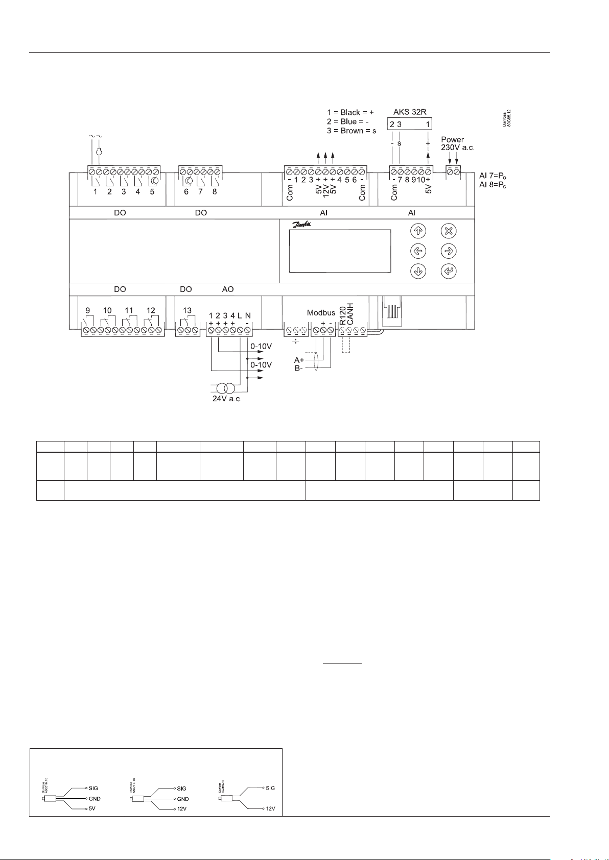
Connection, lower level
Warning
The supply voltage of AI may not share the
signal with other controllers.
DO DO1 DO2 DO3 DO4 DO5 DO6 DO7 DO8 DO9 DO10 DO11 DO12 DO13 DO14 DO15 Σ 1-15
I Max. 6 A
U All 24 V or
DO - Digital outputs, 15 pcs. DO1 - DO15
DO5 and DO6 are solid state relays.
6 A
6 A
6 A
(4)
(4)
(4)
(4)
0.5 A
min. 50 mA
Io < 1,5 mA
all 230 V a.c.
0.5 A
min. 50 mA
Io < 1,5 mA
6 A
(4)
6 A
(4)
6 A
(4)
6 A
(4)
6 A
(4)
All 24 V or
all 230 V a.c.
6 A
(4)
6 A
(4)
7 A
(3,5)
All 24 V or
all 230 V a.c.
7 A
(3,5)
92 A
Supply Voltage
230 V a.c.
The relays are de-rated to the specied values.
AO - Analogue output, 4 pcs. AO1 - AO4
Must be used when using a frequency converter or EC motors.
AI - Analogue inputs, 6 pcs. AI1 - AI6
Temperature sensor
• Pt 1000 ohm, AKS 11 or AKS 21.
• NTC 86K ohm @ 25°C, from digital scroll.
Pressure transmitters
Connect 24 V on N and L. Avoid earth fault current. Use
double-insulated transformer. The secondary side must
not be earthed.
Obtain 0-10 volts from terminals N and AO1, respectively N
and AO2. PAY ATTENTION TO THE POLARITY of N.
• Current: 0-20 mA / 4-20 mA, AKS 33 (supply = 12 V)
Modbus
AI - Analogue inputs, 4 pcs. AI7 - AI10
Pressure transmitters
• Ratiometric: 10-90% of supply, AKS 32R
It is important that the installation of the data communication
cable be done correctly. Cf. separate literature No. RC8AC.
Remember termination at the bus termination.
• Signal: 1-5 V, AKS 32
Factory settings: AI7=Po, AI8=Pc
Temperature sensor
See above
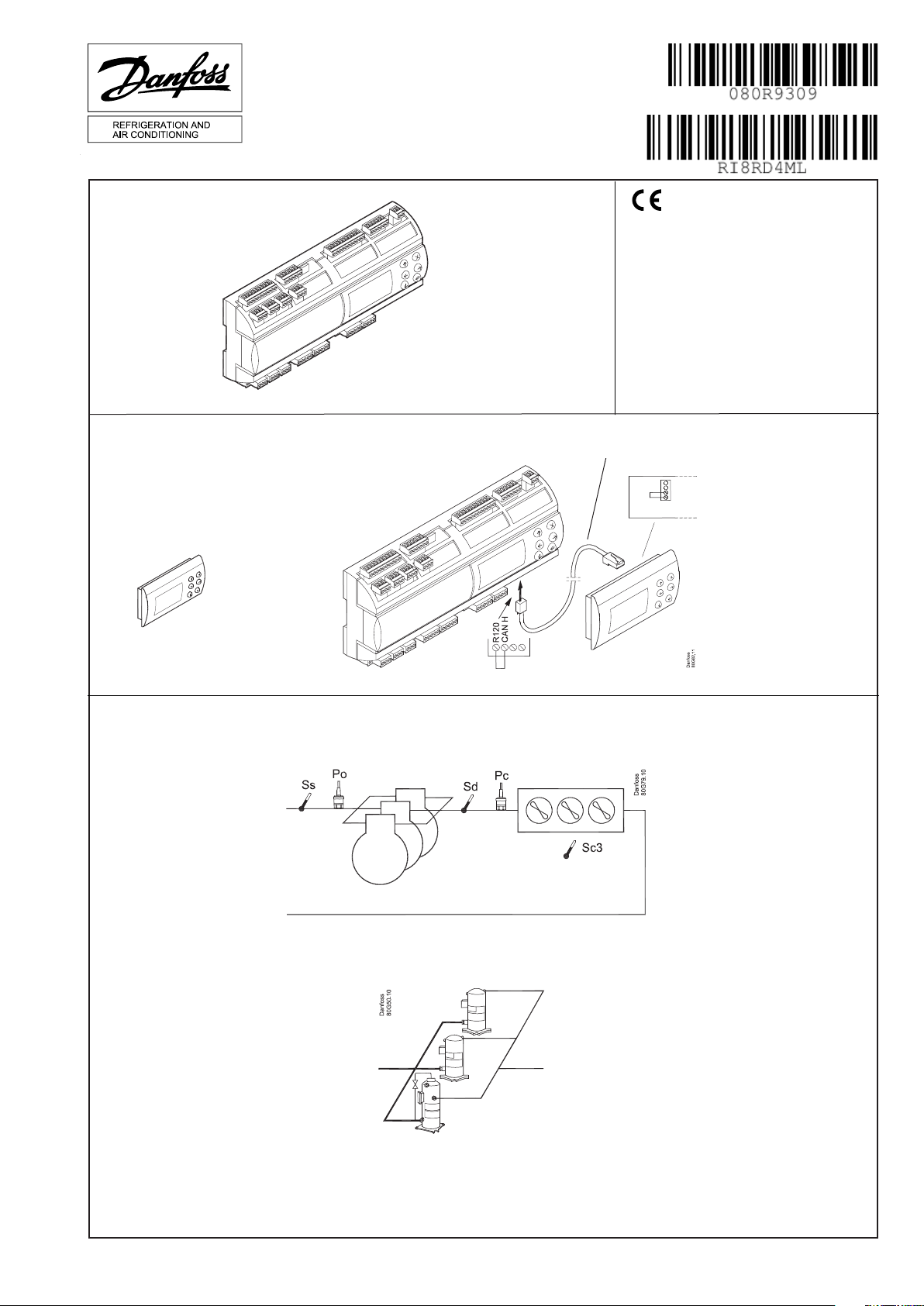
Termination
(Only if a remote display i connected)
Insert a jumper between the two connections on the left
(R120-CANH).
AKS 32R
AKS 32
AKS 33
2 Instructions RI8RD4ML © Danfoss 2015-04 AK-PC 651
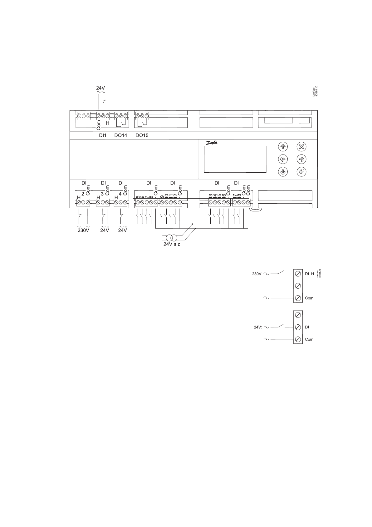
Connection, upper level
DI - High or low voltage Digital Inputs, 4 pcs. DI1 - DI4
Terminals = DI1H, DI1, DI common ...
230 V signal: Connect to DI_H
24 V signal: Connect to DI_
The connection may be a shut-down or interruption function.
Select what is to be activated during conguration.
DI - Low voltage Digital Inputs, 14 pcs. DI5 - DI18
All 24 V signal.
AK-PC 651 Instructions RI8RD4ML © Danfoss 2015-04 3

Dimensions
The capacity from the digital scroll compressor
Only DO5 or DO6
The capacity is divided into period times as "PWM period times". 100% capacity is delivered when cooling takes place for the whole
period.
An o time is required by the capacity control valve within the period and an on time is also permitted. There is "no cooling" when the
valve is on.
The controller itself calculates the capacity needed and will then vary it according to the cut-in time of the capacity control valve.
A limit is introduced if low capacity is needed so that the cooling does not go below 10%. This is because the compressor can cool
itself. This value can be increased if necessary.
Refrigeration
No refrigeration
Period time
Min. capacity
Copeland Stream 4
The signal can also be used to control one stream compressor with one unloading valve.
The compressor capacity is distributed by up to 50% for one relay (start) and the remaining 50-100% for the unloader. The unloader
is connected to DO5 or DO6.
Copeland Stream 6
The signal can also be used to control one stream compressor with two unloading valve.
The compressor capacity is distributed by up to 33% for one relay (start) and the remaining 33-100% for the two unloaders. The unloaders is connected to DO5 and DO6.
Bitzer CRII 4
The pulse signal can also be used to control one of the CRII with 2 unloaders (4 cylinders version).
Compressor capacity can be controlled from 10 to 100% depending on the pulsation of the unloaders. The compressor start signal is
connected to a relay output, and the unloaders are connected to DO5 and DO6.
Bitzer CRII 6
The pulse signal can also be used to control one of the CRII with 3 unloaders (6 cylinders version).
The compressor signal is connected to one relay output.
The two unloaders are connected to DO5 and DO6. The third is connected to a relay output.
The compressor capacity can be controlled from 10 to 67%, depending on the pulse of the unloaders.
The relay is then connected to the third unloader. When this relay is on, the capacity will be controlled between 33 and 100%.
4 Instructions RI8RD4ML © Danfoss 2015-04 AK-PC 651

Português
Conexão, nível inferior
Advertência
A tensão de alimentação do AI pode não compartilhar o sinal
com outros controladores.
DO DO1 DO2 DO3 DO4 DO5 DO6 DO7 DO8 DO9 DO10 DO11 DO12 DO13 DO14 DO15 Σ 1-15
I Max. 6 A
U Tudo 24 V ou
DO - Saídas digitais, 15 pcs. DO1 - DO15
DO5 e DO6 são relés de estado sólido.
6 A
6 A
6 A
(4)
(4)
(4)
(4)
0.5 A
min. 50 mA
Io < 1,5 mA
tudo 230 V CA
0.5 A
min. 50 mA
Io < 1,5 mA
6 A
(4)
6 A
(4)
6 A
(4)
6 A
(4)
Tudo 230 V CA
6 A
(4)
Tudo 24 V ou
6 A
(4)
6 A
(4)
7 A
7 A
(3,5)
(3,5)
Tudo 24 V ou
Tudo 230 V CA
92 A
Tensão de alimentação
230 V C.A.
Os relés são derated aos valores especicados.
AO - Saída analógica, 4 pcs. AO1 - AO4
AI - entradas analógicas, 6 pcs. AI1 - AI6
Sensor de temperatura
• Pt 1000 ohm, AKS 11 ou AKS 21.
• NTC 86K ohm @ 25°C, a partir de digital scroll.
Transmissores de pressão
• fonte de alimentação: 0-20 mA / 4-20 mA, AKS 33 (fornecimento = 12 V)
AI - entradas analógicas, 4 pcs. AI7 - AI10
Transmissores de pressão
• Ratiometric: 10-90% do fornecimento, AKS 32R
• Sinal: 1-5 V, AKS 32
Congurações de fábrica
Deverão ser utilizadas ao usar um conversor de frequência ou
motores EC.
24 V conectado no N e L. Evite corrente de falha do terra. Use
um transformador com isolamento duplo. O lado secundário
não deve ser aterrado.
Obtenha 0-10 volts dos terminais N e AO1, respectivamente N
e AO2. PRESTE ATENÇÃO À POLARIDADE de N.
Modbus
É importante que a instalação do cabo de comunicação de dados seja efetuada corretamente. Consulte a literatura separada
nº RC8AC.
Lembre-se: terminação na terminação do barramento.
AI7=Po, AI8=Pc,
Sensor de temperatura
Como acima
Terminação
(Somente se um display remoto estiver conectado)
Insira um jumper entre as duas conexões à esquerda
AKS 32R
AKS 32
AKS 33
(R120-CANH)
AK-PC 651 Instructions RI8RD4ML © Danfoss 2015-04 5

Conexão, nível superior
DI - Entradas digitais de alta ou baixa tensão, 4 pçs. DI1 - DI4
Terminais = DI1H, DI1, DI comum...
Sinal de 230 V: Conectar a DI_H
Sinal de 24 V: Conectar a DI_
A conexão pode ser um desligamento ou uma função
de interrupção. Selecione o que deve ser ativado durante
a conguração.
DI - Entradas digitais de baixa tensão, 14 pçs. DI5 - DI18
Todo o sinal de 24 V.
6 Instructions RI8RD4ML © Danfoss 2015-04 AK-PC 651

Dimensões
A capacidade do compressor de rolagem digital
Somente para DO5 ou DO6
A capacidade é dividida em períodos de tempo como “PWM period times”. É fornecida 100% da capacidade quando o resfriamento
acontece durante todo o período.
Um tempo desligado é necessário para a válvula de controle de capacidade, dentro do período e um tempo ligado também é permitido. Não há “resfriamento” quando a válvula estiver ligada.
O controlador por si próprio calcula a capacidade necessária e então irá variá-la de acordo com o tempo de ligar da válvula de controle
de capacidade.
Um limite é introduzido se uma baixa capacidade for necessária de modo que o resfriamento não caia para baixo de 10%. Isto é porque o compressor pode resfriar-se a si próprio. Esse valor poderá ser aumentado, se necessário.
Refrigeração
Não há refrigeração
Period time
Min. Capacidad
Copeland compressor de uxo (Stream 4)
O sinal de pulso também pode ser usado para controlar um compressor de uxo com uma válvula de descarregador.
A capacidade do compressor é distribuída por até 50% para um relé (início ) e os restantes 50-100% para o descarregador. O descarregador está conectado em DO5 ou DO6.
Copeland compressor de uxo (Stream 6)
O sinal de pulso também pode ser usado para controlar um compressor de uxo com dois válvulas de descarregador.
A capacidade do compressor é distribuída por até 33% para um relé (início ) e os restantes 33-100% para dois descarregadors. O descarregadors está conectado em DO5 e DO6.
Bitzer CRII 4
O sinal de pulso também pode ser utilizado para controlar um dos CRII com 2 descarregadores (versão com 4 cilindros).
A capacidade do compressor pode ser controlada de 10 a 100%, dependendo da pulsação dos descarregadores. O sinal de partida do
compressor está ligado a uma saída de relé, e os descarregadores estão conectados a DO5 e DO6.
Bitzer CRII 6
O sinal de pulso também pode ser utilizado para controlar um dos CRII com 3 descarregadores (versão com 6 cilindros).
O sinal do compressor está ligado a uma saída de relé.
Os dois descarregadores são conectados a DO5 e DO6. O terceiro está ligado a uma saída de relé.
A capacidade do compressor pode ser controlada de 10 a 67%, dependendo da pulsação dos descarregadores.
O relé é, então, ligado ao terceiro descarregador. Quando este relé for ligado, a capacidade será controlada entre 33 e 100%.
The Product contains electrical components
AK-PC 651 Instructions RI8RD4ML © Danfoss 2015-04 7
And may not be disposed together with domestic waste.
Equipment must be separate collected with Electrical and Electronic waste. According to Local and currently valid legislation.
ADAP-KOOL®
 Loading...