

Installation Guide
Danfoss
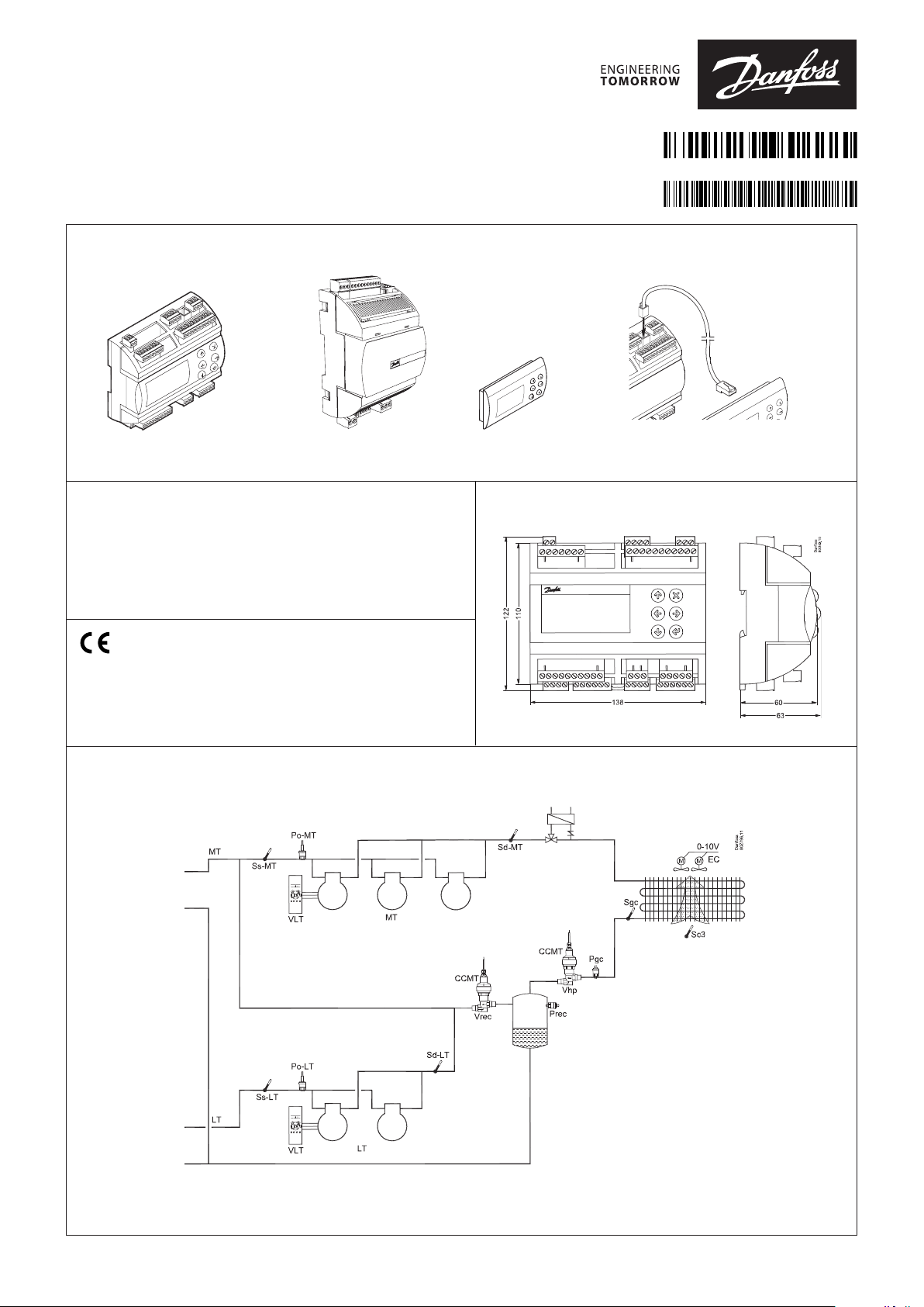
AK-PC 572
Identification | Identificação | Identificatie | Identification | Identificación
80G393
080R9330
AN29572719924701- 000201
1.5 m: 080G0075
3.0 m: 080G0076
AK-PC 572 EKE 1P
Power supply | Fonte de energia | Stroomvoorziening
Source de courant | Fuente de alimentación
AK-PC 572 24 V AC / DC 17 VA
EKE 1P 24 V AC / DC 7 – 20 VA
IP 20
-20 – 60 °C
(0 – 140 °F)
RH max. 90% non condensing
Principle | Princípio | Beginsel | Principe | Principio
MMIGRS2
Dimension | Dimensão | Dimensie | Dimension | Dimensión
© Danfoss | DCS (vt) | 2019.12
AN29572719924701-000201 | 1
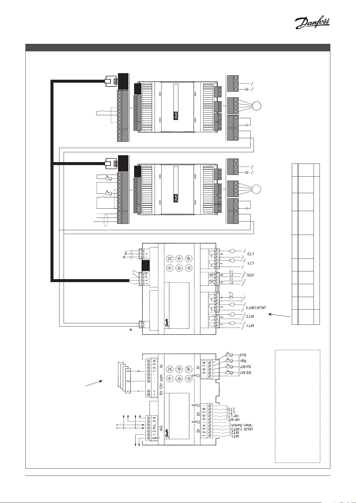
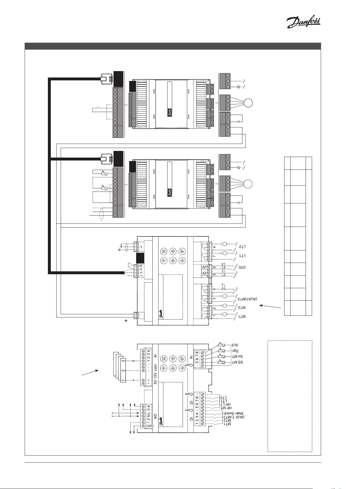
Connections
DO
HR / DO
s
80G386
ENGLISH
Danfos
CAN RJ
COM
CAN RJ
AI1
COM
AI1
AI2
AI2
AI3
AI3
AI4
AI4
COM
COM
CAN RJ
DI1
DI2
5V+
COM
RGND
D+
D –
COM
AI1
AI2
AI3
AI4
COM
DI1
DI2
5V+
COM
RGND
D+
D –
CAN RJ
DI1
DI2
5V+
COM
RGND
D+
D –
COM
AI1
AI2
AI3
AI4
COM
DI1
DI2
5V+
COM
RGND
D+
D –
EKE 1P
EKE 1P
HR / DI Aux 3
LT - SS
LT - Sd
Oil / DI Aux 2
MODBUS Field Bus
A+
B-
NC1
C1
NC1
NO1
C1
NO1
B2
B2
B1
B1
A2
A2
A1
A1
Bat+
Bat+
GND
+/~
GND
–/~
+/~
+
–/~
-
NC1
C1
NC1
NO1
C1
NO1
B2
B2
B1
B1
A2
A2
A1
A1
Bat+
Bat+
GND
+/~
GND
–/~
+/~
+
–/~
-
AUX 3
M
Vrec
Battery back-up
24 V
Power
Important!
Wait before connecting the power supply to the
modules!
In order to set the addresses 96 and 97, you must fol-
low the recommended procedure. See page 4.
AUX 2
32 A
M
Vhp
6 A
(4)
Battery back-up
24 V
6 A
(4)
Power
0.5 A
min. 50 mA
Ioff < 1.5 mA
Connection, lower level Connection, upper level
24 V AC/DC
Warning
The supply voltage
of AI may not share
the signal with
other controllers.
Separate
supply
1 = Black = +
2 = Blue = -
AKS 32R
AKS 2050
Extern
24 V
MODBUS
3 = Brown = s
MBS 8250
VSD MT
AC/DC
AI 1 = PoMT
AI 2 = PoLT
AI 3 = Pgc
AI 4 = Prec
0 – 10 V
VSD LT
0 – 10 V
CAN RJ
LN
CANBUS D- D+
DO
DO DO1 DO2 DO3 DO4 DO5 DO6 DO7 DO8 Σ 1-8
0.5 A
min. 50 mA
6 A
(4)
6 A
(4)
10 A
(3.5)
(3.5)
I Max. 10 A
Ioff < 1,5 mA
U All 24 V or all 230 V AC
2 | AN29572719924701-000201
Electric noise
Signal cables for sensors, DI inputs, data communication
and display must be kept separate from high voltage
(230 V) electric cables:
- Use separate cable trays
- Keep a distance between high voltage and signal cables
of at least 10 cm
Fan
0 – 10 V
- Cables longer than 3 m at the DI input should be avoided
© Danfoss | DCS (vt) | 2019.12
MAIN MODULE
AO - Analogue output, 3 pcs. AO1, AO3, AO4
Must be used if using frequency converters or EC motors.
Connect 24 V on N and L (separate power supply) Avoid earth fault
current.
- Use double-insulated transformer. The secondary side must not
be earthed.
Obtain 0-10 volts from terminals Com-AO1, N-AO3 and N-AO4.
PAY ATTENTION TO THE POLARITY of N.
(AO3 and AO4 are galvanically isolated. AO1 is not).
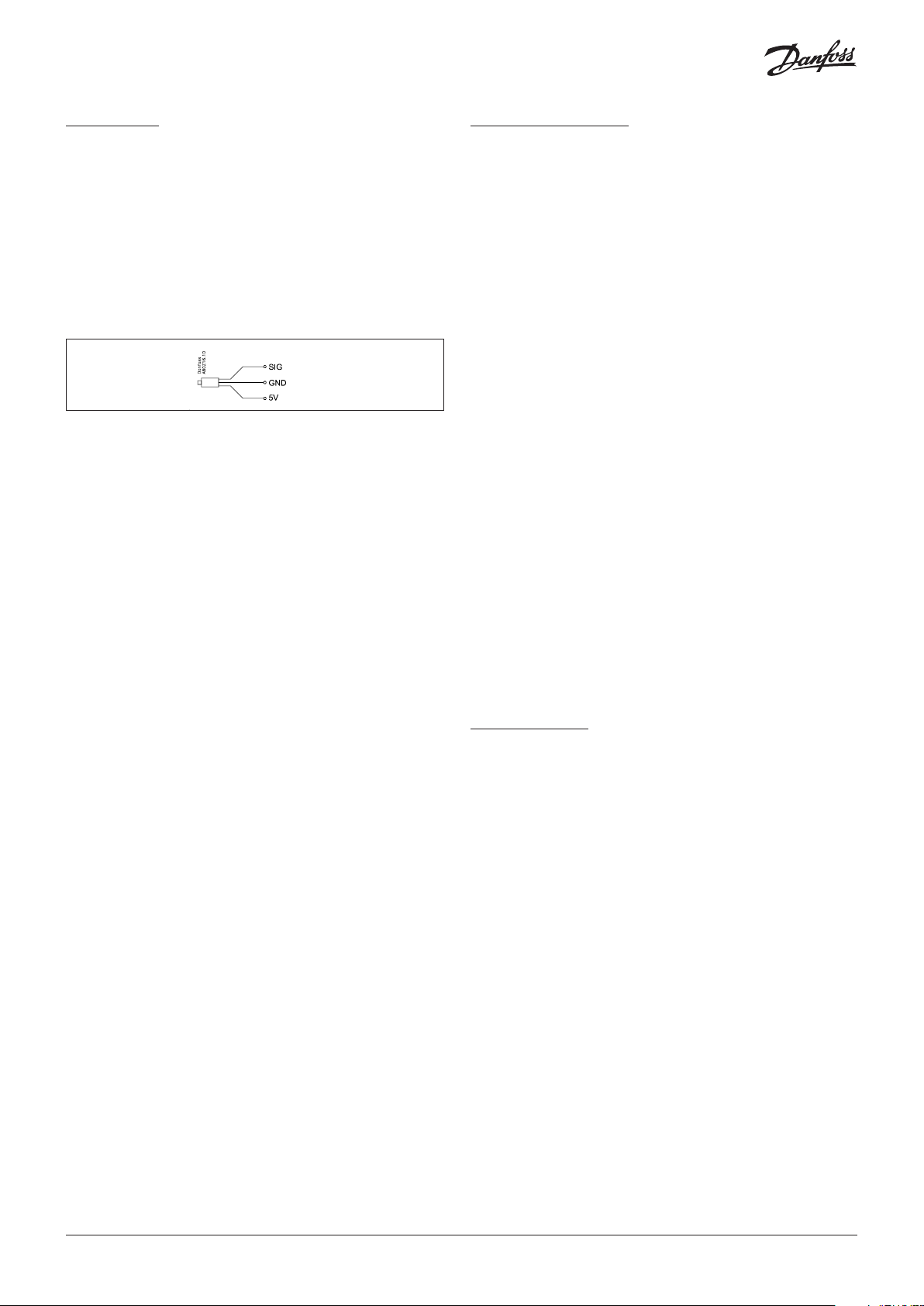
AI - Analogue inputs
Pressure transmitters, 4 pcs. AI1 - AI4
AKS 32R /
AKS 2050 /
MBS 8250
10 – 90% ratiometric
HIGH PRESSURE MODULE
Supply voltage to high pressure module
The power supply can be taken from the main module.
Battery
Ensure that the valve closes if there is no supply voltage.
Stepper valve
FX ventil type CCMT.
Connector:
A1 5: WHITE
A2 6: BLACK
B1 7: RED
B2 8: GREEN
CANBUS
Data communication to the main module.
Temperature sensors, 4 pcs. AI5 - AI8
• Pt 1000 ohm, AKS 11 or AKS 21.
DI - Digital switch inputs, 8 pcs. DI1 - DI8
The connection may be a shut-down or interruption function.
Select what is to be activated during configuration.
(DI3 can be used as an AUX1 input, but only if regulated with 2 MT
compressors).
Supply
24 V AC or DC Class II is required.
AK-PC 572 17 VA
EKE 1P 20 VA
CANBUS
Communication to the high pressure module and to the receiver
module
"L" to "L" and "H" to "H"
A jumper must be connected between "H" and "R".
Terminate on the AK-PC with a resistance of 120 ohm.
If mounting an external display, the termination must also be done
at the display. See next page.
Important!
In order to establish communication with the extension modules, you
must follow the recommended procedure. See next page.
MODBUS
It is important that the installation of the data communication
cable is carried out correctly. See separate literature no. RC8AC...
Remember termination at the termination points.
DO - Digital outputs, 8 pcs. DO1-DO8
DO5 and DO6 are solid state relays. The outputs are used for
connecting a Bitzer CRII. If a Bitzer CRII is not being connected,
output DO6 can be used for activation of an oil valve.
The relays are de-rated to the specified values.
The alarm relay will be driven under normal operation and
will drop in the event of alarms and insufficient voltage to the
controller.
(DO3 can be used as an AUX1 output, but only if regulated with 2
MT compressors).
Sensor inputs
• Pt 1000 ohm, AKS 11 or AKS 21.
Contact input AUX 2
Signal from oil level,
or input for fan alarm or another alarm.
Relay output AUX 2
Activation of de-superheating or hot gas dump.
MODBUS
Data communication with other devices.
It is important that the installation of the data communication
cable is performed correctly.
See separate literature no. RC8AC...
Remember termination at the termination points. Use a twisted
pair shielded cable, but do not connect the shield to the EKE 1P.
RECEIVER MODULE
Supply voltage to high pressure module
The power supply can be taken from the main module.
Battery
Ensure that the valve closes if there is no supply voltage.
Stepper valve
FX valve type CCMT.
Connector:
A1 5: WHITE
A2 6: BLACK
B1 7: RED
B2 8: GREEN
CANBUS
Data communication to the main module.
The section must be terminated using a 120 ohm resistor.
Contact input AUX 3
Signal from heat recovery,
or input for fan alarm or another alarm.
Relay output AUX 3
Activation of heat recovery,
or AUX 3 output for de-superheating or hot gas dump.
© Danfoss | DCS (vt) | 2019.12
AN29572719924701-000201 | 3
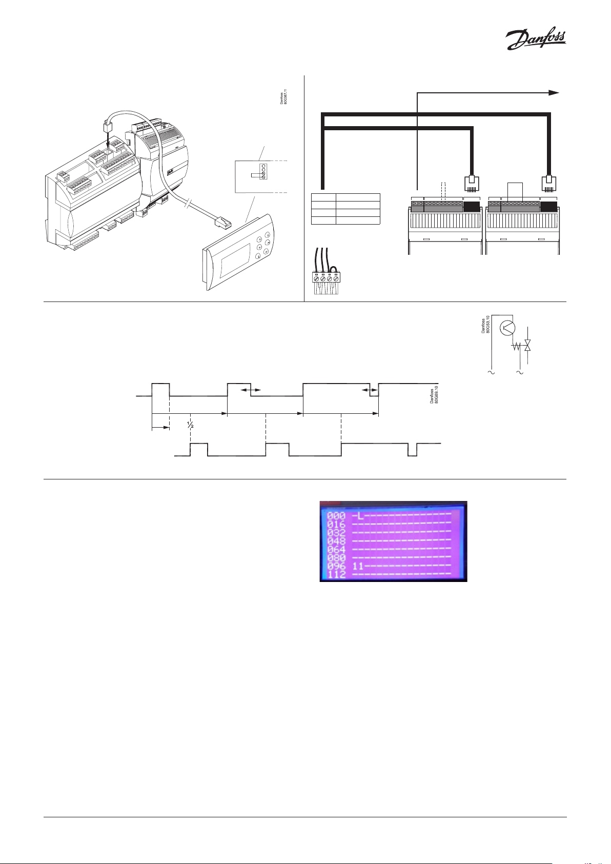
External display
80G3867
R = 1200Ω
L→H
Extension modules
MODBUS master
H - R
R120 Bridge - CAN H
CAN H Red
CAN L Green
C GND Yellow
Yellow
Green
Red
D –
D+
RGND
High pressure Receiver
Bitzer CRII
The pulse signal can also be used to control one of the CRII with 2 unloaders (4 cylinders' version).
Compressor capacity can be controlled from 10 to 100% depending on the pulsation of the unloaders.
The unloaders are connected to DO5 and DO6.
Connect compressor relay to DO-MT1.
0 V / Open 5 V
ANALOGUE / DIGITAL INPUTRS-485 RS-485 CAN-RJCAN-RJ ANALOGUE / DIGITAL INPUT
COM
5V+
DI2
CAN RJ
DI1
COM
AI4
AI3
AI2
AI1
COM
COM
5V+
DI2
DI1
COM
AI4
D –
D+
AI3
RGND
Danfoss
CAN RJ
AI2
AI1
COM
Unloader 2 follows unloader 1
but is offset a ½ period.
Important
Read the following before you connect the controller and the two
valve modules to the supply voltage.
The EKE 1P is pre-configured to determine the extension module
mode based on the AI4 status of the EKE 1P:
AI4 Open circuit: high pressure module
AI4 short circuit to 5V: receiver module
Alternatively the EKE 1P configuration may be set by connecting
a graphical display to the EKE 1P. See separate EKE 1P documentation.
If you wish to check the addresses of the two valve modules, you
should carry out the following:
1. Connect all modules to the power supply.
2. Immediately press on both the "X" and "Enter" buttons while the
controller is starting up.
3. Find the display "CAN SETTINGS" > "ACTIVE NODES"
Unloader 1
Unloader 2
The two 1-digits represent the addresses 96 (HP module) and 97
(Receiver module) respectively.
If you remove the connection to a valve module, the display of
the address will also disappear.
4 | AN29572719924701-000201
© Danfoss | DCS (vt) | 2019.12
Conexões
DO
HR / DO
s
80G386
PORTUGUÊS
Danfos
CAN RJ
COM
CAN RJ
AI1
COM
AI1
AI2
AI2
AI3
AI3
AI4
AI4
COM
COM
CAN RJ
DI1
DI2
5V+
COM
RGND
D+
D –
COM
AI1
AI2
AI3
AI4
COM
DI1
DI2
5V+
COM
RGND
D+
D –
CAN RJ
DI1
DI2
5V+
COM
RGND
D+
D –
COM
AI1
AI2
AI3
AI4
COM
DI1
DI2
5V+
COM
RGND
D+
D –
EKE 1P
EKE 1P
HR / DI Aux 3
LT - SS
LT - Sd
Oil / DI Aux 2
MODBUS Field Bus
A+
B-
NC1
C1
NC1
NO1
C1
NO1
B2
B2
B1
B1
A2
A2
A1
A1
Bat+
Bat+
GND
+/~
GND
–/~
+/~
+
–/~
-
NC1
C1
NC1
NO1
C1
NO1
B2
B2
B1
B1
A2
A2
A1
A1
Bat+
Bat+
GND
+/~
GND
–/~
+/~
+
–/~
-
AUX 3
M
Vrec
Suporte da bateria
24 V
Consumo
Importante!
Espere antes de conectar a fonte de alimentação aos
módulos!
Para definir os endereços 96 e 97, é preciso seguir o
procedimento recomendado. Consulte a página 7.
AUX 2
M
Vhp
24 V
32 A
6 A
(4)
Suporte da bateria
6 A
(4)
Consumo
0.5 A
min. 50 mA
Ioff < 1,5 mA
Conexão, nível inferior Conexão, nível superior
0.5 A
min. 50 mA
Ioff < 1,5 mA
MODBUS
6 A
6 A
10 A
(4)
(4)
(3,5)
CAN RJ
CANBUS D- D+
(3,5)
DO DO1 DO2 DO3 DO4 DO5 DO6 DO7 DO8 Σ 1-8
I Max. 10 A
CA/CC de 24 V
LN
U Tudo 24 V ou tudo 230 V CA
DO
AI 1 = PoMT
AI 2 = PoLT
AI 3 = Pgc
VSD MT
0 – 10 V
AI 4 = Prec
VSD LT
0 – 10 V
Aviso
A tensão de alimentação
do AI pode não partilhar
1 = Preto = +
2 = Azul = -
3 = Castanho = s
AKS 32R
AKS 2050
MBS 8250
o sinal com outros
controladores.
© Danfoss | DCS (vt) | 2019.12
Alimentação
em separado
CA/CC de 24 V
externo
Ventoinha
0 – 10 V
Ruído elétrico
Cabos de sinal para sensores, entradas DI, comunicação de
dados e display devem ser mantidos separados de outros
alta tensão (230 V) cabos elétricos:
- Use condutores de cabos separados
- Manter uma distância entre os cabos de alta tensão e de
sinal de pelo menos 10 cm
- Cabos de extensão superior a 3 m na entrada DI devem
ser evitados
AN29572719924701-000201 | 5

MÓDULO PRINCIPAL
AO - Saída analógica, 3 pçs. AO1, AO3, AO4
Deve ser usada ao usar conversores de frequência ou motores EC.
Conecte 24 V em N e L (fonte de alimentação separada) Evite a corrente de falha de aterramento.
- Use um transformador com isolamento duplo. O lado secundário
não deve ser aterrado.
Obtenha 0-10 volts dos terminais Com-AO1, N-AO3 eN-AO4.
PRESTE ATENÇÃO À POLARIDADE de N.
(AO3 e AO4 são isolados galvanicamente. AO1 não é).
AI - Entradas analógicas
Transmissores de pressão, 4 pçs. AI1 - AI4
AKS 32R /
AKS 2050 /
MBS 8250
10 – 90% ratiometric
MÓDULO DE ALTA PRESSÃO
Tensão de alimentação para o módulo de alta pressão
A fonte de alimentação pode ser tirada do módulo principal.
Bateria
Certifique-se de que a válvula feche se não houver tensão de
alimentação.
Válvula de passo
Válvula FX tipo CCMT.
Conector:
A1 5: BRANCO
A2 6: PRETO
B1 7: Vermelho
B2 8: VERDE
CANBUS
Comunicação de dados ao módulo principal.
Sensores de temperatura, 4 pçs. AI5 - AI8
• Pt 1000 ohm, AKS 11 ou AKS 21.
DI - Entradas de interruptores digitais, 8 pçs. DI1 - DI8
A conexão pode ser um desligamento ou função de interrupção.
Selecione o que deverá ser ativado durante a configuração.
(DI3 pode ser usada como entrada AUX1, mas apenas se regulada
com 2 compressores MT).
Fonte de energia
24 V c.a. ou c.c. Classe II obrigatória.
AK-PC 572 17 VA
EKE 1P 20 VA
CANBUS
Comunicação com o módulo de alta pressão e com o módulo
receptor
"L" a "L" e "H" a "H"
É necessário conectar um jumper entre "H" e "R".
Finalize no AK-PC com uma resistência de 120 ohm.
Se montar um monitor externo, a finalização também deve ser
efetuada no monitor. Veja a página seguinte.
Importante!
Para estabelecer comunicação com os módulos de extensão, deve
seguir o procedimento recomendado. Veja a página seguinte.
MODBUS
É importante que a instalação do cabo de comunicação de dados
seja realizada corretamente. Consulte a literatura separada n°
RC8AC...
Lembre-se: terminação nos pontos de terminação.
DO - Saídas digitais, 8 pçs. DO1-DO8
DO5 e DO6 são relés de estado sólido. As saídas são usadas para
conectar um Bitzer CRII. Se não for conectado um Bitzer CRII, a
saída DO6 pode ser usada para ativação de uma válvula de óleo.
Os relés são reduzidos aos valores especificados.
O relé de alarmes será acionado durante a operação normal e
desarmará em caso de alarmes e de tensão insuficiente para o
controlador.
(DO3 pode ser usada como saída AUX1, mas apenas se regulada
com 2 compressores MT).
Entradas de Sensores
• Pt 1000 ohm, AKS 11 ou AKS 21.
Entrada de contato AUX2
Sinal do nível de óleo,
ou entrada para o alarme de ventilador ou outro alarme.
Saída do relé AUX 2
Ativação do dessuperaquecimento ou despejo de gás quente.
MODBUS
Comunicação de dados com outros dispositivos.
É importante que a instalação do cabo de comunicação de dados
seja efetuada corretamente.
Consulte o documento em separado n.º RC8AC...
Não se esqueça da finalização em ambos os pontos de finalização.
Utilize um cabo blindado de fios entrelaçados, mas não ligue a
blindagem ao EKE 1P.
MÓDULO RECEPTOR
Tensão de alimentação para o módulo de alta pressão
A fonte de alimentação pode ser tirada do módulo principal.
Bateria
Certifique-se de que a válvula feche se não houver tensão de
alimentação.
Válvula de passo
Válvula FX tipo CCMT.
Conector:
A1 5: BRANCO
A2 6: PRETO
B1 7: Vermelho
B2 8: VERDE
CANBUS
Comunicação de dados ao módulo principal.
A seção precisa ser terminada com o uso de um resistor de 120 ohms.
Entrada de contato AUX 3
Sinal da recuperação de calor,
ou entrada para o alarme de ventilador ou outro alarme.
6 | AN29572719924701-000201
Saída do relé AUX 3
Ativação da recuperação de calor,
ou saída AUX 3 para dessuperaquecimento ou despejo de gás
quente.
© Danfoss | DCS (vt) | 2019.12

Display externo
80G3867
R = 1200Ω
L→H
Módulos de extensão
Master MODBUS
H - R
0 V / Abrir 5 V
ENTRADA ANALÓGICA / DIGITAL ENTRADA ANALÓGICA / DIGITAL
R120 Ponte - CAN H
CAN H Vermelho
CAN L Verde
C GND Amarelo
Amarelo
Verde
Vermelho
RS-485 RS-485 CAN-RJCAN-RJ
COM
5V+
D –
D+
RGND
Alta pressão Recetor
Bitzer CRII
O sinal de pulso também pode ser utilizado para controlar um dos CRII com 2 descarregadores (versão
com 4 cilindros).
A capacidade do compressor pode ser controlada de 10 a 100%, dependendo da pulsação dos descarregadores. O descarregador está ligado a DO5 ou DO6.
Conecte o relé do compressor a MT1.
Danfoss
DI2
CAN RJ
DI1
COM
AI4
AI3
AI2
AI1
COM
COM
5V+
DI2
D –
D+
RGND
CAN RJ
DI1
COM
AI4
AI3
AI2
AI1
COM
O descarregador 2 segue o
descarregador 1, mas tem ½
período de deslocamento.
Importante
Leia o que se segue antes de conectar o controlador e os dois
módulos de válvula à tensão de alimentação.
Caso queira verificar os endereços dos dois módulos de válvula,
faça o seguinte:
1. conecte todos os módulos à fonte de alimentação
2. Pressione imediatamente os botões "X" e "Enter" enquanto o
controlador estiver iniciando.
3. Encontre a visualização "CAN SETTINGS" > "ACTIVE NODES"
Descarregador 1
Descarregador 2
Os dois dígitos 1 representam os endereços 96 (módulo HP) e 97
(módulo recetor) respetivamente.
Se a conexão com um módulo de válvula for removida, a
visualização do endereço também desaparecerá.
© Danfoss | DCS (vt) | 2019.12
AN29572719924701-000201 | 7

Anschluss
HR / DO
s
80G386
DEUTSCH
Danfos
CAN RJ
COM
CAN RJ
AI1
COM
AI1
AI2
AI2
AI3
AI3
AI4
AI4
COM
COM
CAN RJ
DI1
DI2
5V+
COM
RGND
D+
D –
COM
AI1
AI2
AI3
AI4
COM
DI1
DI2
5V+
COM
RGND
D+
D –
CAN RJ
DI1
DI2
5V+
COM
RGND
D+
D –
COM
AI1
AI2
AI3
AI4
COM
DI1
DI2
5V+
COM
RGND
D+
D –
EKE 1P
EKE 1P
HR / DI Aux 3
LT - SS
LT - Sd
Oil / DI Aux 2
MODBUS Field Bus
A+
B-
NC1
C1
NC1
NO1
C1
NO1
B2
B2
B1
B1
A2
A2
A1
A1
Bat+
Bat+
GND
+/~
GND
–/~
+/~
+
–/~
-
NC1
C1
NC1
NO1
C1
NO1
B2
B2
B1
B1
A2
A2
A1
A1
Bat+
Bat+
GND
+/~
GND
–/~
+/~
+
–/~
-
AUX 3
M
Vrec
Back-up batterij
24 V
Vermogen
Wichtig!
Warten Sie, bevor Sie die Spannungsversorgung an
die Module anschließen!
Sie müssen wie folgt vorgehen, um die Adressen 96
und 97 zu festzulegen. Siehe Seite 11.
DO AUX 2
M
Vhp
Back-up batterij
24 V
32 A
6 A
6 A
(4)
(4)
Vermogen
0,5 A
min. 50 mA
Ioff < 1,5 mA
Verbindung, untere Ebene Verbindung, obere Ebene
24 V AC/DC
Waarschuwing
De voedingsspanning
van AI mag het signaal
niet met andere
regelaars delen.
1 = Zwart = +
2 = Blauw = -
3 = Bruin = s
AKS 32R
AKS 2050
MBS 8250
MODBUS
AI 1 = PoMT
VSD MT
0 – 10 V
AI 2 = PoLT
AI 3 = Pgc
AI 4 = Prec
VSD LT
0 – 10 V
CAN RJ
LN
CANBUS D- D+
DO
DO DO1 DO2 DO3 DO4 DO5 DO6 DO7 DO8 Σ 1-8
0,5 A
min. 50 mA
6 A
(4)
6 A
(4)
10 A
(3,5)
(3,5)
I Max. 10 A
Ioff < 1,5 mA
U Alle 24 V oder alle 230 V AC
Aparte
8 | AN29572719924701-000201
voeding
Externe 24 V
AC/DC
Funkenstörung
Signalkabeln für Fühlern, DI-Eingängen, Datenkommunika-
tion und Display sind getrennt von Hoch Spannungs (230
V) Elektrokabeln zu verlegen:
- Separate Kabeltröge verwenden.
- Zwischen den Hochspannungs- und Signal-Kabeln einen
Abstand von mindestens 10 cm halten.
Ventilator
0 – 10 V
- Bei DI-Eingängen Kabel länger als 3 m vermeiden.
© Danfoss | DCS (vt) | 2019.12

HAUPTMODUL
AO -analoger Ausgang, 3 Stück AO1, AO3, AO4
Müssen verwendet werden, wenn Frequenzumrichter oder ECMotoren eingesetzt werden.
Schließen Sie 24 V an N und L (separate Versorgungsspannung)
an. Vermeiden Sie einen Erdschlussstrom.
- Verwenden Sie doppelt isolierte Transformatoren. Die sekundäre
Seite darf nicht geerdet werden.
0-10 Volt erhalten Sie von den Klemmen Com-AO1, N-AO3 und
N-AO4.
ACHTEN SIE AUF DIE POLARITÄT von N.
(AO3 und AO4 sind galvanisch getrennt, AO1 nicht).
AI - analoge Eingänge
Druckmessumformer, 4 Stück AI1 – AI4
HOCHDRUCKMODUL
Versorgungsspannung zum Hochdruckmodul
Die Versorgungsspannung kann vom Hauptmodul genommen
werden.
Batterie
Achten Sie darauf, dass das Ventil schließt, sobald keine Spannung
anliegt.
Schrittmotorventil
FX Ventiltyp CCMT.
Anschluss:
A1 5: WEISS
A2 6: SCHWARZ
B1 7: Rot
B2 8: GRÜN
AKS 32R /
AKS 2050 /
MBS 8250
10 – 90% ratiometric
Temperaturfühler, 4 Stück AI5 – AI8
• Pt 1000 Ohm, AKS 11 oder AKS 21.
DI - digitale Schalteingänge, 8 Stück DI1 – DI8
Der Anschluss kann als Ausschalt- oder Unterbrechungsfunktion
erfolgen. Wählen Sie während der Konfiguration, was aktiviert
wird.
(DI3 kann als Eingang AUX1 verwendet werden, aber nur bei
Regelung mit 2 MT-Verdichtern).
Spannungsversorgung
24 V Wechsel- oder Gleichspannung Klasse II ist erforderlich.
AK-PC 572 17 VA
EKE 1P 20 VA
CANBUS
CKommunikation zum Hochdruckmodul und Empfängermodul
„L“ an „L“ und „H“an „H“
Zwischen „H“ und „R“ muss eine Brücke angeschlossen werden.
Sluit af op de AK-PC met een weerstand van 120 ohm.
Bij montage van een externe display moet de afsluiting ook bij de
display gebeuren. Zie de volgende pagina.
Belangrijk!
Om communicatie met de uitbreidingsmodules tot stand te
brengen moet u de aanbevolen procedure volgen. Zie de
volgende pagina.
MODBUS
Das Datenübertragungskabel ist unbedingt korrekt anzuschließen. Siehe separate dokumentation Nr. RC8AC...
Denken Sie an die Terminierung an den Terminierungspunkten.
DO - digitale Ausgänge, 8 Stück DO1-DO8
DO5 und DO6 sind Halbleiterrelais. Die Ausgänge werden für den
Anschluss eines Bitzer CRII verwendet. Wenn kein Bitzer CRII angeschlossen wird, kann der Ausgang DO6 für die Aktivierung eines
Ölventils verwendet werden.
Die Relais wurden auf vorgegebene Werte heruntergeregelt.
Das Alarmrelais wird im normalen Betrieb aktiviert und fällt bei
Alarmen und ungenügender Spannungsversorgung des Reglers ab.
(DO3 kann als Ausgang AUX1 verwendet werden, aber nur bei
Regelung mit 2 MT-Verdichtern).
CANBUS
Datenübertragung zum Hauptmodul.
Fühlereingänge
• Pt 1000 Ohm, AKS 11 oder AKS 21.
Kontakt Eingang AUX 2
Signal von Ölstand
oder Eingang für Lüfteralarm oder anderen Alarm.
Relaisausgang AUX 2
Aktivierung der Enthitzung oder Heißgasentladung.
MODBUS
Datacommunicatie met andere apparaten.
Het is belangrijk dat de datacommunicatiekabel correct is
aangesloten.
Zie de aparte documentatie met nummer RC8AC...
Vergeet de afsluiting bij de afsluitpunten niet.
Gebruik een afgeschermde kabel met getwiste aderparen, maar
verbind de afscherming niet met de EKE 1P.
EMPFÄNGERMODUL
Versorgungsspannung zum Hochdruckmodul
Die Versorgungsspannung kann vom Hauptmodul genommen
werden.
Batterie
Achten Sie darauf, dass das Ventil schließt, sobald keine Spannung
anliegt.
Schrittmotorventil
FX Ventiltyp CCMT.
Anschluss:
A1 5: WEISS
A2 6: SCHWARZ
B1 7: Rot
B2 8: GRÜN
CANBUS
Datenübertragung zum Hauptmodul.
Dieser Abschnitt muss mit einem 120-Ohm-Widerstand
abgeschlossen werden.
Kontakt Eingang AUX 3
Signal von Wärmerückgewinnung
oder Eingang für Lüfteralarm oder anderen Alarm.
Relaisausgang AUX 3
Aktivierung der Wärmerückgewinnung
oder Ausgang AUX 3 für Enthitzung oder Heißgasentladung.
© Danfoss | DCS (vt) | 2019.12
AN29572719924701-000201 | 9

Externes Display
80G3867
R = 1200Ω
L→H
Uitbreidingsmodules
MODBUS master
H - R
0 V / Open 5 V
ANALOOG / DIGITALE INGANG ANALOOG / DIGITALE INGANG
R120 Brug – CAN H
CAN H Rood
CAN L Groen
C GND Geel
Geel
Groen
Rood
RS-485 RS-485 CAN-RJCAN-RJ
COM
5V+
DI2
D –
D+
RGND
Hoge druk Vloeistofvat
Bitzer CRII
Das Puls-signal kann auch dazu verwendet werden, um einen CRII-Verdichter mit zwei Entlastungsventile
zu regeln. (4 Zylinder Version)
Die Verdichterleistung kann von 10 bis 100% regeln abhängig von der Pulsierung der Entlastungsventile.
Die Entlastungsventile sind mit einem DO5 oder einem DO6 verbunden.
Schließen Sie das Verdichterrelais an MT1 an.
Danfoss
CAN RJ
DI1
COM
AI4
AI3
AI2
AI1
COM
COM
5V+
DI2
D –
D+
RGND
CAN RJ
DI1
COM
AI4
AI3
AI2
AI1
COM
Entlasung 2 folgt Entlasung 1
aber wird mit einer ½ Periode
verschieben. Entlasung 2 folgt
Entlasung 1 aber wird mit einer
½ Periode verschieben.
Wichtig
Lesen Sie die nachfolgenden Informationen, bevor Sie den
Regler und die zwei Ventilmodule an die Spannungsversorgung
anschließen.
Um die Adressen der beiden Ventilmodule zu überprüfen, gehen
Sie wie folgt vor:
1. Schließen Sie alle Module an die Spannungsversorgung an..
2. Drücken Sie dann sofort die Tasten „X“ und „Enter“, während der
Regler hochfährt.
3. Öffnen Sie das Display „CAN SETTINGS“ > „ACTIVE NODES“ (CANEINSTELLUNGEN > AKTIVE KNOTEN)
Entlasung 1
Entlasung 2
De twee 1-cijfers staan respectievelijk voor de adressen 96 (HPmodule) en 97 (Vloeistofvatmodule).
Wenn Sie die Verbindung zu einem Ventilmodul trennen, wird
auch die Anzeige der Adresse ausgeblendet.
10 | AN29572719924701-000201
© Danfoss | DCS (vt) | 2019.12

Raccordements
HR / DO
s
80G386
FRANÇAIS
Danfos
CAN RJ
COM
CAN RJ
AI1
COM
AI1
AI2
AI2
AI3
AI3
AI4
AI4
COM
COM
CAN RJ
DI1
DI2
5V+
COM
COM
AI1
AI2
AI3
AI4
COM
DI1
DI2
5V+
COM
RGND
D+
D –
RGND
D+
D –
CAN RJ
DI1
DI2
5V+
COM
RGND
D+
D –
COM
AI1
AI2
AI3
AI4
COM
DI1
DI2
5V+
COM
RGND
D+
D –
EKE 1P
EKE 1P
HR / DI Aux 3
LT - SS
LT - Sd
Oil / DI Aux 2
MODBUS Field Bus
A+
B-
NC1
C1
NC1
NO1
C1
NO1
B2
B2
B1
B1
A2
A2
A1
A1
Bat+
Bat+
GND
+/~
GND
–/~
+/~
+
–/~
-
NC1
C1
NC1
NO1
C1
NO1
B2
B2
B1
B1
A2
A2
A1
A1
Bat+
Bat+
GND
+/~
GND
–/~
+/~
+
–/~
-
AUX 3
M
Vrec
Batterie de secours
24 V
Puissance
Important!
Patienter avant de brancher l'alimentation sur les
modules !
Pour régler les adresses 96 et 97, suivre la procédure
conseillée. Voir page 13.
DO AUX 2
32 A
M
Vhp
6 A
(4)
Batterie de secours
24 V
6 A
(4)
Puissance
0,5 A
min. 50 mA
Ioff < 1,5 mA
Connexion, niveau inférieurConnexion, niveau supérieur
24 V CA/CC
Avertissement
La tension d'alimentation
d'AI ne peut pas partager
0,5 A
min. 50 mA
6 A
6 A
10 A
(4)
(4)
(3,5)
Ioff < 1,5 mA
MODBUS
CAN RJ
CANBUS D- D+
(3,5)
DO DO1 DO2 DO3 DO4 DO5 DO6 DO7 DO8 Σ 1-8
I Max. 10 A
LN
U Tous 24 V ou tous 230 V c.a.
DO
AI 1 = PoMT
AI 2 = PoLT
AI 3 = Pgc
VSD MT
0 – 10 V
AI 4 = Prec
VSD LT
0 – 10 V
1 = Noir = +
2 = Bleu = -
3 = Marron = s
AKS 32R
AKS 2050
MBS 8250
le signal avec d'autres
régulateurs.
Alimentation
séparée
24 V CA/CC
externe
© Danfoss | DCS (vt) | 2019.12
Ventilateur
Phénomènes de parasitage
Les câbles des sondes, des entrées DI, de la transmission de
données et l'affichage doivent être séparés de la haute
tension
(230 V) des câbles électriques:
- utiliser des chemins de câble séparés
- maintenir une distance d’au moins 10 cm entre les câbles
de haute tension et de signal
0 – 10 V
- Câbles supérieurs à 3 m à l'entrée DI doivent être évités
AN29572719924701-000201 | 11

MODULE PRINCIPAL
AO -3 sorties analogiques. AO1, AO3, AO4
Doivent être utilisées en présence de variateurs de fréquence ou
de moteurs EC.
Brancher 24 V sur N et L (alimentation distincte). Éviter le courant
de défaut à la terre.
- Utiliser un transformateur à double isolation. Le côté secondaire
ne doit pas être mis à la terre.
Obtenir 0-10 V des bornes Com-AO1, N-AO3 et N-AO4.
VEILLER À LA POLARITÉ DE N.
(AO3 et AO4 sont isolés galvaniquement. pas AO1).
AI - Entrées analogiques
4 transmetteurs de pression. AI1 – AI4
AKS 32R /
AKS 2050 /
MBS 8250
10 – 90% ratiometric
4 sondes de température. AI5 – AI8
• Pt 1000 ohm, AKS 11 ou AKS 21.
DI - 8 entrées digitales DI1 – DI8
La connexion peut être une fonction d'arrêt ou d'interruption.
Sélectionner ce qu'il faut activer pendant la configuration.
(possibilité d'utiliser DI3 en entrée AUX1, mais uniquement si
régulée avec 2 compresseurs MT).
MODULE HAUTE PRESSION
Alimentation sur module haute pression
L'alimentation peut s'effectuer via le module principal.
Batterie
Vérifier que la vanne se ferme lorsque l'appareil n'est pas sous
tension.
Vanne pas à pas
Vanne FX type CCMT.
Connecteurs :
A1 5: BLANC
A2 6: NOIR
B1 7: Rouge
B2 8: VERT
CANBUS
Bus de communication sur module principal.
Capteurs d'entrée
• Pt 1000 ohm, AKS 11 ou AKS 21.
Entrée contact AUX 2
Signal de niveau d'huile,
ou entrée pour alarme ventilateur ou autre.
Sortie de relais AUX 2
Activation de désurchauffe ou décharge de gaz chaud.
Alimentation
24 V c.a. ou c.c. Classe II requise.
AK-PC 572 17 VA
EKE 1P 20 VA
CANBUS
Communication sur le module haute pression et le module
récepteur.
« L » sur « L » et « H » sur « H »
Il faut brancher un cavalier entre « H » et « R ».
Effectuez la terminaison de l'AK-PC avec une résistance de
120 ohm.
En cas de montage d'un affichage externe, la terminaison doit
également se faire sur l'affichage. Voir page suivante.
Important !
Pour établir une communication avec les modules d'extension,
vous devez suivre la procédure recommandée. Voir page suivante.
MODBUS
Il est important que l'installation du câble du bus de
communication soit effectuée correctement. Voir documentation
spécifique réf. RC8AC...
N'oubliez pas la terminaison aux points de terminaison.
DO - 8 sorties digitales DO1-DO8
DO5 et DO6 sont des relais à semi-conducteurs. Les sorties sont
utilisées pour brancher un Bitzer CRII. Si aucun Bitzer CRII n'est
raccordé, il est possible d'utiliser la sortie DO6 pour activer une
soupape d'huile.
Les relais sont déclassés vers les valeurs spécifiées.
Le relais d'alarme sera activé en fonctionnement normal et
désactivé en cas d'alarmes et de tension insuffisante sur le
régulateur.
(possibilité d'utiliser DO3 en sortie AUX1, mais uniquement si
régulée avec 2 compresseurs MT).
MODBUS
Bus de communication avec d'autres régulateurs.
Il est important que l’installation du câble du bus de
communication soit effectuée correctement.
Voir la documentation spécifique réf. RC8AC....
N'oubliez pas la terminaison aux points de terminaison.
Utilisez une paire de câble blindé tordue, mais ne connectez pas le
blindage à l'EKE 1P.
MODULE RÉCEPTEUR
Alimentation sur module haute pression
L'alimentation peut s'effectuer via le module principal.
Batterie
Vérifier que la vanne se ferme lorsque l'appareil n'est pas sous tension.
Vanne pas à pas
Vanne FX type CCMT.
Connecteurs :
A1 5: BLANC
A2 6: NOIR
B1 7: Rouge
B2 8: VERT
CANBUS
Bus de communication sur module principal.
La terminaison de la section doit être effectuée à l'aide d'une
résistance de 120 ohms.
Entrée contact AUX 3
Signal de récupération de chaleur, ou entrée pour alarme
ventilateur ou autre.
Sortie de relais AUX 3
Activation de récupération de chaleur,
ou sortie AUX 3 pour désurchauffe ou décharge de gaz chaud.
12 | AN29572719924701-000201
© Danfoss | DCS (vt) | 2019.12

Affichage externe
80G3867
R = 1200Ω
L→H
Modules d’extension
Maître MODBUS
H - R
0 V / Ouvrir 5 V
ENTRÉE ANALOGIQUE / NUMÉRIQUE ENTRÉE ANALOGIQUE / NUMÉRIQUE
R120 Pont - CAN H
CAN H Rouge
CAN L Vert
C GND Jaune
Jaune
Vert
Rouge
RS-485 RS-485 CAN-RJCAN-RJ
COM
5V+
D –
D+
RGND
Haute pression Réservoir
Bitzer CRII
Le signal pulse peut aussi servir à réguler un compresseur CRII avec deux vannes de réduction de
puissance. (4 cylindre version).
La capacité du compresseur peut être régulée de 10 à 100 % en fonction des impulsions des réductions
de puissance. Le réducteur de puissance est connecté à DO5 ou DO6.
Brancher le relais du compresseur sur MT1.
DI2
DI1
COM
AI4
AI3
CAN RJ
AI2
AI1
COM
réducteur de
puissance 1
Danfoss
COM
5V+
DI2
D –
D+
RGND
CAN RJ
DI1
COM
AI4
AI3
AI2
AI1
COM
La réduction de puissance 2 suit
la réduction de puissance 1 mais
avec un décalage d’une demipériode.
Important
Avant de brancher le régulateur et les deux modules à vanne sur
l'alimentation, lire ce qui suit.
Pour vérifier les adresses des deux modules à vanne, procéder
comme suit :
1. Brancher tous les modules sur la prise d'alimentation.
2. Appuyer immédiatement sur les boutons « X » et « Enter » au
démarrage du régulateur.
3. Rechercher l'affichage « CAN SETTINGS » > « ACTIVE NODES ».
réducteur de
puissance 2
Les deux chiffres représentent respectivement les adresses 96
(module HP) et 97 (module réservoir).
En cas de déconnexion d'un module à vanne, l'affichage de
l'adresse disparaît également.
© Danfoss | DCS (vt) | 2019.12
AN29572719924701-000201 | 13

Conexiones
HR / DO
s
80G386
ESPAÑOL
Danfos
CAN RJ
COM
CAN RJ
AI1
COM
AI1
AI2
AI2
AI3
AI3
AI4
AI4
COM
COM
CAN RJ
DI1
DI2
5V+
COM
RGND
D+
D –
COM
AI1
AI2
AI3
AI4
COM
DI1
DI2
5V+
COM
RGND
D+
D –
CAN RJ
DI1
DI2
5V+
COM
RGND
D+
D –
COM
AI1
AI2
AI3
AI4
COM
DI1
DI2
5V+
COM
RGND
D+
D –
EKE 1P
EKE 1P
HR / DI Aux 3
LT - SS
LT - Sd
Oil / DI Aux 2
MODBUS Field Bus
A+
B-
NC1
C1
NC1
NO1
C1
NO1
B2
B2
B1
B1
A2
A2
A1
A1
Bat+
Bat+
GND
+/~
GND
–/~
+/~
+
–/~
-
NC1
C1
NC1
NO1
C1
NO1
B2
B2
B1
B1
A2
A2
A1
A1
Bat+
Bat+
GND
+/~
GND
–/~
+/~
+
–/~
-
AUX 3
M
Vrec
Batería de reserva
24 V
Potencia
Importante!
Espere antes de conectar la alimentación eléctrica a
los módulos.
Para poder ajustar las direcciones 96 y 97 se debe
seguir el procedimiento recomendado. Consulte la
página 16.
DO AUX 2
32 A
6 A
M
Vhp
(4)
Batería de reserva
6 A
24 V
(4)
Potencia
0,5 A
min. 50 mA
Ioff < 1,5 mA
Conexiones,nivel inferiorConexiones, nivel superior
24 V CA/CC
Advertencia
La tensión de alimentación
de la AI puede no
compartir la señal con otros
0,5 A
min. 50 mA
Ioff < 1,5 mA
MODBUS
6 A
6 A
10 A
(4)
(4)
(3,5)
CAN RJ
CANBUS D- D+
(3,5)
DO DO1 DO2 DO3 DO4 DO5 DO6 DO7 DO8 Σ 1-8
I Max. 10 A
U Todos los 24 V o todos los 230 V c.a.
LN
DO
AI 1 = PoMT
AI 2 = PoLT
AI 3 = Pgc
1 = Negro = +
2 = Azul = -
3 = Marrón = s
AKS 32R
AKS 2050
MBS 8250
AI 4 = Prec
controladores.
VSD MT
0 – 10 V
VSD LT
0 – 10 V
Alimentación
independiente
14 | AN29572719924701-000201
Externo
24 V CA/CC
Mantener una distancia mínima de 10 cm entre los cables
Ventilador
0 – 10 V
Ruido eléctrico
Cables de señal para los sensores, de las entradas DI,
comunicación de datos y la pantalla deberán mantenerse
alejados de alta tensión (230 V) cables eléctricos:
Cables de más de 3 m en la entrada DI deben evitarse
- Utilizar diferentes bandejas para los cables
-
de alta tensión y de señal
-
© Danfoss | DCS (vt) | 2019.12

MÓDULO PRINCIPAL
AO: salida analógica, 3 uds. AO1, AO3, AO4
Se debe utilizar si se emplean convertidores de frecuencia o
motores CE.
Conecte 24 V en N y L (fuente de alimentación independiente).
Evite la corriente de fallo a tierra.
- Utilice un transformador con aislamiento doble. El lado
secundario no debe conectarse a tierra.
Obtenga 0-10 V de los terminales Com-AO1, N-AO3 y N-AO4.
FÍJESE EN LA POLARIDAD DE N.
(AO3 y AO4 cuentan con un aislamiento galvánico. AO1 no).
AI: entradas analógicas
Transmisores de presión, 4 uds. AI1 - AI4
AKS 32R /
AKS 2050 /
MBS 8250
10 – 90% ratiometric
Sensores de temperatura, 4 uds. AI5 - AI8
• Pt 1000 ohmios, AKS 11 o AKS 21.
DI: entradas de interruptor digital, 8 uds. DI1 - DI8
La conexión puede ser una función de parada o interrupción.
Seleccione qué se activará durante la configuración.
(DI3 se puede utilizar como una entrada AUX1, pero solo si se
regula con dos compresores MT).
MÓDULO DE ALTA PRESIÓN
Tensión de alimentación al módulo de alta presión
La alimentación eléctrica se puede obtener del módulo principal.
Batería
Asegúrese de que la válvula se cierre si no hay tensión de
alimentación.
Válvula paso a paso
Válvula FX tipo CCMT.
Conector:
A1 5: BLANCO
A2 6: NEGRO
B1 7: Rojo
B2 8: VERDE
CANBUS
Comunicación de datos hacia el módulo principal.
Entradas de sensores
• Pt 1000 ohmios, AKS 11 o AKS 21.
Entrada de contacto AUX 2
Señal del nivel de aceite,
o entrada para alarma de ventilador u otra alarma.
Salida de relé AUX 2
Activación de desrecalentamiento o vertido de gas caliente.
Alimentación
24 V CA o CC. Debe ser de clase II.
AK-PC 572 17 VA
EKE 1P 20 VA
CANBUS
Comunicación con el módulo de alta presión y con el módulo
receptor
«L» a «L» y «H» a «H»
Se debe conectar un puente entre «H» y «R».
Debe haber una terminación en el AK-PC con una resistencia de
120 ohmios.
Si se monta una pantalla externa, la terminación también se debe
realizar en la pantalla. Consulte la página siguiente.
Importante:
para poder establecer la comunicación con los módulos de
extensión, debe seguir el procedimiento recomendado. Consulte
la página siguiente.
MODBUS
Es importante que la instalación del cable de comunicación de
datos se lleve a cabo correctamente. Consulte la documentación
correspondiente n.° RC8AC...
Recuerde la terminación en los puntos de terminación.
DO: salidas digitales, 8 uds. DO1-DO8
DO5 y DO6 son relés de estado sólido. Las salidas se utilizan para
conectar un Bitzer CRII. Si no se conecta un Bitzer CRII, la salida
DO6 se puede utilizar para la activación de una válvula de aceite.
Los relés se reducen a los valores especificados.
El relé de alarma se activará en condiciones normales y se
desconectará en caso de alarma y de tensión insuficiente para el
controlador.
(DO3 se puede utilizar como una salida AUX1, pero solo si se
regula con dos compresores MT).
MODBUS
Comunicación de datos con otros dispositivos.
Es importante que la instalación del cable de comunicación de
datos se realice correctamente.
Consulte la documentación correspondiente n.º RC8AC...
Recuerde la terminación en los puntos de terminación.
Utilice un cable trenzado apantallado, pero no conecte la pantalla
al EKE 1P.
MÓDULO RECEPTOR
Tensión de alimentación al módulo de alta presión
La alimentación eléctrica se puede obtener del módulo principal.
Batería
Asegúrese de que la válvula se cierre si no hay tensión de
alimentación.
Válvula paso a paso
Válvula FX tipo CCMT.
Conector:
A1 5: BLANCO
A2 6: NEGRO
B1 7: Rojo
B2 8: VERDE
CANBUS
Comunicación de datos hacia el módulo principal.
La sección se debe terminar utilizando una resistencia de 120
ohmios.
Entrada de contacto AUX 3
Señal desde recuperación de calor,
o entrada para alarma de ventilador u otra alarma.
Salida de relé AUX 3
Activación de la recuperación de calor,
o salida AUX 3 para desrecalentamiento o vertido de gas caliente.
© Danfoss | DCS (vt) | 2019.12
AN29572719924701-000201 | 15

Pantalla externa
80G3867
R = 1200Ω
L→H
Módulos de extensión
MODBUS maestro
H - R
0 V / Abierto 5 V
ENTRADA ANALÓGICA / DIGITAL ENTRADA ANALÓGICA / DIGITAL
R120 Puente: CAN H
CAN H Rojo
CAN L Verde
C GND Amarillo
Amarillo
Verde
Rojo
RS-485 RS-485 CAN-RJCAN-RJ
COM
5V+
D –
D+
RGND
Alta presión Receptor
Bitzer CRII
La señal de pulso también se puede utilizar para controlar uno de los CRII con 2 descargadores (versión
de 4 cilindros).
La capacidad del compresor se puede controlar entre un 10 y un 100 % dependiendo de la pulsación de
los descargadores. El descargador está conectado a DO5 o DO6.
Conecte el relé del compresor a MT1.
Danfoss
DI2
CAN RJ
DI1
COM
AI4
AI3
AI2
AI1
COM
COM
5V+
DI2
D –
D+
RGND
CAN RJ
DI1
COM
AI4
AI3
AI2
AI1
COM
El descargador 2 sigue
al descargador 1, pero
se desvía medio periodo.
Importante:
Lea la siguiente información antes de conectar el controlador y los
dos módulos de válvulas a la tensión de alimentación.
Si desea comprobar las direcciones de los dos módulos de
válvulas, debe llevar a cabo las siguientes acciones:
1. Conecte todos los módulos a la fuente de alimentación.
2. Pulse inmediatamente los botones «X» e «Intro» mientras el
controlador se pone en marcha.
3. Localice la pantalla «AJUSTES CAN» > «NODOS ACTIVOS».
Descargador 1
Descargador 2
Los dos dígitos 1 representan las direcciones 96 (módulo HP) y
97 (módulo receptor), respectivamente.
Si elimina la conexión a un módulo de válvula, la visualización
de la dirección también desaparecerá.
16 | AN29572719924701-000201
© Danfoss | DCS (vt) | 2019.12
The Product contains electrical components
ADAP-KOOL®
And may not be disposed together with domestic waste.
Equipment must be separate collected with Electrical and Elec-
tronic waste. According to Local and currently valid legislation.
 Loading...