

AK-PC 551 Refrigeration Controller
Technical brochure

2 Technical brochure RC8CF102 © Danfoss 08-2014 AK-PC 551

Content
Introduction ������������������������������������������������������������������������������� 4
Applications 4
Compressor combinations 5
Condenser combinations 5
Inputs and outputs 5
Basic Operation ������������������������������������������������������������������������� 6
Status 6
Password 6
Logout 6
Setup & service 6
View parameters 8
Change parameters 8
Day / night schedule 8
First time start up ��������������������������������������������������������������������� 9
Conguration 9
Example: Application ������������������������������������������������������������ 10
Application: Digital scroll 10
Example: Wiring Diagram ���������������������������������������������������� 11
Electrical wiring 11
Connection, lower level 11
Electrical diagram 11
Connection, upper level 11
Example: Wizard ���������������������������������������������������������������������� 12
Wizard setup 12
Example: Check IO conguration ������������������������������������� 14
Wizard assignment of inputs and outputs (I/0) 14
Assignment of inputs and outputs 14
IO conguration error 15
Example: Add extra I/O ������������������������������������������������������� 16
Example: Check I/O wiring �������������������������������������������������� 17
Initialize the controllers IO conguration 17
Network setup ������������������������������������������������������������������������� 18
Example: Quick conguration ������������������������������������������� 19
Quick conguration 19
Application table 20
Frequently asked questions (FAQ) ������������������������������������ 22
AK-PC 551 Technical brochure RC8CF102 © Danfoss 08-2014 3
Introduction
This technical brochure will give you a short introduction to
the AK-PC 551 pack controller� With an application example, it
is shown how easy the controller is congured and operated
through the graphical display�
The AK-PC 551 is a pack controller for 1 or 2 suction groups of
compressors and a common condenser�
AK-PC 551 supports a variety of compressor combinations
including variable speed, Digital scroll and Stream 4 cylinder
compressors� Additionally it oers a large number of energy
saving functions and optimization features�
AK-PC 551 can be fully congured through a LCD display� The LCD
display can be built in and/or be a remote connected display�
AK-PC 551 has a compact size of 8 DIN modules� All inputs and
outputs can be congured for a variety of functions making the
controller highly adaptable to any pack application�
AK-PC 551 can be connected into a MODBUS communication
network and is available with 24 Vac or 110-230 Vac power supply�
Applications
AK-PC 551 is used for capacity control of compressors and
condenser fans on small to medium sized refrigeration
systems� It covers the following main applications:
• One compressor group (max� 8 relays) and one condenser
group
• Two compressor groups (max� 4 relays per group) and a
common condenser
4 Technical brochure RC8CF102 © Danfoss 08-2014 AK-PC 551
Introduction
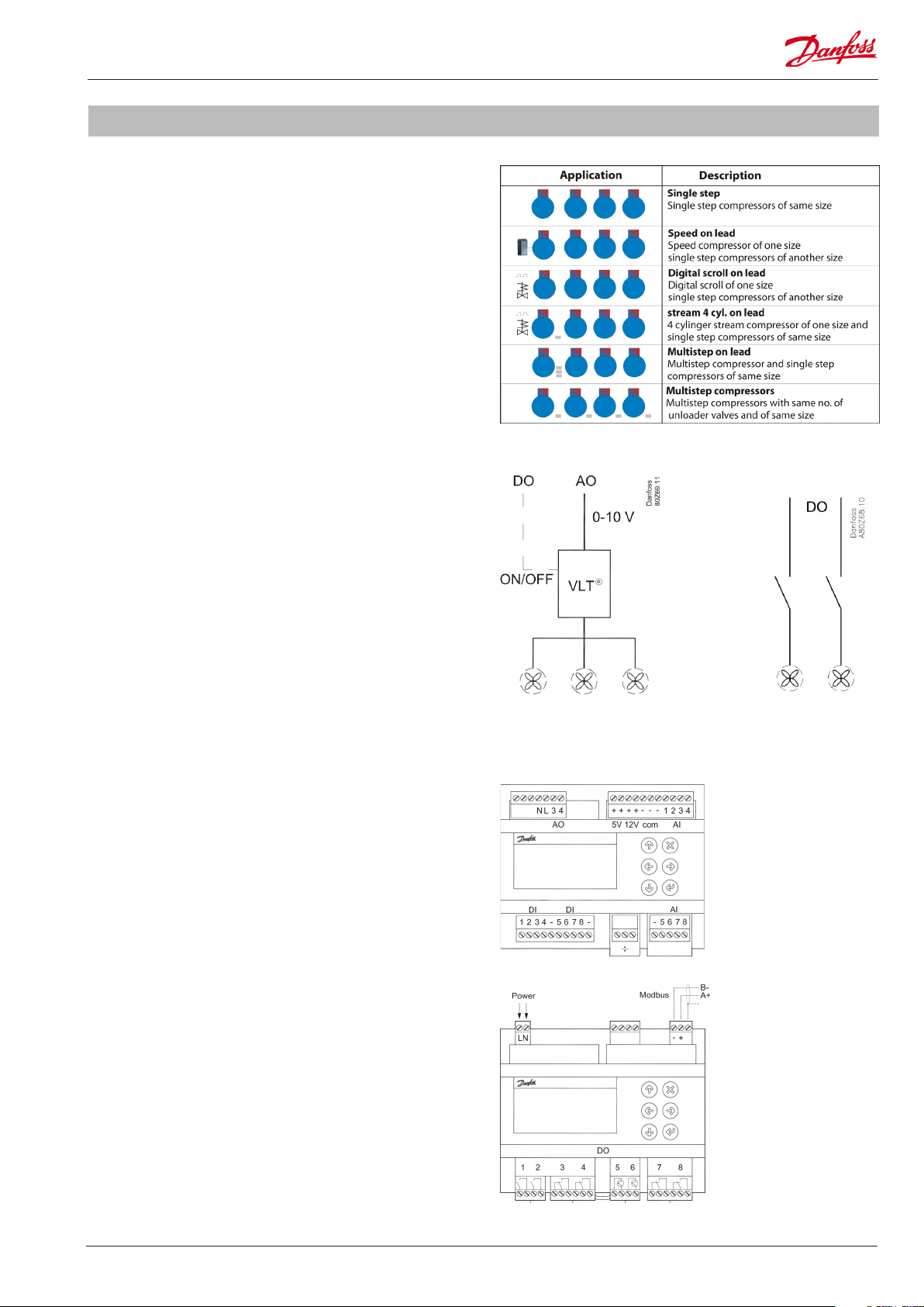
Compressor combinations
The compressor capacity can be controlled according to the
suction pressure Po or a media temperature sensor S4�
AK-PC 551 covers a variety of compressor combinations�
Condenser combinations
The condenser capacity can be controlled according to the
condensing pressure Pc or a media temperature sensor S7
The condenser can be controlled in two ways:
• Speed control of all fans
• Step control of single fans
Inputs and outputs
All in- and outputs of an AK-PC 551 controller can be congured
for various functions and signal types:
• 8 analogue inputs for pressure transmitters and temperature
sensors�
• 6 digital relay outputs for compressors, fans, alarm�
• 2 digital solid state outputs for PWM control of Digital scroll
or Stream compressor� If not used for this purpose they can
be used as normal relay outputs�
• 2 analogue outputs for speed control of compressors and
condenser fans�
Speed control of all fans Step control of all fans
AK-PC 551 Technical brochure RC8CF102 © Danfoss 08-2014 5
Basic Operation
Conguration and daily operation of AK-PC 551 is done via the
built-in display or via a remote connected display� The display
supports multiple languages and engineering units�
For a full description of the controller parameters please see the
manual RS8GY
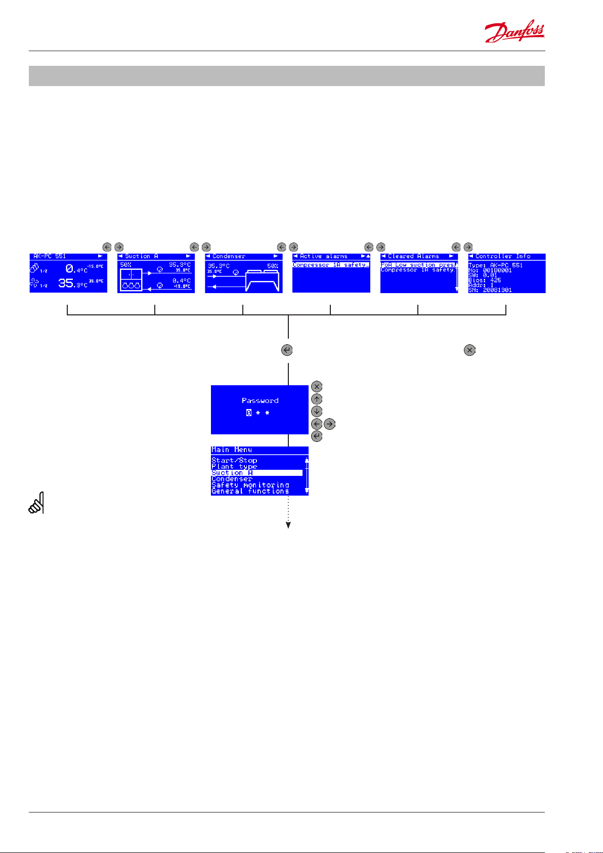
Status
Get an overview of how the system is running in the status
screens� Use the LEFT / RIGHT buttons to view the status screens�
Suction statusHome Condenser status Active alarms Cleared alarms Controller information
Password
Parameters and menus are protected by a
password that gives access on 3 dierent
user levels�
Level 0: See parameters (000)
Level 1: Change weekly schedule (100)
Level 2: Change control setpoints (200)
Level 3: Change conguration setpoints (300)
The password cannot be reset, so please
remember the (level 3) password�
Logout
Go to the "Home" screen and hold down the
X key for 5 seconds to logout�
Setup & service
In the main menu you will nd all control
parameters divided into sub menus�
From any status screen press ENTER for
2 sec� to access main menu
Press ESCAPE to go back to status
Press UP to decrease digit
Press DOWN to increase digit
Press LEFT / RIGHT to go to next / previous digit
Press ENTER to login
Press ESCAPE to
go one level back
6 Technical brochure RC8CF102 © Danfoss 08-2014 AK-PC 551
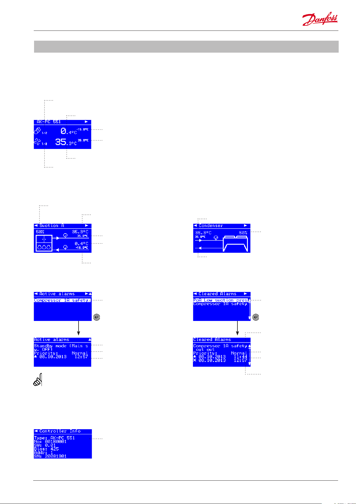
Basic Operation
The number of status screens and the presented data depends
upon the congured application�
Home
Number of compressors running
(1 of 2 compressors is running)
Suction control sensor readout
Suction reference
Condenser reference
Condenser control sensor readout
Number of fans running
(1 of 2 fans is running)
Suction status
Running compressor capacity
Condenser control sensor
Condenser status
Condenser control sensor
Condenser reference
Suction control sensor
Suction reference
Active alarms
Active alarm
Press ENTER to see
alarm details
Alarm text
Alarm priority
Alarm activated at
To clear an alarm press ESC (X) for 2 sec�
Running fan capacity
Condenser reference
Cleared alarms
? temperature
Cleared alarm
Press ENTER to see
cleared alarm details
Alarm text
Alarm priority
Alarm activated at
Alarm cleared at
Controller information
Technical controller information
like code number and software
version etc�
AK-PC 551 Technical brochure RC8CF102 © Danfoss 08-2014 7
Basic Operation
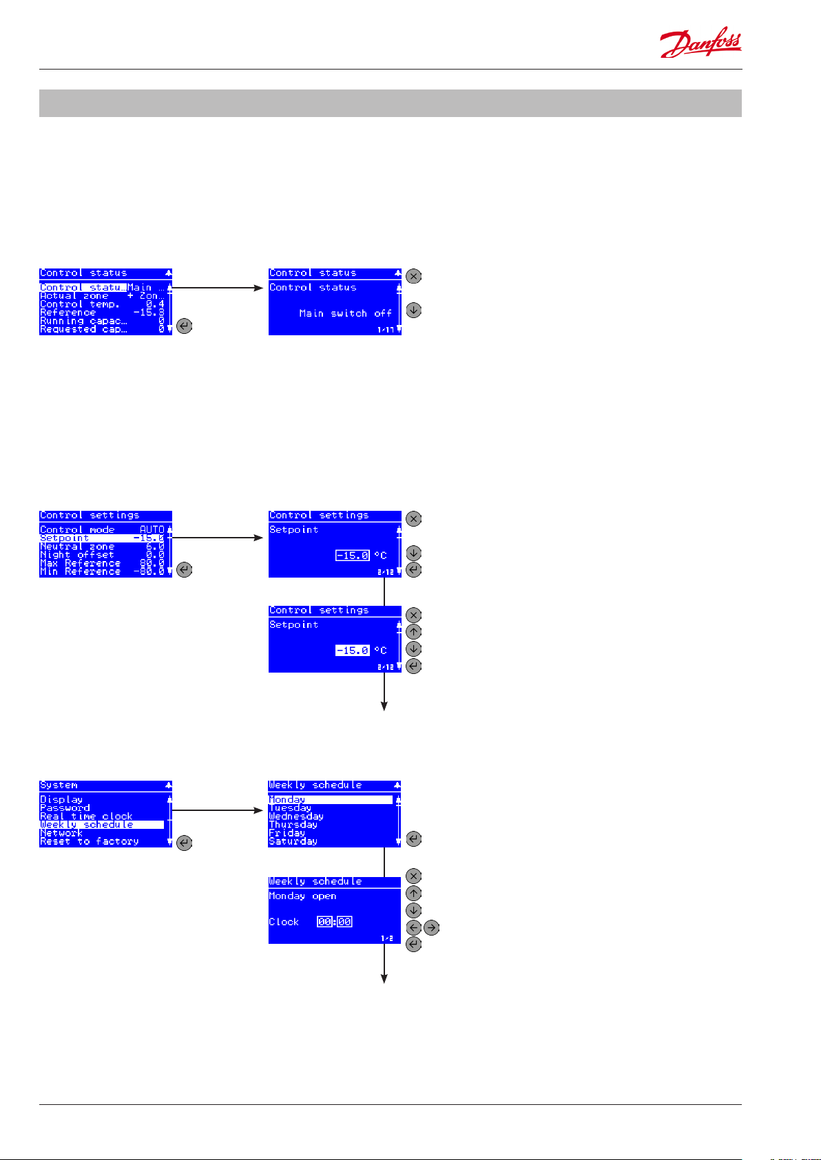
View parameters
The display will only present parameters that are valid for the
congured application e�g� if 4 compressors are selected only 4 are
showed�
A partly highlighted row indicates that a parameter can be viewed
and not changed�
Press ENTER
Control status menu
Change parameters
A full highlighted row indicates that a parameter can be changed�
A changable parameter has a frame around the setting�
to select
control
status
Control status readout
Press ESCAPE to go back one level
Press DOWN to see next parameter
Control settings menu
Day / night schedule
System menu
to select
setpoint
Press ENTER
to select
weekly
schedule
Setpoint readout
Setpoint selected
Weekly schedule
Monday open time
Press ESCAPE to go one level back
Press DOWN to see next parameter
Press ENTER to edit a parameterPress ENTER
Press ESCAPE to go one level back
Press UP to increace the setpoint
Press DOWN to decrease the setpoint
Press ENTER to save the setpoint
Press ENTER to select day
Press ESCAPE to go one level back
Press UP to increace the time
Press DOWN to decrease the time
Press LEFT / RIGHT to go to hour / minute
Press ENTER to save the setting
8 Technical brochure RC8CF102 © Danfoss 08-2014 AK-PC 551

First time start up
Conguration
After installation the controller must be congured for an
application� Once power is applied to the controller, the "Power
on" screen will appear�
Use one of the three options to congure the controller:
• Setup wizard
• Quick configuration
• Parametric setup
Setup wizard
Setup wizard is a step by step up and running guideline, setting
up inputs and outputs automatically�
Quick conguration
Quick conguration is a series of precongured applications,
setting up inputs and outputs automatically�
Parametric setup
Parametric setup is for the expert user, who wants to set each
parameter individually, adjust or netune settings�
Power on screen
Quick start
Press ENTER for 2 sec�
and enter password (300)
to access quick start
AK-PC 551 Technical brochure RC8CF102 © Danfoss 08-2014 9

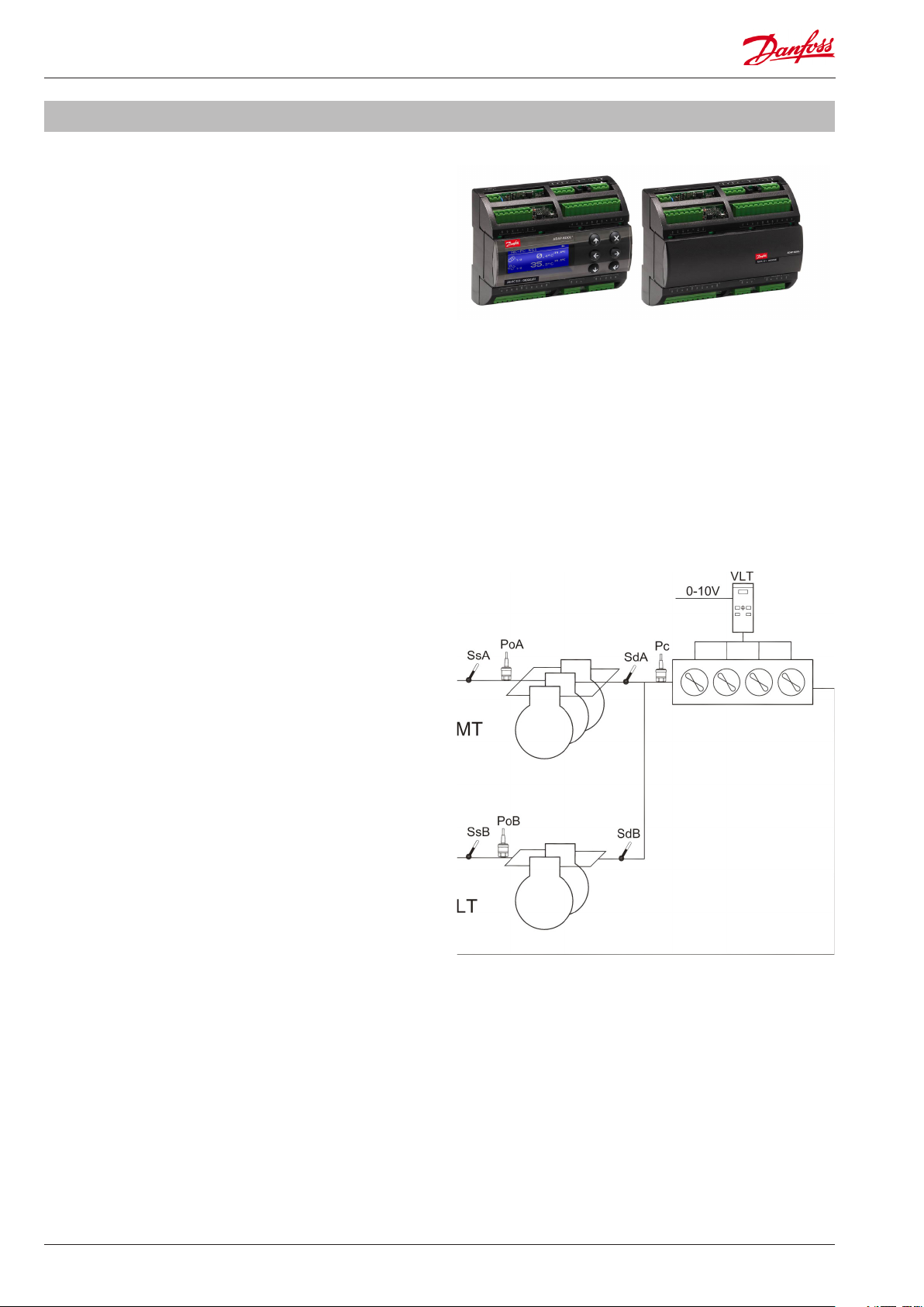
Example: Application
Application: Digital scroll
The conguration and daily operation of the AK-PC 551 will be
explained via an application example:
AK-PC 551 controls a refrigeration system with two suction
groups of compressors and a common air cooled condenser�
Refrigerant: R404A
Suction group MT:
1 digital scroll compressor
2 single step scroll compressors
Control according to suction pressure Po
Set point -15 °C
Monitoring of discharge temperature of digital scroll
Suction group LT:
2 single step scroll compressors
Control according to suction pressure Po
Set point -30°C
Condenser:
Speed control of 4 fans
Common safety monitoring of fans
Relay output for start/stop of VSD
Control according to condensing pressure Pc
Floating reference according to Sc3 outdoor temp�
10 Technical brochure RC8CF102 © Danfoss 08-2014 AK-PC 551

Example: Wiring Diagram
Electrical wiring
The electrical wiring is laid out according to the wizard rules for
assigning functions to the inputs and outputs
DO Function DI Function AO Function AI Function
DO1 Com� 1A DI1 Comp� 1A safety AO3 Fan VSD AI1 PoA suction pressure
DO2 Comp� 2A DI2 Comp� 2A safety AO4 AI2 PoB suction pressure
DO3 Comp� 3A DI3 Comp� 3A safety AI3 Pc condensing pressure
DO4 Comp� 1B DI4 Comp� 1B safety AI4 Sc3 outdoor temp�
DO5 Comp� 1A PWM DI5 Comp� 2B safety AI5 Sd Comp� 1A
DO6 Comp� 2B DI6 Fan safety AI6
DO7 Fan VSD DI7 AI7
DO8 DI8 AI8
DO8 DI8 AI8
Connection, lower level
Electrical diagram
Connection, upper level
AK-PC 551 Technical brochure RC8CF102 © Danfoss 08-2014 11

Example: Wizard
Wizard setup
In this example we will use the wizard to congure the controller�
Press ENTER for 2 sec�
and enter password (300)
to access quick start
Press ENTER
to select the
wizard
General
In the rst general screens you must select
how data are presented in the display�
Please note that the “Control setup unit”
decides whether the control set points are
presented in pressure units or temperature
units (saturated temperature)�
Press ESCAPE to
leave the wizard
Press ENTER to
start the wizard
Wizard screens: Settings:
Language: English
Control setup unit: Sat. temp
Temperature units: °C
Pressure units: Bar
Plant type
Select the overall application of the
controller and the refrigerant type�
Suction A and B
Set the compressor combination as well
as the compressor sizes, control sensor
and set point� The pressure range of the
pressure transmitter can be set�
Select plant type: 2 comp + 1 cond
Refrigerant type: R404A
Suction A
Po sensor max� range: 12.0 bar
Po sensor min� range: -1.0 bar
Setpoint: -15 °C
Compressor mode: Digital scroll
No� of compressors: 3
Lead compressor size: 5 kW
Comp� size: 5 kW
Suction B
Po sensor max� range: 12 bar
Po sensor min� range: -1.0 bar
Setpoint: -30 °C
Compressor mode: Single step
No� of compressors: 2
Comp� size: 3 kW
12 Technical brochure RC8CF102 © Danfoss 08-2014 AK-PC 551
Example: Wizard
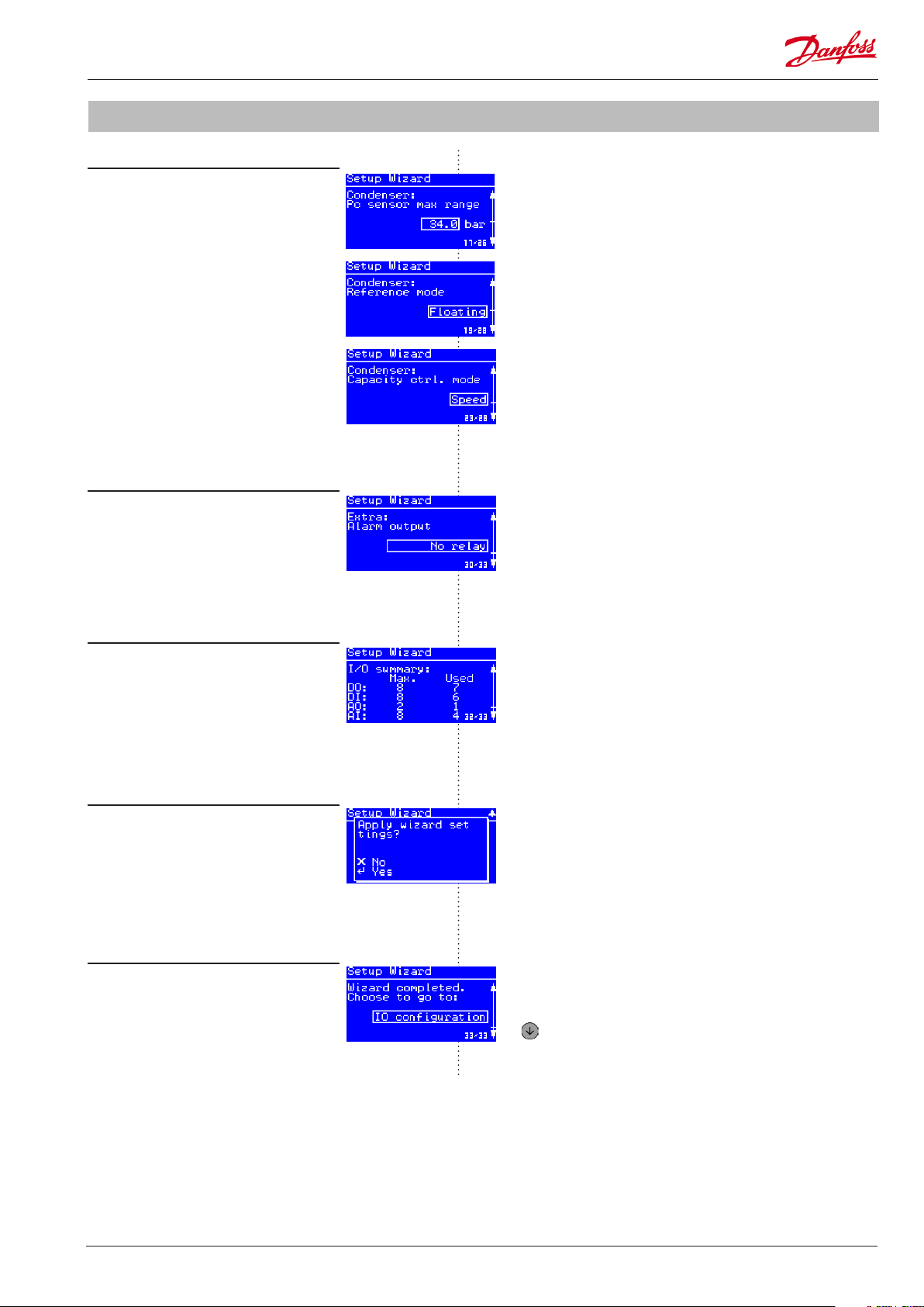
Condenser
Set the condenser control as well as control
sensor and reference settings� The pressure
range of the pressure transmitter can be
set�
Extra
Select whether to use an alarm relay and
Modbus network address�
Pc sensor max� range: 34.0 bar
Pc sensor min� range: -1.0 bar
Reference mode: Floating
Setpoint: 30 °C
Min� reference: 15 °C
Max� reference: 45 °C
Capacity ctrl� mode: Speed
No� of fans: 1
VSD Start via DO: Yes
Monitor fan safety: Common
Alarm output: No relay
Modbus address: 100
Summary
Get an overview of the inputs and outputs
generated by the wizard�
Apply wizard settings
Press ENTER to apply the wizard settings
to the controller including automatic
assignment requested inputs and outputs�
Next step
Select which main menu to go to� Press
DOWN to go to the selected menu�
It is recommended to check the IO (input /
output) conguration before starting the
controller�
Press DOWN to go to the selected menu and nish the
wizard
AK-PC 551 Technical brochure RC8CF102 © Danfoss 08-2014 13

Example: Check IO conguration
Wizard assignment of inputs and outputs (I/0)
Once the wizard is applied, the IO functions are automatically
assigned to hardware inputs and outputs�
The screens below shows how the IO functions are assigned
according to the example�
Press ENTER to select
Main menu IO conguration menu
Digital outputs Digital inputs Analog outputs Analog inputs
I/O conguration
Press ENTER to select
digital and analog I/O
Assignment of inputs and outputs
The table indicates rules for assignment of inputs and outputs via the wizard�
Digital outputs (DO1-DO8) Digital inputs (DI1-DI8) Analog outputs (AO3 – AO4) Analog inputs(AI1-AI8)
PWM outputs for capacity
control of Digital scroll or
Stream 4 compressor are placed
on the solid state relays DO5
and DO6
Starting from DO1: Fan safety inputs Speed control of condenser Pc condensing pressure is
Compressor start relays
followed by unloading valves
for respectively suction group
A and B
Condenser fan HP safety switch* S4A and S4B suction media
Injection ON for A/B * LP safety switch * S7 condenser media
Alarm relay Night setback * Sd komp� 1 discharge temp�
Compressor safety inputs for
respectively suction group A
and B
External Main switch (ON/
OFF) *
Heat recovery * Ss suction gas temperature for
Load shedding * Sd discharge temperature for
General alarm inputs 1-3 * Saux for general thermostat *
Speed control of compressor
for respectively suction group A
and B
PoA og PoB suctionpressure are
placed on AI1 and AI2
placed on AI3
Sc3 outdoor temperature is
placed on AI4
temperature sensors *
temperature sensor *
sensor for digital scroll/Stream
compressor for suction A and B
suction group A and B *
suction A and B *
* Special features to be enabled through conguration screens. Not part of the wizard setup.
14 Technical brochure RC8CF102 © Danfoss 08-2014 AK-PC 551

Example: Check IO conguration
IO conguration error
If you get an “IO conguration error” alarm after setting main
switch in ON position, the reasons can be:
• Not all enabled IO functions have been assigned to a
hardware input or output
• The number of enabled IO functions exceeds the number of
available inputs or outputs of the controller
IO summary
Go to Main menu -> IO Status -> IO summary
If the number of enabled IO functions exceeds the maximum
number supported by the hardware, an exclamation mark “!” will
be shown at the IO type in question� This means that you will have
to disable some of the IO functions via the conguration menus
of the suction groups and condenser in order not to exceed the
maximum available inputs or outputs�
If no exclamation mark is shown it means that at least one IO
function has not been assigned to a hardware input or output�
This means that you will have to go into the IO conguration
menu of each IO type, select a free input/output and select the
missing function (if a function is selectable this is the reason for
the IO conguration error alarm)�
Alarm:
IO conguration error
I/O summary
An exclamation mark is shown
when max. number of IO is
exceeded !
AK-PC 551 Technical brochure RC8CF102 © Danfoss 08-2014 15

Example: Add extra I/O
Add extra I/O
The wizard covers all basic functions of the AK-PC 551
pack controller� Additional features can be set through the
conguration screens of the suction group or the condenser�
In this example we will add a Sd discharge temperature
monitoring of both suction groups�
1. Enable Sd temperature monitoring in suction group A and B
Go to Main menu -> Suction A ->Conguration
2. Assign the two Sd discharge temperature sensors to free
analog inputs
Go to Main menu -> IO conguration of analog inputs (AI)
Conguration menu
Sd discharge temp.
3. Select the Sd A and Sd B discharge sensors for respectively
AI6 and AI7
Please notice that it is only functions that are enabled in the
suction/condenser conguration menus that are selectable in the
IO conguration�
PWM outputs for Digital scroll or Stream compressors can only be
selected on the solid state relays DO5 and DO6�
Pressure transmitters with current signals of 0-20mA or 4-20mA
are only supported on AI1-AI4�
If a function has been assigned to an input or output and the
same function has been deselected in the suction/condenser
conguration afterwards, the IO conguration will show an
exclamation mark at the function� This is done in order to show
that an IO point is occupied by a function which is not used by the
controller�
Analog inputs menu
Analog input (AI) no. 6
AI no. 6 function
Analog inputs
An exclamation mark is shown
when an IO point is occupied by
a function which is not used by
the controller.
In this situation you should either enable the function again in the
suction/condenser conguration menus or deselect the function
in the IO conguration�
16 Technical brochure RC8CF102 © Danfoss 08-2014 AK-PC 551
Example: Check I/O wiring
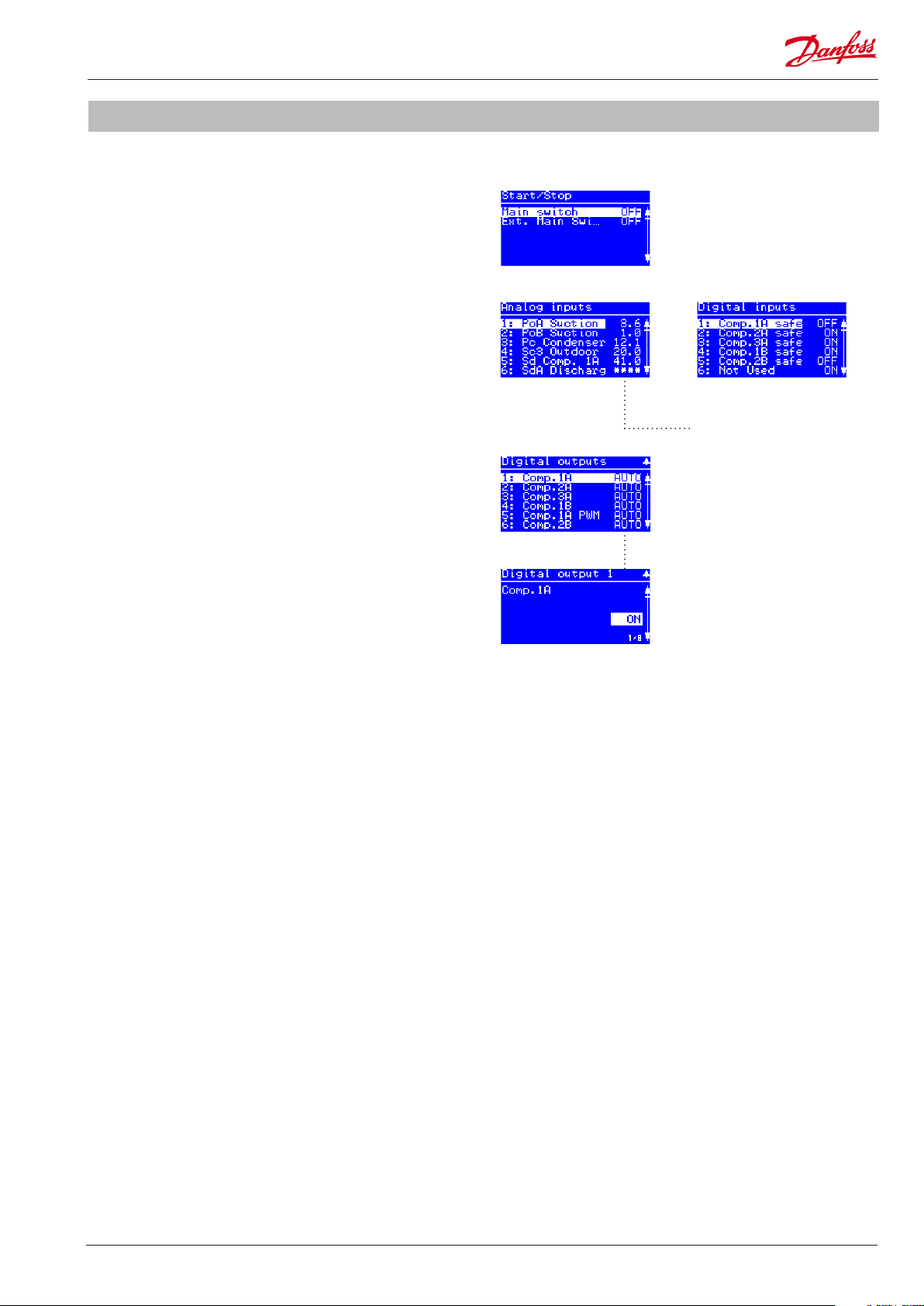
Initialize the controllers IO conguration
1. Set main switch in ON position
Go to Main menu -> Start/Stop
Set main switch ON
2. Check correct reading of inputs and outputs in the IO status
menus
Go to Main menu -> IO Conguration -> Analog/Digital inputs
Check correct status of all inputs�
3. Check correct wiring of the outputs via the IO manual
control menus
Go to Main menu -> IO Conguration -> Analog/Digital outputs
Check correct electrical wiring by manually overriding the
outputs�
Main switch menu
Analog inputs Digital inputs
The stars "****" indicates that
sensor error is detected or not
intialized (main switch ON).
Digital outputs
Digital output 1 ON
AK-PC 551 Technical brochure RC8CF102 © Danfoss 08-2014 17

Network setup
AK-PC 551 can be integrated into a Modbus communication
network� It is important that the installation of the communication
cable is done correctly� Also remember correct termination at
both ends of the cable�
Please refer to separate literature no� RC8AC
When AK-PC 551 is integrated into an ADAP-KOOL® network
with a system manager of the types AK-SC 355 or AK-SM 850 it is
important that some settings are set correctly�
1. Set unit of setpoints
Go to Main menu -> Plant type
The "Unit of setpoints" has to be set up before the controller is
scanned on the network� This is required in order for the front
end (AK-SC 355 or AK-SM 850) to present settings/readings in the
correct units (saturated temperature or pressure)�
2. Set network address
Go to Main menu -> System -> Network
3. Set the Modbus address in the range 1-199
- assuring that the selected address is not occupied by another
controller on the network�
Unit of setpoints
Network
4. Make sure that the Baud rate of the controller is set to “384”
(38400 bits per second)
5. Make sure that the serial mode is set “8E1”
When a network scan is carried out the controller will be identied
as:
• "AK-PC 551 - xxxx (MC250000)" - if the control setup unit is
saturated temperature�
• "AK-PC 551 - xxxx (MC250001)" - if the control setup unit is
pressure�
You can check the scanned controller in the front end in the menu
entry:
Conguration -> Network Nodes -> Scan Status
The AK-SM 850/AK-SC 355 must have software version G03�090 or
higher in order to support AK-PC 551� The software version can be
found in menu entry:
Info -> Information -> SW version
Modbus address and
Baudrate
Scanned controllers shown in the front end
18 Technical brochure RC8CF102 © Danfoss 08-2014 AK-PC 551

Example: Quick conguration
Quick conguration
As an alternative to the wizard, the controller can be set up by
selecting one of the precongurations dened in the controller�
Please refer to the application table (on page 18) for a full
description of all selectable precongurations and the associated
input and output wiring�
A quick conguration is done in ve steps:
1� Select a quick setting
2� Set language
3� Set unit of setpoints
4� Set refrigerant type
5� Set main switch on
1. Select quick setting
Go to Main menu -> Quick setup or select Quick settings at start
up�
In this example is used the preconguration number 17:
3CDA + 2CB+FS
Press ENTER to select
Quick Start menu
The Quick setup can
(after rst time setup) be
accessed from the main
menu.
2. Set language
Go to Main menu -> System -> Display
the quick settings
Quick setting
No plant type selected
After pressing ENTER the selection
goes back to "None" and the selected
preconguration is loaded into the
controller.
Plant type selected
Default is "English"
Language
3. Set unit of setpoints
Go to Main menu -> Plant type
Unit of setpoints
AK-PC 551 Technical brochure RC8CF102 © Danfoss 08-2014 19
Default is "Sat. Temp."

Example: Quick conguration
4. Set refrigerant type
Go to Main menu -> Plant type
By default the Quick conguration will assign AKS32R type
pressure transmitters for the suction and condensing pressure
with -1 to 12 bar and -1 to 34 bar pressure ranges�
It is recommended to check the IO (input / output) conguration
before starting the controller�
5. Set main switch ON
Go to Main menu -> Start/Stop -> Main switch
Default is "None"
Refrigerant menu
Refrigerant type R404A
Start/Stop menu
Main switch on
Application table
The application table shows the selectable precongurations
number, type of compressors and condensor fans� For more
details see the quick conguration table�
App. no. Display views Suction group A Suction group B Condenser
Speed Digital
(Scroll / steam)
17 3CDA + 2CB + FS 1 2 2 x
16 2CDA + 2CB + 3F 1 1 2 3
15 3CSA + 2CB + FS 1 2 2 x
14 2CSA + 2CB + 3F 1 1 2 3
13 4CA + 3CB + FS 4 3 x
12 3CA + 2CB + FS 3 2 x
11 2CA + 2CB + 3F 2 2 3
10 4CDA + FS 1 3 x
9 3CDA + FS 1 2 x
8 3CDA + 3F 1 2 3
7 2CDA + 2F 1 1 2
6 4CSA + FS 1 3 x
5 4CA + FS 4 x
4 4CA + 4F 4 4
3 3CSA + FS 1 2 x
2 3CA + FS 3 x
1 3CA + 3 F 3 3
0 None After selection the setting returns to "None"
1-step 1-step Step Speed
20 Technical brochure RC8CF102 © Danfoss 08-2014 AK-PC 551
Quick conguration table
Fan
safe�
Fan
safe�
Fan
safe�
Fan
safe�
safe�
Fan
Sw�
Sw�
Sw�
Sw�
C1A C2A C3A C1B C2B Main
C1A C2A C1B C2B Main
Digi
Digi
safe�
Fan
safe�
Fan
safe�
Fan
safe�
Fan
safe�
Fan
safe�
Fan
safe�
Fan
safe�
Fan
safe�
Fan
safe�
Fan
safe�
Fan
safe�
Sw�
Sw�
Sw�
Sw�
Sw�
Sw�
Sw�
Sw�
Sw�
Sw�
Sw�
Sw�
C1 C2 C3 C4 Main
C1 C2 C3 Main
C1 C2 C3 Main
C1 C2 Main
Digi
Digi
Digi
Digi
On/O Analog Analog Digital
DO1 DO2 DO3 DO4 DO5 DO6 DO7 DO8 AO3 AO4 AI1 AI2 AI3 AI4 AI5 AI6 AI7 AI8 DI1 DI2 DI3 DI4 DI5 DI6 DI7 DI8
PoA PoB Pc Sc3 SdA
Alarm Fan
C2B Fan
Speed
VSD
Fan1 Fan2 Fan3 PoA PoB Pc Sc3 SdA
PWM
PWM
PoA PoB Pc Sc3 C1A C2A C3A C1B C2B Main
Fan
Alarm C1A
PoA PoB Pc Sc3 C1A C2A C1B C2B Main
Speed
Speed
VSD
PoA PoB Pc Sc3 C1A C2A C3A C4A C1B C2B C3B Fan
Speed
PoA PoB Pc Sc3 C1A C2A C3A C1B C2B Main
Speed
Alarm Fan
Speed
VSD
PoA Pc Sc3 SdA
Alarm Fan
Fan
PoA Pc Sc3 SdA
Speed
Alarm Fan
VSD
Fan
PWM
Speed
VSD
Fan2 Fan3 Alarm PoA Pc Sc3 SdA
PWM
PWM
Alarm PoA Pc Sc3 SdA
PWM
PoA Pc Sc3 C1 C2 C3 C4 Main
Fan
Alarm C1
PoA Pc Sc3 C1 C2 C3 C4 Main
Speed
Speed
Alarm Fan
VSD
Speed
VSD
PoA Pc Sc3 C1 C2 C3 Main
Fan
Alarm C1
PoA Pc Sc3 C1 C2 C3 Main
Speed
Speed
Alarm Fan
VSD
Speed
VSD
App. no. Display views Outputs Inputs
17 3CDA + 2CB + FS C1A C2A C3A C1B C1A
16 2CDA + 2CB + 3F C1A C2A C1B C2B C1A
15 3CSA + 2CB + FS C1A C2A C3A C1B C2B Fan
14 2CSA + 2CB + 3F C1A C2A C1B C2B Fan1 Fan2 Fan3 Alarm C1A
13 4CA + 3CB + FS C1A C2A C3A C4A C1B C2B C3B Alarm Fan
12 3CA + 2CB + FS C1A C2A C3A C1B C2B Fan
11 2CA + 2CB + 3F C1A C2A C1B C2B Fan1 Fan2 Fan3 Alarm PoA PoB Pc Sc3 C1A C2A C1B CB2 Main
10 4CDA + FS C1 C2 C3 C4 C1
9 3CDA + FS C1 C2 C3 C1
8 3CDA + 3F C1 C2 C3 Fan1 C1
7 2CDA + 2F C1 C2 Fan1 Fan2 C1
6 4CSA + FS C1 C2 C3 C4 Fan
5 4CA + FS C1 C2 C3 C4 Fan
4 4CA + 4F C1 C2 C3 C4 Fan1 Fan2 Fan3 Fan4 PoA Pc Sc3 C1 C2 C3 C4 Main
3 3CSA + FS C1 C2 C3 Fan
2 3CA + FS C1 C2 C3 Fan
1 3CA + 3 F C1 C2 C3 Fan1 Fan2 Fan3 Alarm PoA Pc Sc3 C1 C2 C3 Main
0 None
AK-PC 551 Technical brochure RC8CF102 © Danfoss 08-2014 21

Frequently asked questions (FAQ)
Question Solution
How to connect
variable speed drive
(VSD)?
The analogue outputs AO3 and AO4 of the AK-PC 551 pack
controller is galvanic separated from the other inputs and outputs
of the controller� So if the AK-PC 551 controller is ordered for 24Vac
supply voltage, you can use the same 24Vac transformer for power
supply of the controller and for supply of the analogue outputs�
It is recommended to use a double isolated transformer (Class II) as
this type does not need to be connected to protective earth on the
secondary side� This will prevent any ground loops between the
AK-PC 551 pack controller and the variable speed drive connected
to AO3 or AO4�
Example: Variable speed drive connected
to AO3
How to connect the
PWM valve of a digital
scroll compressor?
The Pulse Width Modulated valve (PWM) of a digital scroll
compressor must be connected to one of the solid state relays
(SSR) of AK-PC 551 - which are the outputs DO5 or DO6� The PWM
valve function cannot be selected for any of the other digital
outputs�
The PWM valve of the digital scroll compressor works in such a
way that when voltage is supplied to the valve, the digital scroll
compressor is unloaded and when no voltage is supplied to the
valve, the digital scroll compressor is loaded�
When the PWM valve signal is selected for DO5 or DO6, the
polarity of the output signal is by default inverted and thereby
the PWM valve of the digital scroll compressor can be connected
directly to the AK-PC 551 without any intermediate relays�
Example: Wiring of PWM valve of digital
scroll compressor to DO5/DO6 of AK-PC
551
22 Technical brochure RC8CF102 © Danfoss 08-2014 AK-PC 551

Question Solution
How to start and stop
an AK-PC 551 pack
controller?
The AK-PC 551 controller has two options for start/stop of control�
Parameter set via the display:
The parameter “Main switch” is used to start/stop control (see
screen dumps)
Optional start/stop via digital input signal:
The AK-PC 551 controller can also be controlled via a digital input
signal� This function is enabled in the Plant type menu and then
set up in the IO conguration of digital inputs�
If any of the two “Main switch” signals is in OFF position, the AK-PC
551 will stop all control, set all outputs in standby position and
clear all active alarms�
At the same time the controller will generate a special alarm
“Standby mode alarm” in order to indicate that the controller has
been stopped�
How to setup and
connect a pressure
transmitter with 0-20
mA or 4-20 mA current
signals?
How does the wizard
assign functions to
inputs and outputs?
Pressure transmitters with current output signals of 0-20 mA
or 4-20 mA MUST be connected to one of the analogue input
terminals AI1, AI2, AI3 or AI4�
The signal type and signal range of the pressure transmitter is
setup in the “IO conguration” menu for analogue inputs�
In the example the suction pressure signal for suction group A, has
been selected for analogue input 1 and the signal type is selected
as “4-20mA”� Please be aware that the minimum and maximum
pressure ranges are set in relative pressure�
The power supply for pressure transmitters with current signal
must be connected to the 12 Vdc terminal of AK-PC 551� The signal
wire must be connected to the analogue input pin in question�
If the AK-PC 551 controller is congured via the wizard, the
required functions are automatically assigned to inputs and
outputs�
At the end of the Setup wizard, the user is asked whether the
controller should apply the settings made in the wizard� Please be
aware that the wizard will overwrite all previous congurations, if
the user selects to apply the wizard settings�
Once the user selects to apply the wizard settings, the required
functions are assigned to inputs and outputs based on simple
priority rules� The rules can be seen in detail in the paragraph
“Example: Check IO conguration”
AK-PC 551 Technical brochure RC8CF102 © Danfoss 08-2014 23

Question Solution
How to connect a
remote display?
The remote MMIGRS2 display is connected to the controller via a
cable that can be ordered with dierent lengths�
When connecting the remote display, please remember to make a
short circuit of the two rightmost terminals on the terminal block
to the left of the cable connection – please refer to drawing�
When are alarms
cleared?
Normally alarms are automatically cleared as soon as the alarm
condition is cleared�
However, some safety alarms require that a safety restart delay has
to expire before the alarm condition is cleared and normal control
is resumed� This goes for the following safety alarms:
• High condensing pressure
• Low suction pressure
• High discharge temperature
Furthermore sensor alarms have a clearance delay of 10 minutes
(default), which means that the sensor has to be OK for 10 minutes
before the alarm is cleared� However normal control procedure will
be resumed as soon as the sensor signal is OK� The reason for the
delay is to avoid numerous alarms if a sensor has a bad electrical
connection�
Alarms can also be cleared manually by entering the alarm detail
picture and pressing the “X” button for 3 seconds� If the alarm
condition of a manually cleared alarm is still active the alarm will
be raised again�
Press the X (escape) button for 3 seconds
to clear alarms manually
Danfoss can accept no responsibility for possible errors in catalogues, brochures and other printed material� Danfoss reserves the right to alter its products without notice� This also applies to products
already on order provided that such alternations can be made without subsequential changes being necessary in specications already agreed�
All trademarks in this material are property of the respecitve companies� Danfoss and Danfoss logotype are trademarks of Danfoss A/S� All rights reserved�
24 Technical brochure RC8CF102 © Danfoss 08-2014 AK-PC 551
ADAP-KOOL®
 Loading...