

Page 1
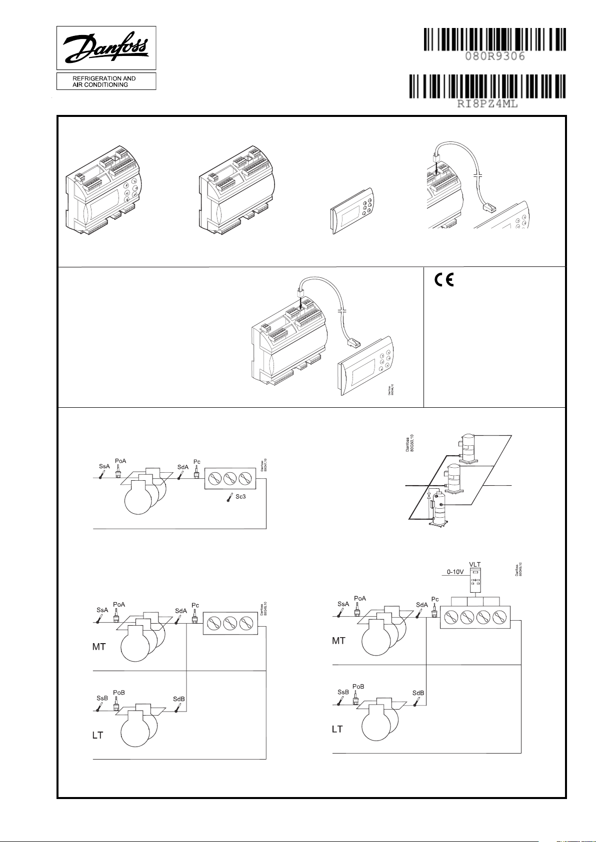
Identication
Instructions
AK-PC 551
1.5 m: 080G0075
3.0 m: 080G0076
080G0281 = 230 V a.c. 20 VA
080G0283 = 24 V a.c. / d.c. 17 VA
Kit
080G0282 = 080G0321 + 080G0294 + 080G0075
(230 V)
080G0288 = 080G0326 + 080G0294 + 080G0075
(24 V)
Principle
080G0321 = 230 V a.c. 20 VA
080G0326 = 24 V a.c. / d.c. 17 VA
MMIGRS2: 080G0294
1,5 m
IP 20
-20 - 60°C
(0 - 140°F)
RH max. 90% non condensing
RI8PZ4ML 2015-06
Page 2
ENGLISH
Connection, lower level
DO DO1 DO2 DO3 DO4 DO5 DO6 DO7 DO8 Σ 1-8
I Max. 10 A
U All 24 V or all 230 V a.c.
(3,5)
10 A
(3,5)
6 A
(4)
6 A
(4)
0.5 A
min. 50 mA
Io < 1.5 mA
0.5 A
min. 50 mA
Io < 1.5 mA
6 A
(4)
6 A
(4)
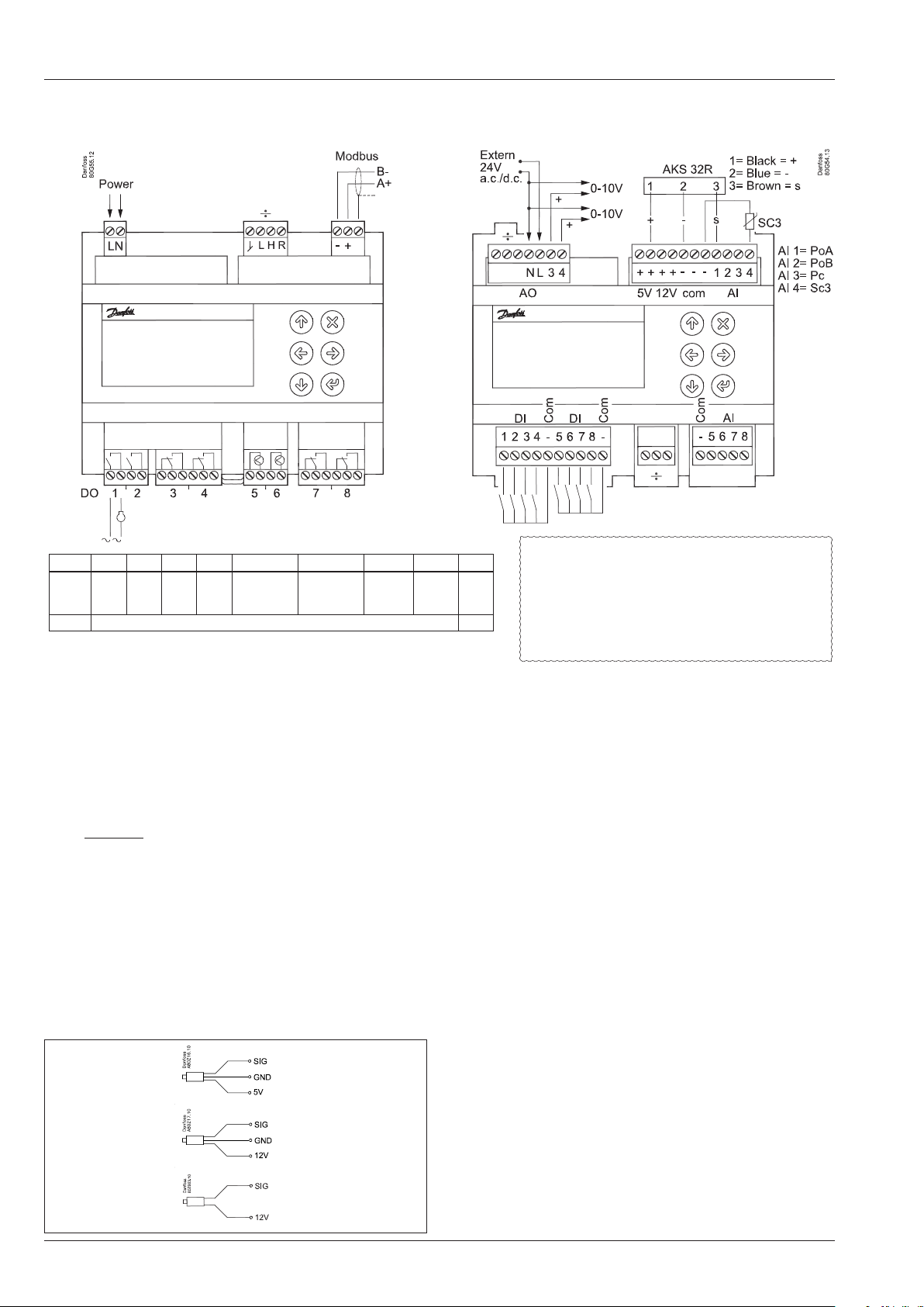
Connection, upper level
Separate
supply!
32 A
Warning
The supply voltage of AI may not share
the signal with other controllers.
Electric noise
Signal cables for sensors, DI inputs, data communication
and display must be kept separate from high voltage
(230 V) electric cables:
- Use separate cable trays
- Keep a distance between high voltage and signal cables
of at least 10 cm
- Cables longer than 3 m at the DI input should be avoided
Supply Voltage.
The supply voltage is either 24 V or 110-230 V. See the label on
the reverse side of the controller.
÷ = Plugs normally not used
However, if connecting to an external display, a jumper must
be inserted between the connections "H" and "R".
Modbus
It is important that the installation of the data communication
cable be done correctly. Cf. separate literature No. RC8AC.
Remember termination at the bus termination.
DO - Digital outputs, 8 pcs. DO1 - DO8
DO5 and DO6 are solid state relays.
The relays are de-rated to the specied values.
If an alarm relay is dened, it will be driven under normal operation and it will drop in the event of alarms and insucient
power to the controller.
AKS 32R
AKS 32
AKS 33
10-90% ratiometric
1-5 V
0-20mA
4-20mA
AO - Analogue output, 2 pcs. AO3 - AO4
Must be used when using a frequency converter or EC motors.
Connect 24 V on N and L (separate supply). Avoid earth fault
current. Use double-insulated transformer. The secondary side
must not be earthed.
Obtain 0-10 volts from terminals N and AO3, respectively N and
AO4. PAY ATTENTION TO THE POLARITY of N.
AI - Analogue inputs, 4 pcs. AI1 - AI4
Pressure transmitters
• Ratiometric: 10-90% of supply, AKS 32R
• Signal: 1-5 V, AKS 32
• Power: 0-20 mA / 4-20 mA, AKS 33 (supply = 12 V)
Temperature sensor
• Pt 1000 ohm, AKS 11 or AKS 21.
• NTC 86K ohm @ 25°C, from digital scroll.
Factory settings
AI1=PoA, AI2=PoB, AI3=Pc, AI4=Outdoor temperature SC3.
DI - Digital switch inputs, 8 pcs. DI1 - DI8
The connection may be a shut-down or interruption function.
Select what is to be activated during conguration.
÷ = Plugs normally not used
AI - Analogue inputs, 4 pcs. AI5 - AI8
Pressure transmitters
• Ratiometric: 10-90% of supply, AKS 32R
• Signal: 1-5 V, AKS 32
Temperature sensor
• Pt 1000 ohm, AKS 11 or AKS 21.
• NTC 86K ohm @ 25°C, from digital scroll
2 Instructions RI8PZ4ML © Danfoss 06/2015 AK-PC 551
Page 3
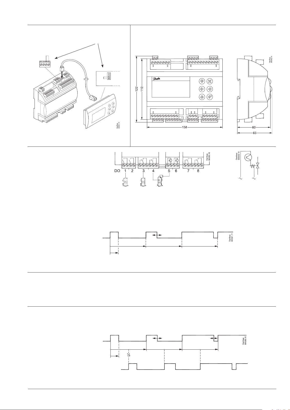
External display Dimensions
Termination
Connect H-R
Important!
Termination
Connect H-R
The capacity from the
digital scroll compressor
Only DO5 or DO6
The capacity is divided into period times as "PWM period time". 100% capacity is delivered when cooling takes place for the whole
period.
An o time is required by the capacity control valve within the period and an on time is also permitted. There is "no cooling" when the
valve is on.
The controller itself calculates the capacity needed and will then vary it according to the cut-in time of the capacity control valve.
A limit is introduced if low capacity is needed so that the cooling does not go below 10%. This is because the compressor can cool
itself. This value can be increased if necessary.
Refrigeration / No refrigeration
Period time
Min. capacity
Copeland Stream compressor
The signal can also be used to control one stream compressor with one unloading valve (4 cylinders version).
The compressor capacity is distributed by up to 50% for one relay and the remaining 50-100% for the unloader. The unloader is connected to DO5 or DO6.
Bitzer CRII
The pulse signal can also be used to control one of the CRII with 2 unloaders (4 cylinders version).
Compressor capacity can be controlled from 10 to 100% depending on the pulsation of the unloaders. The unloader is connected to
DO5 or DO6.
Unloader 1
Unloader 2
Unloader 2 follows unloader 1
but is oset a ½ period.
AK-PC 551 Instructions RI8PZ4ML © Danfoss 06/2015 3
Page 4
Português
Conexão, nível inferior
Separar
alimentação!
DO DO1 DO2 DO3 DO4 DO5 DO6 DO7 DO8 Σ 1-8
I Max. 10 A
U Tudo 24 V ou tudo 230 V CA
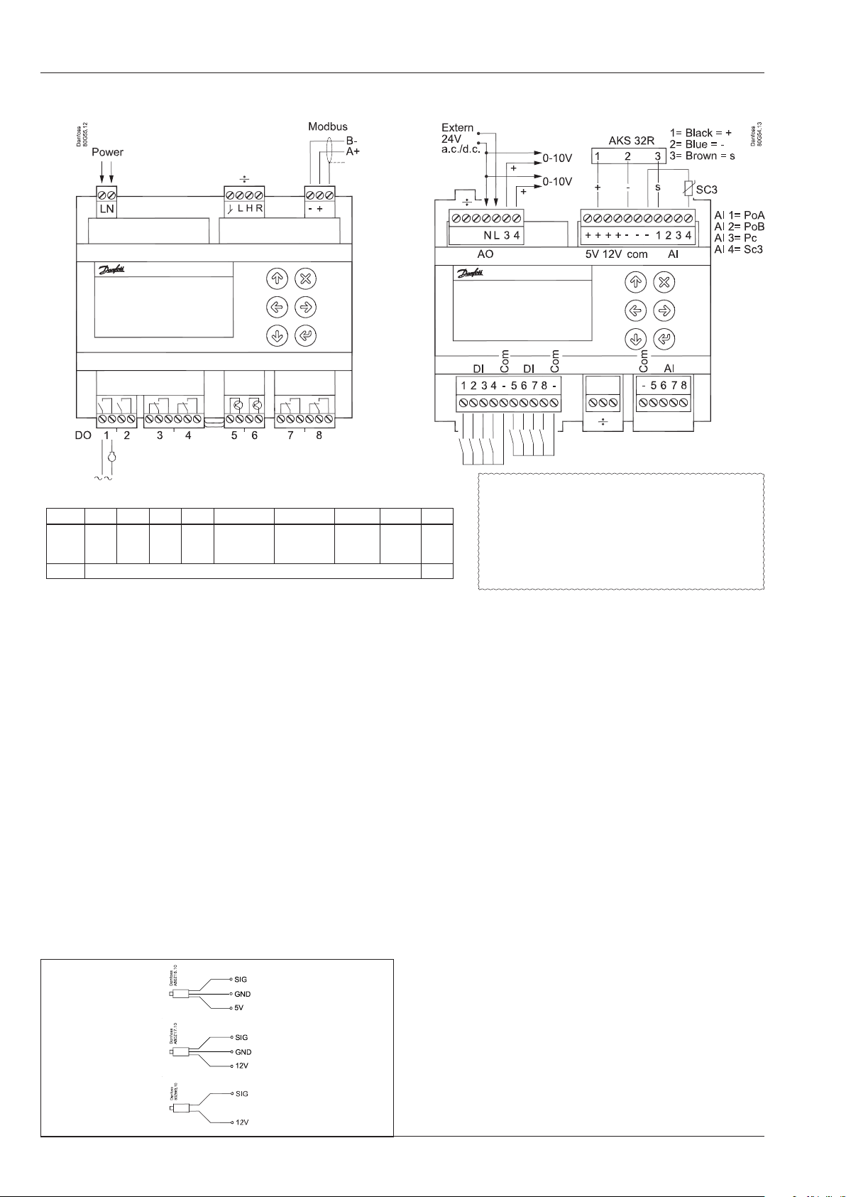
Fonte de alimentação
(3,5)
10 A
(3,5)
6 A
(4)
6 A
(4)
0.5 A
min. 50 mA
Io < 1,5 mA
0.5 A
min. 50 mA
Io < 1,5 mA
6 A
(4)
6 A
32 A
(4)
AO - saída analógica, 2 pcs. AO3 - AO4
A tensão de alimentação é de 24 V ou de 110-230 V. Consulte a
etiqueta no reverso do controlador.
÷ = Plugues normalmente não utilizados
Entretanto, no caso de conectar com um display externo, um
jumper deverá ser inserido entre as duas conexões "H" e "R"
Modbus
É importante que a instalação do cabo de comunicação de
AI - entradas analógicas, 4 pcs. AI1 - AI4
dados seja feita corretamente.
Consulte a literatura separada nº RC8AC…
Lembre-se: terminação na terminação do barramento.
DO - saídas digitais, 8 pcs. DO1 - DO8
DO5 e DO6 são relés de estado sólido.
É feito derate dos relés para os valores especicados.
Caso um relé de alarme seja denido, ele será acionado
durante a operação normal e desarmará em caso de alarmes
e de tensão insuciente para o controlador.
Conexão, nível superior
Advertência
A tensão de alimentação do AI pode não compartilhar o sinal com outros controladores.
Ruído elétrico
Cabos de sinal para sensores, entradas DI, comunicação de
dados e display devem ser mantidos separados de outros
alta tensão (230 V) cabos elétricos:
- Use condutores de cabos separados
- Manter uma distância entre os cabos de alta tensão e de
sinal de pelo menos 10 cm
- Cabos de extensão superior a 3 m na entrada DI devem
ser evitados
Deverão ser utilizadas ao usar um conversor de frequência ou
motores EC.
24 V conectado no N e L (separar alimentação).. Evite corrente de falha do terra. Use um transformador com isolamento
duplo. O lado secundário não deve ser aterrado.
Obtenha 0-10 volts dos terminais N e AO3, respectivamente N
e AO4. PRESTE ATENÇÃO À POLARIDADE de N.
Transmissores de pressão
• Ratiometric: 10-90% do fornecimento, AKS 32R
• Sinal: 1-5 V, AKS 32
• fonte de alimentação: 0-20 mA / 4-20 mA, AKS 33 (fornecimento = 12 V)
Sensor de temperatura
• Pt 1000 ohm, AKS 11 ou AKS 21.
• NTC 86K ohm @ 25°C, a partir de digital scroll.
Congurações de fábrica
AI1=PoA, AI2=PoB, AI3=Pc, AI4=temperatura exterior SC3.
DI - Entradas digital chave, 8 pcs. DI1 - DI8
A conexão pode ser um desligamento ou função de interrupção.
Selecione o que deverá ser ativado durante a conguração.
AKS 32R
10-90% ratiometric
÷ = Plugues normalmente não utilizados
AI - entradas analógicas, 4 pcs. AI5 - AI8
Transmissores de pressão
AKS 32
1-5 V
• Ratiometric: 10-90% da alimentação, AKS 32R
• Sinal: 1-5 V, AKS 32
Sensor de temperatura
AKS 33
0-20mA
4-20mA
• Pt 1000 ohm, AKS 11 ou AKS 21.
• NTC 86K ohm @ 25°C, a partir de digital scroll.
4 Instructions RI8PZ4ML © Danfoss 06/2015 AK-PC 551
Page 5

Display externo Dimensões
Terminação
conectado H-R
Importante!
Terminação
conectado H-R
A capacidade do compressor
de rolagem digital
Somente para DO5 ou DO6
A capacidade é dividida em períodos de tempo. É fornecida 100% da capacidade quando o resfriamento acontece durante todo o período.
Um tempo desligado é necessário para a válvula de controle de capacidade, dentro do período e um tempo ligado também é permitido. Não há “resfriamento” quando a válvula estiver ligada.
O controlador por si próprio calcula a capacidade necessária e então irá variá-la de acordo com o tempo de ligar da válvula de controle
de capacidade.
Um limite é introduzido se uma baixa capacidade for necessária de modo que o resfriamento não caia para baixo de 10%. Isto é porque
o compressor pode resfriar-se a si próprio. Esse valor poderá ser aumentado, se necessário.
Refrigeração / Não há refrigeração
Período de tempo
Min. Capacidad
Copeland Compressor de uxo
O sinal de também pode ser usado para controlar um compressor de uxo com 1 válvula de alívio de pressão (versão com 4 cilindros).
A capacidade do compressor é distribuída por até 50% para um relé e os restantes 50-100% para o descarregador. O descarregador
está conectado em DO5 ou DO6.
Bitzer CRII
O sinal de pulso também pode ser utilizado para controlar um dos CRII com 2 descarregadores (versão com 4 cilindros).
A capacidade do compressor pode ser controlada de 10 a 100%, dependendo da pulsação dos descarregadores. O descarregador está
ligado a DO5 ou DO6.
Descarregador 1
Descarregador 2
O descarregador 2 segue o
descarregador 1, mas tem ½
período de deslocamento.
AK-PC 551 Instructions RI8PZ4ML © Danfoss 06/2015 5
Page 6

DEUTSCH
Verbindung, untere Ebene Verbindung, obere Ebene
Separate
versorgung!
Funkenstörung
DO DO1 DO2 DO3 DO4 DO5 DO6 DO7 DO8 Σ 1-8
I Max. 10 A
U Alle 24 V oder alle 230 V a.c.
Versorgungsspannung
(3.5)
10 A
(3.5)
6 A
(4)
6 A
(4)
0.5 A
min. 50 mA
Io < 1,5 mA
0.5 A
min. 50 mA
Io < 1,5 mA
6 A
(4)
6 A
32 A
(4)
AO - Analoge Ausgänge, 2 Stück AO3 - AO4
Die Versorgungsspannung beträgt entweder 24V oder 110 bis
230V. Siehe dazu das Schild auf der Rückseite des Reglers.
÷ = Stopfen werden im Normalfall nicht verwendet
Wenn jedoch eine Verbindung zu einem externen Display
hergestellt wird, muss eine Steckbrücke zwischen den beiden
Anschlüssen "H" und "R" eingesteckt werden.
Modbus
Bitte beachten, dass die Installation des Datenkommunikati-
AI - Analoge Eingänge, 4 Stück AI1 - AI4
onskabels korrekt vorgenommen wird.
Siehe separate Literatur Nr. RC8AC.
Denken Sie an die Terminierung an der Busterminierung.
DO - Digitale Ausgänge, 8 Stück DO1 - DO8
DO5 und DO6 sind Halbleiterrelais.
Die Leistung der Relais ist auf die angegebenen Werte reduziert.
Wenn ein Alarmrelais deniert ist, wird es unter Normalbetrieb
angetrieben werden, und es wird im Fall von Alarmen und ungenügender Leistung an den Regler fallen.
AKS 32R
10-90% ratiometric
DI - Digitale switch Eingänge, 8 Stück DI1 - DI8
Er muss verwendet werden, wenn Frequenzwandler oder ECMotoren zum Einsatz kommen.
Schließen Sie 24 V an N und L an (separate versorgung). Vermeiden Sie Erdschlussströme. Verwenden Sie doppelt isolierte
Transformatoren. Die Sekundärseite darf nicht geerdet sein.
Beziehen Sie 0-10Volt von den Terminals N und AO3 beziehungsweise N und AO4. ACHTEN SIE AUF DIE POLARITÄT von N.
Druckmessumformer
• Ratiometrisch: 10-90 % der Versorgung, AKS 32R
• Signal: 1-5 V, AKS 32
• Strom: 0-20 mA / 4-20 mA, AKS 33 (Versorgung = 12 V)
Temperaturfühler
• Pt 1000 ohm, AKS 11 oder AKS 21.
• NTC 86K ohm @ 25°C, von digital scroll.
Werkseinstellung
AI1=PoA, AI2=PoB, AI3=Pc, AI4=Aussentemperatur SC3.
Die Verbindung kann eine Abschaltfunktion oder eine Unterbrechungsfunktion sein. Wählen Sie aus, was während der Konguration aktiviert werden soll.
÷ = Stopfen werden im Normalfall nicht verwendet
Signalkabeln für Fühlern, DI-Eingängen, Datenkommunikation und Display sind getrennt von Hoch Spannungs (230
V) Elektrokabeln zu verlegen:
- Separate Kabeltröge verwenden.
- Zwischen den Hochspannungs- und Signal-Kabeln einen
Abstand von mindestens 10 cm halten.
- Bei DI-Eingängen Kabel länger als 3 m vermeiden.
Achtung
Die Versorgungsspannung des AI kann das
Signal nicht mit anderen Reglern teilen.
AI - Analoge Eingänge, 4 Stück AI5 - AI8
AKS 32
1-5 V
Druckmessumformer
• Ratiometrisch: 10-90 % der Versorgung, AKS 32R
• Signal: 1-5 V, AKS 32
AKS 33
0-20mA
4-20mA
Temperaturfühler
• Pt 1000 ohm, AKS 11 oder AKS 21.
• NTC 86K ohm @ 25°C, von digital scroll
6 Instructions RI8PZ4ML © Danfoss 06/2015 AK-PC 551
Page 7

Externes Display Dimensionen
Terminierung
Anschluss H-R
Wichtig!
Terminierung
Anschluss H-R
Die Leistung aus dem
Digital Scroll Verdichter
Nur DO5 oder DO6
Die Leistung wird als „PWM period time“ durch die Anzahl der Perioden geteilt. 100% Leistung wird erbracht, wenn während der gesamten Periode gekühlt wird.
Innerhalb der Periode ist für das Bypass-Ventil ein Ausschalten erforderlich, ein Einschalten ist ebenfalls gestattet. Wenn das Ventil eingeschaltet ist, ndet „keine Kühlung“ statt.
Der Regler selbst berechnet die erforderliche Leistung und passt sie dann entsprechend der Zuschaltung des Bypass-Ventils an.
Wenn eine niedrige Leistung benötigt wird, damit die Kühlung nicht unter 10 % sinkt, wird ein Grenzwert eingerichtet. Grund hierfür ist
die Tatsache, dass der Verdichter sich selbst kühlen kann. Der Wert kann bei Bedarf weiter erhöht werden.
Kühlung
Keine Kühlung
Period zeit
Min. Leistung
Copeland Stream-Verdichter
Das Puls-signal kann auch dazu verwendet werden, um einen Stream-Verdichter mit einem Entlastungsventil zu regeln. (4 Zylinder
Version)
Die Verdichterleistung wird um bis zu 50% auf ein Relais geleitet, die restlichen 50bis 100% auf das Entlastungsventil. Das Entlastungsventil ist mit einem DO5 oder einem DO6 verbunden.
Bitzer CRII
Das Puls-signal kann auch dazu verwendet werden, um einen CRII-Verdichter mit zwei Entlastungsventile zu regeln. (4 Zylinder Version)
Die Verdichterleistung kann von 10 bis 100% regeln abhängig von der Pulsierung der Entlastungsventile. Die Entlastungsventile sind mit
einem DO5 oder einem DO6 verbunden.
Entlasung 1
Entlasung 2
Entlasung 2 folgt Entlasung 1
aber wird mit einer ½ Periode
verschieben.
AK-PC 551 Instructions RI8PZ4ML © Danfoss 06/2015 7
Page 8

FRANÇAIS
Connexion, niveau inférieur Connexion, niveau supérieur
Alimentation
séparée!
Avertissement
La tension d’alimentation de
AI ne peut pas partager le signal avec
d’autres régulateurs.
Phénomènes de parasitage
Les câbles de signaux pour les sondes, des entrées DI, de la
DO DO1 DO2 DO3 DO4 DO5 DO6 DO7 DO8 Σ 1-8
I Max. 10 A
U Tous 24V ou tous 230V c.a.
(3.5)
10 A
(3.5)
6 A
(4)
6 A
(4)
0.5 A
min. 50 mA
Io < 1,5 mA
0.5 A
min. 50 mA
Io < 1,5 mA
6 A
(4)
6 A
(4)
32 A
transmission de données et l'achage doivent être séparés
de la haute tension (230 V) des câbles électriques:
- utiliser des chemins de câble séparés
- maintenir une distance d’au moins 10 cm entre les câbles
de haute tension et de signal
- Câbles supérieurs à 3 m à l'entrée DI doivent être évités
Tension d’alimentation
La tension d’alimentation est 24V ou 110-230V. Voir l’étiquette
sur la face arrière du régulateur.
÷ = prises non utilisées normalement
Cependant, en cas de raccordement à un écran externe, un
cavalier doit être inséré entre les deux connexions "HR et "R".
Modbus
Pour utiliser une transmission de données, il est extrêmement
important que l’installation du câble de transmission soit
correcte.
Voyez la documentation spécique réf. RC.8A.C...
DO - 8 sorties digitales DO1 - DO8
DO5 et DO6 sont des relais à semi-conducteurs.
Les relais sont déclassés vers les valeurs spéciées.
Si un relais d’alarme est déni, il est activé en cas de fonctionnement normale et chute si une alarme se déclenche et si le
régulateur n’est pas susamment alimenté.
AKS 32R
10-90% ratiometric
AO - 2 sorties analogiques AO3 - AO4
Doivent être utilisées en cas de recours à un variateur de fréquence ou à des moteurs EC.
Connecter 24V sur N et L (alimentation séparée). Éviter tout
courant de défaut de mise à la terre. Utiliser un transformateur
à double isolation.
Le côté secondaire ne doit pas être mis à la terre.
Obtenir 0-10V des bornes N et AO3, respectivement N et AO4.
VEILLER À LA POLARITÉ DE N.
AI - 4 entrées analogiques AI1 - AI4
Transmetteurs de pression
• Ratiométrique: 10-90% d’alimentation, AKS 32R
• Signal: 1-5 V, AKS 32
• Puissance: 0-20 mA/4-20 mA, AKS 33 (alimentation = 12V)
Capteur de température
• Pt 1000 ohm, AKS 11 ou AKS 21.
• NTC 86kOhm à 25°C, depuis le digital scroll.
Réglages d’usine
AI1 = PoA, AI2 = PoB, AI3 = Pc, AI4 = température extérieure Sc3.
DI - 8 entrées digitales DI1 - DI8
La connexion peut être une fonction d’arrêt ou d’interruption.
Sélectionner ce qu’il faut activer pendant la conguration.
÷ = prises non utilisées normalement
AKS 32
1-5 V
AI - 4 entrées analogiques AI5 - AI8
Transmetteurs de pression
• Ratiométrique: 10-90% d’alimentation, AKS 32R
• Signal: 1-5 V, AKS 32
Capteur de température
• Pt 1000 ohm, AKS 11 ou AKS 21.
AKS 33
0-20mA
4-20mA
• NTC 86kOhm à 25°C, depuis le digital scroll.
8 Instructions RI8PZ4ML © Danfoss 06/2015 AK-PC 551
Page 9

Achage externe Dimensione
Important!!
Terminaison
Connecté H-R
Terminaison
Connecté H-R
Capacité en provenance du
compresseur digital scroll
Solo DO5 ou DO6
La capacité est divisée en périodes de temps, « PWM periode time ». Une capacité de 100 % est fournie lorsque le refroidissement se
prolonge sur la totalité de la période.
Une période d'arrêt est requise par la vanne de bipasse pendant la période ; une période d'activation est également autorisée. Lorsque
la vanne est activée, aucun refroidissement n'a cours.
Le régulateur lui-même calcule la capacité requise ; celle-ci varie ensuite en fonction de la durée d'arrêt de la vanne de bipasse.
Une limite est dénie si une capacité réduite est requise, an que le refroidissement ne chute pas en dessous de 10 %. Cela est dû au fait
que le compresseur peut s'auto-refroidir. Cette valeur peut être augmentée au besoin.
Réfrigération
Pas de réfrigération
Period time
Min. capacity
Copeland compresseur stream
Le signal pulse peut aussi servir à réguler un compresseur stream avec une vanne de réduction de puissance. (4 cylindre version)
La capacité du compresseur est répartie entre un relais pour 50% max. et la réduction de puissance pour les 50-100% restants.
Le réducteur de puissance est connecté à DO5 ou DO6.
Bitzer CRII
Le signal pulse peut aussi servir à réguler un compresseur CRII avec deux vannes de réduction de puissance. (4 cylindre version).
La capacité du compresseur peut être régulée de 10 à 100% en fonction des impulsions des réductions de puissance. Le réducteur de
puissance est connecté à DO5 ou DO6.
réducteur de
puissance 1
La réduction de puissance 2 suit la
réduction de puissance 1 mais avec
un décalage d’une demi-période.
réducteur de
puissance 2
AK-PC 551 Instructions RI8PZ4ML © Danfoss 06/2015 9
Page 10

ESPAÑOL
Conexiones,nivel inferior Conexiones, nivel superior
¡Alimentación
independiente!
Ruido eléctrico
DO DO1 DO2 DO3 DO4 DO5 DO6 DO7 DO8 Σ 1-8
I Max. 10 A
U All 24 V or all 230 V a.c.
(3.5)
10 A
(3.5)
6 A
(4)
6 A
(4)
0.5 A
min. 50 mA
Io < 1,5 mA
0.5 A
min. 50 mA
Io < 1,5 mA
6 A
(4)
6 A
(4)
32 A
Cables de señal para los sensores, de las entradas DI,
comunicación de datos y la pantalla deberán mantenerse
alejados de alta tensión (230 V) cables eléctricos:
- Utilizar diferentes bandejas para los cables
Mantener una distancia mínima de 10 cm entre los cables
-
de alta tensión y de señal
Cables de más de 3 m en la entrada DI deben evitarse
-
Advertencia
La tensión de suministro del AI puede no
compartir la señal con otros controladores.
Suministro de tensión
La tensión de alimentación es de 24V o de 110-230V. Consulte
la etiqueta al dorso del controlador.
÷ = Conectores que normalmente no se utilizan
Sin embargo, cuando se realiza la conexión a una pantalla externa, debe insertarse un puente entre las conexiones "H" y "R"..
Modbus
Es importante que la instalación del cable de comunicación
de datos se haga correctamente. Consulte la documentación
correspondiente n.ºRC8AC.
Recuerde la terminación del bus.
DO: salidas digitales, 8uds. DO1 - DO8
DO5 y DO6 son relés de estado sólido.
Los relés se reducen a los valores especicados.
Si se dene un relé de alarma, este estará activado en condiciones normales y se desconectará en caso de alarma y de alimentación insuciente para el controlador.
AKS 32R
AKS 32
AKS 33
10-90% de ratiométrica
1-5 V
0-20mA
4-20mA
AO: Salida analógica, 2 uds. AO3 - AO4
Deben utilizarse con los convertidores de frecuencia o los motores CE.
Conecte 24V a N y L (alimentación independiente). Evite la
corriente de avería a tierra. Utilice un transformador con aislamiento doble. El lado secundario no debe conectarse a tierra.
Obtenga 0-10V de los terminales N y AO3, respectivamente N
y AO4 FÍJESE EN LA POLARIDAD DE N.
AI: Entradas analógicas, 4 uds. AI1 - AI4
Transmisores de presión
• Ratiométrica: 10-90% de la alimentación, AKS 32R
• Señal: 1-5V, AKS 32
• Intensidad: 0-20mA / 4-20mA, AKS 33 (alimentación = 12V)
Sensor de temperatura
• Pt 1000ohm, AKS 11 o AKS 21.
• NTC 86Kohm a 25°C, desde un scroll digital.
Ajuste de fábrica
AI1=PoA, AI2=PoB, AI3=Pc, AI4=Temperatura exterior SC3.
DI: Entradas de interruptor digital, 8uds. DI1 - DI8
La conexión puede ser una función de parada o interrupción.
Seleccione qué se activará durante la conguración.
÷ = Conectores que normalmente no se utilizan
AI: Entradas analógicas, 4 uds. AI5 - AI8
Transmisores de presión
• Ratiométrica: 10-90% de la alimentación, AKS 32R
• Señal: 1-5V, AKS 32
Sensor de temperatura
• Pt 1000ohm, AKS 11 o AKS 21.
• NTC 86Kohm a 25°C, desde un scroll digital
10 Instructions RI8PZ4ML © Danfoss 06/2015 AK-PC 551
Page 11

Pantalla externa Dimensiones
Terminación
conectar H-R
Importante:
Terminación
conectar H-R
Capacidad del compresor scroll digital
Solo DO5 o DO6
La capacidad se divide en periodos como «period time PWM». Se suministra toda la capacidad cuando la refrigeración se da durante
todo el periodo.
La válvula de derivación requiere un tiempo de desconexión dentro del periodo, aunque también se permite un tiempo de conexión.
No hay «refrigeración» cuando la válvula está encendida.
El propio controlador calcula la capacidad necesaria y la variará en función del tiempo de conexión de la válvula de derivación.
Se introduce un límite si se requiere una baja capacidad con el n de que la refrigeración no baje del 10 %. Esto se debe a que el compresor se puede refrigerar por sí mismo. Si fuese necesario, este valor se puede aumentar.
Refrigeración
Sin refrigeración
Intervalo de tiempo
Min. capacidad
Copeland Compresor stream
La señal pulse también se puede utilizar para controlar un compresor stream con una válvula de descarga. (Versión de 4 cilindros)
La capacidad del compresor se distribuye en hasta un 50% para un relé y el restante 50-100% para el descargador. El descargador está
conectado a DO5 o DO6.
Bitzer CRII
La señal de pulso también se puede utilizar para controlar uno de los CRII con 2 descargadores (versión de 4 cilindros).
La capacidad del compresor se puede controlar entre un 10 y un 100 % dependiendo de la pulsación de los descargadores.
El descargador está conectado a DO5 o DO6.
Descargador 1
El descargador 2 sigue
al descargador 1, pero
se desvía medio periodo.
Descargador 2
AK-PC 551 Instructions RI8PZ4ML © Danfoss 06/2015 11
Page 12

The Product contains electrical components
And may not be disposed together with domestic waste.
Equipment must be separate collected with Electrical and Electronic waste. According to Local and currently valid legislation.
12 Instructions RI8PZ4ML © Danfoss 06/2015 AK-PC 551
ADAP-KOOL®
 Loading...