

Page 1

Design guide
Capacity controller
AK-PC 531B
ADAP-KOOL® Refrigeration control systems
Page 2
Introduction
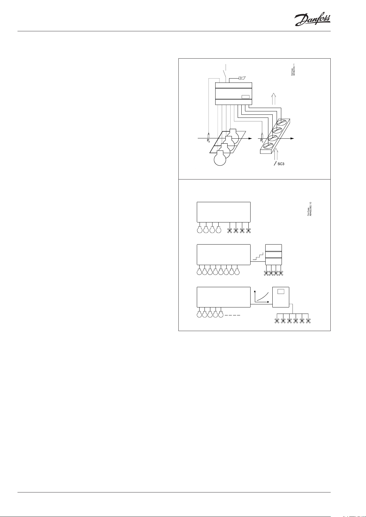
Application
The controller is used for capacity regulation of compressors
and / or condensers in small refrigerating systems.
This controller can regulate up to ten compressors. The condenser
capacity is step regulated via the remaining available digital
outputs and external relay module or variable speed regulated via
a frequency converter.
Advantages
• Patented neutral zone regulation
• Sequential or cyclic operation
• Possibility of suction pressure optimisation via the data
communication
• Load shedding function
Regulation
Regulation is based on signals from one pressure transmitter for
the compressor regulation and one pressure transmitter for the
condenser regulation plus one temperature sensor for the air
temperature before the condenser.
Functions
• Relays for capacity regulation
• Voltage output for capacity regulation
• Status inputs. An interrupted signal indicates that the
safety circuit has been activated and the respective
circuit stopped
• Contact inputs for indication of alarms
• Contact inputs for displacement of references or for
indication of alarms
• Alarm relay
• External start/stop of regulation
• Possibility of data communication
Operation
All operation takes place either via data communication or
via connection of a display type EKA 164. The display can be
disconnected after the installation.
2 Manual RS8HG102 © Danfoss 11-2015 AK-PC 531B
Page 3
Function
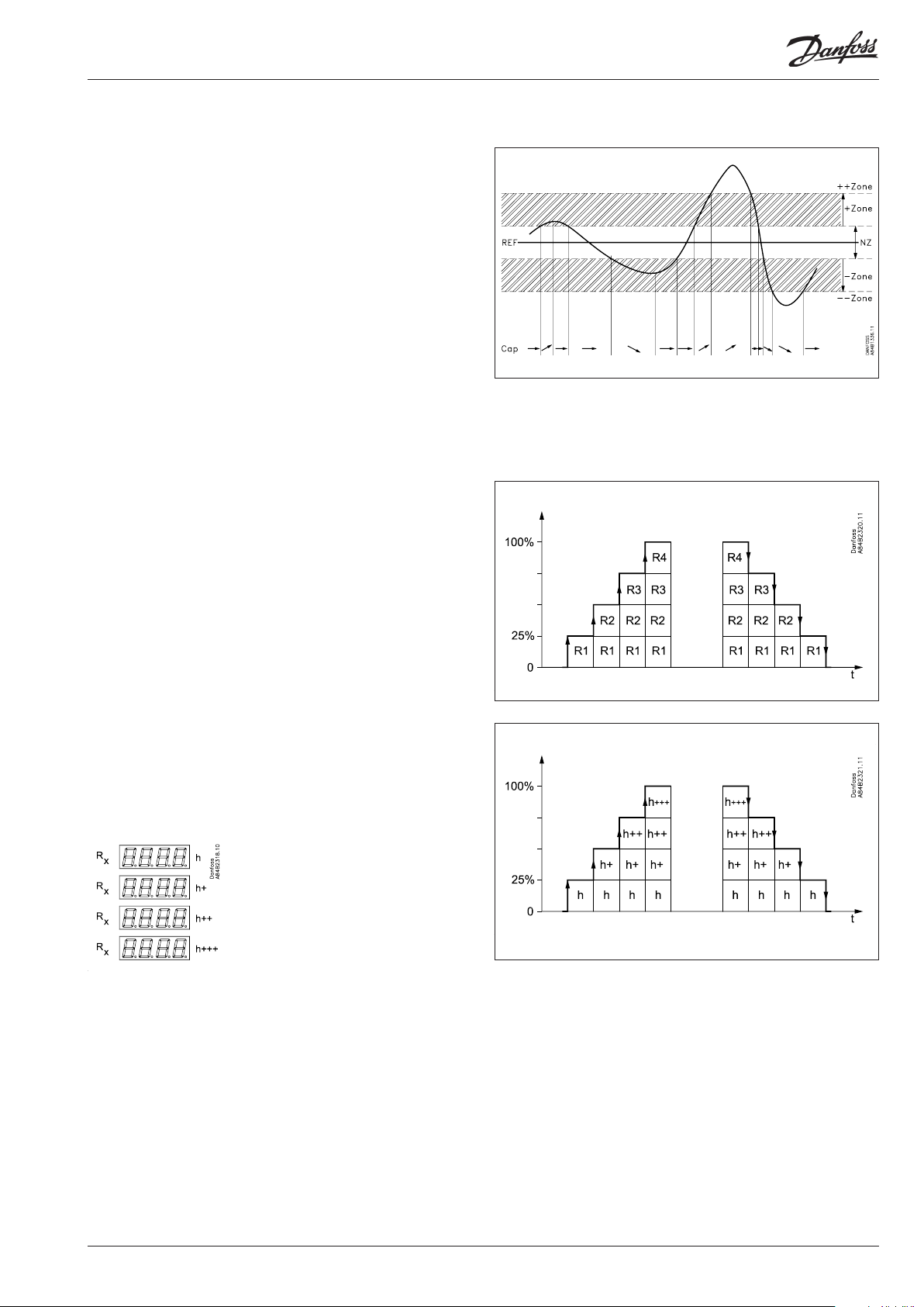
Capacity regulation
The cut-in capacity is controlled by signals from the connected
pressure transmitter and the set reference.
Outside the reference a neutral zone is set where the capacity
will neither be cut in nor out.
Outside the neutral zone (in the hatched areas named +zone
and -zone) the capacity will be cut in or out if the regulation
registers a change of pressure “away” from the neutral zone.
Cut in and cut out will take place with the set time delays.
If the pressure however “approaches” the neutral zone, the
controller will make no changes of the cut-in capacity.
If regulation takes place outside the hatched area (named
++zone and --zone), changes of the cut-in capacity will occur
somewhat faster than if it were in the hatched area.
Cut in of steps can be dened for either sequential or cyclic
operation.
Sequential (rst in - last out)
The relays are here cut in in sequence – rst relay number 1,
then 2, etc.
Cutout takes place in the opposite sequence, i.e. the last
cut-in relay will be cut out rst.
Cyclic (rst in - rst out)
The relays are coupled here so that the operating time of
the individual relays will become equalised.
At each cutin the regulation scans the individual relays’
timer, cutting in the relay with least time on it.
At each cutout a similar thing happens. Here the relay is cut
out that has most hours on the timer.
Rx = random relay
h = number of hours
AK-PC 531B Manual RS8HG102 © Danfoss 11-2015 3
Page 4
Suvey of functions
Function Para-
meter
Normal display
If the two displays are mounted:
P0 will be shown on EKA 165 / EKA 164 (the one with buttons)
Pc will be shown on EKA 163
Compressor regulation reference Compressor control
P0 setpoint
Regulation is based on the set value plus an oset, if applicable. An oset can be
created from night setback r13 and/or from a master gateway’s override function.
Oset
The set reference may be displaced with a xed value when a signal is received at
the DI4 input or from the function "Night setback" (r27).
(Cf. also Denition of DI4 input).
Night setback
OFF: No change of the reference
ON: Oset value forms part of the reference
Reference
The regulation reference is shown here
Set point limitation
With these settings the setpoint can only be set between the two values.
(This also apply if regulation with "P0-optimisation function".)
Max. permissible setpoint value. r25 P0RefMax b
Min. permissible setpoint value. r26 P0RefMin b
Neutral zone
There is a neutral zone around the reference. See also page 3.
Correction of pressure measurement
An oset adjustment of the registered pressure can be made.
Unit
Here you can select whether thedisplay is to indicate pressure in bar or in Psig.
And temperatures in °C or °F.
0: Will give bar and °C.
1: Will give Psig and °F.
Start/stop of refrigeration
With this setting the refrigeration can be started and stopped. Start/stop of
refrigeration may also be performed with an external contact function connected
to the input named “ON input”.
Condenser regulation reference Condenser control
Pc setpoint
Regulation is based on the set value plus an oset, if applicable. An oset can be
created via the “r34” function and/or from a master gateway’s override function.
Oset
The set reference may be displaced with a xed value when a signal is received
at the DI5 input. (Cf. also Denition of DI5 input).
Pc reference variation
1: No change of the reference. Regulation based on set setpoint.
2: Outdoor temperature forms part of the reference. The outdoor temperature
is measured with Sc3. When the outdoor temperature drops one degree, the
reference is lowered one degree.
Setting 1 and 2 operate with a PI regulation.
If the system is unstable and the PI regulation not satisfactory the I element may
be left out, so there will be P regulation only.
3: As 1, but with P regulation
4: As 2, but with P regulation
The regulation reference is shown here. r29 Cond ref. b
The mean temperature dierence across the condenser at maximum load (dim tm K) r35 Dim.Tm K
The mean temperature dierence across the condenser at the lowest relevant compressor capacity (min tm K)
Set point limitation
With these settings the setpoint can only be set between the two values.
Max. permissible setpoint value. r30 PcRefMax b
Min. permissible setpoint value. r31 PcRefMin b
Parameter by operation via
data communication
P0 b (bar)
Pc b (bar)
r23 Set Point b
r13 Night oset
r27 NightSetBack
r24 Comp ref. b
r01 Neutral zone
r04 AdjustSensor
r05 (In AKM only bar or °C is used,
whatever the setting)
r12 Main Switch
r28 Set Point b
r34 Press.oset
r33 Pc mode
r56 Min tm K
4 Manual RS8HG102 © Danfoss 11-2015 AK-PC 531B
Page 5
Correction of pressure measurement
An oset adjustment of the registered pressure can be made.
Compressor capacity Compressor pack cong.
Running time
To prevent frequent start/stop, values have to be set for how the relays are to cut
in and out.
Min. ON time for relays.
(The time is not used if the relay cuts an unloader in or out).
Min. time period between cutin of same relay. c07 MinRecyTime
Setting for neutral zone regulation
Regulation band over the neutral zonen c10 + Zone b
Time delay between step cut-ins in the regulation band over the neutral zone c11 + Zone m
Time delay between step cut-ins in the regulation band over the "+Zone band". c12 + + Zone m
Regulation band under the neutral zone c13 - Zone b
Time delay between step cut-outs in the regulation band under the neutral zone c14 - Zone m
Time delay between step cut-outs in the regulation band under the "-Zone band" c15 - - Zone m
Compressor conguration
Here you set the combination of number of compressors and any unloaders.
1 = One compressor, 2 = two compressors, 3 = three, 4 = four....10 = ten.
See page 9.
Selection of coupling mode (See also the overview page 9)
1. Sequential: First relay 1 cuts in, then relay 2, etc. Cutout takes place in the opposite
sequence. (”First in, last out”).
2. Cyclic: An automatic operating time equalisation is arranged here, so that all steps
with motor connection will have the same operating time
r32 AdjustSensor
c01 Min.ON time
c16 Compr mode
c08 Step mode
Denition of condenser and number of fans
Here you set the number of fan steps with which regulation has to be carried out (but
max. eight).
1-8: All fans are cut in and out with relays. The rst vacant relay number is assigned to
fan 1, the next to number 2, etc. Steps after DO10 must be executed through connection of a relay module type EKC 331 to the analog output. Cf. drawing on page 9.
9: All fans are controlled via the analog output and a frequency converter.
10: Not used
11-18: Total number of fan relays which are to be connected with alternating start-up.
Read temperature at sensor Sc3 u44 Sc3 temp
Read temperature at sensor Sc4 (sensor is only used for monitoring) u45 Sc4 temp
Read temperature at sensor "Saux" u03 Saux temp
Status on DI3 input u87 DI 3 status
Status on DI4 input u88 DI 4 status
Status on DI5 input u89 DI 5 status
Regulation parameters for the condenser regulation
P: Amplication factor Xp (P = 100/Xp)
If the Xp value is increased, the regulation becomes steadier
I: Integration time Tn
If the Tn value is increased, the regulation becomes steadier
Cutin condenser capacity with manual control. See also “n53” n52 FanManCap%
Manual control of condenser capacity (when ON, the value in “n52” will be used) n53 FanManCap
c29 No. of Fans
- - - - Comp. Cap %
Read cut-in compressor capacity
- - - - Cond. Cap %
Read cut-in condenser capacity
n04 Xp b
n05 Tn s
AK-PC 531B Manual RS8HG102 © Danfoss 11-2015 5
Page 6

Alarm Alarm settings
The controller can give alarm in dierent situations. When there is an alarm all the
light-emitting diodes (LED) will ash on the EKA 164, and the alarm relay will cut in.
(The alarm relay may be used for a compressor No. 10, if required).
P0 min.
Here you set when the alarm at too low suction pressure is to enter into eect. The
value is set as an absolute value.
Alarm delay P0 min.
The time delay is set in minuts. At setting = -1 the alarm is cancelled.
Pc max.
Here you set when the alarm at too high condensing pressure is to enter into eect.
The value is set as an absolute value.
Alarm delay Pc max.
The time delay is set in minuts. At setting = -1 the alarm is cancelled.
Alarm delay DI3 (an interrupted input will give alarm).
The time delay is set in seconds. At max. setting the alarm is cancelled.
Alarm limit for high temperature of the “Saux.” sensor
With setting = 0 the alarm has been opted out.
Alarm delay from "Saux"
If the limit value is exceeded, a timer function will commence. The alarm will
not become active until the set time delay has been passed. The time delay is set
in minutes.
Give the top button a brief push to zeroset the alarm and to have the message
shown on the display.
Miscellaneous Miscellaneous
Pressure transmitter’s working range
Depending on the pressure, a pressure transmitter with a given working range is
used. This working range must be set in the controller (e.g.: -1 to 12 bar
The values must be set in bar if display in °C has been selected. And in psig, if °F has
been selected.
P0-Min. value o20 P0MinTrsPres
P0-Max. value o21 P0MaxTrsPres
Pc-Min. value o47 PcMinTrsPres
Pc-Max. value o48 PcMaxTrsPres
Function for relay output DO9: (Only if C16 < 9)
0. Start / stop of speed regulation
1. Inject on signal for evaporator control
2. Boost ready (at least one compressor is on)
3. Start /stop of condenser fan
Function for relay output DO10: (Only if C16 < 10)
0. Alarm relay
1. Start / stop of speed regulation
2. Inject on signal for evaporator control
3. Boost ready (at least one compressor is on)
4. Start /stop of condenser fan
Function for DI3:
0: Not used
1: Fan safety
2: Alarm input (A30 alarm)
Use of DI4 input
The digital input can be connected to a contact function, and the contact can now
be used for one of the following functions:
Setting / function:
0: DI input not used
1: Regulation reference P0 displaced when contact is cut in
2: Alarm function when the contact cuts out. Alarm “A31” is given when the time
delay has elapsed.
A11 Min. P0. b
A44 Po.AlrmDelay
A30 Max. Pc. b
A45 Pc.AlrmDelay
A29 DI3AlrmDelay
A32 Saux
A03 Alarm delay
Reset alarm
The function zerosets all alarms
when set in pos. ON.
With data communication the
importance of the individual alarms
can be dened. Setting is carried out
in the “Alarm destinations” menu.
See also page 8.
If the values are to be set from the
AKM programme, they must be set in
bar.
o75 DO9 function
o76 DO10 function
o80 DI 3 control
o22 DI4 control
6 Manual RS8HG102 © Danfoss 11-2015 AK-PC 531B
Page 7

Use of DI5 input
The digital input can be connected to a contact function, and the contact can now
be used for one of the following functions:
Setting / function:
0: DI input not used
1: Regulation reference Pc displaced when contact is cut in
2: Alarm function when the contact cuts out. Alarm “A32” is given when the time
delay has elapsed.
Operating hours
The operating hours for the compressor relays can be read in the following menus.
The read value is multiplied by 1000 to obtain the number of hours (f.ex. shows 2.1
for 2100 hours). On reaching 99.9 hours the counter stops and must now be reset to,
say, 0. There will be no alarm or error message for counter overow.
Value for relay number 1 o23 DO1 run hour
Value for relay number 2 o24 DO2 run hour
Value for relay number 3 o25 DO3 run hour
Value for relay number 4 o26 DO4 run hour
Value for relay number 5 o50 DO5 run hour
Value for relay number 6 o51 DO6 run hour
Value for relay number 7 o52 DO7 run hour
Value for relay number 8 o53 DO8 run hour
Value for relay number 9 o53 DO9 run hour
Value for relay number 10 o55 DO10 run hour
Refrigerant setting
Before refrigeration is started, the refrigeration must be dened. You may choose
between the following refrigerants:
1 = R12. 2 = R22. 3 = R134a. 4 = R502. 5 = R717. 6 = R13. 7 = R13b1. 8 = R23.
9 = R500. 10 = R503. 11 = R114. 12 = R142b. 13 = User dened. 14 = R32. 15 = R227.
16 = R401A. 17 = R507. 18 = R402A. 19 = R404A. 20 = R407C. 21 = R407A.
22 = R407B. 23 = R410A. 24 = R170. 25 = R290. 26 = R600. 27 = R600a. 28 = R744.
29 = R1270. 30 = R417A. 31 = R422A. 32 = R413A. 33 = R422D. 34 = R427A.
35 = R438A. 36 = R513A. 37 = R407F.
Warning: Wrong selection of refrigerant may cause damage to the compressor.
Manual control (stopped regulation only)
From this menu the relays can be cut in and out manually. 0 gives no override,
but a number between 1 and 10 will cut in a belonging relay. 1 will cut in relay number 1, 2 relay 2, etc.
11-18 will produce voltage on the analog output. In this way the relays on the
external relay module can be activated. Setting 11 will give a voltage of 1.25 V,
setting 12 will give 2.5 V, etc.
Frequency
Set the net frequency.
Display connection
O: EKA 164
On: EKA 165 (extended display with light-emitting diodes)
Address
If the controller is built into a network with data communication, it must have an
address, and the master gateway of the data communication must then know this
address.
These settings can only be made when a data communication module has been
mounted in the controller and the installation of the data communication cable has
been completed.
This installation is mentioned in a separate document “RC.8A.C”.
The address is set between 1 and 60 o03
The address is sent to the gateway when the menu is set in pos. O o04
Access code
If the settings in the controller are to be protected by a numerical code, you can set a
numerical value between 0 and 100. If not, you can cancel the function with setting
OFF.
o37 Di5 control
(In the AKM display the hour
number has not been multiplied)
o30 Refrigerant
o18 - - -
o12 50 / 60 Hz
(50 = 0, 60 = 1)
o82 - - -
Following installation of a data
communication module, the
controller can be operated on a par
with the other controllers in
ADAP-KOOL® refrigeration controls.
o05
AK-PC 531B Manual RS8HG102 © Danfoss 11-2015 7
Page 8

Operating status
The controller goes through some regulating situations where it is just waiting for the
next point of the regulation. To make these “why is nothing happening” situations visi-
EKC state
(0 = regulation)
ble, you can see an operating status on the display. Push briey (1s) the upper button.
If there is a status code, it will be shown on the display. The individual status codes
have the following meanings
S2: When the relay is operated, it must be activated for min. x minutes (cf. c01) 2
S5: Renewed cutin of the same relay must not take place more often than every x
5
minutes (cf. c07)
S8: The next relay must not cut in until x minutes have elapsed (cf.c11-c12) 8
S9: The next relay must not cut out until x minutes have elapsed (cf. c14-c15) 9
S10: Regulation stopped with the internal og external start/stop 10
S25: Manuel control of outputs via function "o18" 25
S34: Safety cutout. Setting A30 is exceeded or all safety inputs (29-36) are open 34
S47: Controller is in "Load shed mode" 47
PS: Access code is required before you have access to the settings
Alarm messages Alarms "Destinations"
A2: Low P0 - - - Low P0 alarm
A11: No refrigerant has been selected (cf. o30) - - - No RFG Sel
A17: High Pc - - - Hi Pc alarm
A19 - 26: Compressor fault. Interrupted signal on input "Comp 1" /2/3/4/5/6/7/8 - - - Comp._ fault
A27: High temperature alarm for sensor "Housing" - - - Housing temp
A28: External alarm. Interrupted signal on input "DI1" Comp 9 fault
A29: External alarm. Interrupted signal on input "DI2" Comp 10 fault
A30: External alarm. Interrupted signal on input "DI3" DI3 alarm
A31: External alarm. Interrupted signal on input "DI4" DI4 alarm
A32: External alarm. Interrupted signal on input "DI5" DI5 alarm
A34: Fan failure. Interrupted signal on input "Fan 1" ("DI3") - - - Fan _ fault
A45: Regulation stopped with setting or with external switch A45 Stand by
E1: Error in the controller Ctrl. fault
E2: Control signal outside the range (short-circuited/interrupted) Out of range
Conguration settings (compressor and fan denitions, coupling mode and refrigerant) can only take place when regulation is stopped.
8 Manual RS8HG102 © Danfoss 11-2015 AK-PC 531B
Page 9

Compressor conguration
Setting "c16" will dene the conguration.
Setting "c08" will dene coupling mode.
Capacity step
All capacity steps are presumed to be
identical.
Coupling mode
Coupling mode 1 = sequential operation.
Coupling mode 2 = cyclic operation.
Condenser couplings
When the compressor relays have been established the turn
comes to the fan relays.
The rst vacant relay (DO1-DO10) will become the rst fan
relay. It will be followed by the subsequent relays. If more relays
are required than the vacant DO relays, a relay module can be
connected to the analog output. The function is, as follows:
If there are up to four external fans on an EKC 331:
In EKC 331 the voltage range must be set to 0-5 V (“o10” = 6).
In EKC 331 the number of steps must be set to 4 (“o19” = 4)
(also when fewer fans are connected).
If there are more than four external fans on two EKC 331 units:
1.
2.
Alternating start-up of fans:
(only if c29 is 11 to 18)
The fans can be dened to start alternately when they have all
been stopped.
The rst time regulation is started, fan 1 will be started rst – the
regulation determines whether additional fans will be started.
After the next time all fans are stopped, fan 2 will be the rst to be
started, and so on.
Fan 1 will again be the rst fan to be started when the rotation has
been through the total number of fans.
If there is more than one fan on an EKC 331, it will not be possible
to start the other fans rst. Here, the fan with the lowest voltage
step will always be the one which is started rst.
If the entire condenser capacity is to be controlled by a frequency
converter:
AK-PC 531B must send an analog signal about the required
capacity (“c29” = 9).
The signal varies from 0 to 10 V. Signal and capacity have the
following context.
In the rst EKC 331, set 0-5 V (“o10” = 6).
In the second EKC 331, set 5-10 V (“o10” = 7).
In both EKC’s the number of steps must be set to 4 (“o19” = 4)
(also when fewer fans are connected to the second EKC).
AK-PC 531B Manual RS8HG102 © Danfoss 11-2015 9
Page 10

Operation
Data communication
If the controller is extended with data communication, the operation can be performed from a system unit.
The importance of the alarms that are sent can be dened with
the setting: 1 (High), 2 (Medium), 3 (Low) or 0 (No alarm).
Operation via external display
The values will be shown with three digits, and with a setting you
can determine whether the pressures are to be shown in SI units
(°C / bar) or US units (°F / psig.).
There are three options for the display.
EKA 165
To operate the controller and view the evaporation pressure.
If the lowermost key is pressed, the condensation pressure will
be shown briey in the display. (If regulation is based only on the
condensation pressure, the display will always show Pc).
During normal operation the light-emitting diodes in the display
will indicate where regulation is taking place.
Highest + second highest : ++Zone
Second highest : +Zone
"None" : Neutral zone
Second lowest : -Zone
Lowest+ second lowest : - - Zone
EKA 165
EKA 163
EKA 164
The buttons on the display
When you want to change a setting, the upper and the lower
buttons will give you a higher or lower value depending on the
button you are pushing. But before you change the value, you
must have access to the menu. You obtain this by pushing the
upper button for a couple of seconds - you will then enter the
column with parameter codes. Find the parameter code you want
to change and push the middle button. When you have changed
the value, save the new value by once more pushing the middle
button.
The other LEDs on the display will show the functions that are
active:
• Relays for compressors
• Relays for fans
• Input signals for the digital inputs
• The optimisation LED will light up when the reference is 2 K or
more over the set point.
EKA 163
If the condensation pressure is to be shown constantly, a display
without operating keys can be connected.
EKA 164
To operate the controller and view the evaporation pressure.
If the lowermost key is pressed, the condensation pressure will be
shown briey in the display.
Like the EKA 165, the LEDs in the display will show where the
regulation is located.
Or short:
1. Push the upper button (long push) until a parameter is shown
2. Push one of the buttons and nd the parameter you want to
change
3. Push the middle button until the setting value is shown
4. Push one of the buttons and select the new value
5. Push the middle button again to conclude the setting
( A brief pushing will show the active alarm codes.)
10 Manual RS8HG102 © Danfoss 11-2015 AK-PC 531B
Page 11

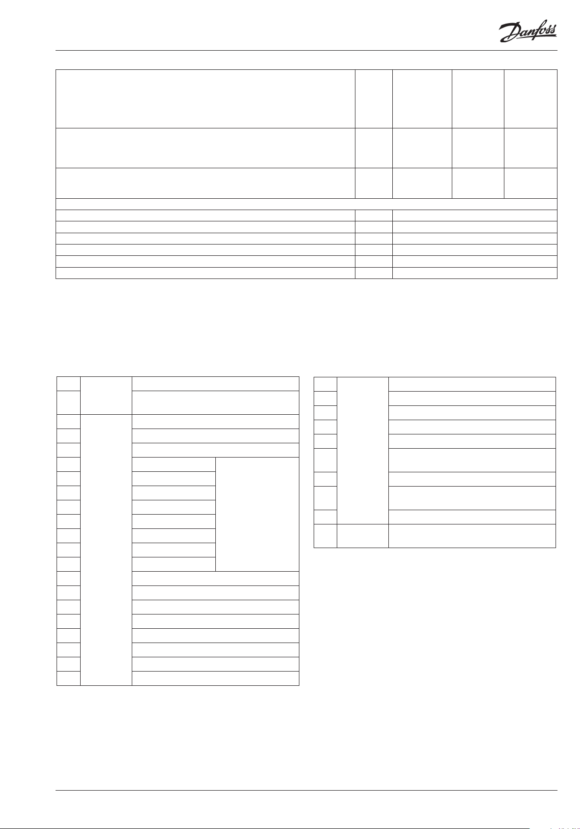
Menu survey
Sequence
1. Quick- start
To get the system up and running quickly so that cooling can be commenced, start it by setting the following parameters (these parameters can only be set when the regulation is stopped r12=0):
r23, r28 and then either (c08 and c16) – continue with c29, o30, o75, o76, o80 and nally r12=1.
2. Once the regulation is under way, you can go through the other parameters and adjust them in situ.
Function
Normal display
Shows P0 in EKA 165 (display with buttons) - bar
Shows Pc in EKA 163 - bar
P0 reference
Neutral zone r01 0.1 bar 5.0 bar 0.4 bar
Correction of signal from P0 sensor
Select view; SI or US. 0=SI (bar /°C), 1=US (Psig /°F) r05 0 1 0
Start/Stop of regulation r12 OFF ON OFF
Reference oset for P0 (see also r27) r13 -5.0 bar 5.0 bar 0.0 bar
Set regulation setpoint for P0 r23 -1 bar 60.0 bar 3.5 bar
Shows total P0 reference
( r23 + various displacements)
Limitation: P0 reference max. value
(also applies to regulation with reference displacement)
Limitation: P0 referencen min. value
(also applies to regulation with reference displacement)
Displacement of P0 (ON=active “r13”) r27 OFF ON OFF
Pc reference
Set regulation setpoint for Pc r28 0.0 bar 110.0 bar 15.0 bar
Shows total Pc reference r29 bar
Limitation: Pc referencen max. value r30 -0.0 bar 130.0 bar 60.0 bar
Limitation: Pc referencen min. value r31 0.0 bar 60.0 bar 0.0 bar
Correction of signal from Pc sensor r32 -5.0 bar 5.0 bar 0.0 bar
Pc reference variation.1 and 2 are PI-regulation
1: Fixed reference. “r28” is used
2: Variable reference. Outdoor temperature (Sc3) included in the reference
3: As 1, but with P-regulation (Xp-band)
4: As 2, but with P-regulation (Xp-band)
Reference oset for Pc r34 -5.0 bar 5.0 bar 0.0 bar
The mean temperature dierence across the condenser at maximum load (dim tm K) r35 3.0 50.0 10.0
The mean temperature dierence across the condenser at the lowest relevant compressor
capacity (min tm K)
Capacity
Min. ON time for compressor relays c01 0 min 30 min. 0
Min. time period between cutins of same compressor relay c07 0 min. 60 min 4
Denition of regulation mode
1: Sequential (step mode / FILO)
2: Cyclic (step mode / FIFO)
Regulation parameter for + Zone c10 0.1 bar 2.0 bar 0.4 bar
Regulation parameter for + Zone c11 0.1 min 60 min 4.0
Regulation parameter for ++ Zone c12 0.1 min. 20 min 2.0
Regulation parameter for - Zone c13 0.1 bar 2.0 bar 0.3 bar
Regulation parameter for - Zone c14 0.1 min. 60 min 1.0
Regulation parameter for - - Zone c15 0.02 min. 20 min 0.5
Denition of compressor connections.
See options on page 3.
Denition of condenser:
1-8: Total number of fan relays or voltage step on the voltage output
9: Only via analog output and start of frequency converter
10: Not used
11- 18: Total number of fan relays which are to be connected with alternating start-up.
Parameter
r04 -5.0 bar 5.0 bar 0.0 bar
r24 bar
r25 -1.0 bar 60.0 bar 40.0 bar
r26 -1.0 bar 40.0 bar -1.0 bar
r33 1 4 1
r56 3.0 50.0 8.0
c08 1 2 1
c16 1 10 0
c29 0/OFF 18 0
Min. Max. Factory
setting
To be continued
SW: 1.0x
AK-PC 531B Manual RS8HG102 © Danfoss 11-2015 11
Page 12

Cut in compressor capacity with manual control. See also “c32” c31 0% 100% 0
Manual control of compressor capacity (when ON, the value in “c31” will be used) c32 OFF ON OFF
Set capacity for Load shed period c35 0% 100% 25%
Po limit to stop Load shed c36 0.0 bar 60.0 bar 60.0 bar
Max period for Load shed On c37 5 min. 60 min. 30 min.
Control Load shed on/o c91 0/OFF 1/ON 0/OFF
Proportinal band Xp for (P= 100/Xp) condenser regulation n04 0.2 bar 10.0 bar 3.0 bar
I: Integration time Tn for condenser regulation n05 30 s 600 s 150
Cutin condenser capacity with manual control. See also “n53” n52 0% 100% 0
Manual control of condenser capacity (when ON, the value in “n52” will be used) n53 OFF ON OFF
Start speed The voltage for the speed regulation is kept at 0V until the regulation requires
a higher value than the value set here.
Min. speed. The voltage for the speed regulation switches to 0V when the regulation
requires a lower value than the value set here.
n54 0% 75% 20%
n55 0% 50% 10%
Alarm
Delay time for a A32 alarm A03 0 min. 90 min. 0 min.
Low alarm and safety limit for P0 A11 -1.0 bar 40 bar 0.5 bar
Delay time for a DI3 alarm A29 0 min. (-1=OFF) 999 min. OFF
Upper alarm and safety limit for Pc A30 0.0 bar 200 bar 60.0 bar
Upper alarm limit for sensor "Saux1" A32 1°C (0=OFF) 140°C OFF
Delay time for a P0 alarm A44 0 min. (-1=OFF) 999 min. 0 min.
Delay time for a Pc alarm A45 0 min. (-1=OFF) 999 min. 0 min.
Miscellaneous
Controllers address o03* 1 990
On/o switch (service-pin message) o04* - -
Access code o05 1 (0=OFF) 100 OFF
Set supply voltage frequency o12 50 Hz 60 H 0
Manual control of outputs:
0: No override
1-10: 1 will cut in relay 1, 2 relay 2, etc.
o18 0 18 0
11-18: Gives voltage signal on the analog output. (11 gives 1.25 V, and so on in steps of
1.25 V
P0 pressure transmitter’s working range - min. value o20 -1 bar 0 bar -1.0
P0 pressure transmitter’s working range - max. value o21 1 bar 200 bar 12.0
Use of DI4-input
0=not used. 1=P0 displacement. 2=alarm function. Alarm="A31"
o22 0 2 0
Operating hours of relay 1 (value time 1000) o23 0.0 h 99.9 h 0.0
Operating hours of relay 2 (value time 1000) o24 0.0 h 99.9 h 0.0
Operating hours of relay 3 (value time 1000 o25 0.0 h 99.9 h 0.0
Operating hours of relay 4 (value time 1000) o26 0.0 h 99.9 h 0.0
Setting of refrigerant
1=R12. 2=R22. 3=R134a. 4=R502. 5=R717. 6=R13. 7=R13b1. 8=R23. 9=R500. 10=R503.
11=R114. 12=R142b. 13=User dened. 14=R32. 15=R227. 16=R401A. 17=R507.
18=R402A. 19=R404A. 20=R407C. 21=R407A. 22=R407B. 23=R410A. 24=R170.
o30 0 37 0
25=R290. 26=R600. 27=R600a. 28=R744. 29=R1270. 30=R417A. 31=R422A. 32=R413A.
33=R422D. 34=R427A. 35=R438A. 36=R513A. 37=R407F
Use of DI5-input
0=not used. 1=Pc displacment. 2=alarm function. Alarm="A32"
o37 0 2 0
Pc pressure transmitter’s working range - min. value o47 -1 bar 0 bar -1.0
Pc pressure transmitter’s working range - max. value o48 1 bar 200 bar 34.0
Operating hours of relay 5 (value time 1000) o50 0.0 h 99.9 h 0.0
Operating hours of relay 6 (value time 1000) o51 0.0 h 99.9 h 0.0
Operating hours of relay 7 (value time 1000) o52 0.0 h 99.9 h 0.0
Operating hours of relay 8 (value time 1000) o53 0.0 h 99.9 h 0.0
Operating hours of relay 9 (value time 1000) o54 0.0 h 99.9 h 0.0
Operating hours of relay 10 (value time 1000) o55 0.0 h 99.9 h 0.0
Function for relay output DO9: (Only if C16 < 9)
0. Start / stop of speed regulation
1. Inject on signal for evaporator control
o75 0 3 0
2. Boost ready (at least one compressor is on)
3. Start /stop of condenser fan
* this setting is only possible if data communication module is mounted in the controller
To be continued
12 Manual RS8HG102 © Danfoss 11-2015 AK-PC 531B
Page 13
Function for relay output DO10: (Only if C16 < 10)
0. Alarm relay
1. Start / stop of speed regulation
2. Inject on signal for evaporator control
3. Boost ready (at least one compressor is on)
4. Start /stop of condenser fan
Function for DI3:
0: Not used
1: Fan safety
2: Alarm input (A30 alarm)
Display connection
O: EKA 164
On: EKA 165 (extended display with light-emitting diodes)
Service
Read temperature at sensor "Saux" u03 °C
Read temperature at sensor "Sc3" u44 °C
Read temperature at sensor "Sc4" u45 °C
Status on DI3 input u87
Status on DI4 input u88
Status on DI5 input u89
o76 0 4 0
o80 0 2 0
o82 O On O
The controller can give the following messages
E1 Error
message
E2 Regulation is outside the range, or the control
A2 Alarm
message
A11 Refrigerant not selected
A17 High Pc
A19 Compressor 1 error
A20 Compressor 2 error
A21 Compressor 3 error
A22 Compressor 4 error
A23 Compressor 5 error
A24
A25 Compressor 7 error
A26 Compressor 8 error
A27 Room temperature alarm (Saux1 temp.)
A28 DI 1 alarm. Compressor 9 error
A29 DI 2 alarm. Compressor 10 error
A30 DI 3 alarm. Terminal 49 interrupted
A31 DI 4 alarm. Terminal 50 interrupted
A32 DI 5 alarm. Terminal 52 interrupted
A34 Fan alarm. There is no signal on DI1 input
A45 Regulation stopped
Fault in controller
signal is defective *
Low P0
Compressor 6 error
The actual compressors
safety circuit is
interrupted.
That is to say the signal
is missing on one of the
terminals 29-36
S0 Status
message
S2 Wait for “c01”
S5 Wait for “c07”
S8 Wait for “c11” or “c12”
S9 Wait for “c14” or “c15”
S10 Refrigeration stopped by the internal or external
S25 Manual control of outputs
S34 Safety cutout. Setting A30 is exceeded or all
S47 Controller is in "Load shed mode"
PS Info Access code is required before you have access to
Regulation
start/stop function
safety inputs (29-36) are open
the settings
Messages can be brought up on the display by briey pressing
the uppermost key. If there is more than one alarm, they can be
scrolled through
Factory setting
If you need to return to the factory-set values, it can be done in
this way:
- Cut out the supply voltage to the controller
- Keep upper and lower button depressed at the same time as you
recon nect the supply voltage
AK-PC 531B Manual RS8HG102 © Danfoss 11-2015 13
Page 14

Override
The controller contains a number of functions that can be used
together with the override function in the master gateway.
They can therefore only be used in combination with data
communication.
Function via data communication Functions to be used in the gateway’s
Stop of injection when the compressor is
stopped
Night serback Day/night control and time schedule r27 NightSetback
Suction pressure optimisation P0 optimisation
AK-PC 531B registers the refrigeration point which handles the largest capacity (requires
the lowest suction pressure). The parameter may be logged for use in a service situation.
override function
AKC ON - - - MC Inject ON
Selection of parameter in AK-PC 531B
084B8014 Sw.1.0x
Select controller address (The parameters
are found automatically and
do not become visible).
- - - MLC
Safety function
Monitoring of maximum discharge pressure
The function cuts in all condenser steps and gradually cuts out compressor steps, if the condensing pressure exceeds the
permitted value. The cutout limit is the setting in "A30".
The function starts at a value that is 3 K below the set value. At this point the entire condenser capacity is cut in at the same
time as 33% of the compressor capacity is cut out. (however min. one step). This is repeated for each 30-second interval.
The alarm function is activated.
If the temperature (pressure) rises to the set limit value, the following happens:
- all compressor steps are immediately cut out
- the condenser capacity remains cut in
The alarm ceases when the temperature (pressure) has dropped to the 3 K below the limit value for 60 seconds.
Renewed cut in of compressor steps is allowed when the temperature (pressure) has dropped to the 3 K below the limit value.
Restart of the compressor is dependent on expiry of the restart timer.
Monitoring of minimum suction pressure
The function immediately cuts out all compressor steps if the suction pressure becomes lower than the permitted value.
The cut out limit is the setting in "A11".
Cut outs activate the alarm function.
The alarm ceases when the pressure (temperature) is above the cut out limit.
Renewed cut in of compressor steps is allowed when the alarm has stopped (the time delay has expired).
Emergency procedure
If the controller registers irregularities in the registered signals, it will start an emergency procedure:
For compressor regulation:
- If the signal from the pressure transmitter becomes smaller than expected, the controller will continue operating with the
average capacity that has been cut in during the past 60 minutes. This cut-in capacity will gradually decline as time passes.
- If the signal for the suction pressure becomes smaller than the set value of A11, the capacity will instantly be cut out.
For condenser regulation:
- If the signal from the pressure transmitter becomes smaller than expected, or if the condensing pressure becomes bigger
than the set value of A30, the entire capacity will in stantly be cut in.
14 Manual RS8HG102 © Danfoss 11-2015 AK-PC 531B
Page 15

Connections
All inputs are low voltage
All relay outputs may be
high voltage
Necessary connections
Terminals:
1-2 Supply voltage 24 V a.c.
4- 19 Relay outputs for either compressors, unloaders or fan
motors
27-28 24 V signal to start / stop of regulation
27-29 24 V signal from the safety circuit DO 1
27-30 24 V signal from the safety circuit DO 2
27-31 24 V signal from the safety circuit DO 3
27-32 24 V signal from the safety circuit DO 4
27-33 24 V signal from the safety circuit DO 5
27-34 24 V signal from the safety circuit DO 6
27-35 24 V signal from the safety circuit DO 7
27-36 24 V signal from the safety circuit DO 8
57-59 Suction pressure. Voltage signal from AKS 32R **
60-62 Condenser pressure. Voltage signal from AKS 32R **
Application dependent connections
20-21 Compressor 9, if applicable
Or any safety function.
22-23 Compressor 10, if applicable
Or alarm relay on 22-24, if there is one
There is connection between 22 and 24 in alarm
situations and when the controller is de-energised
37-38 Voltage signal to external condenser control
(see settings page 4)
39-41 Possibility of connecting an external display type EKA 163
for display of Pc
42-44 Possibility of connecting an external display type EKA 163
for display of P0, or EKA 165 for operation and display of
P0
45-46 DI1 - Compressor 9 safety circuit (On = OK)
45-47 DI2 - Compressor 10 safety circuit (On = OK)
48-49 DI3 - Contact function for alarm signal
48-50 DI4 - Contact function for displacement of the suction
pressure reference or for alarm signal.
51-52 DI5 - Contact function for displacement of the condenser
pressure reference or for alarm signal.
51-53 Separate sensor Saux1. Sensor signal from AKS 11/ AKS 12
54-55 Out temperature Sc3. Sensor signal from AKS 11/ AKS 12
54-56 Separate sensor Sc4. Sensor signal from AKS 11/ AKS 12
Data communication
25-26 Mount only, if a data communication module has been
tted.
For ethernet communication the plug connection RJ45
must be used.
It is important that the installation of the data communi-
cation cable be done correctly. Cf. separate literature No.
RC8AC.
AK-PC 531B Manual RS8HG102 © Danfoss 11-2015 15
Page 16

Data Ordering
Danfoss
84B2330.11
Supply voltage 24 V a.c. +/-15% 50/60 Hz, 5 VA
2 pcs. Pressure transmitters type AKS 32R
Input signal
3 pcs. temperature sensor input for PT 1000
ohm/0°C or PTC 1000 ohm/25°C
1 pcs. for Start/stop of regulation
Digitale input from
contact function.
8 pcs. for monitoring of safety circuits
3 pcs. for alarm function
2 pcs. for alarm function or for displacement
of references
Relay output for
capacity regulation
Relay output for
capacity regulation or
8 pcs. SPST
1 pcs. SPST
AC-1: 3 A (ohmic)
AC-15: 2 A (inductive)
other function
Alarm relay or
Relay output for
capacity regulation or
1 pcs. SPDT
AC-1: 6 A (ohmic)
AC-15: 3 A (inductive)
other function
Voltage output 0-10 V d.c.
EKA 163 Pc display
Display outputs
Data communication
EKA 164 or EKA 165
Possible to connect a data communication
module
Operation and P0
display
0 - 55°C, during operation
Environments
-40 - 70°C, during transport
20 - 80% Rh, not condensing
No shock inuence / vibrations
Enclosure IP 20
Weight 0.4 kg
Mounting DIN rail or on wall
Terminals max. 2.5 mm2 multicore
EU Low voltage Directive and EMC demands
Approvals
re CE-marking complied with.
LVD-tested acc. to EN 60730-1 and EN 60730-2-9
EMC-tested acc. to EN61000-6-2 and 3
Type Function Code no.
AK-PC 531B Capacity controller 084B8014
EKA 163B Display unit 084B8574
EKA 164B Display unit with operation buttons 084B8575
EKA 165
EKA 175 Data communication module, RS 485 084B7093
EKA 177 Data communication module, Ethernet 084B8031
Dimensions
AK-PC 531B
Display unit with operation buttons and
LEDs
084B8573
Cable for display unit 2 m, 1 pcs. 084B7298
Cable for display unit 6 m, 1 pcs. 084B7299
Pressure transmitter / temperature sensor
Please refer to catalogue RK.0Y.G...
Only for front mounting (IP 40)
Only connection via plugs
Display type EKA 163 / EKA 164
Installation considerations
Accidental damage, poor installation, or site conditions, can
give rise to malfunctions of the control system, and ultimately lead to a
plant breakdown.
Every possible safeguard is incorporated into our products to prevent this.
However, a wrong installation, for example, could still present problems.
Electronic controls are no substitute for normal, good engineering practice.
Danfoss wil not be responsible for any goods, or plant
components, damaged as a result of the above defects.
It is the installer's responsibility to check the installation
thoroughly, and to t the necessary safety devices.
Special reference is made to the necessity of signals to the controller when
the compressor is stopped and to the need
of liquid receivers before the compressors.
Your local Danfoss agent will be pleased to assist with further advice, etc.
Danfoss can accept no responsibility for possible errors in catalogues, brochures and other printed material. Danfoss reserves the right to alter its products without notice. This also applies to products
already on order provided that such alternations can be made without subsequential changes being necessary in specications already agreed.
All trademarks in this material are property of the respecitve companies. Danfoss and Danfoss logotype are trademarks of Danfoss A/S. All rights reserved.
Display type EKA 165
16 Manual RS8HG102 © Danfoss 11-2015 AK-PC 531B
ADAP-KOOL®
 Loading...