

Page 1

User Guide
Capacity controller for dry cooler
AK-PC 420
ADAP-KOOL® Refrigeration control systems
Page 2
Introduction
Application
The controller is used for capacity regulation of a dry cooler
including fans, three-way valve and pumps.
Advantages
• Complete dry cooler control
• Several combination options for sensor selection
• Heat recovery acc. to external voltage signal.
Regulation
Capacity regulation can include fans combined with a three-way
valve or just fans. The following sensor signals can be used in
regulation:
• Condensing pressure Pc
• Brine temperature S7, located immediately after the three-way
valve outlet
• Brine temperature S8, located by the outlet from the dry cooler
• Outdoor temperature sensor Sc3, located by the air inlet to the
dry cooler.
• Either S7, Pc or S8 can be used as a regulation sensor.
Functions
• Three-way valve control
• Speed regulation or step-by-step coupling of up to six fans
• Safety monitoring of fans
• Overriding of reference acc. to external voltage signal or outdoor
temperature
• Separate reference for heat recovery
• Control and monitoring of twin pumps
• Monitoring of ow switch
• Contact inputs to alarms
• External start/stop of regulation
• Data communication via extra module
Operation
All operation takes place either via data communication or via
connection of a display type EKA 164 .
Contents
Introduction ....................................................................................................... 2
Function ............................................................................................................... 3
Survey of functions .......................................................................................... 8
Operation .......................................................................................................... 13
Menu survey .....................................................................................................14
Connections ..................................................................................................... 16
Data ..................................................................................................................... 17
Ordering ............................................................................................................17
Montage ............................................................................................................ 17
Appendix - Reference and regulation .....................................................18
2 Manual RS8EL402 © Danfoss 03-2010 AK-PC 420
Page 3
Function
Application
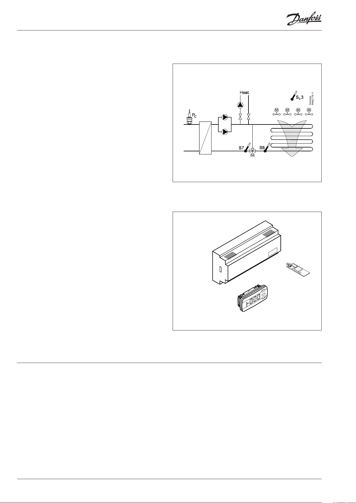
Regulation sensor and system type are selected via one single setting. The setting will dene both the regulation sensor, if a threeway valve is being used, and how the fans are to be controlled.
The fans are controlled either in steps or together with a speed
control. If steps are used, up to six fans can be controlled.
Application 1-4
The capacity here is controlled via the fans combined with a threeway valve.
Applications 1 and 2 use brine return temperature S7 at the
three-way valve outlet as regulation sensor and the fan capacity is
controlled either in steps or via speed control.
The S8 sensor, which is tted to the dry cooler’s outlet should be
used in the control if there is a large distance between the dry
cooler and the three-way valve. Use of the S8 sensor will provide
more robust regulation, which takes long pipe lengths into account. The S8 sensor must be tted close to the dry cooler’s outlet.
Regulation
(o61)
1 S7 S8 (P + PI) x Step
2 S7 S8 (P + PI) x Speed
3 Pc S7 / S7+S8 (PI) x Step
4 Pc S7 / S7+S8 (PI) x Speed
5 S8 Step
6 S8 Speed
Regulation
sensor
Optional
sensor
3-way
valve
Fan
control
Applications 3 and 4 use brine condensation pressure Pc as regulation sensor and the fan capacity is controlled either in steps or via
speed control.
For PI control the use of the S7 and S8 sensors is optional but they
should be tted if there is a large distance between the dry cooler
and the three-way valve. Use of the sensors will provide more
robust regulation, which takes long pipe lengths into account. The
S8 sensor must be tted close to the dry cooler’s outlet.
For P control the S7 and S8 sensors are not used in the regulation,
but they can be tted to ensure that the emergency control functions in the even of the Pc signal failing.
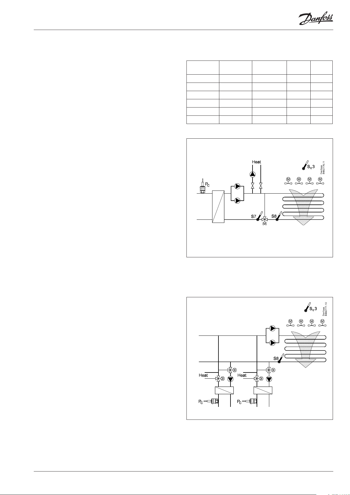
Applications 5-6
Here the capacity is controlled via step-by-step coupling or speed
control on the basis of the dry cooler’s discharge temperature S8.
This application is used in particular when another controller takes
care of the regulation of the three-way valve, e.g. to cool several
parallel-coupled condensers.
NB.
The sensors Pc and S7 must not be located in positions other than
those specied, as they are used for emergency regulation if the
primary regulation sensor develops a fault.
The S8 sensor can be located in a dierent position than the one
indicated if it is not used in the control.
If the S8 sensor is required in the control, the setting "o96, S8
optional" must be selected as ON.
If the S8 sensor is not used in the regulation, it can be located
anywhere.
AK-PC 420 Manual RS8EL402 © Danfoss 03-2010 3
Page 4
Capacity regulation
Three-way valve + step-by-step coupling of fans (applications 1 and 3)
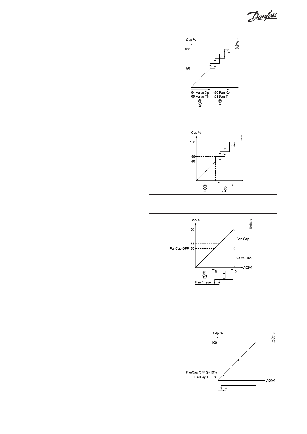
Capacity regulation takes place via a P or PI regulation, which controls the three-way valve and subsequent step-by-step coupling of
the fans.
First of all regulation takes place on the three-way valve via the analogue output. The output can be set at 0-10 V or 10-0 V, depending on which valve function is desired. Only when the three-way
valve is fully open do the fans start up.
The capacity of the three-way valve is 50% of the total capacity.
The P/PI controller has separate regulation settings (proportional
band and integration time) for the three-way valve and the fans
respectively.
Capacity overlap – start of fans
As mentioned above, the three-way valve comprises a xed 50% of
the total capacity. In some systems it may be necessary to start the
fans slightly before (or slightly after) the three-way valve has been
fully opened. An overlap is created here between the three-way
valve and the start of the fans. This is done by changing the setting
“FanCap OFF%” from 50% to, for example, 40% (the setting denes
the capacity at which the last fan stops). In this case the fans are
started before the three-way valve is fully open.
Three-way valve + speed control of fans (applications 2 and 4)
Capacity regulation takes place via a P or PI regulator, which
controls the three-way valve and subsequent speed control of
the fans. Here the analogue output signal is divided between the
three-way valve and the frequency converter (50% of the analogue output signal is always used for the three-way valve), i.e.
if the analogue output signal is set at 0-10V, 0-5 V is used for the
three-way valve.
The frequency converter/fans are controlled via the relay output
for fan 1 on the basis of the setting “FanCapOFF%”.
In the event of falling capacity, the relay output for fan 1 will be
disabled when the actual capacity has fallen to “FanCap OFF%”.
To achieve hysteresis when starting/stopping the frequency converter, the relay output for fan 1 will, when capacity is increasing,
be enabled when the desired capacity is “FanCap OFF%” + “10%
fan capacity”.
If “FanCapOFF%” is set at above or below 50%, the frequency
converter can be started after or before the three-way valve is fully
opened.
The P/PI controller has separate regulation settings (proportional
band and integration time) for the three-way valve and the fans
respectively.
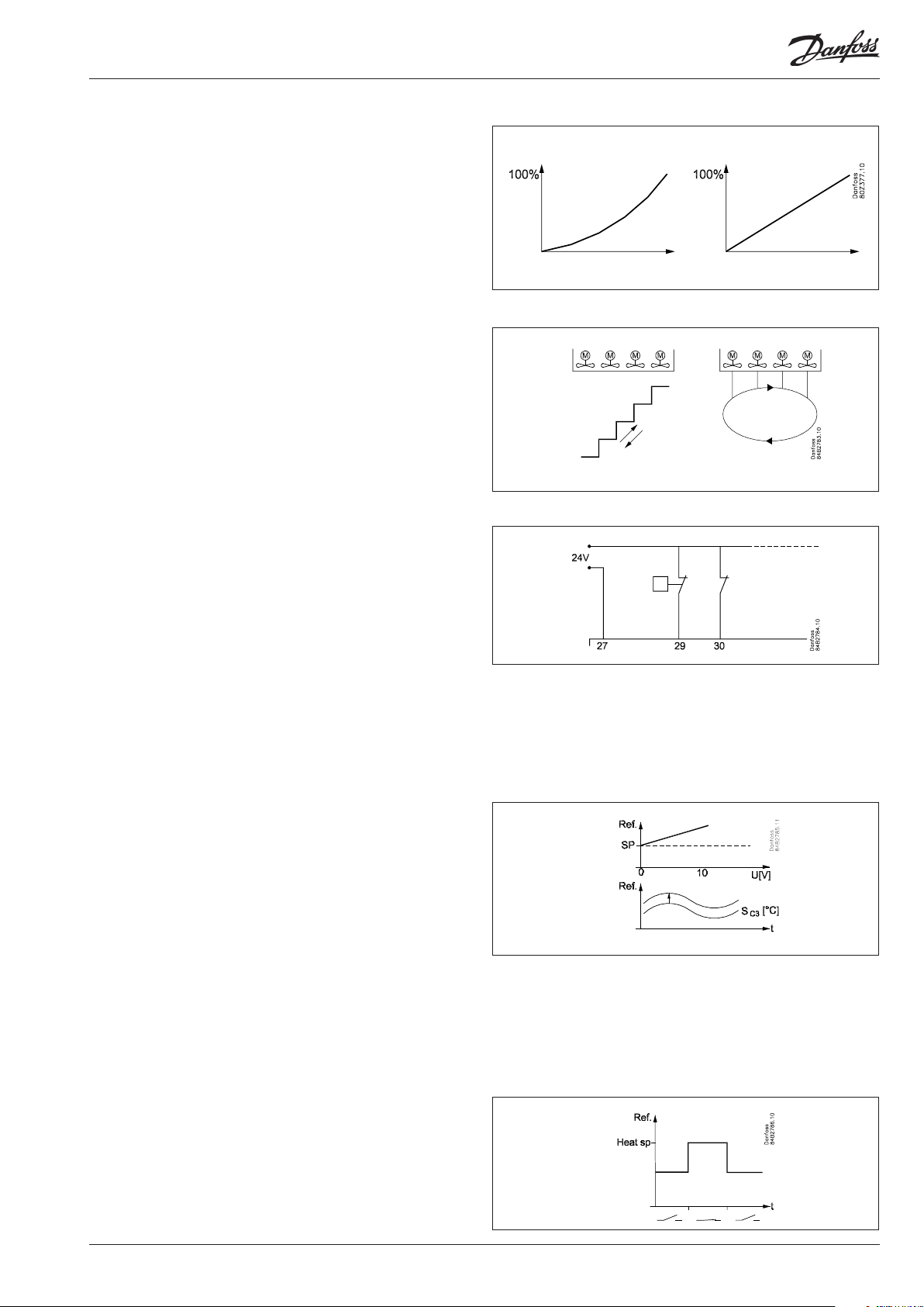
Fan control only (applications 5 and 6)
Capacity regulation takes place via a P or PI regulator, which controls the fans either with step-by-step coupling or speed control.
The analogue output and a frequency converter are used for
speed control. The relay output for fan 1 is used to start/stop the
frequency converter.
In the event of falling capacity, the relay output for fan 1 will be
disabled when the actual capacity has fallen to “FanCap OFF%”.
To achieve hysteresis when starting/stopping the frequency converter, the relay will become enabled when the desired capacity
is the fan capacity above “FanCap OFF%” ( The 10% fan capacity
will correspond to hysteresis of 1 V in the analogue output signal,
when the signal is 0-10 V.)
The P/PI controller only uses regulation settings (proportional
band and integration time) for the fans.
4 Manual RS8EL402 © Danfoss 03-2010 AK-PC 420
Page 5
Linear/non-linear capacity curve for fans
The rst fan step provides relatively more capacity than the subsequent capacity steps. The increase in capacity that an extra step/
speed will generate falls gradually, as more and more steps are
connected/the speed is increased.
The fan regulation therefore has a crooked capacity curve, which
provides optimal reinforcement at both high and low capacities.
However, for some systems a straight curve is required for capacity
regulation, e.g. if the analogue signal is used for more than controlling fans. In this instance the capacity curve can be set at linear.
(The capacity curve for the three-way valve will always be straight.)
Step-by-step coupling of fans
The fans can either be connected in the sequence dened for
them (sequentially) or they can be connected in rotation (sequentially with alternating start).
In sequential operation all fans are enabled at least once every 24
hours, so no fan rusts up due to being inactive for a longer period
of time.
In rotation the various fans take turns in being rst.
Monitoring fans
The controller must receive a signal of the status of each dened
condenser step’s safety circuit. The signal is taken directly from the
safety circuit and connected to a “DI” input.
If the safety circuit is broken, the controller will lose the signal and
emit an alarm.
The associated relay output will not be disconnected. The reason
is that fans are often connected in pairs, but with one single safety
circuit. If there is a fault in one fan, the other will continue to operate.
If no monitoring is desired, the input must be permanently wired
at 24 V.
Reference
Regulation reference
The regulation reference can be dened in one of the following
two ways:
• Fixed setting
The set point for the regulation sensor is set in °C.
If displacement is required, the reference can be displaced
with a 0-10 V signal. During setup you dene how great the
displacement is to be at the signal’s max. and min. value.
• Floating reference according to outdoor temperature
This function allows the reference to vary according to the
outdoor temperature within a dened range.
The outdoor temperature is measured with the Sc3 sensor,
and the reference will always fall within a xed value (min. tm)
above the measured outdoor temperature.
Heat recovery
When heat recovery is enabled via the digital input, the reference
will switch to another set point “Heat SP”, although this too can
be overridden via the external 0-10 V signal. At the same time the
relay for heat recovery is enabled, which then transmits a signal to
either a pump or a valve. The reference's max. value (r30) is overriden from the set value to 99.9° C.
If heat recovery is in progress and the temperature by the regulation sensor is lower than the reference’s set minimum value, the
following happens (see also the following section on limiting the
reference):
AK-PC 420 Manual RS8EL402 © Danfoss 03-2010 5
Page 6
The heat recovery relay is disconnected and can only be re-enabled once the temperature by the regulation sensor has reached 2
K above the reference’s minimum setting.
Ramp function
To avoid overswing and underswing of the reference, a ramp
function has been included to guarantee that the reference cannot
change more quickly than the preset ramp in Kelvin/minute.
Limitation of reference
To protect against regulation reference that is too high or too low,
a limit must be set for the reference. The limit is valid under normal
regulation, but is increased during heat recovery to 99.9° C.
The upper limit is always an absolute value. The lower limit can
either be an absolute value or it can vary in accordance with the
outside temperature Sc3 whereby the limit has a xed value ("r56,
Min tm") above the outside temperature. This means that a reference below the minimum value, making all fans run continuously,
can be avoided.
Ref. Max.
Ref. Min.
Ref. Max.
P or PI regulation with oating or xed reference
See appendix.
Safety functions
Monitoring of condensation pressure
The controller has a safety function that provides protection
against the condensation pressure being too high.
The function can be enabled in two ways.
• Digital input - HP safety
When the digital input is connected, full capacity is cut in to
both fans and three-way valve. An alarm is emitted at the same
time.
The capacity remains cut in until the digital input is interrupted, at which point the alarm is also cancelled. The digital
input can possibly be connected to an external safety pressure
control.
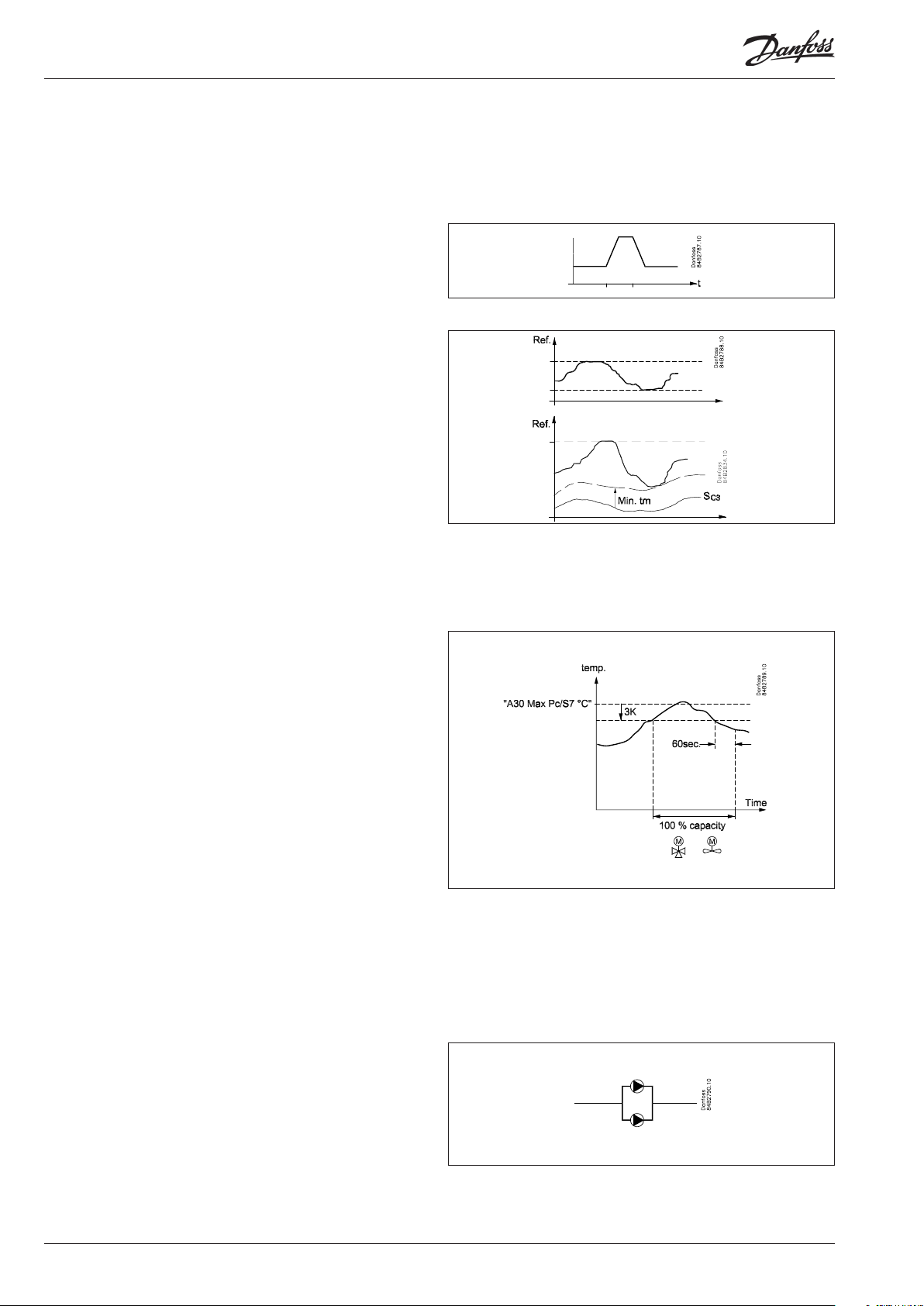
• Measuring the Pc/S7 temperature
This function always uses condensation pressure Pc if the
pressure signal is connected. If Pc is not tted, brine return
temperature S7 is used instead.
The function cuts in all condenser steps and emits an alarm
if the measured temperature is higher than 3 K below the set
limit “S7/Pc max ”.
Normal capacity regulation is restored when the temperature
(pressure) has once more fallen to 3 K below the limit, and a
delay time of 60 seconds has passed.
Ref. Min.
Pump controL
The controller can control and monitor one or two pumps that
circulates the brine.
If two pumps are used and operating time equalisation is selected,
the controller can also execute a switch between the two pumps if
operating alarms occur.
Pump selection is performed using the following settings:
0: Both pumps are stopped
1: Pump 1 is started
2: Pump 2 is started
3: Both pumps are started
4: Automatic switch between the pumps is permitted. Start before
stop
5: Automatic switch between the pumps is permitted. Stop before
start
6 Manual RS8EL402 © Danfoss 03-2010 AK-PC 420
Page 7

Automatic switch between the pumps. Start before stop
(only for setting = 4)
This setting allows a rotation between the two pumps, enabling a
kind of operating time equalisation. The period time between the
pump switches can be set as “p37 PumpCycle”.
When switching, the pump will be kept running for the time “p36
PumpDel” until it stops.
Automatic switch between the pumps. Stop before start
(only for setting = 5)
This setting allows a rotation between the two pumps, enabling a
kind of operating time equalisation. The period time between the
pump switches can be set as “p37 PumpCycle”.
When switching, the pumps will be stopped in the time "p36
PumpDel".
Monitoring pumps
The controller monitors the pumps’ operation via the safety input
“Flowswitch”. The signal may, for example, originate from a pressure dierence pressure switch or a ow switch.
Also set a delay time to dene how the alarm is to be activated.
The delay time is the time from when the input loses the signal
until the controller emits an alarm and executes a pump switch if
necessary.
Special information about operating time equalisation
If the pumps are operating with operating time equalisation, the
controller can perform a switching of the pumps in the event of
a lack of ow (however, the pump switch will only be performed
when the delay time on the alarm has expired).
Depending on whether the pump switch recties the alarm situation or not, the following happens:
1) The pump switch recties the alarm situation
If the pump switch recties the alarm situation, the non-faulty
pump, which is now in operation, will run until the normal cycle
time has expired. It then switches back to the “faulty pump”, as
it is assumed that this has been repaired. At the same time the
alarm situation is reset (the alarm is acknowledged).
If the “faulty pump” has not been repaired, another alarm will be
triggered and cause one more switch to the non-faulty pump.
This is repeated until the situation has been rectied.
2) The pump switch does not rectify the alarm situation
If, however, the alarm is still active after the pump switch, the
controller will also emit an alarm for the other pump. At the
same time both pump outputs are enabled in an attempt to
create sucient ow for the alarm situation to be rectied. The
controller will then have both pump outputs enabled until the
normal cycle time has expired. A normal pump switch is then
conducted and the active alarms are reset.
Separate alarm priorities can be set for the failure of one pump
and the failure of both pumps. See section entitled “Alarms and
messages”.
AK-PC 420 Manual RS8EL402 © Danfoss 03-2010 7
Page 8

Survey of functions
Function Para-
meter
Normal display
If the two displays are mounted:
The regulation temperature is displayed on EKA 164 (the one with buttons) (Pc or S7
or S8)
Pc will be shown on EKA 163. Both readouts will be in temperature
Reference Condenser control
Unit
Here you can select whether the display is to indicate temperatures in °C or °F
0: Will give °C / bar
1: Will give °F / psig
Start/stop of refrigeration
Start/stop of refrigeration may also be performed with an external contact function
connected to the input named “ON input”. (The input must be wired).
Set point
When “r33 ctrl.mode” is set at 1 or 3, it is regulated according to the set value + a possible displacement from a 0-10 V signal.
See also page 18.
Reference variation. See also page 18.
Regulation with setting 1 (or 2 if the reference is to vary with the outdoor temperature) will give the best regulation if the system is in balance. But if a lot of fans are
connected, it may be necessary to select setting 3 instead (or 4, if there is regulation
with the outdoor temperature). (Settings 3 and 4 will generally be preferable if a oset can be accepted between the reference and the actual regulation temperature)
1: No change of the reference. Regulation based on set setpoint + displacement with
a 0-10 V signal.
If there is a heat recovery signal, the reference will switch to the preset set point in
"r64".
2: Outdoor temperature forms part of the reference. The outdoor temperature is
measured with Sc3 sensor and the reference will always have a xed value “r56 Min
tm K” over the measured outdoor temperature.
If there is a heat recovery signal, the reference will switch to the preset set point in
"r64".
Setting 1 and 2 operate with a PI regulation, but if the system is unstable and the PI
regulation not satisfactory the I element may be left out, so that the controller will be
with P regulation only.
3: As 1, but with P regulation (xp-band)
4: As 2, but with P regulation (xp-band)
5: As for 1, but with a minimum reference limit in accordance with outdoor tempera-
ture Sc3
6: As for 3, but with a minimum reference limit in accordance with outdoor temperature Sc3
Reference
The regulation reference is shown here.
Set point limitation
With these settings the setpoint can only be set between the two values.
(This also applies to regulations where the Xp band lies above the reference).
Max. permissible setpoint value. (Is set as an absolute value)
Min. permissible setpoint value. (Is set as an absolute value when "r33" = 1-4)
Correction of pressure measurement Pc
An oset adjustment of the registered pressure can be made.
Dimensioning temperature Min tm
The mean temperature dierence across the condenser at low capacity (tm dierence at max. load). This is the temperature dierence between the air and condensing
temperature.
When “r33 Ctrl. Mode” is set at 2 or 4, regulation takes place according to a reference
that is “Min tm” over the measured outdoor temperature.
Reading of regulation temperature
This is where you can see the actual temperature being measured by the sensor chosen for capacity regulation. The value is displayed in °C.
Set point value for heat recovery
When a heat recovery signal is received, regulation takes place according to the value
set here + any displacement via 0-10 V signal.
Average value for reference changes
A switch in the reference will be ramped up or down over this period of time. Set in
Kelvin/minute.
Parameter by operation via
data communication
S7 °C
Pc °C
S8 °C
r05 Unit
(In AKM only °C is used, whatever the
setting)
r12 Main Switch
r28 Set Point °C
r33 Ctrl. mode
r29 Ref. °C
r30 RefMax °C
r31 RefMin °C
r32 AdjustPc
r56 Min tm K
r58 Ctrl temp
r64 Heat SP°C
r65 RefRamp
8 Manual RS8EL402 © Danfoss 03-2010 AK-PC 420
Page 9

Reference displacement at max. signal (Ext. ref.)
Here the value is set by which the reference is to be displaced when the input signal
Ext. ref. is max. (10 V).
Reference displacement at min. signal (Ext. ref.)
Here the value is set by which the reference is to be displaced when the input signal
Ext. ref. is min. (0 V).
Correction of signal from S7
Compensation possibility due to long sensor cable
Correction of signal from S8
Compensation possibility due to long sensor cable
Condenser capacity Condenser cong.
Denition of condenser and number of fans (may only be set if step-by-step
coupling is being run, i.e. “o61 Applic mode” is set at 1, 3 or 5).
Here you set how many fan steps are to be used for regulation (to max. 6).
1-6: All fans are connected with relays. Relay 1 is assigned fan 1, the next one number
2, etc.
7-10: Not used
11-16: Total number of fan relays (as 1-6), but here the starting sequence is altered
after each time all fans have been stopped.
NB
The controller must receive a signal of the status of each condenser step’s safety
circuit. The signal must be connected to the associated DI input.
Denition of output voltage to valve/speed control
Output signal is 0-10 V or 10-0 V. The signal can be either linear or un-linear, so that it
can be adapted to the desired characteristics.
1: 0-10 V, linear
2: 10-0 V linear (not at shunt and fan speed)
3: 0-10 V, unlinear
4: 10-0 V unlinear (not at shunt and fan speed)
Regulation parameters
r68 ExtRefMax
r69 ExtRefMin
r72 Adjust S7
r73 Adjust S8
c29 Fan mode
c34 AO type
- - - - Cond Cap %
Read cut-in condenser capacity
Proportional band xp for valve regulation (P = 100/Xp)
If the Xp value is increased, the regulation becomes steadier
I: Integration time Tn for valve regulation
If the Tn value is increased, the regulation becomes steadier
Manual control of condenser capacity
This sets the capacity that is to be cut in when switching to manual control.
Manual control
Manual control of the condenser capacity is enabled here.
When set to ON, the capacity that is specied in “n52” is cut in.
The setting will fall back to “O” if the Main switch is set to O or if there is a power
outage.
P: Proportional band xp for fan regulation (P = 100/Xp)
If the Xp value is increased, the regulation becomes steadier
I: Integration time Tn for fan regulation
If the Tn value is increased, the regulation becomes steadier
Capacity overlap between valve and fans
In valve regulation the rst 50% of the capacity is controlled by the valve. When the
valve is fully open continues with fan cut-in.
The fans then take over.
If the fans are to start before the three-way valve is fully open, a value must be set
that is lower than 50%.
If the fans are only to start after the three-way valve is fully open, a value must be set
that is higher than 50%.
Alarm Alarm settings
The controller can give alarm in dierent situations. When there is an alarm the lightemitting diodes (LED) will ash on the display and the alarm relay will cut in.
Pc max. (Alarm and safety function, see also page 18.)
Here you set when the alarm at too high condensing pressure is to enter into eect.
The value is set as an absolute value.
Alarm delay DI1 (an interrupted input will give alarm).
The time delay is set in minutes. At min. setting the alarm is cancelled.
n04 Valve Xp K
n05 Valve Tn s
n52 ConManCap%
n53 ConManCap
n60 Fan XP K
n61 Fan Tn s
n62 FanCap OFF %
A30 Max. Pc. / S7
A27 DI1AlrmDelay
AK-PC 420 Manual RS8EL402 © Danfoss 03-2010 9
Page 10

Alarm delay DI2 (an interrupted input will give alarm).
The time delay is set in minutes. At min. setting the alarm is cancelled.
Alarm delay DI3 (an interrupted input will give alarm).
The time delay is set in minutes. At min. setting the alarm is cancelled.
Pump alarm delay
The time delay is set in seconds. At min. setting the alarm is cancelled.
Give the top button a brief push to zeroset the alarm and to have the message shown
on the display.
Miscellaneous Miscellaneous
Choice of application
The regulator can be congured in various ways. The application that is required out
of the six applications available is set here.
1: S7 + 3-way valve + Step of fans
2: S7 + 3-way valve + VSD (speed) of fans
3: Pc + 3-way valve + Step of fans
4: Pc + 3-way valve + VSD (speed) of fans
5: S8 + Step of fans
6: S8 + VSD (speed) of fans
Sensor type (Sc3, S7 and S8)
Normally a Pt1000 sensor with great signal accuracy is used for temperature measurement. But a PTC sensor may also be used (r25 = 1000) in special situations.
0=Pt1000
1=PTC1000
Pressure transmitter’s working range
Depending on the pressure, a pressure transmitter with a given working range is
used. This working range must be set in the controller (e.g.: -1 to 34 bar
The values must be set in bar if display in °C has been selected. And in psig, if °F has
been selected.
Pc-Min. value o47 PcMinTrsPres
A28 DI2AlrmDelay
A29 DI3AlrmDelay
A63 Pump Al. Del
Reset alarm
The function zerosets all alarms when
set in pos. ON.
With data communication the importance of the individual alarms can be
dened. Setting is carried out in the
“Alarm destinations” menu.
o61 Applic.Mode
o06 Sensor type
If the values are to be set from the
AKM programme, they must be set in
bar.
Pc-Max. value o48 PcMaxTrsPres
Use of DI4 input
The digital input can be connected to a contact function, and the contact can now be
used for one of the following functions:
Setting / function:
0: DI input not used
1: Safety signal from high-pressure pressure control. If the signal is cut o, all capacity
is cut in. There is no time delay.
Operating hours
The operating hours for the pomp relays can be read and set in the following menus.
The read value is multiplied by 1000 to obtain the number of hours (fx. shows 2.1 for
2100 hours). On reaching 99.9 hours the counter stops and must now be reset to, say,
0. There will be no alarm or error message for counter overow.
Value for relay number 7 (pump 1) o52 DO7 run hour
Value for relay number 8 (pump 2) o53 DO8 run hour
Refrigerant setting (only if a Pc pressure transmitter is tted)
Before refrigeration is started, the refrigeration must be dened. You may choose
between the following refrigerants:
1=R12. 2=R22. 3=R134a. 4=R502. 5=R717. 6=R13. 7=R13b1. 8=R23. 9=R500.
10=R503. 11=R114. 12=R142b. 13=User dened. 14=R32. 15=R227. 16=R401A.
17=R507. 18=R402A. 19=R404A. 20=R407C. 21=R407A. 22=R407B. 23=R410A.
24=R170. 25=R290. 26=R600. 27=R600a. 28=R744. 29=R1270. 30=R417A.
31=R422A. 32=R413A. 33=R422D. 34=R427A. 35=R438A.
Warning: Wrong selection of refrigerant may cause damage to the compressor.
Other refrigerants: Select setting 13 here, and subsequently three factors have to be
set – fac1, fac2 and fac3 – via AKM.
o22 DI4 control
(In the AKM display the hour number
has not been multiplied)
o30 Refrigerant
10 Manual RS8EL402 © Danfoss 03-2010 AK-PC 420
Page 11

Manuel operation (only via display and only when regulation has stopped
(r12=o))
From this menu the relays can be cut in and out manually. 0 gives no override, but a
number between 1 and 10 will cut in a belonging relay. 1 will cut in relay number 1, 2
relay 2, etc.
11-18 will produce voltage on the analog output. Setting 11 will give a voltage of
1.25 V, setting 12 will give 2.5 V, etc.
Frequency
Set the net frequency.
Use of S8 sensor
If application (o61) is selected to 1, 2, 3 or 4, the S8 sensor can be used for regulation
or for monitoring.
The S8 sensor, which has to be located near by the outlet of the dry cooler, should be
used in the regulation if the distance between the dry cooler and the 3-way-valve is
long. If the S8 sensor is want to be used in the regulation set o96 to ON. Is the S8 sensor not used in the regulation it can be located optional for monitoring purpose (o96
has to be set to OFF).
Address
If the controller is built into a network with data communication, it must have an
address, and the master gateway of the data communication must then know this
address.
These settings can only be made when a data communication module has been
mounted in the controller and the installation of the data communication cable has
been completed.
This installation is mentioned in a separate document “RC8AC”.
The address is set between 1 and 240 (gateway determined) o03
The address is sent to the gateway when the menu is set in pos. ON o04
Access code
If the settings in the controller are to be protected by a numerical code, you can set a
numerical value between 0 and 100. If not, you can cancel the function with setting
OFF.
Status on relay outputs
Status on relay 1 (fan 1 or start/stop of speed control) p25 Fan 1 status
Status on relay 2 (fan 2) p26 Fan 2 status
Status on relay 3 (fan 3) p27 Fan 3 status
Status on relay 4 (fan 4) p28 Fan 4 status
Status on relay 5 (fan 5) p29 Fan 5 status
Status on relay 6 (fan 6) p30 Fan 6 status
Status on relay 7 (pump 1) p31 Pump 1
Status on relay 8 (pump 2) p32 Pump 2
Status on relay 9 (Heat recovery) p33 Heat recovery
Status on relay 10 (alarm) p34 Alarm
Pump control
Here you dene how the pumps are to be controlled:
0: Both pumps are stopped
1: Only pump 1 is started
2: Only pump 2 is started
3: Both pump 1 and pump 2 are started
4: Automatic switch between pumps 1 and 2. Start before stop
5: Automatic switch between pumps 1 and 2. Stop before start
Pump-stop delay
During pump switching both pumps can run for a short overlap. Here you set how
many seconds.
Run period in cyclic operation
This is where you set the number of hours the pump will run. You then switch over to
the other pump. Repeat this.
Status on DI 1 u10 DI 1 Status
Status on DI 2 u37 DI 2 Status
Reading temperature at Sc3 sensor u44 Sc3 Status
Status on DI 3 u87 DI 3 Status
Status on DI 4 u88 HP safety
Status on DI 5 u89 Heat recov.
Reading temperature at S8 sensor u93 S8 temp
Status on Flow switch input u94 Flow switch
Read o the actual reference displacement received in the analogue input Ext. Ref. u96 Ext. Ref°C
Read o the value on the analogue output to the valve/frequency converter. u97 AO Volt
Reading temperature at S7 sensor u98 S7 temp
o18 - - -
o12 50 / 60 Hz
(50=0, 60=1)
o96 S8 optional
Following installation of a data communication module, the controller can
be operated on a par with the other
controllers in ADAP-KOOL® refrigeration controls.
o05
p35 Pump ctrl.
p36 Pump del.
p37 Pump cycle
AK-PC 420 Manual RS8EL402 © Danfoss 03-2010 11
Page 12

Operating status
The controller goes through some regulating situations where it is just waiting for the next
point of the regulation. To make these “why is nothing happening” situations visible, you can
Ctrl state
(0 = regulation)
see an operating status on the display. Push briey (1s) the upper button. If there is a status
code, it will be shown on the display. The individual status codes have the following meanings
S10: Regulation stopped with the internal and external start/stop 10
S25: Manual regulation of outputs 25
Alarm messages Alarms "Destinations"
A11: No refrigerant has been selected (cf. o30) A11 No RFG Sel
A17: High Pc A17 Hi Pc alarm
A28, A29, A30: External alarm. Interrupted signal on input "DI1" /2/3 A28 ...... A30 DI_ Alarm
A34, A35, A36, A37, A46, A47: Fan alarm. Fan 1, 2, 3, 4, 5, 6 A34 ...... A37, A46, A47 Fan_fault
A45: Regulation stopped with setting or with external switch A45 Stand by
A77: Interrupted signal on input "Flow switch" while pump 1 was operating A77 Pump 1 fault
A78: Interrupted signal on input "Flow switch" while pump 2 was operating A78 Pump 2 fault
A79: Interrupted signal on input "Flow switch" while pump 1 and 2 were operating A79 PMP1&2 fault
E1: Error in the controller E1 Ctrl. fault
E2: Control signal outside the range (short-circuited/interrupted) E2 Out of range
Safety functions
Criterion Reference / control sensor Capacity
Pc or S7 > Pc/S7 max (A30) - 3 No change 100% capacity until the signal has fallen below the
Pc signal failure S7 is used instead and the reference is lowered 5 K. Normal regulation
S7 signal failure Pc is used instead and the reference is raised 5 K. Normal regulation
Pc and S7 signal failure No change 100% capacity
Sc3 signal failure The oating reference is removed, and regulation takes
place according to the set value for the reference – “r29”.
S8 signal failure No change When using app. 1-4, regulation continues without
limit for 60 seconds.
Normal regulation
S8 sensor.
When using app. 5-6, 100% capacity is cut in.
12 Manual RS8EL402 © Danfoss 03-2010 AK-PC 420
Page 13

Operation
Data communication
If the controller is extended with data communication, the operation can be performed from a system unit. The parameter names
for the functions can be viewed in the right-hand column on
pages 8–12.
The importance of the alarms that are sent can be dened with
the setting: 1 (High), 2 (Medium), 3 (Low) or 0 (No alarm).
Operation via external display
The values will be shown with three digits, and with a setting you
can determine whether the pressures are to be shown in °C or in
°F (bar/psig).
There are two options for the display.
EKA 164
EKA 164
To operate the controller and view the regulation temperature.
If the lowermost key is pressed, the temperature from one of the
other sensors will be shown briey in the display.
Regulation Normal display Alternative view
Regulation sensor (lowermost key)
1 and 2 S7 Pc
3 and 4 Pc S7
5 and 6 S8 S7
EKA 163
The buttons on the display
When you want to change a setting, the upper and the lower
buttons will give you a higher or lower value depending on the
button you are pushing. But before you change the value, you
must have access to the menu. You obtain this by pushing the
upper button for a couple of seconds - you will then enter the
column with parameter codes. Find the parameter code you want
to change and push the middle button. When you have changed
the value, save the new value by once more pushing the middle
button.
EKA 163
If the alternative temperature is to be shown constantly, a display
without operating keys can be connected.
Or short:
1. Push the upper button (long push) until a parameter is shown
2. Push one of the buttons and nd the parameter you want to
change
3. Push the middle button until the setting value is shown
4. Push one of the buttons and select the new value
5. Push the middle button again to conclude the setting
( A brief pushing will show the active alarm codes. See page 15.)
AK-PC 420 Manual RS8EL402 © Danfoss 03-2010 13
Page 14

Menu survey
Conguration parameters can only be set when the regulation is
stopped, r12=0.
SW: 1.2x
Para-
Function
Normal display
A display of the regulated temperature
can be seen in EKA 164. (display with
buttons)
Shows Pc in EKA 163 - °C
Reference
Select unit (0=bar and °C, 1=Psig and
°F)
Start/Stop of regulation r12 OFF ON OFF
Set regulation setpoint r28 -25°C 75°C 30°C
Shows the total reference r29 °C
Limitation: reference max. value r30 -99.9°C 99.9°C 55.0°C
Limitation: reference min. value r31 -99.9°C 99.9°C -99.9°C
Correction of signal from Pc-sensor r32 -50 K 50 K 0.0
Pc reference variation.1 and 2 are PIregulation
1: Fixed reference. “r28” is used
2: Variable reference. Outdoor temperature (Sc3) included in the reference
3: As 1, but with P-regulation (Xp-band)
4: As 2, but with P-regulation (Xp-band)
5: As 1, but with min.-reference acc. to
outdoor temperature
6: As 3, but with min.-reference acc. to
outdoor temperature
The mean temperature dierence
across the condenser at the lowest
relevant capacity (min tm K)
This is where you can see the actual
temperature that is part of the regulation.
Set point settings for heat recovery r64 -25°C 75°C 35°C
Average period for reference changes. r65
Displacement of reference at external
signal = 10 V
Displacement of reference at external
signal = 0 V
Correction of signal from S7-sensor r72 -50 K 50 K 0.0
Correction of signal from S8-sensor r73 -50 K 50 K 0.0
Capacity
Denition of fan relay
1-6: Total number of fan relays in
sequential operation.
7-10: Not used
11- 16: Total number of fan relays in
cyclic operation.
Denition of the analoge output voltage 0-10 V
1: 0-10 V, linear
2: 10-0 V, linear
3: 0-10 V, unlinear
4: 10-0 V, unlinear
Proportional band Xp for (P= 100/Xp)
valve regulation
I: Integration time Tn for valve regulation
Cutin condenser capacity with manual
control. See also “n53”
Min. Max. Fac.
meter
- °C
r05 0 1 0
r33 1 6 1
r56 3.0 50.0 8.0
r58 °C
0.1 K/
min.
r68 -50 K 50 K 0.0
r69 -50 K 50 K 0.0
c29 0/OFF 16 0
c34 1 4 1
n04 0.2 K 40.0 K 10.0 K
n05 30 s 600 s 120
n52 0 % 100 % 0
50
K/min.
sett.
10
K/min.
Manual control of condenser capacity
(when ON, the value in “n52” will be
used)
Proportional band Xp for (P= 100/Xp)
fan regulation
I: Integration time Tn for fan regulation n61 30 s 600 s 240
Denition of where the rst fan is
connected. Set as a % of the total
refrigeration capacity. Ex. 50%, if a
three-way valve is also used.
Alarm
Delay time for a DI1 alarm
Delay time for a DI2 alarm A28
Delay time for a DI3 alarm A29
Upper alarm and safety limit for Pc A30 -10 °C 200°C 60.0°C
Pump alarm delay A63 1 s 600 s 15 s
Miscellaneous
Controllers address o03* 1 990
On/o switch (service-pin message) o04* - -
Access code o05
Used sensor type for Sc3, S7 and S8
0=Pt1000, 1=PTC1000
Set supply voltage frequency o12 50 Hz 60 H 0
Manual control of outputs:
0: No override
1-10: 1 will cut in relay 1, 2 relay 2, etc.
11-18: Gives voltage signal on the
analog output. (11 gives 1.25 V, and so
on in steps of 1.25 V
Use of DI4-input
0=not used. 1=Safety signal from high
pressure pressostat
Setting of refrigerant
1=R12. 2=R22. 3=R134a. 4=R502.
5=R717. 6=R13. 7=R13b1. 8=R23.
9=R500. 10=R503. 11=R114.
12=R142b. 13=User dened. 14=R32.
15=R227. 16=R401A. 17=R507.
18=R402A. 19=R404A. 20=R407C.
21=R407A. 22=R407B. 23=R410A.
24=R170. 25=R290. 26=R600.
27=R600a. 28=R744. 29=R1270.
30=R417A. 31=R422A. 32=R413A.
33=R422D. 34=R427A. 35=R438A.
Pc pressure transmitter’s working range
- min. value
Pc pressure transmitter’s working range
- max. value
Operating hours of relay 7 (value time
1000)
Operating hours of relay 8 (value time
1000)
* this setting is only possible if data communication module is mounted in
the controller
n53 OFF ON OFF
n60 0.2 K 40.0 K 20.0 K
n62 0 % 70 % 50 %
0 min.
A27
(-1=OFF)
0 min.
(-1=OFF)
0 min.
(-1=OFF)
1
(0=OFF)
o06 0 1 0
o18 0 18 0
o22 0 1 0
o30 0 35 0
o47 -1 bar 0 bar -1.0
o48 1 bar
o52 0.0 h 99.9 h 0.0
o53 0.0 h 99.9 h 0.0
999
OFF
min.
999
OFF
min.
999
OFF
min.
100 OFF
200
34.0
bar
To be continued
14 Manual RS8EL402 © Danfoss 03-2010 AK-PC 420
Page 15

Selection of application
Regulation sensor and output are:
1: S7 + 3-way valve + Step of fans
2: S7 + 3-way valve + VSD (speed) of
fans
3: Pc + 3-way valve + Step of fans
4: Pc + 3-way valve + VSD (speed) of
fans
5: S8 + Step of fans
6: S8 + VSD (speed) of fans
Use of S8
On: for regulation
O: for monitoring
Service etc.
Status on relay 1 (fan 1) p25
Status on relay 2 (fan 2) p26
Status on relay 3 (fan 3) p27
Status on relay 4 (fan 4) p28
Status on relay 5 (fan 5) p29
Status on relay 6 (fan 6) p30
Status on relay 7 (pump 1) p31
Status on relay 8 (pump 2) p32
Status on relay 9 (heat recovery) p33
Status on relay 10 (alarm) p34
Pump control:
0: Both pumps stops
1: Pump 1 only
2: Pump 2 only
3: Both pump 1 and pump 2
4: 2 pumps + rotation. Start before
stop
5: 2 pumps + rotation. Stop before
start
Pump setting. Operating time with
two pumps when switching takes
place.
Pump setting. After the operating
time you then switch over to the other
pump.
Status on DI1 input u10
Status on DI2 input u37
Read temperature at sensor "Sc3" u44 °C
Status on DI3 input u87
Status on DI4 input u88
Status on DI5 input u89
Read temperature at sensor "S8" u93
Status on "Flow switch"-input u94
Read reference displacement from the
external signal
Read the value of the analogue output
in V
Read temperature at sensor "S7" u98
o61 1 6 1
o96 O/0 On/1 O/0
p35 0 5 1
p36 0 s 60 s 10 s
p37 1 h 500 h 24 h
u96
u97
The controller can give the following messages
E1 Error
message
E2 Regulation is outside the range, or the control
Alarm
A11
message
A17 High Pc
A28 DI 1 alarm. Terminal 46 interrupted
A29 DI 2 alarm. Terminal 47 interrupted
A30 DI 3 alarm. Terminal 49 interrupted
A34 Fan 1 alarm. Terminal 29 is open
A35 Fan 2 alarm. Terminal 30 is open
A36 Fan 3 alarm. Terminal 31 is open
A37
A45 Regulation stopped
A46 Fan 5 alarm. Terminal 33 is open
A47 Fan 6 alarm. Terminal 34 is open
A77 Pump 1 alarm. Terminal 36 interrupted
A78 Pump 2 alarm. Terminal 36 interrupted
A79 Pump 1 and 2 alarm. Terminal 36 interrupted
Status
S10
message
S25 Manual control of outputs
PS Info
Fault in controller
signal is defective
Refrigerant not selected
Fan 4 alarm. Terminal 32 is open
Refrigeration stopped by the internal or external
start/stop function
Access code is required before you have access to
the settings
Messages can be brought up on the display by briey pressing
the uppermost key. If there is more than one alarm, they can be
scrolled through
Factory setting
If you need to return to the factory-set values, it can be done in
this way:
- Cut out the supply voltage to the controller
- Keep the upper and the lower button depressed at the same
time as you recon nect the supply voltage
Factory settings are indicated for standard units (see code numbers, page 1). Other
code numbers have customized settings.
AK-PC 420 Manual RS8EL402 © Danfoss 03-2010 15
Page 16

Connections
Pc: AKS 32R:
1 = Black = +
2 = Blue = 3 = Brown = s
All inputs are low-voltage. All
relay outputs may be highvoltage.
Terminals:
1-2 Supply voltage 24 V a.c.
4- 15 Relay outputs for fan motors
16-19 Relay output to pump 1 and pump 2
20-21 Relay output to heat recovery
22-24 Alarm relay
There is connection between 22 and 24 in alarm situa tions
and when the controller is dead
27-28 24 V signal to start / stop of regulation
27-29 24 V signal from the safety circuit fan 1
27-30 24 V signal from the safety circuit fan 2
27-31 24 V signal from the safety circuit fan 3
27-32 24 V signal from the safety circuit fan 4
27-33 24 V signal from the safety circuit fan 5
27-34 24 V signal from the safety circuit fan 6
27-35 (not used)
27-36 24 V signal from ow switch
37-38 Output signal 0-10 V d.c. to either 3-way valve or frequen-
cy transformer for fans
39-41 Possibility of connecting an external display type EKA 163
for display of Pc
42-44 Possibility of connecting an external display type EKA 164
for operation and temperature display
45-46 DI1 - Contact function for alarm signal
45-47 DI2 - Contact function for alarm signal
48-49 DI3 - Contact function for alarm signal
48-50 HP safety - contact function for receiving of high pressure-
safety signal
51-52 Heat recovery - Contact function for receive of signal to
start of heat recovery
51-53 S7 sensor. Sensor signal from AKS 11, AKS 12 or EKS 111
54-55 Sc3 sensor. Sensor signal from AKS 11, AKS 12 or EKS 111
54-56 S8 sensor. Sensor signal from AKS 11, AKS 12 or EKS 111
57-58 Signal for displacement of reference. 0-10 V d.c.
60-62 Condenser pressure. Voltage signal from AKS 32R.
Data communication
25-26 Mount only, if a data communication module has been
mounted.
For Ethernet communication the plug connection RJ45
must be used. (LON FTT10 can also be connected in this
way.
It is important that the installation of the data communication cable be done correctly. Cf. separate literature No.
RC8AC.
Common Pc signal
If AK-PC 420 is used together with another control for compressors, e.g.:
AK-PC 530
AK-PC 730
AK-PC 840
AK-CH 650
the same AKS 32R can emit a signal to both controls. But in this
case separate 24 V power supplies must be used for the two controllers. In addition to this, the safety limit for “high condensation
pressure” is set at the same value in the two controllers.
16 Manual RS8EL402 © Danfoss 03-2010 AK-PC 420
Page 17
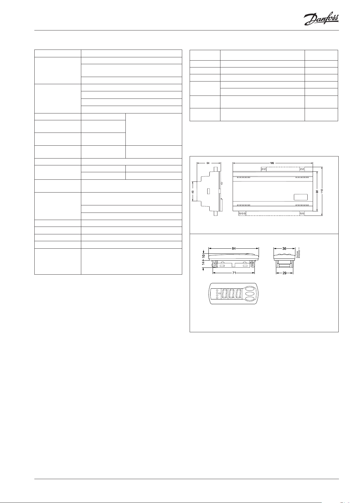
Data Ordering
Danfoss
84B2330.11
Supply voltage 24 V a.c. +/-15% 50/60 Hz, 5 VA
1 pcs. pressure transmitter type AKS 32R
Input signal
Digital input from
contact function.
Relay output for fans 8 pcs. SPST
Relay output for twin
pump
Relay output heat
recovery
Alarm relay 1 pcs. SPDT
Voltage output 0-10 V d.c.
Display outputs
Data communication
Environments
Enclosure IP 20
Weight 0.4 kg
Mounting DIN rail or on wall
Terminals max. 2.5 mm2 multicore
Approvals
3 pcs. temperature sensor input for PT 1000
ohm/0°C or PTC 1000 ohm/25°C
External reference signal: 0-10 V d.c.
1 pcs. for Start/stop of regulation
8 pcs. for monitoring of safety circuits
3 pcs. for alarm function
1 pcs. for start of heat recovery
2 pcs. SPST
1 pcs. SPST
EKA 163 Pc display
EKA 164 Operation, S7 display
Possible to connect a data communication
module
0 - 55°C, during operation
-40 - 70°C, during transport
20 - 80% Rh, not condensing
No shock inuence / vibrations
EU Low voltage Directive and EMC demands re
CE-marking complied with.
LVD-tested acc. to EN 60730-1 and EN 60730-2-9
EMC-tested acc. to EN61000-6-2 and 3
AC-1: 3 A (ohmic)
AC-15: 2 A (inductive)
AC-1: 6 A (ohmic)
AC-15: 3 (inductive)
Type Function Ordering
AK-PC 420 Capacity controller for dry cooler 084B8008
EKA 163B Display unit 084B8574
EKA 164B Display unit with operation buttons 084B8575
EKA 174
EKA 178B
Montage
AK-PC 420
Cable for display unit 2 m, 1 pcs. 084B7298
Cable for display unit 6 m, 1 pcs. 084B7299
Data communication module, LON RS
485 (with galvanic separation)
Data communication module, MOD-bus
(with galvanic separation)
084B7124
084B8571
Pressure transmitter / temperature sensor
Please refer to catalogue RK0YG...
Only for front mounting (IP 40)
Only connection via plugs
Display type EKA 163 / EKA 164
Installation considerations
Accidental damage, poor installation, or site conditions, can give
rise to malfunctions of the control system, and ultimately lead to a
plant breakdown.
Every possible safeguard is incorporated into our products to
prevent this. However, a wrong installation, for example, could still
present problems. Electronic controls are no substitute for normal,
good engineering practice.
Danfoss will not be responsible for any goods, or plant components, damaged as a result of the above defects. It is the installer's
responsibility to check the installation thoroughly, and to t the
necessary safety devices.
Special reference is made to the necessity of signals to the
controller when the compressor is stopped and to the need of
liquid receivers before the compressors.
Your local Danfoss agent will be pleased to assist with further
advice, etc.
AK-PC 420 Manual RS8EL402 © Danfoss 03-2010 17
Page 18

Appendix - Reference and regulation
The regulation functions are explained in more detail below.
With parameter r33 Ctrl. Mode it is possible to choose between six dierent forms of regulation.
As a starting point 1, 2 or 5 are recommended. However, if the system is unstable it might be necessary to switch to 3, 4 or 6.
r33 Ctrl.
1. PI regulation. Fixed reference i.e. constant condensing pressure.
2. PI regulation. Floating reference with outdoor temperature Sc3 i.e. variable condensing pressure.
3. As ”1”, but with P regulation. A higher condensing pressure than indicated by the reference must be accepted here.
4. As ”2”, but with P regulation. A higher condensing pressure than indicated by the reference must be accepted here.
5. and 6. As 1 and 3, but with outdoor temperature dependent min. reference.
The dierent regulation modes are as follows:
(For the sake of simplicity, in the example no consideration is given to any possible overriding with external reference signal 0-10 V.)
type
1 PI r28 SP+Ext. Ref r64 SP+Ext. Ref r31 Ref Min. r30 Ref Max.
2 PI Sc3+Min.tm r64 SP+Ext. Ref r31 Ref Min. r30 Ref Max.
3 P r28 SP+Ext. Ref r64 SP+Ext. Ref r31 Ref Min. r30 Ref Max.
4 P Sc3+Min.tm r64 SP+Ext. Ref r31 Ref Min. r30 Ref Max.
5 PI r28 SP+Ext. Ref r64 SP+Ext. Ref Sc3+Min. tm K r30 Ref Max.
6 P r28 SP+Ext. Ref r64 SP+Ext. Ref Sc3+Min. tm K r30 Ref Max.
No heat recovery Heat recovery Minimum Maximum
1. PI regulation with xed reference
Reference Reference delimitation
Important setting to avoid
unwanted alarms
When r33 = 1,2 or 5:
Pc Ref max. must be set at least 5 K
below Pc max. (A30).
When r33 = 3, 4 or 6:
Pc Ref max. must be set at least (”n04
Valve Xp” + ”n60 Fan Xp” +5) K below Pc
max. (A30).
Heat recovery = on
In PI regulation the controller will make sure that the actual regulation
temperature deviates as little as possible from the actual reference.
The reference at any time, on the basis of which the controller regulates,
can be seen in ”r29”.
During normal regulation the setting “r28 SetPoint” is used as a reference.
For heat recovery the reference is changed to R64 Heat SP °C, and r30 is
raised to 99.9°C
2. PI regulation with oating reference
Heat recovery = on
In PI regulation the controller will make sure that the actual regulation
temperature deviates as little as possible from the actual reference.
The reference is at a xed value (r56 Min tm K) above the actual measured
outdoor temperature Sc3 and can be seen in “r29 Ref °C”.
If the outdoor temperature falls one degree, the reference will also fall
one degree. For heat recovery the reference is changed to r64 Heat SP °C,
and r30 is raised to 99.9°C
Raising/lowering of the reference takes place via a ramp function dened
at “r65 RefRamp”.
The capacity of the three-way valve is controlled via regulation parameters
“n04 Valve Xp” and “n05 valve Tn s”, and the fans are controlled via regulation parameters “n60 Fan Xp” and “n61 Fan Tn s”.
Raising/lowering of the reference takes place via a ramp function dened
at “r65 RefRamp”.
If there is a sensor failure on the outdoor temperature sensor, the reference
will switch to the setting of “r28 SetPoint”.
The capacity of the three-way valve is controlled via regulation parameters
“n04 Valve Xp” and “n05 valve Tn s”, and the fans are controlled via regula-
tion parameters “n60 Fan Xp” and “n61 Fan Tn s”.
18 Manual RS8EL402 © Danfoss 03-2010 AK-PC 420
Page 19

3. P regulation with xed setting
Heat recovery = on
As point 1, but with P regulation the actual regulation temperature will
always deviate in relation to the actual reference. The reason is that the
actual cut-in capacity is solely dependent on how far the measured
regulation temperature is from the actual reference.
The capacity of the three-way valve is controlled via proportional band
“n04 Valve Xp” and the fans are controlled via proportional band “n60
4. P regulation with oating reference
Heat recovery = on
As point 2, but with P regulation the actual regulation temperature will
always deviate in relation to the actual reference. The reason is that the
actual cut-in capacity is solely dependent on how far the measured
regulation temperature is from the actual reference.
The capacity of the three-way valve is controlled via proportional band
“n04 Valve Xp” and the fans are controlled via proportional band “n60
Fan Xp”. This means that the three-way valve will be fully open when the
temperature is “n04 S7/Pc Xp” over the actual reference, and the fans will
provide full capacity when the temperature is “n04 S7/Pc Xp” + “n60 S8 Xp”
above the actual reference.
The cutin and cutout of fans are shown in the drawing.
If the entire fan capacity is controlled by speed regulation, the capacity will
be indicated on the broken line.
Fan Xp”. This means that the three-way valve will be fully open when the
temperature is “n04 S7/Pc Xp” over the actual reference, and the fans will
provide full capacity when the temperature is “n04 S7/Pc Xp” + “n60 S8 Xp”
above the actual reference.
The cutin and cutout of fans are shown in the drawing.
If the fan capacity is controlled by speed regulation, the capacity will be
indicated on the broken line.
AK-PC 420 Manual RS8EL402 © Danfoss 03-2010 19
Page 20

5. PI regulation with xed reference and with min. reference which depends on the outdoor temperature
Heat recovery = on
In PI regulation the controller will make sure that the actual regulation
temperature deviates as little as possible from the actual reference.
The reference at any time, on the basis of which the controller regulates,
can be seen in ”r29”.
During normal regulation the setting “r28 SetPoint” is used as a reference.
Ref. min. = Sc3 + Min. tm K
For heat recovery the reference is changed to R64 Heat SP °C, and r30 is
raised to 99.9°C
Raising/lowering of the reference takes place via a ramp function dened
at “r65 RefRamp”.
The capacity of the three-way valve is controlled via regulation parameters
“n04 Valve Xp” and “n05 valve Tn s”, and the fans are controlled via regulation parameters “n60 Fan Xp” and “n61 Fan Tn s”.
6. P regulation with xed setting and with min. reference which depends on the outdoor temperature
Heat recovery = on
As point 1, but with P regulation the actual regulation temperature will
always deviate in relation to the actual reference. The reason is that the
actual cut-in capacity is solely dependent on how far the measured
regulation temperature is from the actual reference.
The capacity of the three-way valve is controlled via proportional band
“n04 Valve Xp” and the fans are controlled via proportional band “n60
Ref. min. = Sc3 + Min. tm K
Fan Xp”. This means that the three-way valve will be fully open when the
temperature is “n04 S7/Pc Xp” over the actual reference, and the fans will
provide full capacity when the temperature is “n04 S7/Pc Xp” + “n60 S8 Xp”
above the actual reference.
The cutin and cutout of fans are shown in the drawing.
If the entire fan capacity is controlled by speed regulation, the capacity will
be indicated on the broken line.
Danfoss can accept no responsibility for possible errors in catalogues, brochures and other printed material. Danfoss reserves the right to alter its products without notice. This also applies to products
already on order provided that such alternations can be made without subsequential changes being necessary in specications already agreed.
All trademarks in this material are property of the respecitve companies. Danfoss and Danfoss logotype are trademarks of Danfoss A/S. All rights reserved.
20 Manual RS8EL402 © Danfoss 03-2010 AK-PC 420
FC-SPMC
 Loading...