


Identication
Principle
Instructions
AK-PC 351
IP 20
-20 - 60°C
(0 - 140°F)
RH max. 90% non condensing
080G0289 = 24 V a.c. / d.c. 9 VA
Dimensions
RI8RB2ML 09-2014
DIN rail only (IP 20)
ENGLISH
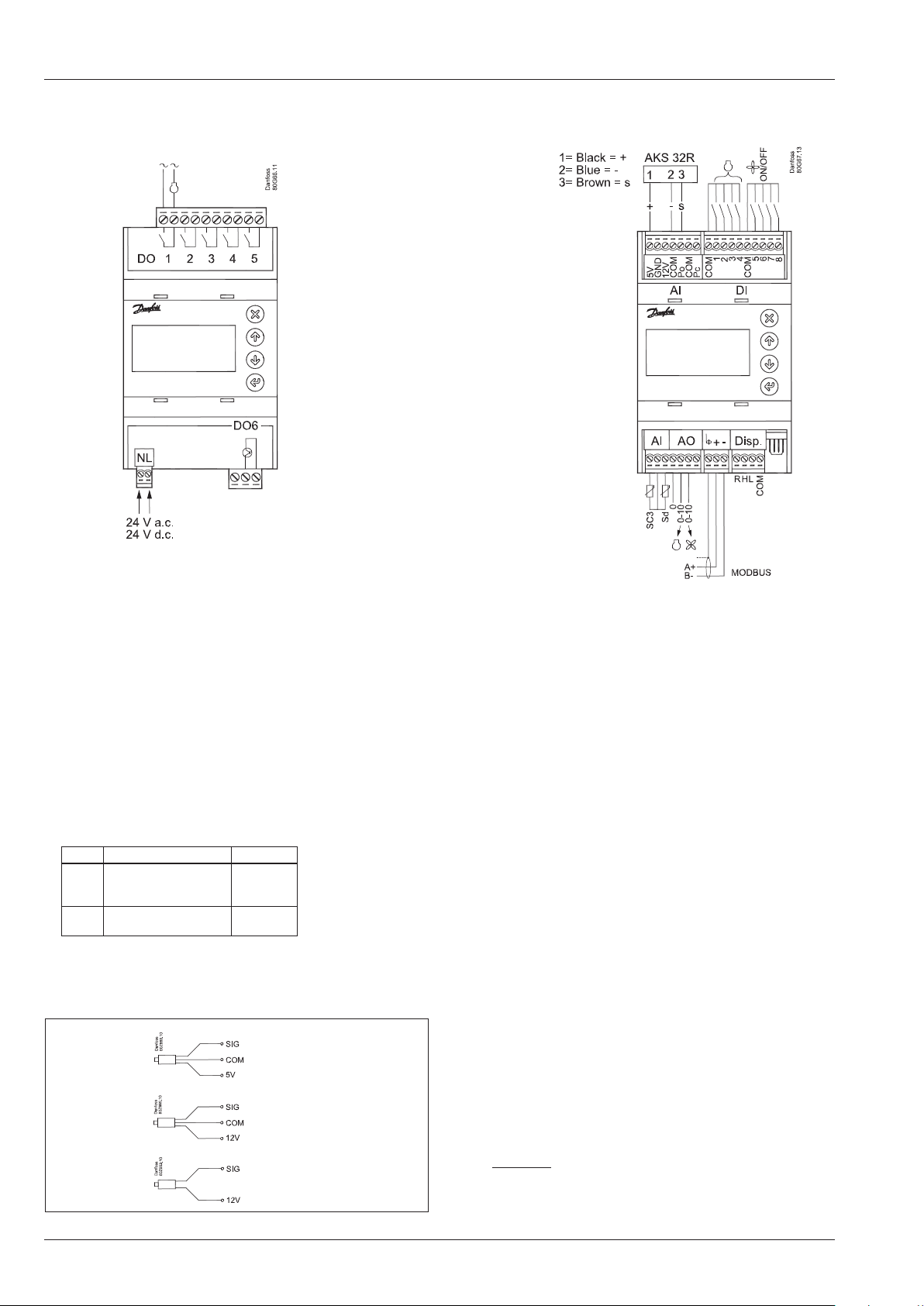
Connection, lower level
All 24 V or
all 230 V a.c.
Connection, upper level
Warning
The supply voltage of AI may
not share the signal with
other controllers.
Supply Voltage
24 V a.c. or 24 V d.c.
DO - Digital outputs, 6 pcs. DO1 - DO6
DO6 is solid state relay.
The relays are de-rated to the specied values.
If an alarm relay is dened, it will be driven under normal operation and it will drop in the event of alarms and insucient
power to the controller.
DO DO1-DO5 DO6
I Max. 5 A
(2)
U All 24 V or
all 230 V a.c.
AKS 32R
AKS 32
AKS 33
0,5 A
min. 50 mA
Io < 1,5 mA
10-90% ratiometric
1-5 V
0-20mA
4-20mA
AI - Analogue inputs, 4 pcs. AI1 - AI4
AI1- Sc3: Pt 1000 ohm, AKS 11 or AKS 21.
AI2 - Sd compressor 1: NTC 86K ohm @ 25°C, from digital scroll
or Pt 1000 ohm
AI3: Presure transmitter Po or temperature sensor S4, Pt 1000
ohm
AI4: Pressure transmitter Pc or temperature sensor S7, Pt 1000
ohm
Pressure transmitters
• Ratiometric: 10-90% of supply, AKS 32R / AKS 2050
• Signal: 1-5 V, AKS 32
• Current: 0-20 mA / 4-20 mA, AKS 33 (supply = 12 V)
DI - Digital switch inputs, 8 pcs. DI1 - DI8
The connection may be a shut-down or interruption function.
Select what is to be activated during conguration.
DI1-4: Safety circuits, compressor 1, 2, 3 and 4
DI5: Safety circuits, condenser fans
DI6: External Main Switch
DI7: Night signal or LP switch
DI8 General alarm or HP switch
AO - Analogue output, 2 pcs. AO1 - AO2
Must be used when using a frequency converter or EC motors.
Obtain 0-10 volts from terminals COM and AO1 (compressor),
respectively COM and AO2 (fans).
Modbus
It is important that the installation of the data communication
cable be done correctly. Cf. separate literature No. RC8AC.
Remember termination at the bus termination.
2 Instructions RI8RB2ML © Danfoss 09/2014 AK-PC 351
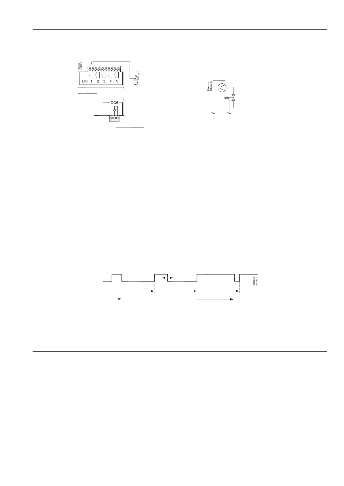
The capacity from the digital scroll compressor
Only DO6
The capacity is divided into period times as "PWM per". 100% capacity is delivered when cooling takes place for the whole period.
An o time is required by the capacity control valve within the period and an on time is also permitted. There is "no cooling" when the
valve is on.
The controller itself calculates the capacity needed and will then vary it according to the cut-in time of the capacity control valve.
A limit is introduced if low capacity is needed so that the cooling does not go below 10%. This is because the compressor can cool
itself. This value can be increased if necessary.
The capacity can similarly be limited so that the compressor cannot deliver 100% capacity. It is not normally necessary to limit this
max. capacity.
Sd monitoring
When regulating with Sd monitoring, the controller will increase capacity if the temperature nears the Sd limit. This will result in better
cooling of the digital scroll compressor.
Refrigeration
No refrigeration
PWM period time
PWM Min. Cycle
PWM Max. Cycle
Stream kompressor
The PWM signal can also be used to control one stream compressor with one relief valve.
The compressor capacity is distributed by up to 50% for one relay and the remaining 50-100% for the unloader. The unloader is connected to DO6.
Sd can be monitored like a scroll compressor.
AK-PC 351 Instructions RI8RB2ML © Danfoss 09/2014 3
Português
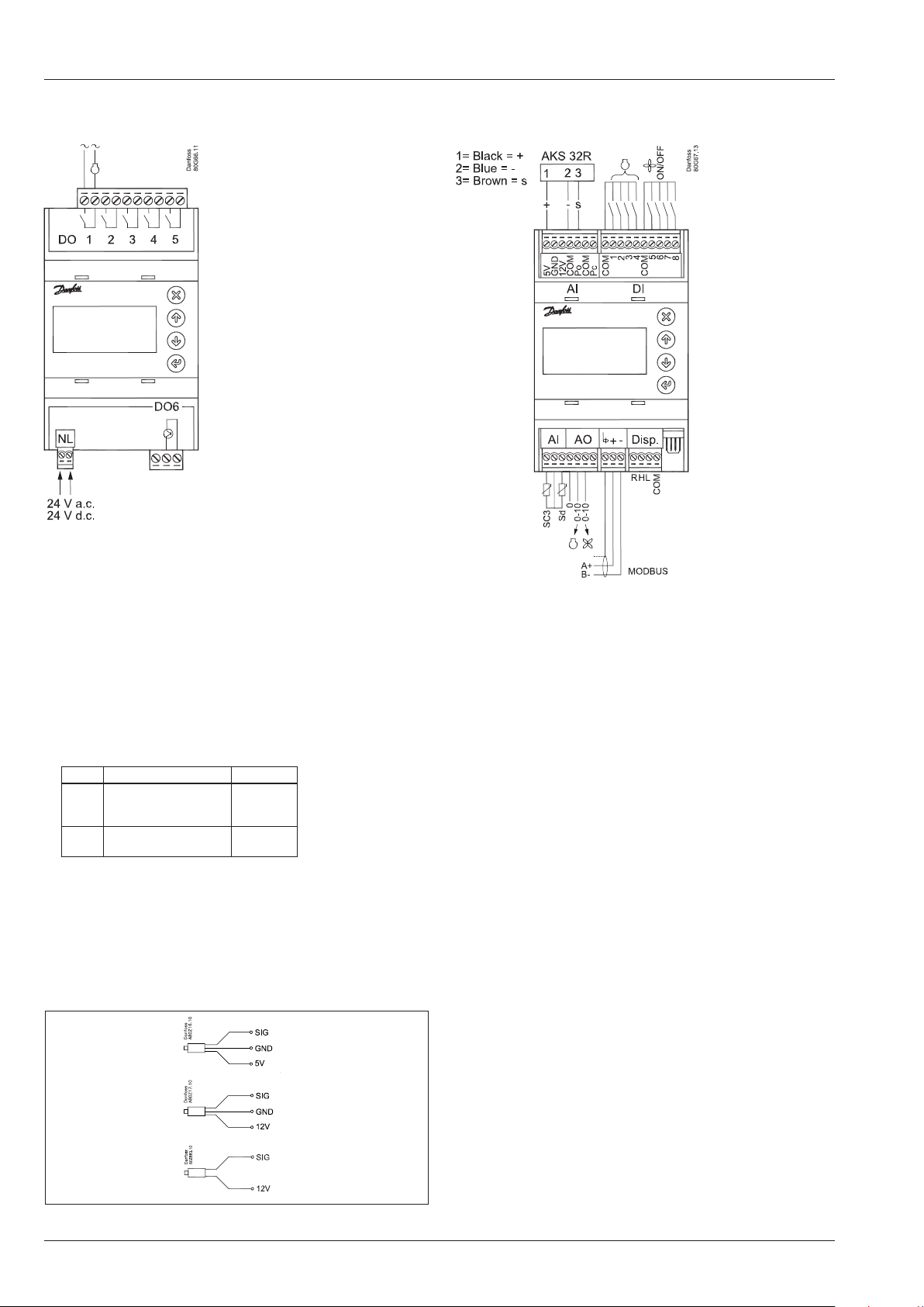
Conexões, nível mais baixo Conexões, nível superior
Todas 24 V ou
todas 230 V c.a.
Advertência
A tensão de alimentação
do AI pode não compartilhar o sinal com outros
controladores.
Fonte de alimentação
24 V c.a. ou 24 V c.c.
DO - saídas digitais, 6 pcs. DO1 - DO6
DO6 são relé de estado sólido.
É feito derate dos relés para os valores especicados.
Caso um relé de alarme seja denido, ele será acionado
durante a operação normal e desarmará em caso de alarmes
e de tensão insuciente para o controlador.
DO DO1-DO5 DO6
I Max. 5 A
(2)
U Todas 24 V ou
todas 230 V CA
AKS 32R
0,5 A
mín. 50 mA
Io < 1,5 mA
10-90% ratiometric
AI - entradas analógicas, 4 pcs. AI1 - AI4
AI1- Sc3: Pt 1000 ohm, AKS 11 ou AKS 21.
AI2 - Sd compressor 1: NTC 86K ohm @ 25°C, a partir de digital
scroll ou Pt 1000 ohm
AI3: Transmissor de pressão Po ou sensor de temperatura S4, Pt
1000 ohm
AI4: Transmissor de pressão Pc ou sensor de temperatura S7, Pt
1000 ohm
Transmissores de pressão
• Ratiometric: 10-90% do fornecimento, AKS 32R / AKS2050
• Sinal: 1-5 V, AKS 32
• fonte de alimentação: 0-20 mA / 4-20 mA, AKS 33 (fornecimento = 12 V)
DI - Entradas digital chave, 8 pcs. DI1 - DI8
A conexão pode ser um desligamento ou função de interrupção.
Selecione o que deverá ser ativado durante a conguração.
DI1-4: Os circuitos de segurança, compressor1, 2, 3 e 4
DI5: Os circuitos de segurança, ventiladores do condensador
DI6:External Interruptor principal
DI7: Sinal Noite ou chave BP
DI8 Alarme geral ou chave AP
AO - saída analógica, 2 pcs. AO1 - AO2
Deverão ser utilizadas ao usar um conversor de frequência ou
motores EC.
Obtenha 0-10 volts dos terminais COM e AO1 (compressor),
respectivamente COM e AO2 (ventilador).
AKS 32
1-5 V
Modbus
É importante que a instalação do cabo de comunicação de
dados seja feita corretamente.
AKS 33
0-20mA
4-20mA
Consulte a literatura separada nº RC8AC…
Lembre-se: terminação na terminação do barramento.
4 Instructions RI8RB2ML © Danfoss 09/2014 AK-PC 351

A capacidade do compressor de rolagem digital
Only DO6
A capacidade é dividida em períodos de tempo como “PWM per”. É fornecida 100% da capacidade quando o resfriamento acontece
durante todo o período. Um tempo desligado é necessário para a válvula de bypass dentro do período e um tempo ligado também é
permitido. Não há “resfriamento” quando a válvula estiver ligada.
O controlador por si próprio calcula a capacidade necessária e então irá variá-la de acordo com o tempo de ligar da válvula de controle
de capacidade.
Um limite é introduzido se uma baixa capacidade for necessária de modo que o resfriamento não caia para baixo de 10%. Isto é porque
o compressor pode resfriar-se a si próprio. Esse valor poderá ser aumentado, se necessário.
De modo análogo, a capacidade pode ser limitada, de maneira que o compressor não possa fornecer 100% da capacidade. Normalmente não é necessário limitar essa capacidade máxima.
Monitoramento Sd
Ao regular com o monitoramento Sd, o controlador irá aumentar a capacidade se a temperatura aproximar do limite Sd. Isso irá resultar
em um melhor resfriamento do compressor de rolagem digital.
Refrigeração
Sem refrigeração
PWM period time
PWM Min. Cycle
PWM Max. Cycle
Compressor de uxo
O sinal de PWM também pode ser usado para controlar um compressor de uxo com uma válvula de descarregador.
A capacidade do compressor é distribuída por até 50% para um relé e os restantes 50-100% para o descarregador.
O descarregador está conectado em DO6.
O Sd pode ser monitorado como um compressor de rolagem.
AK-PC 351 Instructions RI8RB2ML © Danfoss 09/2014 5

The Product contains electrical components
And may not be disposed together with domestic waste.
Equipment must be separate collected with Electrical and Electronic waste. According to Local and currently valid legislation.
6 Instructions RI8RB2ML © Danfoss 09/2014 AK-PC 351
ADAP-KOOL®
 Loading...