

Page 1
Transfer a reference set-up to a controller
When you have created a reference set-up as described on the previous page, you can transfer this set-up to a controller on the system. If the
reference set-up consists of a number of controllers, you can transfer all
simultaneously.
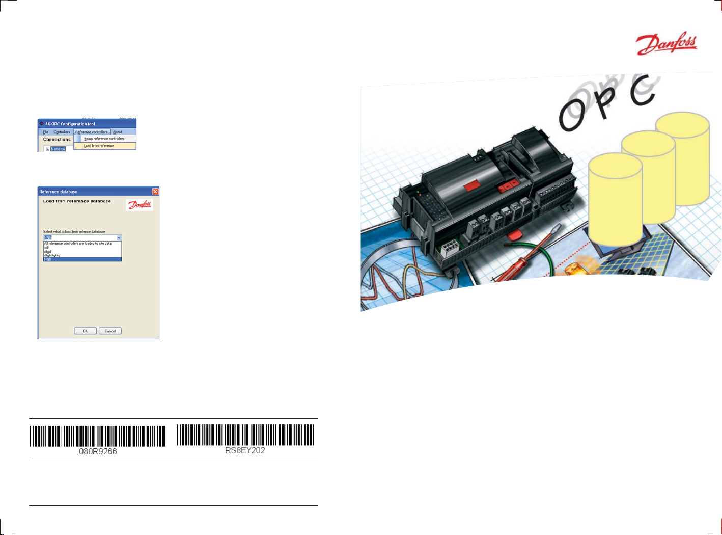
1. Activate the ”Load from reference” function
2. Select fi le
Select the current fi le or select ”All”
on the top line.
3. Press ”OK”
Danfoss can accept no responsibility for possible errors in catalogues, brochures and other printed material.
Danfoss reserves the right to alter its products without notice. This also applies to products already on order
provided that such alternations can be made without subsequential changes being necessary in specifi cations
already agreed.
All trademarks in this material are property of the respecitve companies. Danfoss and Danfoss logotype are
trademarks of Danfoss A/S. All rights reserved.
16
12-2008 RS8EY202
DE-BD
AK-OPC 100 server
Con guration so ware
REFRIGERATION AND
AIR CONDITIONING
Manual
Page 2
Introduction
Reference setup
This programme package contains an OPC-server and setup tools, which
makes it possible to obtain measurements from refrigeration products
regulated by ADAP-KOOL® Refrigeration product management.
You can also make daily adjustments but any confi guration changes must
be made using other tools.
The user interface would be an OPC client.
If you want to do a setup of one of the controller types, so that the setup
creates a template and reference for other controllers, do as follows
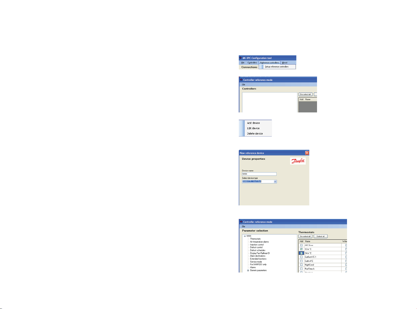
1. Activate reference function
2. Right click on mouse
3. Add device
Give a name
Select description fi le
4. Parameter selection
5. Close Reference setup
2
15
Page 3
Setup continued
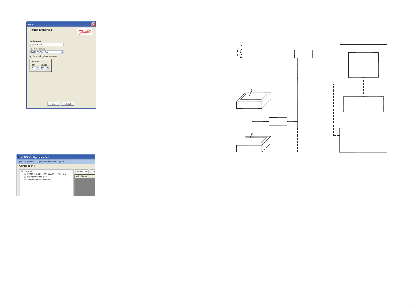
c. Select a controller address and connect it to its description fi le.
Give the controller a name
Princip
Then select the current description
fi le from the list “Select device type”.
If a reference setup has already been
created for this controller and the
controller requires this setup, then it
must be ticked.
Select the controller’s address.
(A system device has 11:1 and a controller will have 1:xxx)
d. Finish with OK
When you have selected the
controller and it has been placed
on the overview display, you can
edit the line by right clicking on the
mouse.
5. Selecting those parameters to be shown to the OPC-client
a. Click on “+” to see controller functions
b. Select a function
c. Tick the required parameters (see menu on page 11)
System unit
PC
AK-OPC
Software
Controller
OPC Client
Controller
PC
SCADA
OPC
AK-OPC software defi nes which measurements are needed.
The PC is connected to the system device on the ADAP-KOOL® system,
which is then connected to individual controllers and their sensors.
During operation, the AK-OPC software will seek out data in the system,
receive sought data and thereafter continue to the next selected
measurement.
6. When you have gone through all the controllers, the installation is
complete.
14
3
Page 4

Before installation
Info
The following is required:
Software package with:
• CD with 2 programmes
- Confi guration programme
- Server programme
• Licence key (for USB port)
• Installation guide (this manual)
Order number for package = 080Z0165.
PC requirements: Pentium 4 PC with serial port and USB access
512 MB RAM, 40 GB Harddisk.
Software requirements: Windows XP sp 2.
Cable: Cable between PC and system device
Order number = 080Z0262.
(The same cable is used for connecting Service tool AK-ST
500 – order number = 080Z0161.)
If a longer cable is required between the controller and
the PC, then a standard RS 232 extension cable can be
used. The distance between the controller and the PC
must not be more than 15 metres.
If you cannot fi nd the description fi le
in the overview, then you can upload it
from the controller.
In order to access the fi le, you will
need to connect the PC to the network
and you need to install the software
programme AK-ST 500 (service tool) on
the PC. When you start the service tool
programme, it will upload all relevant
fi les on the PC and place them in the
cache folder shown.
Next step is to move the fi les from the
overview for selection.
In the overview display, select the function “Load controller descriptions.”
Then copy all fi les from the Cache
folder to the menu display.
Controllers: The programme will connect to controllers on the
network. You can now start to look for controllers on the
network. You will need the order number, software version and network address.
4
Info
If you have two or more controllers of the same type and if it is the same
data that needs to be presented, then you can set up a reference setup with
the required data. All controllers of the same type are thereafter “hooked”
together on this view.
See page 15 for setup of a reference setup.
13
Page 5

3. Select which controller type on the system
Here are all the description fi les available. You
should only select those fi les that correspond with
the controllers on the system. Code number and
software version.
(Only those selected can be seen in the next view)
The fi le comes from the CD, where all current fi les
are stored.
If you cannot fi nd a current fi le for a given controller
on the network, then you can upload it from the list.
See how on page 13.
4. Add a controller to the list
a. Right click on the left fi eld
Setup continued
Info
Description fi les
The CD contains a number of description fi les for all current types of controllers. You can use these fi les when confi guration, as long as your controllers are the same type and have the same version of software.
If you cannot fi nd the fi le on the CD then you can access it from the PC by
connecting the Service tool to the PC. The service tool will upload fetch the
fi le from the controller, giving you access to it.
You can upload a description fi le before or after the installation but it must
be made before the confi guration.
Identical data from several controllers
If you have a series of refrigeration appliances controlled by the same type
of controller and you want access to the same data from all appliances, then
you can create a reference setup. Once the reference setup has been created it becomes easy to connect the controllers. It is also possible to create
more reference setups for a code number + SW version, if needed.
A reference setup must be done prior to confi guration.
Controller Overview
Create an overview of controllers on the network, which can be connected
to the OPC-client.
Example
Code no. Software
version
080Z8511 1.20 11:001 System unit
080Z0111 2.00 1:10 Compressor control
084B6175 1.5x 1:108 Appliance control ....
084B6175 1.5x 1:109 Appliance control ........
084B6175 1.5x 1:110 Appliance control ..........
Network
address
Description
b. Click on “Add device”
Continued on page 14.
12
(Service tool AK-ST 500 can be used to obtain data from the network.)
5
Page 6

How to install the programme
Info
1. Insert CD-Rom in the PC’s drive
2. In the folder “AK-OPC confi guration tool”, select fi le “Setup”.
3. Activate setup fi le
Follow
instructions
4. In the folder “AK-OPC 100 Server install”, select fi le “Setup”.
5. Activate setup fi le
The end result will be a complete picture, where the chosen functions will
be available for later use.
The com port on the PC (the point where the cable is connected to the
system)
System Device
Code number and software version of controller (the
number and version have been changed to a more
meaningful text)
Groups of controller’s diff erent functions
Selectable functions
Only the ticked will be available for
the OPC client.
Continued on page 8.
6
Follow
instructions
11
Page 7

Con guration
Info
The following shows how to select the parameters an OPC-client may be
interested in.
1. Start programme “OPC confi guration”
The menu consists of two main elements:
• The left-hand side, showing connections, controllers and headings.
• The right-hand side showing parameters and where the desired ones
can be selected.
The confi guration programme is used to select current parameters in the
desired operating interface. It is these selected parameters (and only them)
that are handled by the Server programme.
The Server programme will ensure communication of the selected parameters. Communication takes place between selected controllers and the
operating interface with the OPC client.
2. Defi ne connection from the PC
Select COM-port and give
the connection a name
Continued on page 12
10
7
Page 8

Installation continued
6. Next is installation of Licence software
7. Choose the language you would like the installation in
Follow
instructions
8. After installation, select “Close”.
9. Plug the licence key into a USB port in the PC.
10. Plug the cable into the COM port in the PC (make a note of the number
on the COM port. You will need it for later.)
11. Plug the other end of the cable into the socket on the system.
Info
The software on the CD is protected, so that it cannot be used on more PCs
at the same time.
Protection is activated by installing the software and plugging the Licence
key into the USB port on the PC.
If the licence key is removed from the USB port on the PC, then communication between the controllers and the OPC client will cease.
8
9
 Loading...