

Page 1

User Guide
Monitoring unit
AK-LM 330
ADAP-KOOL® Refrigeration control systems
Page 2
Menu list This menu function can be used together with system software type AKM. The description is divided
up into function groups that can be displayed on the PC screen. Within each group it is now possible
to show the measured values, or settings. Regarding the use of AKM, reference is made to the AKM
Manual.
Validity This menu operation (from September 2012) applies to controller type AK-LM 330, code Nos
080Z0170 with programme version 1.4x.
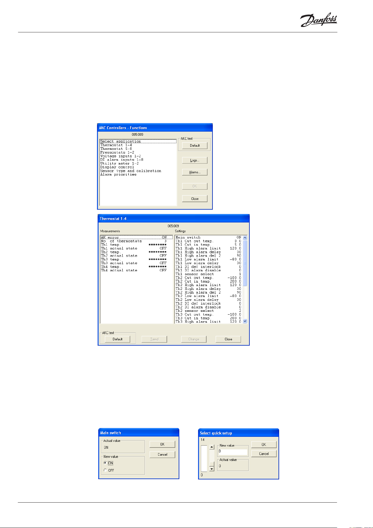
Function groups
The operation is divided up into several
function groups. When a selection has been
made, push “OK”, and you may continue to
the next display. By way of example, "Thermostat 1-4" has been selected here.
From the measure line the dierent values can be read. The values are constantly
updated.
In the list of settings the set values can be
seen. If a setting has to be changed, select
the parameter and proceed via “OK”.
Measurements The various measurements can be read directly. If a graphic display of the measurements is required,
up to eight of them can be shown. Select the required measurements and push “Trend”.
Settings Settings can only be made for the daily operation. Conguration settings cannot be seen, changed or
written out. They can only be made from the Service Tool programme.
There are four kinds of settings, ON/OFF settings, settings with a variable value, time settings and
“reset alarms”.
Set the required value and push “OK”
2 Menu operation RC8CC202 © Danfoss 09/2012 AK-LM 330 Vers. 1.4x
Enter the new value or move the sliding scale up or down.
The new value will apply, when “OK” is pushed.
Page 3
Go through the individual functions one by one and make the required settings. When settings have
been made for one controller, the set values may be used as a basis in the other controllers of the
same type and with the same software version. Copy the settings by using the copy settings function
in the AKM programme, and adjust subsequently any settings where there are deviations.
NB! If a list is required for noting down the individual settings, a printout can be made of it with
a function in the AKM programme. Read the next section, “Documentation”.
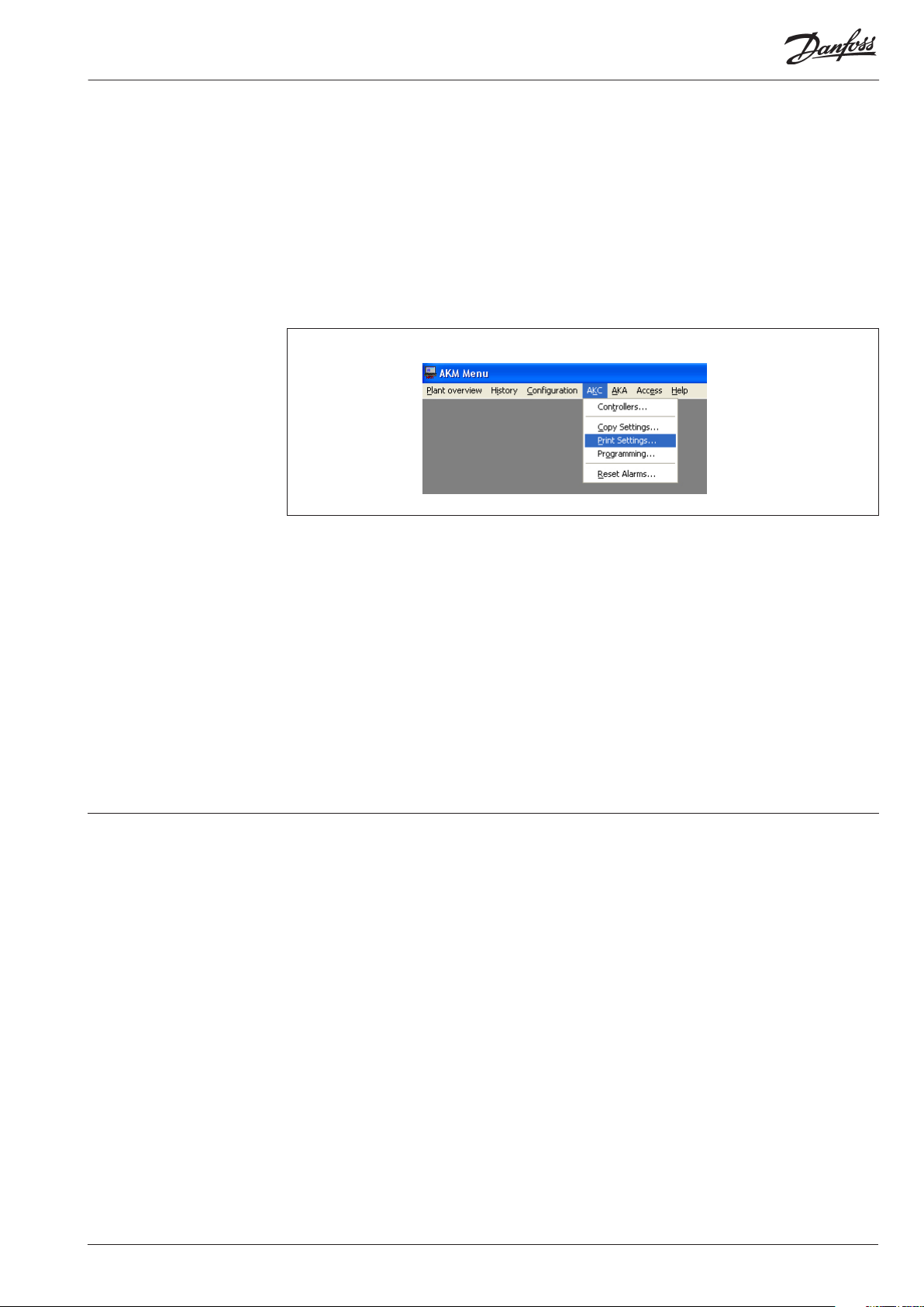
Documentation Documentation of the settings of the individual controllers can be made with the print function in the
AKM programme. Select the controller for which documentation of the settings is required and select
the “Print Settings” function (cf. also the AKM Manual).
Functions Shown below are function groups with corresponding measurements and settings. A printout of the
given settings can be made using the AKM function “Print Settings” (see above).
Note It has been necessary to make a selection from the numerous measurements and settings coming
from the controller.
There is not room for all these in the AKM programme controls.
It can display:
• 8 thermostats
• 2 pressostats
• 2 volt inputs
• 8 digital alarm inputs
• 2 consumption gauges
If it is necessary to obtain access to all measurements and settings, see Using Service Tool, type AK-ST
500.
AK-LM 330 Vers. 1.4x Menu operation RC8CC202 © Danfoss 09/2012 3
Page 4

Select application
Measurements AK error When “ON”, the controller is in alarm condition.
Settings Main switch Main switch: ON: Regulation
OFF: Controller stopped
Conguration lock Locking conguration
To implement changes of certain parameters, the conguration lock must be “open".
Note: “Main switch” must be turned" OFF" to open conguration
0: Open
1: Locked
Select quick setup Selection of predened congurations.
When this is selected, all the controller settings and the denitions of input and out-
put will be adjusted to t the selected application.
(see manual for more details on individual predened settings).
Thermostat 1 - 4
Measurements AK error When “ON”, the controller is in alarm condition.
No. of thermostats The number of thermostats that have been dened can be read here.
1 to 8 can be read and operated in the following menus.
9 or more can only be read and operated from the Service Tool AK-ST
Th1 temp. Temperature Measurements on the sensor dened in "Thermostat 1"
Th 1 actual state The thermostat's actual value is shown here. ON or OFF.
2, 3, 4 There are similar settings for the other thermostats.
Settings Main switch Main switch: ON: Regulation
OFF: Controller stopped
Th1 Cut out temp Cut out value for relay which is dened in "Thermostat 1"
Th1 Cut in temp Cut in value for relay which is dened in "Thermostat 1"
Th1 High alarm limit High alarm limit "Thermostat 1"
Th1 High alarm delay Delay time for high alarm "Thermostat 1" (normal regulation)
Th1 High alarm del 2 Delay time 2 for high alarm "Thermostat 1" (e.g. after a defrost / cooling down)
Th1 Low alarm limit Low alarm limit "Thermostat 1"
Th1 Low alarm delay Delay time for low alarm "Thermostat 1"
Th1 DI def interlock Denition of switch to "Delay time 2" with DI signal
0: not used
1-16: Here, it is dened which DI input is to activate the long delay time.
Th1 DI alarm disable Denition of disarming alarm with DI signal
0: Not used
1-16: Here, the DI input that is to deactivate the alarm function is dened
Th1 Sensor select Here, the sensor that is to be used for "Thermostat 1" is dened
2, 3, 4 There are similar settings for the other thermostats.
Thermostat 5 - 8
Measurements AK error When “ON”, the controller is in alarm condition.
5, 6, 7, 8 Same function as for "Thermostat 1".
Settings Main switch Main switch: ON: Regulation
OFF: Controller stopped
5, 6, 7, 8 Same function as for "Thermostat 1".
4 Menu operation RC8CC202 © Danfoss 09/2012 AK-LM 330 Vers. 1.4x
Page 5

Pressostats 1 - 2
Measurements AK error When “ON”, the controller is in alarm condition.
No. of pressostats The number of pressostats that have been dened can be read here.
1 to 2 can be read and operated in the following menus.
3 or more can only be read and operated from the Service Tool AK-ST 500.
P1 pressure. Pressure reading for the transmitter dened in "Pressostat 1"
P1 actual state The pressostat's actual value is shown here. ON or OFF.
2 There are similar readings for "Pressostat 2".
Settings Main switch Main switch: ON: Regulation
OFF: Controller stopped
P1 Cut out pressure Cut out value for relay "Pressostat 1"
P1 Cut in pressure Cut in value for relay "Pressostat 1"
P1 High alarm limit High alarm limit "Pressostat 1"
P1 High alarm delay Delay time for high alarm "Pressostat 1"
P1 Low alarm limit Low alarm limit "Pressostat 1"
P1 Low alarm delay Delay time for low alarm "Pressostat 1"
P1 Sensor select The transmitter that is to send the signal to "Pressostat 1" is dened here.
2 There are similar settings for "Pressostat 2".
Voltage inputs
Measurements AK error When “ON”, the controller is in alarm condition.
No. of voltage input The number of voltage functions that have been dened can be read here.
1 to 2 can be read and operated in the following menus.
3 or more can only be read and operated from the Service Tool AK-ST 500.
V1 value The voltage measurement for the function dened in "Volt 1"
V1 actual state The function's actual value is shown here. ON or OFF.
2 There are similar readings for "Volt 2".
Settings Main switch Main switch: ON: Regulation
OFF: Controller stopped
V1 Cut out Cut out value for relay which is dened in "Volt 1"
V1 Cut out delay Delay time for cut out of relay
V1 Cut in Cut in value for relay which is dened in "Volt 1"
V1 Cut in delay Delay time for cut in of relay
V1 High alarm limit High alarm limit "Volt 1"
V1 High alarm delay Delay time for high alarm "Volt 1"
V1 Low alarm limit Low alarm limit "Volt 1"
V1 Low alarm delay Delay time for low alarm "Volt 1"
V1 Volt signal type The voltage area that is to send the signal to "Volt 1" is dened here.
0-5 V: Dened with setting = 9
1-5 V: Dened with setting = 11
0-10 V: Dened with setting = 10
2-10 V: Dened with setting = 12
(The received voltage is converted to a value which is dened by the following:
Lower voltage value = Min. read out. Higher voltage value = Max. read out.
It is these limits that form the function's setting values)
V1 Min read out Denition of the reading at the voltage area's lowest value
V1 Max read out Denition of the reading at the voltage area's highest value.
2 There are similar settings for "Volt 2".
AK-LM 330 Vers. 1.4x Menu operation RC8CC202 © Danfoss 09/2012 5
Page 6

DI alarm inputs 1-8
Measurements AK error When “ON”, the controller is in alarm condition.
No of DI input The number of DI inputs that have been dened can be read here.
1 to 8 can be read and operated in the following menus.
9 or more can only be read and operated from the Service Tool AK-ST 500.
DI1 status The signal's actual value for DI1 is shown here. On or O (On = alarm)
DI1 No. of cycles/24h The number of signals that have been changed to "On" within the last 24 hours can
be read here.
DI1 On time/24h The amount of time during which the signal has been "On" within the last 24 hours
(shown in %) can be read here.
2, 3, 4, 5, 6, 7,8 There are similar readings for the other DI inputs.
Settings Main switch Main switch: ON: Regulation
OFF: Controller stopped
DI1 alarm fct. When "On", the DI1 alarm function is active.
DI1 alarm delay Delay time for alarm "DI 1"
DI1 Input polarity The input signal's normal situation and alarm situation is dened here
On: Alarm, when the signal to the input is connected (short circuit/volt supply)
O: Alarm, when the signal to the input is cut o
DI1 Total no. of cyc. Readings for the total number of changes to "On". The value can be reset
DI1 Total ON time Readings for total On time. The value can be reset
2, 3, 4, 5, 6, 7,8 There are similar settings for the other DI inputs.
Utility meter 1-2
Measurements AK error When “ON”, the controller is in alarm condition.
No. of util meters Here, it is possible to read how many power reading functions have been dened.
1 to 2 can be read and operated in the following menus.
3 or more can only be read and operated from the Service Tool AK-ST 500.
UM1 Total consump. Readings for the total consumption registered by "Utility Meter 1"
UM1 Today consump. Readings for today's consumption registered by "Utility Meter 1"
UM1 Last week cons. Readings for last week's consumption registered by "Utility Meter 1"
UM1 Actual load Readings for actual load registered by "Utility Meter 1"
UM1 Average load Readings for average load registered by "Utility Meter 1"
2 There are similar readings for "Utility Meter 2".
Settings Main switch Main switch: ON: Regulation
OFF: Controller stopped
Load period Set period time for synchronising pulses
UM1 Start The measurements can be started and stopped here.
UM1 Pulses/unit Dene how many pulses are to be received for each unit of measure
UM1 Scale factor Set scale factor, if required
UM1 Preset counter The counter can be reset here.
2 There are similar settings for "Utility Meter 2".
6 Menu operation RC8CC202 © Danfoss 09/2012 AK-LM 330 Vers. 1.4x
Page 7

Display control
Measurements AK error When “ON”, the controller is in alarm condition.
Settings Main switch Main switch: ON: Regulation
OFF: Controller stopped
Display control A Set what should be read in "Display A"
Display control B Set what should be read in "Display B"
Display control C Set what should be read in "Display C"
Display control D Set what should be read in "Display D"
No reading = 0
"Thermostat 1" to be dened with setting = 1
"Thermostat 2" to be dened with setting = 2
"Thermostat 3" to be dened with setting = 3
"Thermostat 4" to be dened with setting = 4
"Thermostat 5" to be dened with setting = 5
"Thermostat 6" to be dened with setting = 6
"Thermostat 7" to be dened with setting = 7
"Thermostat 8" to be dened with setting = 8
"Thermostat 9" to be dened with setting = 9
"Thermostat 10" to be dened with setting = 10
"Pressostat 1" to be dened with setting = 11
"Pressostat 2" to be dened with setting = 12
"Pressostat 3" to be dened with setting = 13
"Pressostat 4" to be dened with setting = 14
"Pressostat 5" to be dened with setting = 15
"DI1 Alarm" to be dened with setting = 16
"DI2 Alarm" to be dened with setting = 17
"DI3 Alarm" to be dened with setting = 18
"DI4 Alarm" to be dened with setting = 19
"DI5 Alarm" to be dened with setting = 20
"DI6 Alarm" to be dened with setting = 21
"DI7 Alarm" to be dened with setting = 22
"DI8 Alarm" to be dened with setting = 23
"DI9 Alarm" to be dened with setting = 24
"DI10 Alarm" to be dened with setting = 25
"DI11 Alarm" to be dened with setting = 26
"DI12 Alarm" to be dened with setting = 27
"DI13 Alarm" to be dened with setting = 28
"DI14 Alarm" to be dened with setting = 29
"DI15 Alarm" to be dened with setting = 30
"DI16 Alarm" to be dened with setting = 31
Sensor type and calibration
Measurements AK error When “ON”, the controller is in alarm condition.
Settings Main switch Main switch: ON: Regulation
OFF: Controller stopped
Saux 1 oset Correction of the signal from the sensor "Saux 1" if necessary
2,3,4,5,6,7,8 Do for Saux 2,3,4,5,6,7,8
Paux 1 oset Correction of the signal from the pressure transmitter "Paux 1" if necessary
Paux 2 oset Correction of the signal from the pressure transmitter "Paux 2" if necessary
Saux 1 sensor type Denition of the sensor type for the input "Saux 1"
Pt 1000 ohm dened with setting = 0
PTC 1000 ohm dened with setting = 2
2,3,4,5,6,7,8 Do for Saux 2,3,4,5,6,7,8
Paux 1 sensor type Denition of pressure transmitter type and pressure area for "Paux 1"
AKS 32 -6 dened with setting = 1
AKS 32 -9 dened with setting = 4
AKS 32 -12 dened with setting = 7
AK-LM 330 Vers. 1.4x Menu operation RC8CC202 © Danfoss 09/2012 7
Page 8

AKS 32 -20 dened with setting = 10
AKS 32 -34 dened with setting = 13
AKS 32 -50 dened with setting = 16
AKS 32R -6 dened with setting = 2
AKS 32R -9 dened with setting = 5
AKS 32R -12 dened with setting = 8
AKS 32R -20 dened with setting = 11
AKS 32R -34 dened with setting = 14
AKS 32R - 50 dened with setting = 17
AKS 2050 -59 dened with setting = 31
AKS 2050 -99 dened with setting = 32
AKS 2050 -159 dened with setting = 33
User-dened dened with setting = 0. + settings via Service Tool.
2 Do for Paux 2.
Alarm priorities
Measurements AK error When “ON”, the controller is in alarm condition.
Settings Main switch Main switch: ON: Regulation
OFF: Controller stopped
The alarm priority of the following alarms can be changed:
High priority is dened with setting = 1
Medium priority is dened with setting = 2
Low priority is dened with setting = 3
Overriding the alarms is dened with setting = 0
Stand by mode (Interrupted regulation) See the above introduction
Saux 1 error See the above introduction
2,3,4,5,6,7,8 As for Saux 1
Paux 1 error See the above introduction
2,3,4,5,6,7,8 As for Paux 1
DI1 See the above introduction
2,3,4,5,6,7,8 As for DI1
Th.1 High alarm See the above introduction
Th 1 Low alarm See the above introduction
2,3,4,5,6,7,8 As for Th. 1
P1 Low alarm See the above introduction
P1 High alarm See the above introduction
2 As for P1
V1 High alarm See the above introduction
V1 Low alarm See the above introduction
2 As for V1
Danfoss can accept no responsibility for possible errors in catalogues, brochures and other printed material. Danfoss reserves the right to alter its products without notice. This also applies to products
already on order provided that such alternations can be made without subsequential changes being necessary in specications already agreed.
All trademarks in this material are property of the respecitve companies. Danfoss and Danfoss logotype are trademarks of Danfoss A/S. All rights reserved.
8 Menu operation RC8CC202 © Danfoss 09/2012 AK-LM 330 Vers. 1.4x
DE-DB
 Loading...