

Page 1

User guide
Controller tray for refrigeration
appliance controller with signal
from external controller
AK-CT 200A + AK-CT 201A
ADAP-KOOL® Refrigeration control systems
Page 2
Introduction
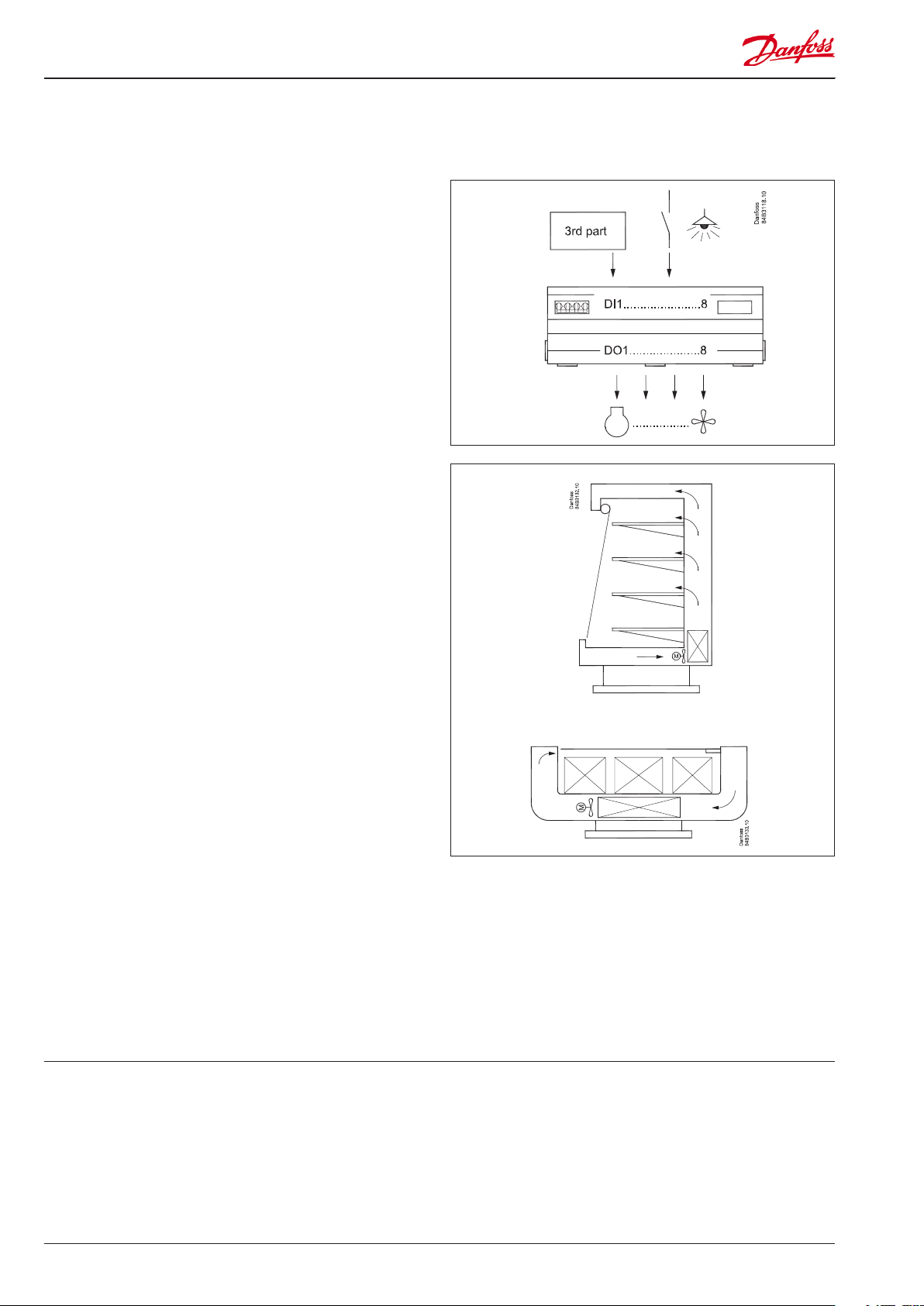
Application
The controller is a complete auxiliary relay module with great
exibility for adaptation of signals from an external controller.
The controller is optimised for connection of loads on
refrigeration appliances and cold rooms, as well as for
controlling the light and night blind.
Advantages
• Optimised for installation by manufacturer
• Electricity-controlled and voltage controlled relay connections
• Loads requiring electricity can be connected directly
• One controller for several dierent refrigeration appliances
• Quick set-up with predened settings
• Built-in data communication
Principle
There are 8 digital inputs, all of which can be dened to connect
to the 8 outlet relays. The relays are controlled by an internal
measurement circuit that ensures an optimum connection time
on the sine curve. The optimum time allows connections to be
made with loads of up to 16 A on individual relays.
The current through each relay will be measured continuously,
and if it becomes higher than the set permissible value, the relay
will cut out and an alarm will be issued.
Functions
- Relays controlled by an external controller, e.g.:
• Compressor and possibly compressor 2
• Defrosting with 1, 2 or 3 phases
• Rail heat
• Fans and fans in eco-operation
• Light and possibly extra lighting
• Night blind
- AK-CT 200A has an alarm relay that is activated for alarms issued
as the result of the cut-out of a relay due to excess current.
Contents
Introduction ....................................................................................................... 2
Operation ............................................................................................................ 4
Applications ....................................................................................................... 6
Connections ....................................................................................................... 9
Survey of functions ........................................................................................ 11
Operation .......................................................................................................... 14
Menu survey .....................................................................................................15
Data ..................................................................................................................... 18
Ordering ............................................................................................................19
2 User Guide RS8GT502 © Danfoss 2016-10 AK-CT 201A
Page 3

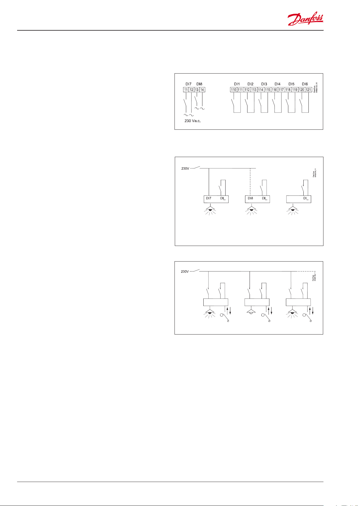
Applications
The controller can connect functions to dierent refrigeration
appliances, such as:
• Standard appliances or cold rooms with one evaporator and
one cooling section.
• Refrigeration appliances with two evaporators and
two cooling sections.
• Refrigeration appliances with one evaporator and
two cooling sections.
The external controller determines which functions are
to be engaged.
A setting will congure the inputs and outputs, so that one input
is destined for a specic relay output.
Installation benets
The controller is designed to provide a number of advantages
when installed by the refrigeration appliance manufacturer,
such as:
High relay load
Load connection/disconnection is controlled by a voltage
measurement and a current measurement, so that the relay’s
switch function can operate under optimal conditions.
The controller can then connect loads of up to 16 A, without
the use of auxiliary relays.
Spring clamps
All cable connections are made using plugs with spring switches.
This allows for fast and easy installation.
Parallel power point
Several of the outlets have double or triple connections points, so
the use of external loop clips is not usually necessary.
Structure of the controller
The controller consists of hardware type AK-CT 200A and a
software identity code AK-CT 201A.
This software identity code is delivered in a separate plug
and must be placed in an RJ45 plug in the hardware. It is rst
necessary to mount the plug when conguring the controller.
AK-CT 201A User Guide RS8GT502 © Danfoss 2016-10 3
Page 4
Operation
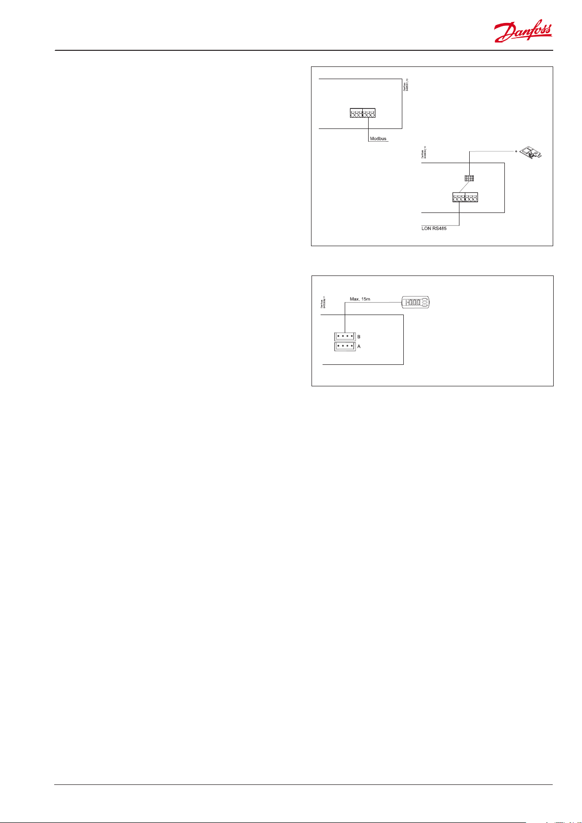
Digital inputs
There are six digital inputs with contact function and two digital
inputs with high voltage signal.
They can be used for the following functions:
• Receive signals from an external controller and then activate
the associated relay.
• Receive signals from switches for the activation of light and
night blind.
Light function
The function can be used for controlling the light in a refrigeration
appliance or in a cold room.
The light function can be dened in two ways:
• The light is controlled by a DI input
• Two signals, both of which can be on before the light goes on.
One can be a DI contact signal at the appliance (fx DI3) and the
other can be a voltage signal on DI7.
Extra light (light 2)
Light 2 can also be activated by one DI input, e.g. DI4.
It can also be controlled with two signals. For two signals,
the second signal must be sent with a voltage signal on DI8.
Night blind
Motorised night blind can be controlled automatically from the
controller. The night blinds will follow the status of the light
function. When the light is switched on, the night blinds opens
and when the light is switched o, the night blinds close again.
When the night blinds are closed, it is possible to open them using
a pulse signal on the digital input. If this input is activated, the
night blinds will open and the refrigeration appliance can be lled
with new products.
If the input is activated again, the blinds close again.
If the activation is omitted, the blind will close automatically when
the delay time expires. A setting is used to dene whether the
light is to be on or o when the night blind is up.
This pulse signal must be connected to one of the following
inputs: DI5, DI7 or DI8.
DI7 DI3
Light 1
controlled by
DI7
and fx DI3.
Light 2
(extra light)
controlled by
DI8 and fx DI4.
Override of light 1
4 User Guide RS8GT502 © Danfoss 2016-10 AK-CT 201A
Page 5
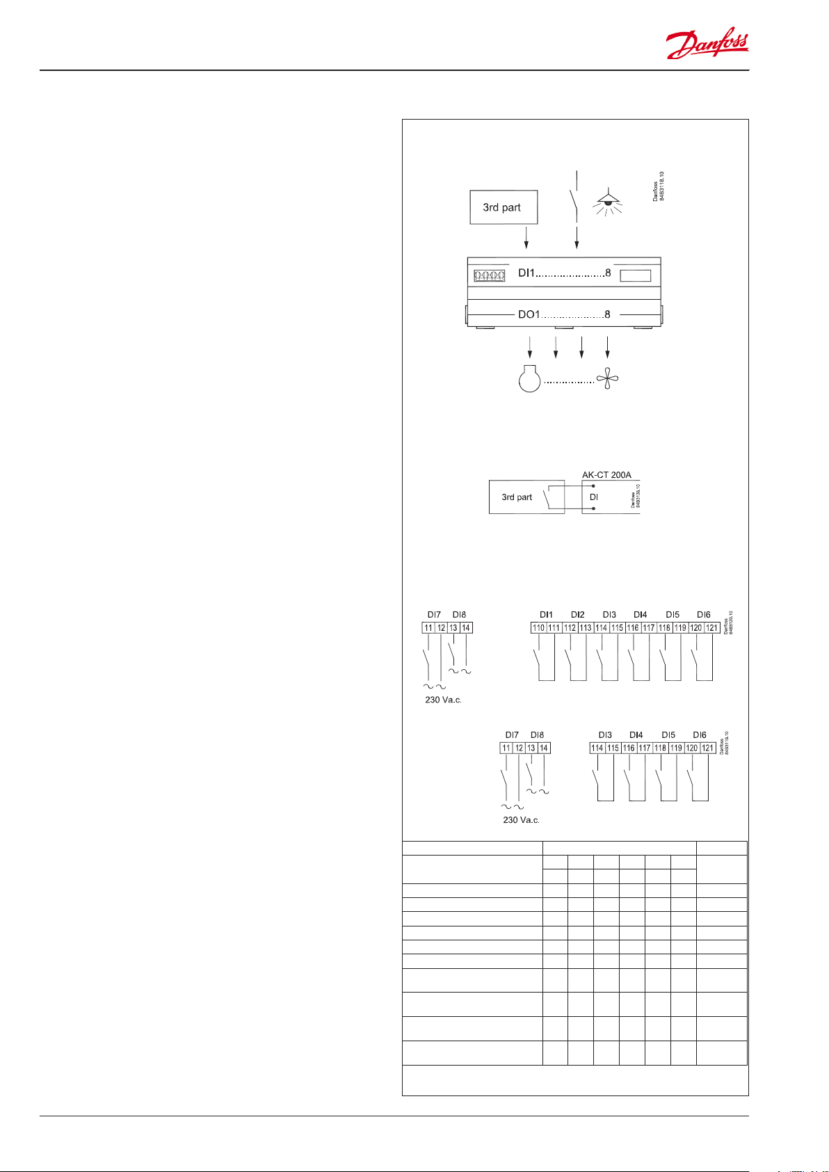
Data communication
The controller has xed built-in MODBUS data communication.
It can be connected to a Danfoss system unit, if required.
If there is a requirement for a dierent form of data
communication, a Lon RS 485 module can be inserted in the
controller.
The connection must then be to terminal RS 485.
(To use a Lon RS 485 module and gateway type AKA 245 the
module must be Version 6.20 or higher.)
Important
All connections to the data communication MODBUS and RS 485
must comply with the requirements for data communication
cables. See literature: RC8AC.
Display
The controller has two plugs for a display. Here display type EKA
163B or EKA 164B (max. length 15m) can be connected.
EKA 163B is a display for readings.
EKA 164B is both for readings and operation.
During standard operation the display will read “ON”.
If one of the relays cuts out due to overcurrent, three LEDs will
ash on the display. In this situation, you can access the alarm list
on the display by pressing the top button.
It is possible to connect two
displays. There are identical
signals on both plugs.
AK-CT 201A User Guide RS8GT502 © Danfoss 2016-10 5
Page 6
Applications
Here is a survey of the controller’s eld of application.
The applications are all adapted for commercial refrigeration
systems in the form of either refrigeration appliances or cold
storage rooms.
Eight connection diagrams are shown on the following pages.
We recommend using the connection diagram that comes
closest to the application. This will result in the greatest degree
of equalisation in the three phases.
Some functions are permanently bound to certain outputs.
In this case, the connection diagram must be followed. The
functions are:
• Defrosting. Here is one or more of the DO outputs used, depending whether the application is a one, two or three-phase
defrosting.
• Fan stop, when the night blind is down. In this case, DO7 is
disconnected.
• Fan ECO function. DO8 is engaged.
Outputs
There are 8 inputs and 8 outputs. Each output can be engaged
by any input, which receives a signal from an external controller
or other switch function.
Alarm output
The alarm relay will be released when the controller registers an
error, e.g. when a relay is disconnected due to excess current.
Digital input
DI1 to DI6 is the on/o input that can be used, for example, for
one of the following functions: activate a relay for e.g. compressor,
defrosting, fan, light, cancel defrost, etc.
DI7 and DI8 are 230 V inputs that can activate similar functions.
See the functions in the respective settings o84, etc.
There are limitations on DO1 and DO2. They can only be used for
signals from the external controller.
Control of night blinds
Night blinds follow the status of the light function – when the
light is switched on, the night blinds are up and when the light is
switched o, the night blinds are down. In addition a digital input
provides the option of forced opening of the blinds so that the
appliance can be lled with products.
Conguration
Function Input/Settings menu Setting
DI3 DI4 DI5 DI6 DI7 DI8
o84 P55 P56 P57 P58 P59
Not used + + + + + + 0
Night blind + + + + + + 12
Light + + + + + + 16
Extra light + + + + + + 17
No defrost + + + + + + 18
Override light + + + + + + 19
Central + decentral
light override
Central + decentral
override of extra light
Central + decentral override of night
blind + on light
Central + decentral override of night
blind, but without light
Example
If DI3 is used to activate a night blind, o84 must be set to 12.
16 16
17 17
12 12 +o38 = 5
12 12 +o38 = 6
6 User Guide RS8GT502 © Danfoss 2016-10 AK-CT 201A
Page 7

1
Danfoss
3
Danfoss
Danfoss
3
Danfoss
One cooling section - one evaporator
2
One cooling section - one evaporator
3-phase defrost
84B3124.1
400V 3N AC
84B3125.13
400V 3N AC
3
84B3126.1
400V 3N AC
Two cooling sections - two evaporators
2-phase defrost
4
84B3127.13
400V 3N AC
Two cooling sections - two evaporators
3-phase defrost
AK-CT 201A User Guide RS8GT502 © Danfoss 2016-10 7
Page 8

5
Danfoss
Danfoss
3
Danfoss
Danfoss
3
Two cooling sections - one evaporator
6
Two cooling sections - one evaporator
3-phase defrost
84B3128.1
400V 3N AC
84B3129.13
400V 3N AC
7
Hot gas defrosting
With relays for:
Main valve in suction line
Hot gas valve
Drainage valve
8
”Two-compressor” operation
84B3130.1
400V 3N AC
84B3131.13
400V 3N AC
8 User Guide RS8GT502 © Danfoss 2016-10 AK-CT 201A
Page 9

Connections
Supply voltage
230 V, or 2 phases + neutral, or 3 phases + neutral. 50 Hz.
Neutral must be tted. If neutral is not in place, the controller can
be damaged. During assembly and disassembly, the power supply
must be interrupted).
DO1 - DO8
If the functions “Defrosting”, “Fan stop” or “Fan ECO” are used,
internal functions will connect to the aected outputs. The
connection will be performed as shown in the diagram.
Otherwise, the connection will, in principle, be optional;
however, with regard to the connection diagram, the following
is recommended:
DO1
Cooling or suction line valve
DO2
Defrost cycle or hot gas valve
DO3
Light
DO4
Light 2, compressor 2 or heating element in drip tray
Pressure transmitter
Not used
AO1
Not usedDI1-DI6
Digital input signal.
The dened function is active when the input is closed/opened.
DI7-DI8
Digital input signal.
The dened function is active when the input receives 230 V.
Data communication
If data communication is used, it is important that the installation
of the data communication cable is performed correctly.
See separate literature No. RC8AC…
MODBUS
For data communication.
Terminal 133 = BTerminal 134 = A+
Terminal 135 = screen
RS485 (terminal 130, 131,132)
For data communication, but only if a data communication
module is inserted in the controller. The module can be a LON
RS485.
Terminal 130 = B (B-)
Terminal 131 = A (A+)
Terminal 132 = screen
DO5
Night blind or defrost cycle 2
DO6
Rail heat
DO7
Fan
DO8
Fan in economy mode or defrost 3 or drain valve
Conguration
Relay output DO1 DO2 DO3 DO4 DO5 DO6 DO7 DO8
Menu L41 L42 L43 L44 L45 L46 L47 L48
Setting
The relay output must
not be used
DI input that will activate
the output
0 0 0 0 0 0 0 0
1 - 8 1 - 8 1 - 8 1 - 8 1 - 8 1 - 8 1 - 8 1 - 8
DO9
Alarm
There is a connection between terminal 100 and 101 in an alarm
situation, as well as when the controller is without voltage.
DOA
Not used
S2 ... S6B
The sensor input is not used
(For LON RS485 and gateway type AKA 245 the gateway must be
version 6.20 or higher.)
EKA Display
If there is be external reading/operation of the controller, display
type EKA 163B or EKA 164B can be connected.
Electric noise
Cables for sensors, DI inputs and data communication must be
kept separate from other electric cables:
- Use separate cable trays
- Keep a distance between cables of at least 10 cm
- Long cables at the DI input should be avoided.
Installation considerations
Accidental damage, poor installation, or site conditions, can give
rise to malfunctions of the control system, and ultimately lead to a
plant breakdown.
Every possible safeguard is incorporated into our products to
prevent this. However, a wrong installation, for example, could still
present problems. Electronic controls are no substitute for normal,
good engineering practice.
Danfoss will not be responsible for any goods, or plant components, damaged as a result of the above defects. It is the installer's
responsibility to check the installation thoroughly, and to t the
necessary safety devices.
Special reference is made to the necessity of signals to the
controller when the compressor is stopped and to the need of
liquid receivers before the compressors.
Your local Danfoss agent will be pleased to assist with further
advice, etc.
AK-CT 201A User Guide RS8GT502 © Danfoss 2016-10 9
Page 10

Extra connection/terminal strip
There are 3 holes on the base in which
a terminal strip (type Wago 862-8593)
can be mounted.
There are holes for 2 terminal strips.
ID-module AK-CT 201A
This module contains a code which release a
regulation with a extern controller.
The installation and removal of the module must always be
performed while the appliance is voltage-free.
Stripping wire
The following demands for stripping, so the insulation does not
enter the spring clip.
When the module is inserted in the plug, the controller can be set.
The settings will be saved in both the controller and the module.
A module with settings will always overwrite the settings in
the controller. An overwrite will be nished 3 seconds after the
controller is turned on.
The module can be removed from the controller for a short period
of time in order to transfer the settings to another, corresponding
controller. Remember to disconnect the voltage to ensure the
system is voltage-free.
If the controller registers a missing module, an alarm will be
issued. This alarm will be regularly repeated until the module is
inserted in the controller again.
If the controller is without a module for a longer period of time
(several days), the regulation will stop and all outputs are reset.
If it becomes necessary to erase all settings from the module, it
can be inserted into the controller and setting P61 can then be activated. Then remove the module without restarting the controller.
A factory-new or “empty” module can be used to retrieve settings
based on a corresponding controller.
Insert the module into the controller from which the settings are
to be retrieved.
Turn on voltage.
Wait 3 seconds. Turn o again.
The module now contains all settings — including the Modbus
address.
Remember to change the address when the module has been
inserted into the receiving apparatus.
10 User Guide RS8GT502 © Danfoss 2016-10 AK-CT 201A
Page 11

Survey of functions
Function Para-
meter
Normal display
The normal display reads “ON” to indicate regulation.
Start / stop of regulation
With this setting refrigeration can be started, stopped or a manual override of the
outputs can be allowed. (For manual control the value is set at -1. Then the relay
outlets can be force-controlled by the respective reading parameters (u23, u58, etc.).
Here the read value can be overwritten.) Refer also to the menu overview on page 15.
Stopped regulation will give a ”Standby alarm”.
Electricity monitoring
Current amount of electricity through relay 1 L11 DO1 Amp
Same for relays 2-8 L12-18 DO2 Amp......DO8 Amp
Fuse status for relay circuit 1, O=interrupted, On=ok.
An interrupted fuse must be re-established with the setting = “On”
Same for relays 2-8 L22-28 DO2 Fuse...... DO8 Fuse
Set the electricity value at which the relay should cut out in the event of overcurrent.
Recommended setting = measured consumption +25%. (When setting = 0 current
monitoring will be cancelled.)
Same for relays 2-8 L32-38 DO2 FuseSize...... DO8 FuseSize
Setting for relay DO1. Here the user can set the DI input that causes DO1 to engage. L41 DO1 wired DI
Same for relays 2-8 L42-48 DO2 wired DI........ DO8 wired DI
Current voltage on phase F1 L51 L1 voltage
Current voltage on phase F2 L52 L2 voltage
Current voltage on phase F3 L53 L3 voltage
Alarm limit for low DO2 load. (not application 7)
An alarm is issued if the electricity consumption becomes lower than the set value.
Alarm limit for low DO5 load (Application 2, 4 and 6 only) L65 DO5 Low Load
Alarm limit for low DO6 load L66 DO6 Low Load
Alarm limit for low DO8 load (Application 2, 3, 4 and 6 only) L68 DO8 Low Load
Miscellaneous Miscellaneous
Delay of output signal after start-up
After start-up or a power failure the controller’s functions can be delayed so that
overloading of the electricity supply network is avoided.
Here you can set the time delay.
If the controller is built into a network with data communication, it must have an
address, and the master gateway of the data communication must then know this
address.
Parameter by operation via data
communication
r12 Main Switch
1: Start
0: Stop
-1: Manual control of outputs permitted
L21 DO1 Fuse
L31 DO1 FuseSize
L62 DO2 Low Load
o01 DelayOfOutp.
The address is set between 0 and 240, depending on the system unit and the selected
data communication. If the system unit is gateway type AKA 245, the version must be
6.20 or higher.
The address is sent to the gateway when the menu is set in pos. ON
IMPORTANT: Before you set o04, you MUST set o61. Otherwise you will be
transmitting incorrect data.
(The function is not used when the data communication is MODBUS)
Access code 1 (Access to all settings)
If the settings in the controller are to be protected with an access code you can set a
numerical value between 0 and 100. If not, you can cancel the function with setting 0.
(99 will always give you access).
Conguration of light function
5) Light controlled with local DI switch and a central 230 V signal on DI7. Both must
be on before the light is turned on.
(If night blind is selected, it will be synchronised with the light function)
6) Like “5”, but the light will follow a manual control of the night blind.
(1-4 Not used)
Selection of application
The controller can be dened in various ways. Here you set which of the
8 applications is required. On page 7 to 8 you can see a survey of applications.
This menu can only be set when regulation is stopped, i.e. “r12” is set to 0.
AK-CT 201A User Guide RS8GT502 © Danfoss 2016-10 11
o03
o04
o05 Acc. code
o38 Light cong
o61 Appl. Mode
Page 12

Access code 2 (Access to adjustments)
There is access to adjustments of values, but not to conguration settings. If the
settings in the controller are to be protected with an access code you can set a
numerical value between 0 and 100. If not, you can cancel the function with setting 0.
If the function is used, access code 1 (o05) must also be used.
Save as factory setting
With this setting you save the controller’s actual settings as a new basic setting
(the earlier factory settings are overwritten).
Digital input signal - DI3 Switch signal
The controller has a digital input 3 which can be used for one of the following
functions:
O: The input is not used.
Setting 1-11 is not used
12) Night blind. Pulse signal activates night blind
13) Not used
14-15 ) Not used
16) Light. Light function when there are signals on both DI3 and DI7.
17) Extra light. Light function when there are signals on both DI4 and DI8.
18) Cancel defrost cycle. All defrost cycles are cancelled when the input is closed.
19) Override light on appliance without night blind (pulse signal).
Digital input signal - DI4. Switch signal. See DI3 above P55 DI4 cong.
Digital input signal - DI5. Switch signal. See DI3 above P56 DI5 cong.
Digital input signal - DI6. Switch signal. See DI3 above P57 DI6 cong.
Digital input signal - DI7. High voltage signal. Functions the same as those
for DI3, but signal is 0 V/230 V. See also the summary on page 6.
Digital input signal - DI8. High voltage signal. See DI7 above P59 DI8 cong.
Max. opening time for night blind after manual DI activation
The delay time before the night blind automatically goes down again after being
manually opened for product stocking.
Reset settings on ID module
Reset all settings so that the ID module can receive settings from another controller.
Conguration of night blind function
On= night blind function used. O=night blind function not used.
Fan pause while night blind rolls down
Here you can set the fan pause time, so the night blind can roll down unhindered
to the correct position.
Max. on time for light after manual DI activation
Delay time before light goes o again following light is on manually due to product
stocking.
Service Service
Status on DI1 input. on/1=closed u10 DI1 status
Status on DI2 input. on/1=closed u37 DI2 status
* Status on relay for cooling u58 Comp1/LLSV
* Status on relay for fan u59 Fan relay
* Status on relay for defrost u60 Def. relay
* Status on relay for railheat u61 Railh. relay
Status on relay for alarm u62 Alarm relay
Status on relay for light u63 Light relay
* Status on relay for hot gas valve u64 SuctionValve
* Status on relay for compressor 2 u67 Comp2 relay
* Status on relay for hot gas
* Status on relay for heating element in drip tray
* Status on relay for night blinds
* Status on relay for defrost 2
Status on input DI3 (closed / open)
* Status of relay for light 2 U36 Extra light
* Status of relay for ECO fan U37 Fan Eco
* Status on relay for defrost 3 U38 Def. relay 3
Status of DI4 input. On=closed U39 DI4 status
Status of DI5 input. On=closed U40 DI5 status
Status of DI6 input. On=closed U41 DI6 status
Status of high-voltage input DI7 U42 DI7 status
Status of high voltage input DI8 U43 DI8 status
o64 Acc. code 2
o67 -
o84 DI3 cong.
P58 DI7 cong.
P60 BlindOpenTim
P61 ResetID Mem.
P64 Blind cong
P65 BlindFanStop
P66 Light On Time
u80 Hotgas valve
u81 Drip tray
u82 Blinds relay
u83 Def. relay 2
u87 DI3 status
12 User Guide RS8GT502 © Danfoss 2016-10 AK-CT 201A
Page 13

Modbus communication status, 0% = none; 100% = everything ok U45 Comm. status
* Status on relay for drain valve 1=on U55 Drain valve
*) Not all will be displayed. Only the function belonging to the selection application is displayed.
Operating status (Measurement)
The controller goes through some regulating situations where it is just waiting for
the next point of the regulation. To make these “why is nothing happening” situations
Ctrl. state:
(Shown in all menu displays)
visible, you can see an operating status on the display. Push briey (1s) the upper
button. If there is a status code, it will be shown on the display. The individual status
codes have the following meanings:
Manual control of outputs S25 25
Power module application S46 46
Other displays:
Display of normal operating conditions on
Password required. Set password PS
Regulation is stopped via main switch OFF
Fault message
In an error situation the LED’s on the display will ash and the alarm relay will be activated. If you push the top button in this situation you can see
the alarm report in the display.
There are two kinds of error reports - it can either be an alarm occurring during the daily operation, or there may be a defect in the installation.
A-alarms will not become visible until the set time delay has expired.
E-alarms, on the other hand, will become visible the moment the error occurs.
(An A alarm will not be visible as long as there is an active E alarm).
Here are the messages that may appear:
Code / Alarm text via data
communication
A45/--- Standby mode Standby position (stopped regulation via r12)
E1/--- Ctrl. error Faults in the controller
E40/--- ID ModuleErr Incorrect communication with ID module
E41/--- DO1 Fuse err. Excess current on DO1. Fuse has cut out
E42........E48 / DO2....DO8 As above; fuse has cut out on the respective relay(s)
E52/--- DO2 Low Load Low power consumption on DO2. Check the load
E55/--- DO5 Low Load Low power consumption on DO5. Check the load
E56/--- DO6 Low Load Low power consumption on DO6. Check the load
E58/--- DO8 Low Load Low power consumption on DO8. Check the load
Description
Data communication
The importance of individual alarms can be dened with a setting. The setting must be carried out in the group "Alarm priorities" / "Alarm destinations"
Settings from
System manager
High 1 X X X X
Middle 2 X X X
Low 3 X X X
Log only X
Disabled
Settings from
AKM (Alarm destination)
Log Alarm relay Send via
Non High Low-High
Network
AK-CT 201A User Guide RS8GT502 © Danfoss 2016-10 13
Page 14

Operation
Display
The values will be shown with three digits and are used when
setting.
LED on front
The three bottom LEDs will indicate an alarm situation:
º
º
º
º
The light-emitting diodes will ash when there is an alarm.
In this situation you can download the error code to the display
and cancel/sign for the alarm by giving the top button a brief
push.
The buttons
When you want to change a setting, the upper and the lower
buttons will give you a higher or lower value depending on the
button you are pushing. But before you change the value, you
must have access to the menu. You obtain this by pushing the
upper button for a couple of seconds - you will then enter the
column with parameter codes. Find the parameter code you
want to change and push the middle buttons until value for the
parameter is shown. When you have changed the value, save the
new value by once more pushing the middle button.
Examples
Set menu
1. Push the upper button until conguration access cFg is shown.
2. Push the upper or the lower button and nd that parameter you
want to change.
3. Push the middle button to enter the group.
4. Push the upper or the lower button and nd that parameter you
want to change.
5. Push the middle button until the parameter value is shown.
6. Push the upper or the lower button and select the new value
7. Push the middle button again to freeze the value.
Cutout alarm relay / receipt alarm/see alarm code
• A short press of the upper button
If there are several alarm codes they are found in a rolling stack.
Push the uppermost or lowermost button to scan
the rolling stack.
Return to previous menu
1. Press the top or bottom button until ESc is shown.
2. Press the middle button.
14 User Guide RS8GT502 © Danfoss 2016-10 AK-CT 201A
Page 15

Menu overview
Password
on (o) PS cFg
Get a good start
Read output status. /
Return
Service
Override output
when r12 = service (-1)
Conguration
➞
in
➞
out
➞
buS b01 Modbus-quality do2 di3 ESc
r--
L-- do4 di5
o-- do5 di6
P-- do6 di7
u-- do7 di8
ESc
Close each group by pressing ESc
Menu groups
Return
See also the
following pages.
(Return)
do1
do3 di4 Return
do8 ESc
do9 Return
ESc
Service
r12 Main switch
di1
di2 o04 Service pin (at LON only)
Read input status
o03 Modbus adresse
System settings
With the following procedure you can start regulation
very quickly:
1 Basic settings entered by appliance manufacturer
2 Enter the system-dened settings as shown above
3 End with parameter r12 = 1 to start the regulation
(in a new and not previously set unit, r12 will already be set
to 0 which means stopped regulation.)
4 Send address to system unit:
• MODBUS: Activate scan function in system unit
• If another data communication card is used in the controller:
- LON RS485: Activate the function o04
AK-CT 201A User Guide RS8GT502 © Danfoss 2016-10 15
Page 16

Menu
Parameter El-diagram page 7 to 8
Function Code 1 2 3 4 5 6 7 8
Normal operation r-
Display during regulating on 1 1 1 1 1 1 1 1
Manual service, stop regulation, start regulation (-1, 0, 1) r12 1 1 1 1 1 1 1 1 -1 1 0
Electricity monitoring L-
Current measured electricity through relay 1 (DO1) L11 1 1 1 1 1 1 1 1 Ampere
Same for relays 2 to 8 L12-
Fuse status for relay 1/Reconnection L21 1 1 1 1 1 1 1 1 0/o 1/on 1/on
Same for relays 2 to 8 L22-
Electrical current value at which relay cuts out; Recommended
setting = measured consumption + 25% . 0 = not used.
Same for relays 2 to 8 L32-
Dene which DI input is to activate relay DO1 L41 1 1 1 1 1 1 1 1 0 8 0
Same for relays 2 to 8 L42
Current measured voltage in phase L1 L51 1 1 1 1 1 1 1 1 V
Current measured voltage in phase L2 L52 1 1 1 1 1 1 1 1 V
Current measured voltage in phase L3 L53 1 1 1 1 1 1 1 1 V
Alarm limit for low consumption on DO2 L62 1 1 1 1 1 1 1 0 A 10 A 1
Alarm limit for low consumption on DO5 L65 1 1 1 0 A 10 A 1
Alarm limit for low consumption on DO6 L66 1 1 1 1 1 1 1 1 0 A 10 A 0
Alarm limit for low consumption on DO8 L68 1 1 1 1 0 A 10 A 1
Miscellaneous o-
Delay of output signals after start-up o01 1 1 1 1 1 1 1 1 0 sec 600 sec 5
Network address o03 1 1 1 1 1 1 1 1 0 240 0
On/O switch (Service Pin message)
IMPORTANT! o61 must be set prior to o04
(used at LON 485 only)
Access code 1 (all settings) o05 1 1 1 1 1 1 1 1 0 100 0
Conguration of light and night blind function:
1-4 = Not used; 5 = Manual control of night blind, does not
aect light; 6 = Manual control of night blind + aects light
(light is turned on when the night blind is up, and is turned o
when it is down.)
Select application. See overview page 7 to 8 * o61 1 1 1 1 1 1 1 1 1 8 1
Access code 2 (partial access) o64 1 1 1 1 1 1 1 1 0 100 0
Replace the controllers factory settings with the present settings
Input signal on DI3. Switch signal.
0-11=not used. 12=night cover. 13-15=not used. 16=light.
17=extra light. 18=cancel defrost. 19=override light.
Input signal on DI4. Switch signal. See DI3 above P55
Input signal on DI5. Contact switch. See DI3 above P56
Input signal on DI6. Contact switch. See DI3 above P57
Input signal on DI7. High voltage signal. See DI3 above P58
Input signal on DI8. High voltage signal. See DI3 above P59
Max. opening time of night blind following manual override
with DI activation.
Erase all current controller settings on ID module. P61
Conguration of night blind relay. On= night blind used P64
Stop time for fan while night blind rolls down P65
Max. on time for light and night blind following manual
DI activation
1 1 1 1 1 1 1 1 Ampere
L18
1 1 1 1 1 1 1 1 0/o 1/on 1/on
L28
L31 1 1 1 1 1 1 1 1 0 / 4 A 16 A 16
1 1 1 1 1 1 1 1 0 / 4 A 16 A 16
L38
1 1 1 1 1 1 1 1 0 8 2
L43
L44
L45
L46
L47
L48
o04 1 1 1 1 1 1 1 1 0/O 1/On 0/O
o38 1 1 1 1 1 1 1 1 1 6 1
o67 1 1 1 1 1 1 1 1 0/O 1/On 0/O
o84 1 1 1 1 1 1 1 1 0 19 0
1 1 1 1 1 1 1 1
1 1 1 1 1 1 1 1
1 1 1 1 1 1 1 1
1 1 1 1 1 1 1 1
1 1 1 1 1 1 1 1
P60
1 1 1 1 1
1 1 1 1 1 1 1 1
1 1 1 1 1
1 1 1 1 1
P66
1 1 1 1 1 1 1 1
Min.value
0 19 0
0 19 0
0 19 0
0 19 0
0 19 0
0 min. 60 min. 5
0 / o 1 / on 0 / o
0 / o 1 / on 1 / on
0 sec 300 sec 60
0 min. 60 min. 30
Max.value
3
8
0
4
5
6
Factory
setting
SW = 1.8x
Actual
setting
16 User Guide RS8GT502 © Danfoss 2016-10 AK-CT 201A
Page 17

Continued Code 1 2 3 4 5 6 7 8 Min. Max. Fac. Actuel
Service u
Status on DI1 input. on/1=closed u10 1 1 1 1 1 1 1 1
Status on DI2 input. on/1=closed u37 1 1 1 1 1 1 1 1
Status on relay for cooling ** u58 1 1 1 1 1 1 1
Status on relay for fan
Status on relay for defrost
Status on relay for railheat
Status on relay for alarm
Status on relay for light
Status on relay for hot gas valve ** u64 1
Status on relay for compressor 2 ** u67 1
Status on relay for hot gas- / drain valve ** u80 1
Status on relay for heating element in drip tray ** u81 1
Status on relay for night blinds ** u82 1 1 1 1 1
Status on relay for defrost 2 ** u83 1 1 1
Status on DI3 input. on/1=closed u87 1 1 1 1 1 1 1 1
Status of relay for light 2 ** U36 1 1 1 1 1 1
Status of relay for ECO fan ** U37 1 1 1
Status on relay for defrost 3 ** U38 1 1 1 1
Status of DI4 input. On=closed U39 1 1 1 1 1 1 1 1
Status of DI5 input. On=closed U40 1 1 1 1 1 1 1 1
Status of DI6 input. On=closed U41 1 1 1 1 1 1 1 1
Status of high-voltage input DI7, 1 = Receives voltage U42 1 1 1 1 1 1 1 1
Status of high voltage input DI8, 1 = Receives voltage U43 1 1 1 1 1 1 1 1
Modbus communication status, 0% = none; 100% = everything ok U45 1 1 1 1 1 1 1 1
Status on relay for drain valve. 1=on ** U55 1
** u59 1 1 1 1 1 1 1 1
** u60 1 1 1 1 1 1 1
** u61 1 1 1 1 1 1 1 1
** u62 1 1 1 1 1 1 1 1
** u63 1 1 1 1 1 1 1 1
*) Can only be set when regulation is stopped (r12=0)
**) Can be controlled manually, but only when r12=-1
Password 2 only gives access to service readings, as well as r12 and o64.
Factory setting
Follow these steps if you need to return to the factory-set values:
- Connect a display with control buttons to the controller
- Activate setting P61 to reset the ID module
- Disconnect the supply voltage to the controller
- Remove the ID module from the controller
- Hold in the top and bottom buttons on the display while reconnecting the supply voltage
- Disconnect the supply voltage to the controller
- Insert the ID module into the controller
- Connect the supply voltage to the controller
AK-CT 201A User Guide RS8GT502 © Danfoss 2016-10 17
Page 18

Data
Supply voltage
Main switch Automated fuse, 4 terminals, 16 A, SIL-approved
Display 2 plugs for connecting external display
External display EKA 163B or 164B
Digital inputs
DI1, DI2, DI3,
DI4, DI5, DI6
Digital inputs
DI7, DI8
Electricity
supply cable
Accuracy
Relays
Environments
Enclosure IP 20
Mounting ON wall
Weight 3.8 Kg
Data
communication
Approvals
*) Gold plating ensures make function with small contact loads.
400 V 3N a.c. / 400 V 2N a.c. / 230 V N a.c.
+10/-15%, 30 VA, 50 Hz
Signal from contact functions
Requirements to contacts: None
Cable length must be max. 15 m
Use auxiliary relays when the cable is longer
230 V a.c.
Max. 2.5 mm2
I - reading
L11 - L18
DO1-DO8
Alarm relay 4 (3) A. Min. 100 mA*
0 to +55°C, During operations
-40 to +70°C, During transport
20 - 80% Rh, not condensed
No shock inuence / vibrations
Fixed MODBUS
Extension options LON RS485
EU Low Voltage Directive and EMC demands re
CE-marking complied with
LVD-tested acc. EN 60730-1, EN 60730-2-1 and
EN 60730-2-9
EMC-tested acc. EN 61000-6-2 and EN 61000-6-3
On: DI > 80 V a.c.
O: DI < 24 V a.c.
0-10 A: +/-15%
min. +/- 1 A
Max. 16 A (12) A
I max: Adjustable 4-16 A
I max. = 0 = cut out cancelled
18 User Guide RS8GT502 © Danfoss 2016-10 AK-CT 201A
Page 19

Ordering
Type Function Code no.
AK-CT 200A
AK-CT 201A
EKA 163B External display with plug for direct connection 084B8574
EKA 164B
EKA 175
Controller tray for controlling refrigeration appliance.
With MODBUS data communication
ID module with code for controlling signals from
external controller
External display with operation buttons and plug for
direct connections
Cable with plug for display unit (24 pcs.)
0.3 m
2 m
3 m
6 m
9 m
Console for mounting display on wall 084B8584
Data communication module
LON RS 485
084B0040, (1 pc.)
084B0070, (6 pcs.)
084B0041, (1 pcs.)
084B0071, (60 pcs.)
084B8575
084B7500
084B7179
084B7099
084B7097
084B7630
084B8579
AK-CT 201A User Guide RS8GT502 © Danfoss 2016-10 19
Page 20

Danfoss can accept no responsibility for possible errors in catalogues, brochures and other printed material. Danfoss reserves the right to alter its products without notice. This also applies to products
already on order provided that such alternations can be made without subsequential changes being necessary in specications already agreed.
All trademarks in this material are property of the respecitve companies. Danfoss and Danfoss logotype are trademarks of Danfoss A/S. All rights reserved.
20 User Guide RS8GT502 © Danfoss 2016-10 AK-CT 201A
ADAP-KOOL®
 Loading...