

Page 1
User Guide
Capacity controller for
water chillers
AK-CH 650 SW 2.0
ADAP-KOOL® Refrigeration control systems
Page 2

Contents
1. Introduction ............................................................................. 3
Application .................................................................................................. 3
Principles .............................................................................................. 4
2. Design of a controller ..............................................................7
Module survey ........................................................................................... 8
Common data for modules .................................................................10
Controller ...........................................................................................12
Extension module AK-XM 101A .................................................14
Extension module AK-XM 102A / AK-XM 102B .....................16
Extension module AK-XM 103A .................................................18
Extension module AK-XM 204A / AK-XM 204B .....................20
Extension module AK-XM 205A / AK-XM 205B .....................22
Extension module AK-OB 110 ....................................................24
Extension module AK-OB 101A..................................................25
Extension module EKA 163B / EKA 164B ................................ 26
Power supply module AK-PS 075 / 150 ...................................27
Preface to design ....................................................................................28
Functions ............................................................................................28
Connections ...................................................................................... 29
Limitations ......................................................................................... 29
Design of a compressor and condenser control .........................30
Procedure: ..........................................................................................30
Sketch .................................................................................................. 30
Compressor and condenser functions ....................................30
Connections ...................................................................................... 31
Planning table .................................................................................. 33
Length .................................................................................................34
Linking of modules ......................................................................... 34
Determine the connection points ............................................35
Connection diagram ...................................................................... 36
Supply voltage ................................................................................. 37
Ordering ..................................................................................................... 38
3. Mounting and wiring .............................................................39
Mounting ................................................................................................... 40
Mounting of analog output module ........................................ 40
Mounting of extension module on the basic module ....... 41
Wiring .......................................................................................................... 42
4. Conguration and operation ................................................45
Conguration ...........................................................................................47
Connect PC ........................................................................................ 47
Authorization .................................................................................... 48
System setup ....................................................................................50
Set plant type ................................................................................... 51
Set control of compressors ..........................................................52
Setup control of condenser .........................................................55
Setup Display .................................................................................... 57
Setup defrost .................................................................................... 58
Setup general alarm inputs ......................................................... 59
Setup separate thermostat functions ...................................... 60
Setup separate voltage functions ............................................. 61
Conguration of inputs and outputs .......................................62
Set alarm priorities..........................................................................64
Lock conguration ..........................................................................66
Check conguration .......................................................................67
Check of connections ............................................................................ 69
Check of settings.....................................................................................71
Schedule function .................................................................................. 73
Installation in network .......................................................................... 74
First start of control ................................................................................75
Check alarms ..................................................................................... 75
Start the control ............................................................................... 76
Manual capacity control ............................................................... 77
Manual defrost ......................................................................................... 78
5. Regulating functions .............................................................79
Suction group ..........................................................................................80
Capacity control of compressors ...............................................80
Reference for compressor control ..................................... 81
Capacity distribution methods ........................................... 82
Power pack types – compressor combinations ............82
Load shedding ..........................................................................87
Liquid injection in suction line ........................................... 88
Heat exchanger injection .....................................................88
Defrost .................................................................................................89
Safety functions ............................................................................... 90
Pump control ....................................................................................92
Condenser ................................................................................................. 93
Capacity control of condenser ...................................................93
Reference for condensing pressure ..........................................94
Capacity distribution ..................................................................... 95
Step regulation ........................................................................................95
Speed regulation ....................................................................................95
Condenser couplings .....................................................................96
Safety functions for condenser .................................................. 96
General monitoring functions ...........................................................97
Miscellaneous ..........................................................................................98
Appendix A – Compressor combinations and coupling pat-
terns ...........................................................................................................101
Appendix B - Alarm texts ...................................................................108
Appendix C - ..........................................................................................110
Recommended connection ..............................................................110
2 Capacity controller RS8ER302 © Danfoss 2016-02 AK-CH 650
Page 3
Application
1. Introduction
AK-CH 650 is a water chiller control for capacity control of
compressors and air-cooled condensers on indirect refrigeration
systems within commercial refrigeration.
In addition to capacity control, the controller can control pumps,
injection signals to heat exchangers, defrosting sequences and
safety monitoring, etc.
Among the dierent functions are:
- Capacity control of up to 6 compressors (max. 3 unloads/comp)
– Relay output, which is activated by a request for extra cooling
- Speed control of one or two compressors
- Up to 6 safety inputs for each compressor
- Capacity limitation to minimize consumption peaks
- Twin pump control with automatic operating time equalisation
- Start/stop signal for heat exchanger injection, incl. pump down
function
- Defrost control with time or temperature stop
- Liquid injection into suction line
- Safety monitoring of high pressure / low pressure / discharge
temperature
- Frost protection
- Capacity control of up to 8 fans
- Floating condenser reference with regard to outside temperature
- Heat recovery function
- Fan capacity with regard to Step coupling, speed regulation or a
combination
- Safety monitoring of fans
- Alarm signals can be generated directly from the controller and
via data communication
- Alarms are shown with texts so that the cause of the alarm is
easy to see.
- Plus some completely separate functions that are totally inde-
pendent of the regulation – such as alarm inputs, thermostats,
pressostat and voltage inputs.
The controller uses the following signals for control/monitoring:
S4 Charge temperature (control signal)
S3 Return temperature
Ss Suction gas temperature
Sd Discharge gas temperature
Po Suction pressure (frost-proong).
Pc: Condensing pressure
S7 Return temperature for any hot brine
Sc3 Ambient temperature
Compressor capacity is controlled by charge temperature S4 and
by suction pressure P0 as frost protection. Condenser capacity is
controlled by condensing pressure Pc or, alternatively, temperature sensor S7.
Example
If the condenser end needs full control of a dry refrigeration
circuit, AK-CH 650 can be combined with a type AK-PC 420 dry
refrigeration control.
SW = 2.0x
AK-CH 650 Capacity controller RS8ER302 © Danfoss 2016-02 3
Page 4
Principles
The great advantage of this series of controllers is that it can
be extended as the size of the plant is increased. It has been
developed for refrigeration control systems, but not for any
specic application – variation is created through the read-in
software and the way you choose to dene the connections.
It is the same modules that are used for each regulation and the
composition can be changed, as required. With these modules
(building blocks) it is possible to create a multitude of various
kinds of regulations. But it is you who must help adjusting the
regulation to the actual needs – these instructions will assist you
to nd your way through all the questions so that the regulation
can be dened and the connections made.
Controller
Top part
Advantages
• The controller’s size can “grow” as systems grow
• The software can be set for one or more regulations
• Several regulations with the same components
• Extension-friendly when systems requirements are changed
• Flexible concept:
- Controller series with common construction
- One principle – many regulation uses
- modules are selected for the actual connection requirements
- The same modules are used from regulation to regulation
Extension modules
Bottom part
The controller is the cornerstone of the regulation. The module has inputs and
outputs capable of handling small systems.
• The bottom part – and hence the terminals – are the same for all controller types.
• The top part contains the intelligence with software. This unit will vary according
to controller type. But it will always be supplied together with the bottom part.
• In addition to the software the top part is provided with connections for data
communication and address setting.
Examples
A regulation with few connections can
be performed with the controller module
alone
If the system grows and more functions have to be controlled, the regulation can be
extended.
With extra modules more signals can be received and more relays cut in and out
– how many of them – and which – is determined by the relevant application.
If there are many connections one or more
extension modules have to be mounted
4 Capacity controller RS8ER302 © Danfoss 2016-02 AK-CH 650
Page 5
Direct connection
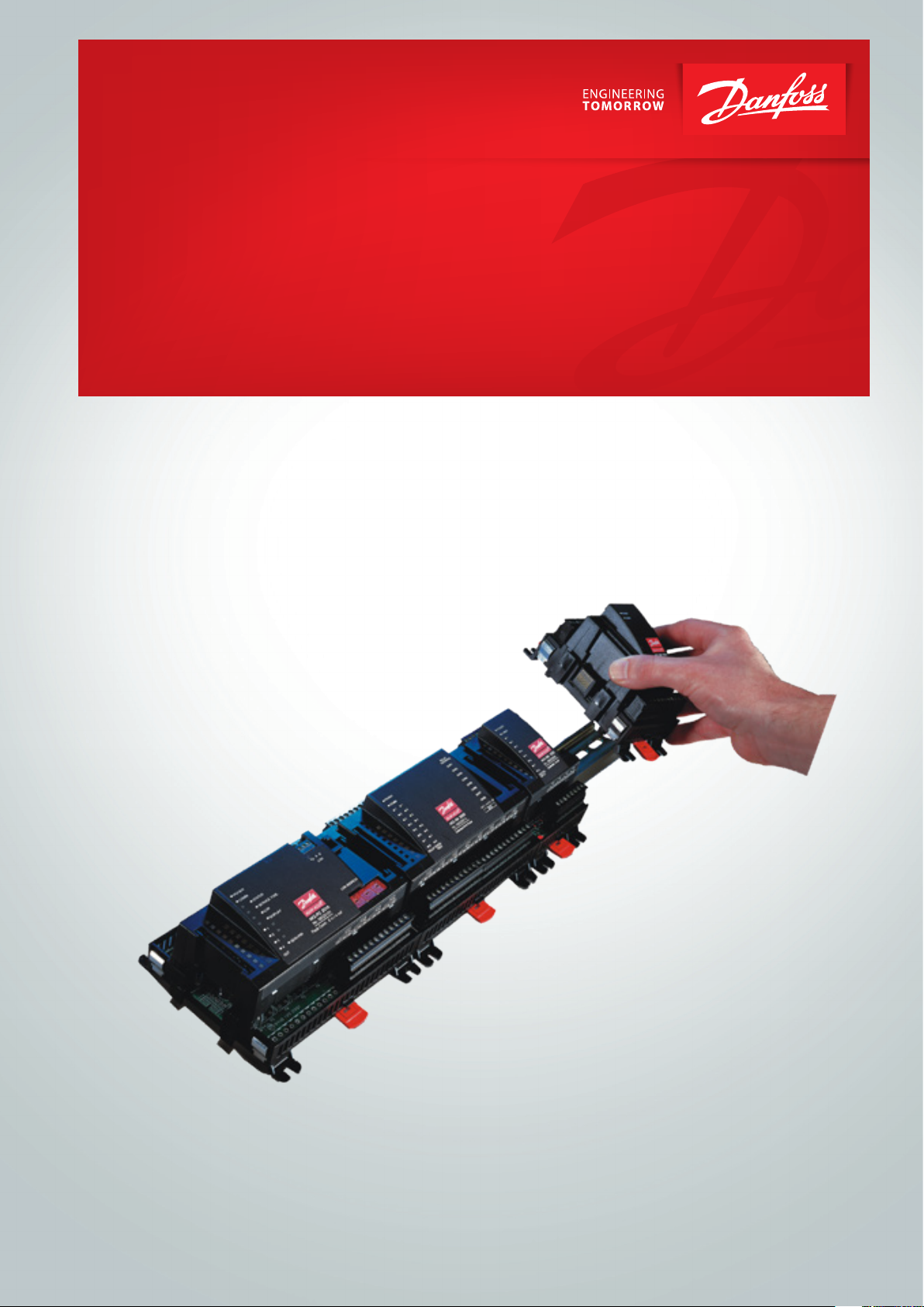
Setup and operation of an AK controller must be accomplished via
the “AK-Service Tool” software program.
The programme is installed on a PC, and setup and operation of
the various functions are carried out via the controller’s menu
displays.
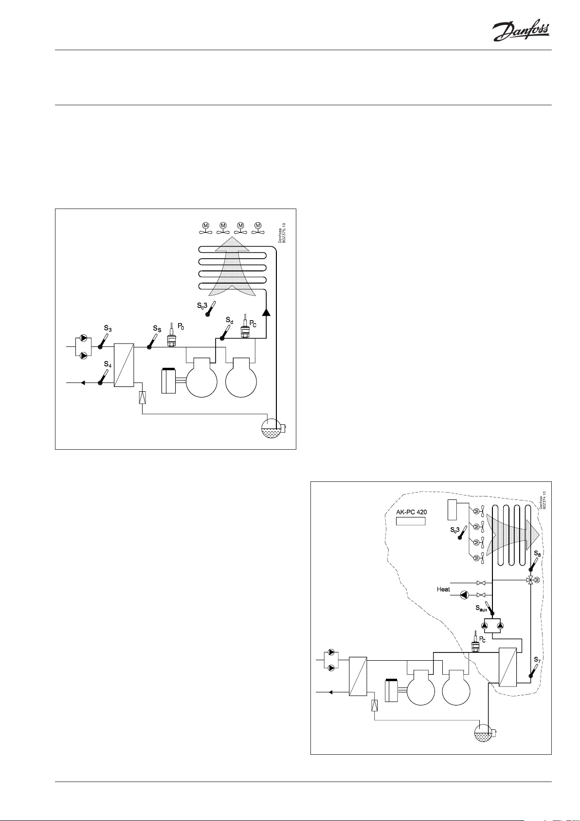
Displays
The menu displays are dynamic, so that dierent settings in one
menu will result in dierent setting possibilities in other menus.
A simple application with few connections will give a setup with
few settings.
A corresponding application with many connections will give a
setup with many settings.
From the overview display there is access to further displays for
the compressor regulation and the condenser regulation.
At the bottom of the display there is access to a number of general
functions, such as “time table”, “manual operation”, “log function”,
“alarms”, and “service” (conguration).
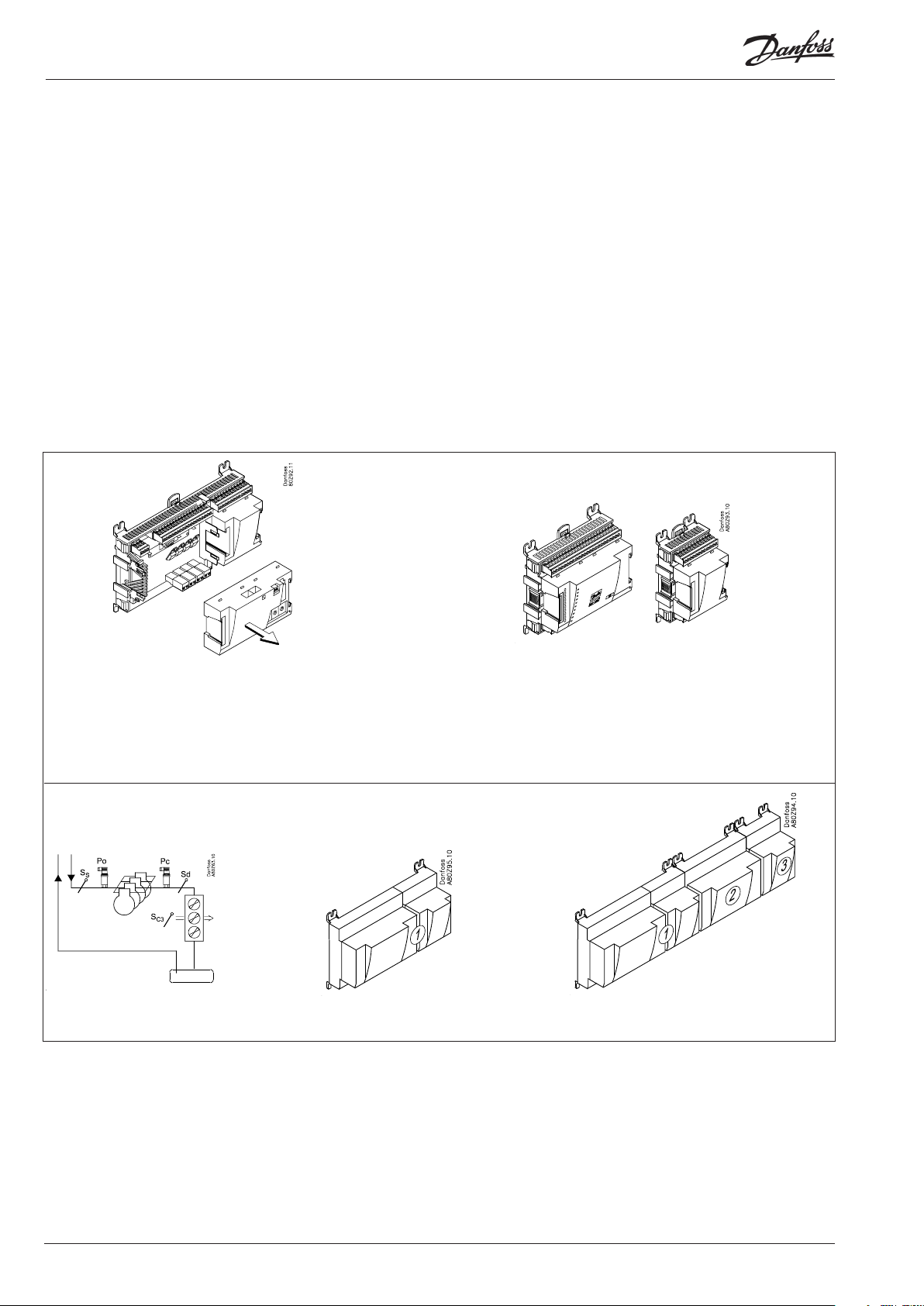
Network linking
The controller can be linked up into a network together with other
controllers in an ADAP-KOOL® refrigeration control system. After
the setup operation can be performed at a distance with, say, our
software program type AKM.
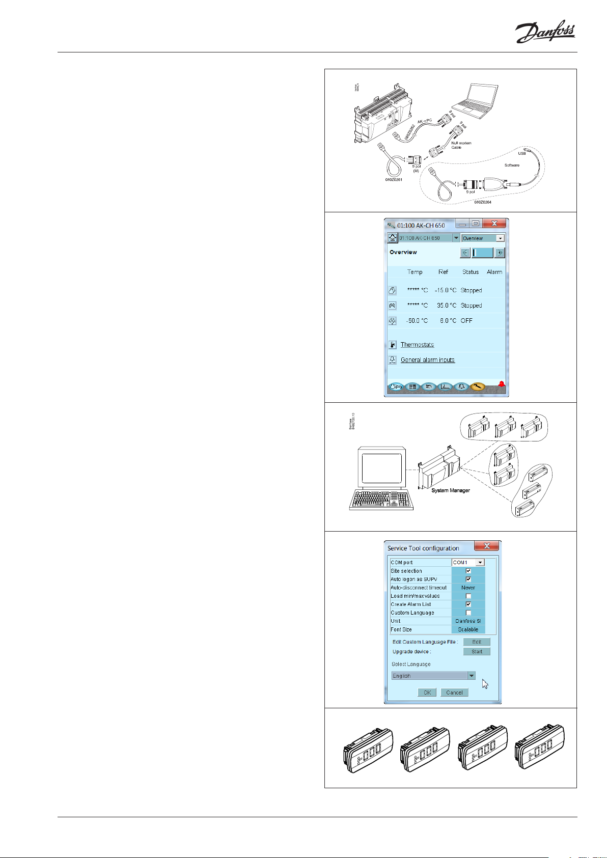
Users
The controller comes supplied with several languages, one of
which can be selected and employed by the user. If there are
several users, they may each have their choice of language. All
users must be assigned a user prole which either gives access to
full operation or gradually limits the operation to the lowest level
that only allows you “to see”.
Language selection is part of the service tool settings.
If the language selection is not available in the service tool for the
current regulator, English texts will be displayed.
External display
An external display can be tted in order for P0 (Suction) and Pc
(Condensing) readings to be displayed.
A total of 4 displays can be tted and with one setting it is possible to choose between the following readings: suction pressure,
suction pressure in temperature, S3, S4, Ss, Sd, condenser pressure, condenser pressure in temperature and S7.
AK-CH 650 Capacity controller RS8ER302 © Danfoss 2016-02 5
Page 6
Light-emitting diodes
A number of light-emitting diodes makes it possible to follow the
signals that are received and transmitted by the controller.
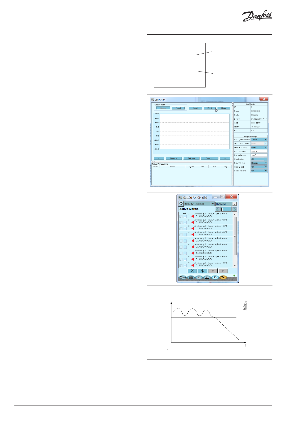
Log
From the log function you can dene the measurements you wish
to be shown.
The collected values can be printed, or you may export them to a
le. You can open the le in Excel.
If you are in a service situation you can show measurements in a
trend function. The measurements are then made realtime and
displayed instantly.
■ Power
■ Comm
■ DO1 ■ Status
■ DO2 ■ Service Tool
■ DO3 ■ LON
■ DO4
■ DO5 ■ Alarm
■ DO6
■ DO7
■ DO8 ■ Service Pin
Slow ash = OK
Quick ash = answer from gateway
Constantly ON = error
Constantly OFF = error
Flash = active alarm/not cancelled
Constant ON = Active alarm/cancelled
Alarm
The display gives you an overview of all active alarms. If you wish
to conrm that you have seen the alarm you can cross it o in the
acknowledge eld.
If you want to know more about a current alarm you can click on it
and obtain an information display on the screen.
A corresponding display exists for all earlier alarms. Here you can
upload information if you need further details about the alarm
history.
Trouble-shooting
The controller contains a function that continuously follows
a number of measurements and deals with them. The result
indicates whether the function is OK or whether an error may
be expected within a given period of time (“the trip down the
rollercoaster has started”). At this time an alarm is transmitted
about the situation – no error has appeared as yet, but it will
come.
One example may be slow clogging-up of a condenser. When the
alarm comes the capacity has been reduced, but the situation is
not serious. There will be time to plan a service call.
Alarm
Error
6 Capacity controller RS8ER302 © Danfoss 2016-02 AK-CH 650
Page 7

2. Design of a controller
This section describes how the controller is designed.
The controller in the system is based on a uniform connection
platform where any deviations from regulation to regulation is
determined by the used top part with a specic software and
by which input and output signals the relevant application will
require. If it is an application with few connections, the controller
module (top part with belonging bottom part) may be sucient.
If it is an application with many connections it will be necessary to
use the controller module plus one or more extension modules.
This section will give you a survey of possible connections plus
assistance in selecting the modules required by your actual
application.
AK-CH 650 Capacity controller RS8ER302 © Danfoss 2016-02 7
Page 8
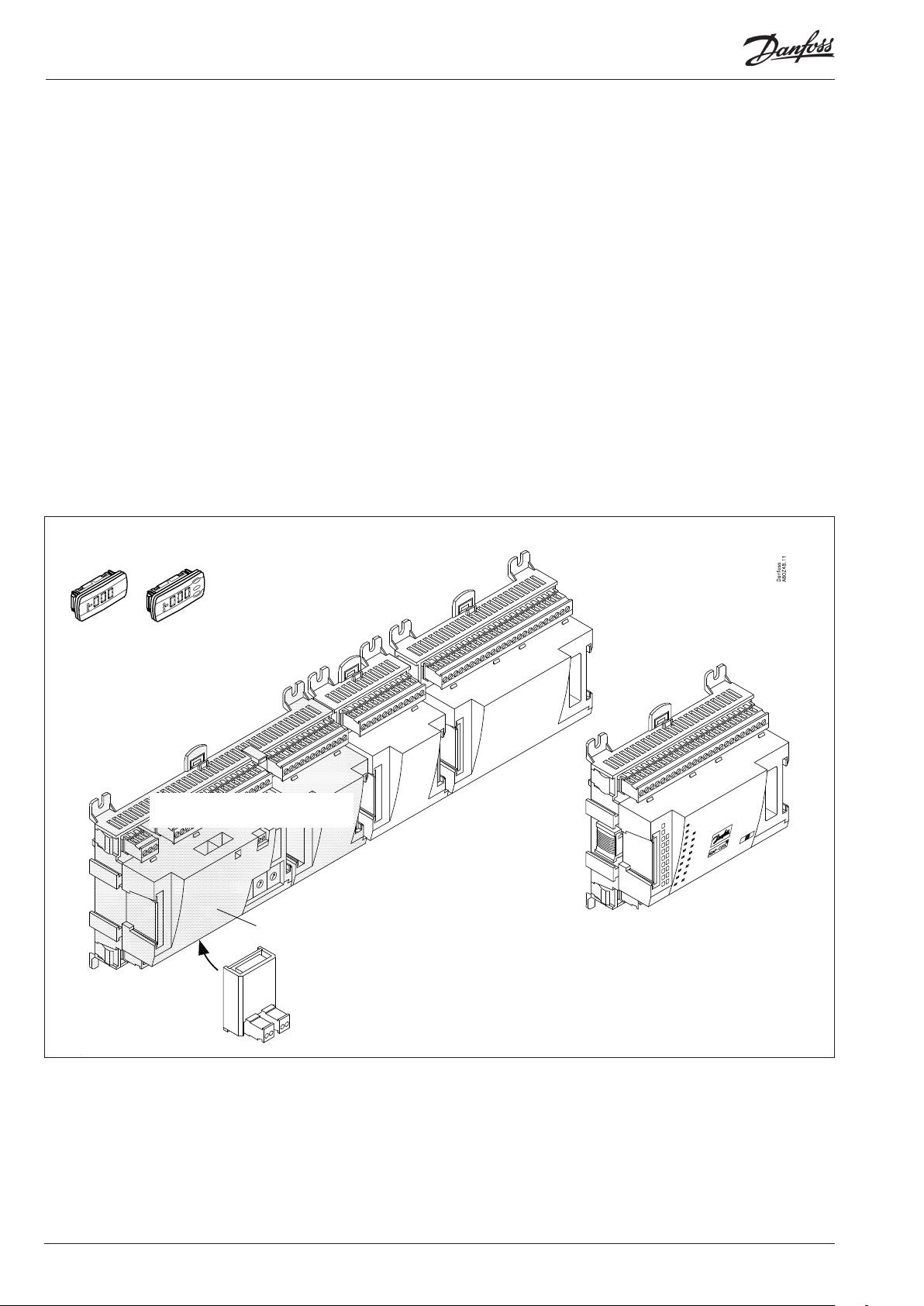
Module survey
• Controller module – capable of handling minor plant requirements.
• Extension modules. When the complexity becomes greater
and additional inputs or outputs are required, modules can be
attached to the controller. A plug on the side of the module will
transmit the supply voltage and data communication between
the modules.
• Top part
The upper part of the controller module contains the
intelligence. This is the unit where the regulation is dened and
where data communication is connected to other controllers in a
bigger network.
• Connection types
There are various types of inputs and outputs. One type may, for
example, receive signals from sensors and switches, another may
receive a voltage signal, and a third type may be outputs with
relays etc. The individual types are shown in the table below.
Extension module with
additional analog inputs
External display for
suction pressure etc.
• Optional connection
When a regulation is planned (set up) it will generate a need for
a number of connections distributed on the mentioned types.
This connection must then be made on either the controller
module or an extension module. The only thing to be observed
is that the types must not be mixed (an analog input signal must
for instance not be connected to a digital input).
• Programming of connections
The controller must know where you connect the individual
input and output signals. This takes place in a later conguration where each individual connection is dened based on the
following principle:
- to which module
- at which point (”terminals”)
- what is connected (e.g. pressure transmitter/type/
pressure range)
Extension module with additional
relay outputs and additional
analog inputs.
Controller with analog inputs and
relay outputs.
Top part
Extension module with
2x analog output signals
The module with additional relay outputs is
also available in a version where the top part
is provided with change-over switches so
that the relays can be overridden.
8 Capacity controller RS8ER302 © Danfoss 2016-02 AK-CH 650
Page 9
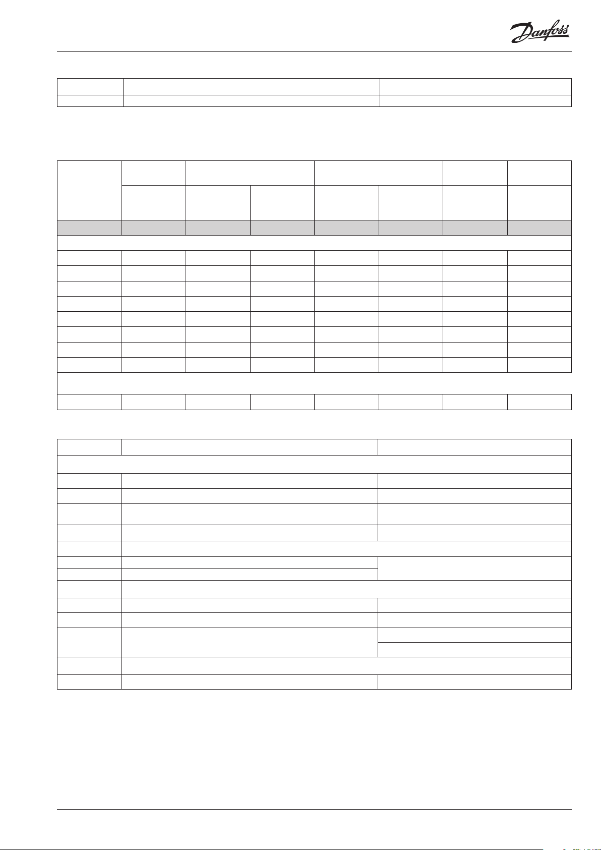
1. Controller
Type Function Application
AK-CH 650 Controller for capacity control of compressors and condensers Extended water chiller control
2. Extension modules and survey of inputs and outputs
Type Analog
inputs
For sensors, pressure transmitters
etc.
Controller 11 4 4 - - - -
Extension modules
AK-XM 101A 8
AK-XM 102A 8
AK-XM 102B 8
AK-XM 103A 4 4
AK-XM 204A 8
AK-XM 204B 8 x
AK-XM 205A 8 8
AK-XM 205B 8 8 x
The following extension module can be placed on the PC board in the controller module.
There is only room for one module.
AK-OB 110 2
On/O outputs On/o supply voltage
Relay
(SPDT)
Solid state Low voltage
(DI signal)
(max. 80 V)
High voltage
(max. 260 V)
Analog
outputs
0-10 V d.c. For override of
Module with
switches
relay outputs
3. AK operation and accessories
Type Function Application
Operation
AK-ST 500 Software for operation of AK controllers AK-operation
- Cable between PC and AK controller AK - Com port
-
- Cable set + converter between PC and AK controller AK - USB
Accessories Power supply module 230 V / 115 V to 24 V
AK-PS 075 18 VA
AK-PS 150 36 VA
Accessories External display that can be connected to the controller module. For showing, say, the suction pressure
EKA 163B Display
EKA 164B Display with operation buttons
- Cable between display and controller
Accessories Real time clock for use in controllers that require a clock function, but are not wired with data communication.
AK-OB 101A Real time clock with battery backup. To be mounted in an AK controller
Cable between zero modem cable and AK controller /
Cable between PDA cable and AK controller
AK - RS 232
Forsyning til regulator
Length = 2 m
Length = 6 m
On the following pages there is data specic to each module.
AK-CH 650 Capacity controller RS8ER302 © Danfoss 2016-02 9
Page 10
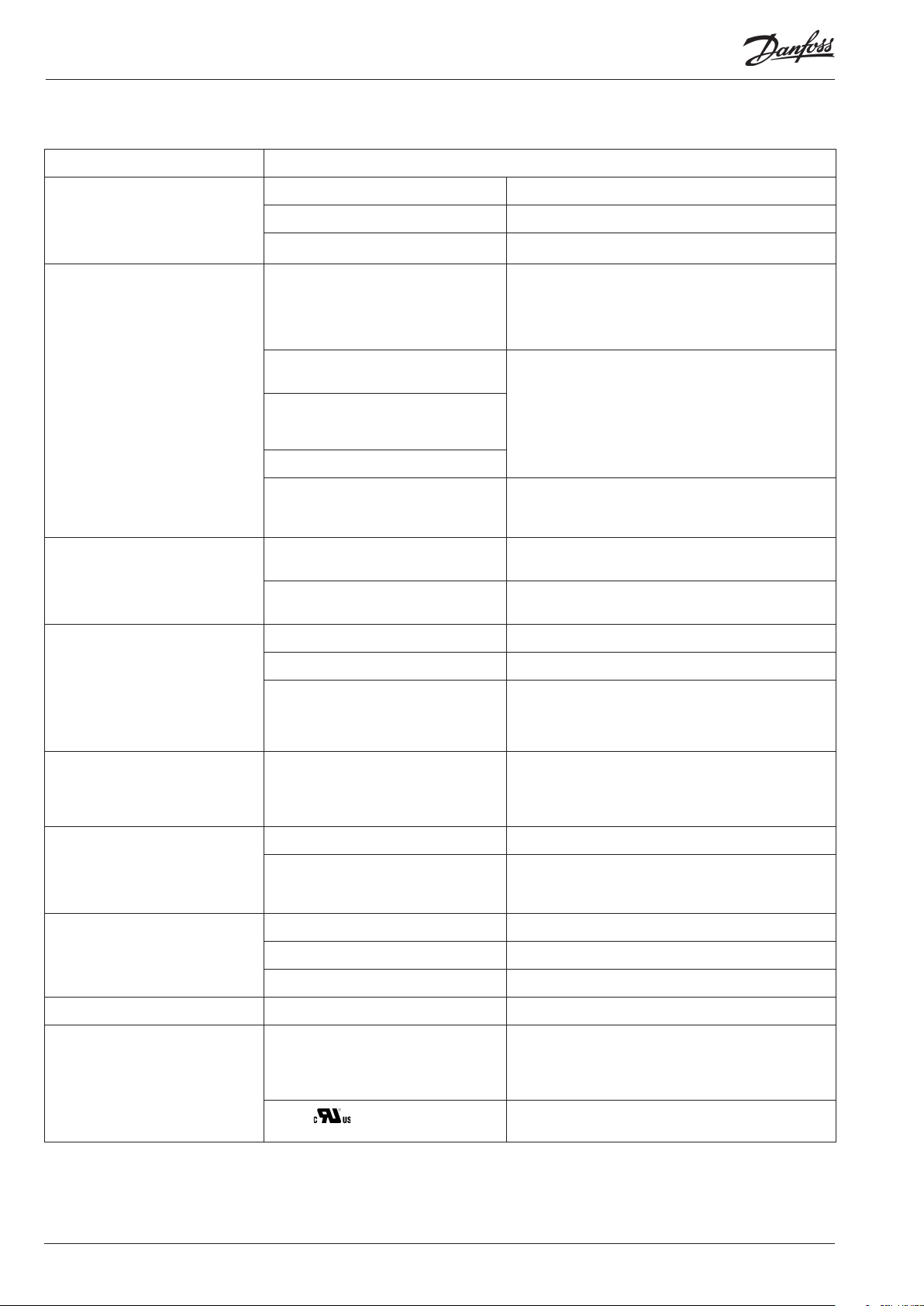
Common data for modules
Supply voltage 24 V d.c./a.c. +/- 20%
Power consumption AK-__ (controller) 8 VA
AK-XM 101, 102 2 VA
AK-XM 204, 205 5 VA
Analoge indgange Pt 1000 ohm /0°C Resolution: 0.1°C
Pressure transmitter type AKS 32R / AKS
2050 / AKS 32 (1-5 V)
Other pressure transmitter:
Ratiometric signal
Min. and Max. pressure must be set
Voltage signal 0-10 V
Contact function (On/O) On at R < 20 ohm
On/o supply voltage inputs Low voltage
Relay outputs
SPDT
0 / 80 V a.c./d.c.
High voltage
0 / 260 V a.c.
AC-1 (ohmic) 4 A
AC-15 (inductive) 3 A
U Min. 24 V
Accuracy:
+/- 0.5°C between -50°C and +50°C
+/- 1°C between -100°C and -50°C
+/- 1°C between +50°C and +130°C
Resolution:1 mV
Accuracy +/- 10 mV
Max. connection of 5 pressure transmitters on one module
O at R > 2K ohm
(Gold -plated contacts not necessary)
O: U < 2 V
On: U > 10 V
O: U < 24 V
On: U > 80 V
Max. 230 V
Low and high voltage must not be connected to the same
output group
Solid state outputs Can be used for loads that are cut in and
out frequently, e.g. :
rail heat, fans and AKV valve
Ambient temperature During transport -40 to 70°C
During operation -20 to 55°C ,
Enclosure Material PC / ABS
Density IP10 , VBG 4
Mounting For mounting on panel wall or DIN rail
Weight with screw terminals modules in100- / 200- / controller-series Ca. 200 g / 500 g / 600 g
Approvals EU low voltage directive and EMC require-
ments are complied with
UL 873,
The mentioned data applies to all modules.
If data is specic, this is mentioned together with the module in question.
Capacitive load
The relays cannot be used for the direct connection of capacitive loads such as LEDs
and on/o control of EC motors.
All loads with a switch mode power supply must be connected with a suitable contactor or similar.
Max. 240 V a.c. , Min. 48 V a.c.
Max. 0.5 A,
Leak < 1 mA
Max. 1 AKV
0 to 95% RH (non condensing)
No shock inuences / vibrations
LVD tested according to EN 60730
EMC tested
Immunity according to EN 61000-6-2
Emission according to EN 61000-6-3
UL le number: E31024 for CH
UL le number: E166834 for XM
10 Capacity controller RS8ER302 © Danfoss 2016-02 AK-CH 650
Page 11
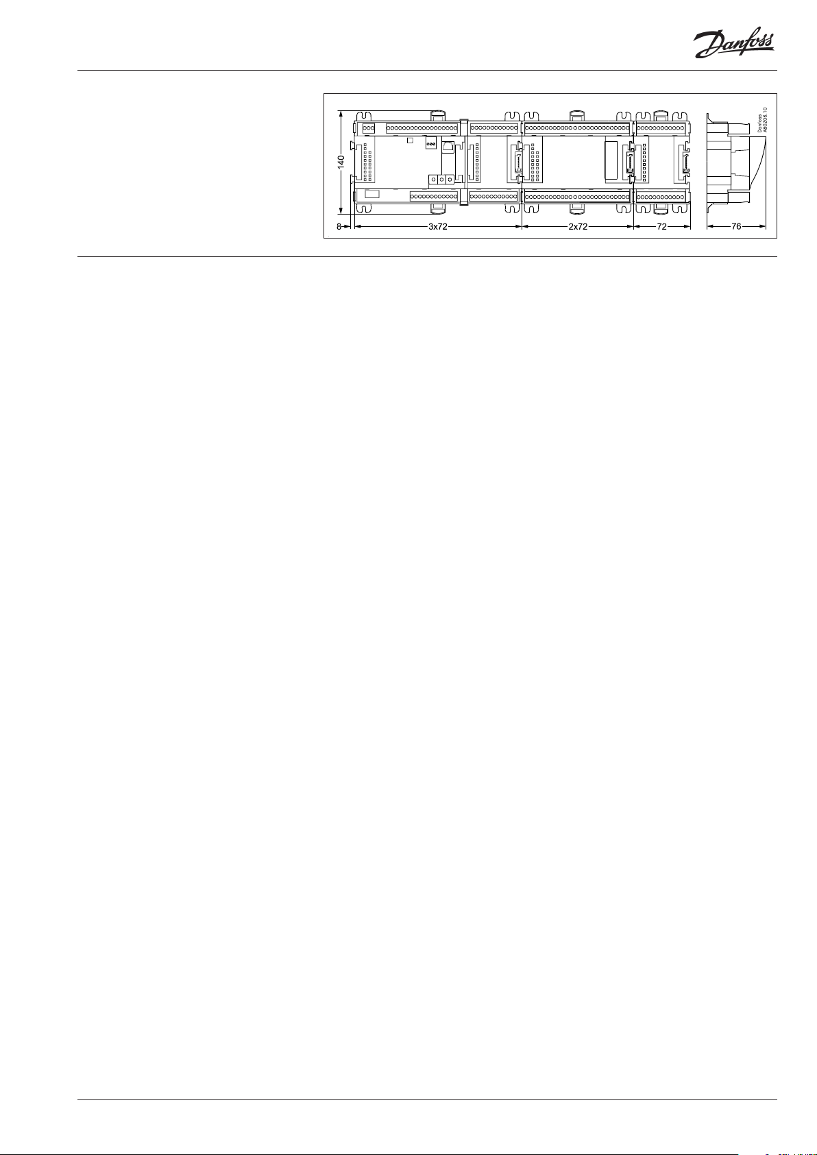
Dimensions
The module dimension is 72 mm.
Modules in the 100-series consist of one
module
Modules in the 200-series consist of two
modules
Controllers consist of three modules
The length of an aggregate unit = n x 72 + 8
AK-CH 650 Capacity controller RS8ER302 © Danfoss 2016-02 11
Page 12
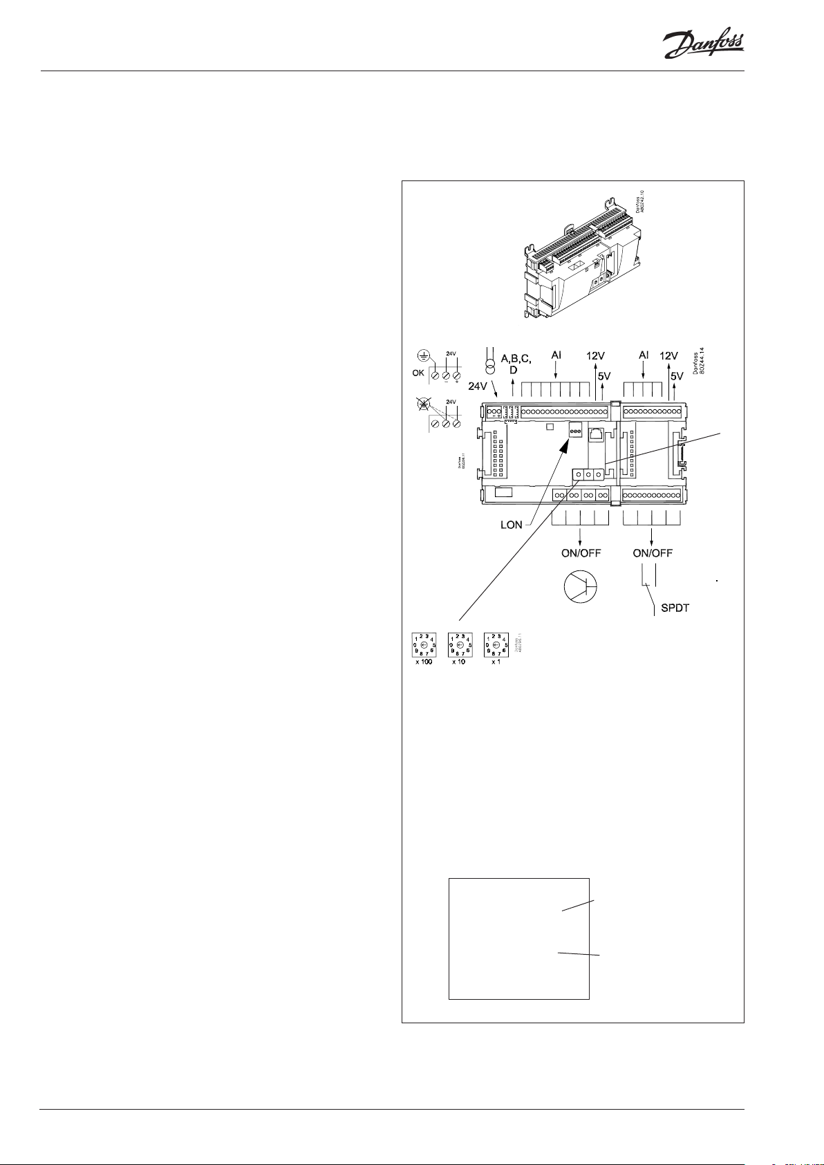
Controller
Function
There are several controllers in the series. The function is
determined by the programmed software, but outwardly the
controllers are identical – they all have the same connection
possibilities:
11 analog inputs for sensors, pressure transmitters, voltage signals
and contact signals.
8 digital outputs, with 4 Solid state outputs and 4 relay outputs
Supply voltage
24 V a.c. or d.c. to be connected to the controller.
The 24 V must not be retransmitted and used by other controllers
as it is not galvanically separated from inputs and outputs. In
other words, you must use a transformer for each controller. Class
II is required. The terminals must not be earthed.
The supply voltage to any extension modules is transmitted via
the plug on the right-hand side.
The size of the transformer is determined by the power
requirement of the total number of modules.
The supply voltage to a pressure transmitter can be taken either
from the 5 V output or from the 12 V output depending on
transmitter type.
PIN
Data communication
If the controller is to be included in a system, communication
must take place via the LON connection.
The installation has to be made as mentioned in the separate
instructions for LON communication.
Address setting
When the controller is connected to a gateway type AKA 245, the
controller’s address must be set between 1 and 119.
Service PIN
When the controller is connected to the data communication
cable the gateway must have knowledge of the new controller.
This is obtained by pushing the key PIN. The LED “Status” will ash
when the gateway sends an acceptance message.
Operation
The conguration operation of the controller must take place from
the software programme “Service Tool”. The program must be
installed on a PC, and the PC must be connected to the controller
via the network plug on the front of the unit.
Light-emitting diodes
There are two rows with LED’s. They mean:
Left row:
• Voltage supply to the controller
• Communication active with the bottom PC board (red = error)
• Status of outputs DO1 to DO8
Right row:
• Software status (slow ash = OK)
• Communication with Service Tool
• Communication on LON
• Alarm when LED ashes
- 3 LED’s that are not used
• “Service Pin” switch has been activated
Address
■ Power
■ Comm
■ DO1 ■ Status
■ DO2 ■ Service Tool
■ DO3 ■ LON
■ DO4
■ DO5 ■ Alarm
■ DO6
■ DO7
■ DO8 ■ Service Pin
Slow ash = OK
Quick ash = answer from gateway
Constantly ON = error
Constantly OFF = error
Flash = active alarm/not cancelled
Constant ON = Active alarm/cancelled
Keep the safety
distance!
Low and high
voltage must not
be connected to
the same output
group
A small module (option board) can be placed on the bottom part
of the controller. The module is described later in the document.
12 Capacity controller RS8ER302 © Danfoss 2016-02 AK-CH 650
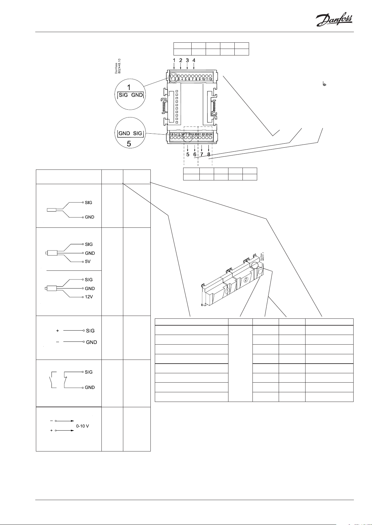
Page 13
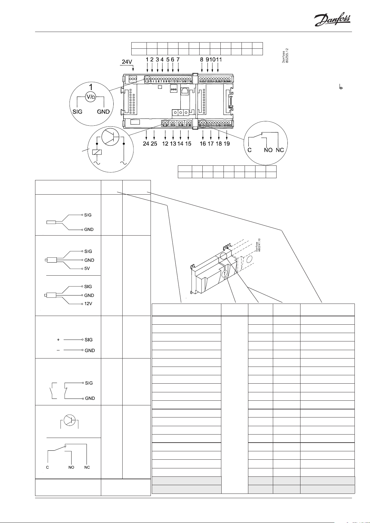
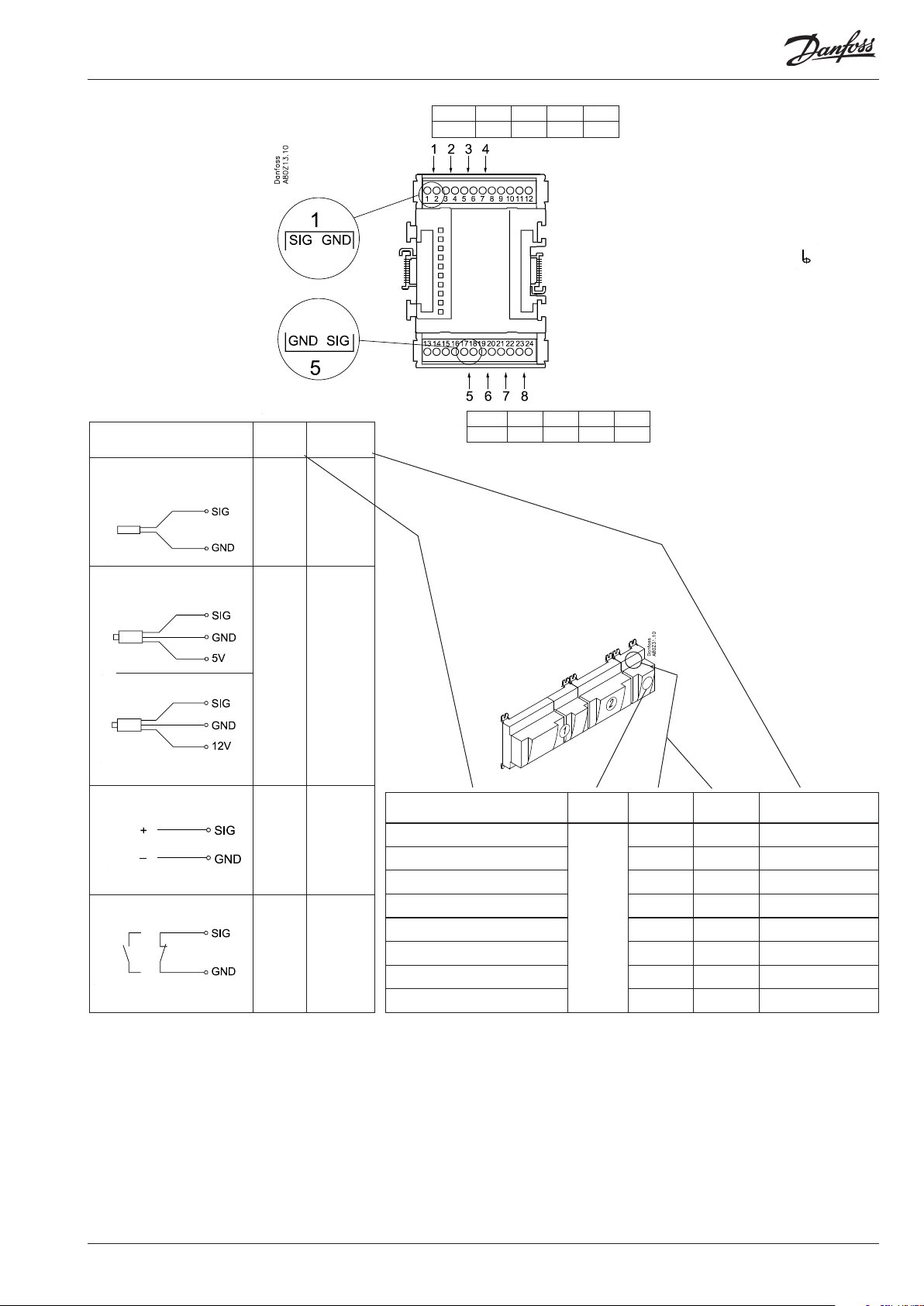
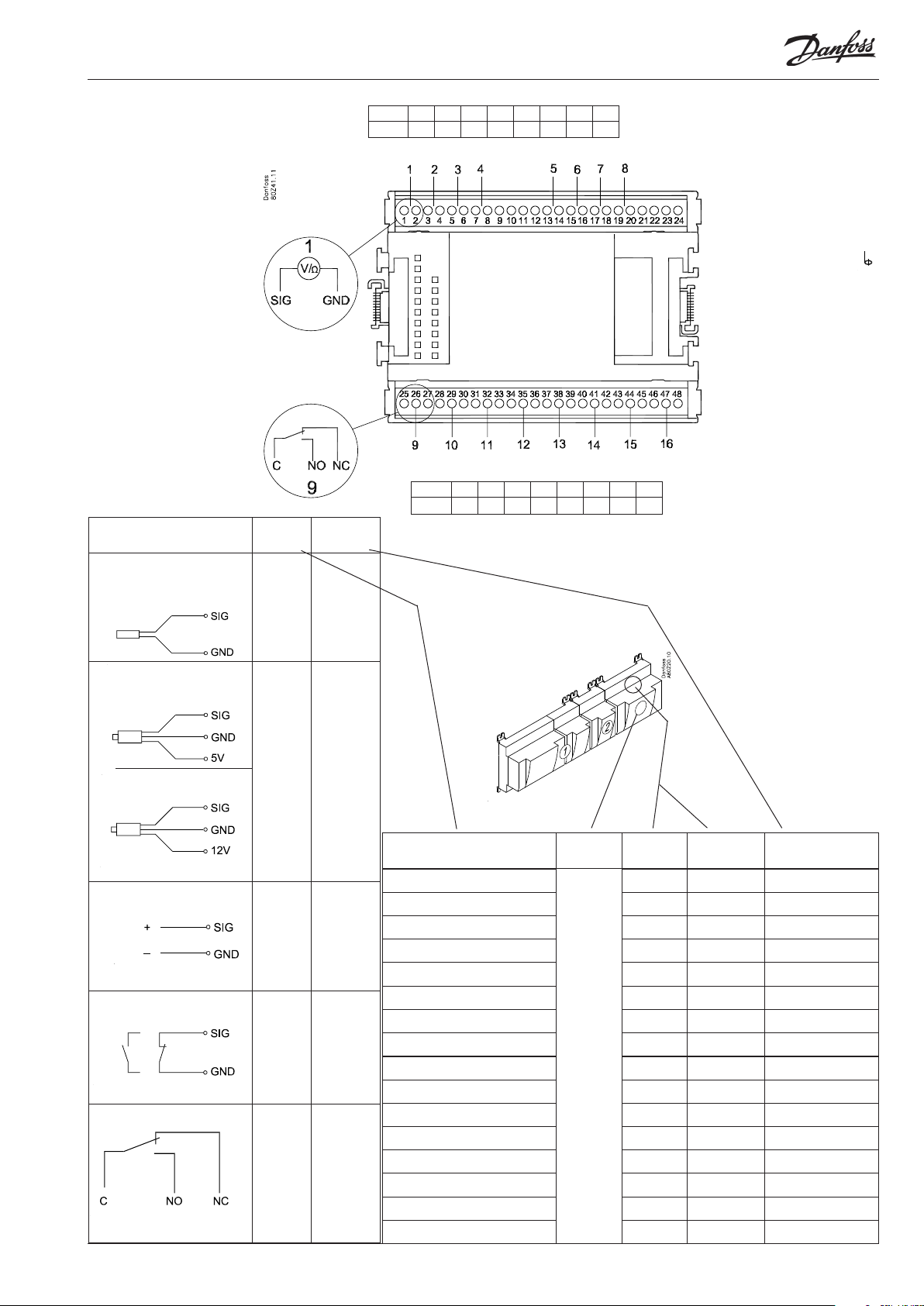
Point
Point 1 2 3 4 5 6 7 8 9 10 11
Type AI1 AI2 AI3 AI4 AI5 AI6 AI7 AI8 AI9 AI10 AI11
Terminal 15: 12 V
Terminal 16: 5 V
Terminal 27: 12 V
Terminal 28: 5 V
Analog
inputs
on 1 - 11
Solid state outputs
on 12 - 15
Relay or AKV coil
fx 230 V a.c.
Signal Signal
S
Pt 1000 ohm/0°C
S1
S2
Saux1
Saux2
SSA
SdA
P
AKS 32R
3: Brown
2: Blue
1: Black
P0A
P0B
PcA
AKS 32
3: Brown
2: Black
1: Red
PcB
U
...
On/O Ext.
Main
switch
Day/
Night
Door
DO
AKV
AKV
Comp 1
Comp 2
Fan 1
Alarm
Light
Rail heat
Defrost
Option Board
Please see the signal
on the page with the
module.
24 and 25 used
only when "Option board tted"
type
Pt 1000
AKS 32R /
AKS 2050 /
MBS 8250
-1 - xx bar
AKS 32
-1 - zz bar
0 - 5 V
0 - 10 V
Active at:
Closed
/
Open
Active at:
On
/
O
Point 12 13 14 15 16 17 18 19
Type DO1 DO2 DO3 DO4 DO5 DO6 DO7 DO8
Signal Module Point
1 (AI 1) 1 - 2
2 (AI 2) 3 - 4
3 (AI 3) 5 - 6
4 (AI 4) 7 - 8
5 (AI 5) 9 - 10
6 (AI 6) 11 - 12
7 (AI 7) 13 - 14
8 (AI 8) 19 - 20
9 (AI 9) 21 - 22
10 (AI 10) 23 - 24
11 (AI 11) 25 - 26
1
12 (DO 1) 31 - 32
13 (DO 2) 33 - 34
14 (DO 3) 35 - 36
15 (DO 4) 37 - 38
16 (DO 5) 39 - 40 - 41
17 (DO6) 42 -43 - 44
18 (DO7) 45 - 46- 47
19 (DO8) 48 - 49 -50
24 -
25 -
Terminal
17, 18, 29, 30:
(Cable screen)
Relay outputs on
16 - 19
Terminal
Signal type /
Active at
AK-CH 650 Capacity controller RS8ER302 © Danfoss 2016-02 13
Page 14
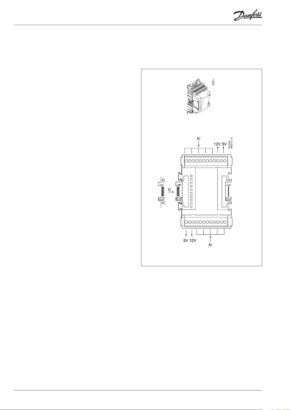
Extension module AK-XM 101A
Function
The module contains 8 analog inputs for sensors, pressure
transmitters, voltage signals and contact signals.
Supply voltage
The supply voltage to the module comes from the previous
module in the row.
Supply voltage to a pressure transmitter can be taken from either
the 5 V output or the 12 V output depending on transmitter type.
Light-emitting diodes
Only the two top LED’s are used. They indicate the following:
• Voltage supply to the module
• Communication with the controller is active (red = error)
14 Capacity controller RS8ER302 © Danfoss 2016-02 AK-CH 650
Page 15
Point
Point 1 2 3 4
Type AI1 AI2 AI3 AI4
Terminal 9: 12 V
Terminal 10: 5 V
S
Pt 1000 ohm/0°C
P
AKS 32R
AKS 32
At the top the
signal input is
the left of the
two terminals.
At the bottom
the signal input
is the right of the
two terminals.
3: Brown
2: Blue
1: Black
3: Brown
2: Black
1: Red
Signal Signal
type
S1
S2
Saux1
Pt 1000
Saux2
SSA
SdA
AKS 32R /
P0A
P0B
PcA
PcB
AKS 2050 /
MBS 8250
-1 - xx bar
AKS 32
-1 - zz bar
Terminal 15: 5 V
Terminal 16: 12 V
Terminal
11, 12, 13, 14:
(Cable screen)
Point 5 6 7 8
Type AI5 AI6 AI7 AI8
U
...
On/O Ext.
Main
switch
Day/
Night
Door
0 - 5 V
0 - 10 V
Active at:
Closed
/
Open
Signal Module Point
1 (AI 1) 1 - 2
2 (AI 2) 3 - 4
3 (AI 3) 5 - 6
4 (AI 4) 7 - 8
5 (AI 5) 17 - 18
6 (AI 6) 19 - 20
7 (AI 7) 21 - 22
8 (AI 8) 23 - 24
Terminal
Signal type /
Active at
AK-CH 650 Capacity controller RS8ER302 © Danfoss 2016-02 15
Page 16
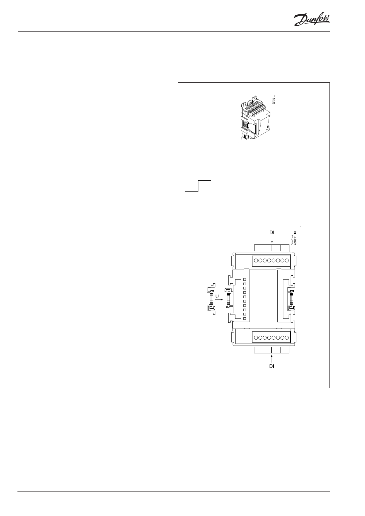
Extension module AK-XM 102A / AK-XM 102B
Function
The module contains 8 inputs for on/o voltage signals.
Signal
AK-XM 102A is for low voltage signals.
AK-XM 102B is for high voltage signals.
Supply voltage
The supply voltage to the module comes from the previous
module in the row.
Light-emitting diodes
They indicate:
• Voltage supply to the module
• Communication with the controller is active (red = error)
• Status of the individual inputs 1 to 8 (when lit = voltage)
AK-XM 102A
Max. 24 V
On/O:
On: DI > 10 V a.c.
O: DI < 2 V a.c.
AK-XM 102B
Max. 230 V
On/O:
On: DI > 80 V a.c.
O: DI < 24 V a.c.
16 Capacity controller RS8ER302 © Danfoss 2016-02 AK-CH 650
Page 17
Point
DI
AK-XM 102A: Max. 24 V
AK-XM 102B: Max. 230 V
Signal Active at
Ext.
Main
switch
Day/
Night
Comp.
safety 1
Comp.
safety 2
Closed
(voltage on)
/
Open
(voltage o)
Point 1 2 3 4
Type DI1 DI2 DI3 DI4
Point 5 6 7 8
Type DI5 DI6 DI7 DI8
Signal Module Point Terminal Active at
1 (DI 1) 1 - 2
2 (DI 2) 3 - 4
3 (DI 3) 5 - 6
4 (DI 4) 7 - 8
5 (DI 5) 9 - 10
6 (DI 6) 11 - 12
7 (DI 7) 13 - 14
8 (DI 8) 15 - 16
AK-CH 650 Capacity controller RS8ER302 © Danfoss 2016-02 17
Page 18
Extension module AK-XM 103A
Function
The module contains :
4 analog inputs for sensors, pressure transmitters, voltage signals
and contact signals.
4 analog voltage outputs of 0 - 10 V
Supply voltage
The supply voltage to the module comes from the previous
module in the row.
Supply voltage to a pressure transmitter can be taken from either
the 5 V output or the 12 V output depending on transmitter type.
Galvanic isolation
The inputs are galvanically separated from the outlets.
The outlets AO1 and AO2 are galvanically separated from AO3 and
AO4.
Light-emitting diodes
Only the two top LED’s are used. They indicate the following:
• Voltage supply to the module
• Communication with the controller is active (red = error)
Max. load
I < 2.5 mA
R > 4 kΩ
18 Capacity controller RS8ER302 © Danfoss 2016-02 AK-CH 650
Page 19
Point
Point 1 2 3 4
Type AI1 AI2 AI3 AI4
Terminal 9: 12 V
Terminal 10: 5 V
S
Pt 1000 ohm/0°C
P
AKS 32R
AKS 32
At the top the
signal input is
the left of the
two terminals.
At the bottom
the signal input
is the right of the
two terminals.
3: Brown
2: Blue
1: Black
3: Brown
2: Black
1: Red
Signal Signal
type
S1
S2
Saux
SsA
Pt 1000
SdA
Shr
Stw
Sgc
P0A
P0B
PcA
PcB
Paux
Pgc
Prec
AKS 32R /
AKS 2050
MBS 8250
-1 - xx bar
AKS 32
-1 - zz bar
Terminal
11, 12:
(Cable screen)
Galvanic isolation:
AI 1-4 ≠ AO 1-2 ≠ AO 3-4
Point 5 6 7 8
Type AO1 AO2 AO3 AO 4
U
...
On/O Ext.
Main
switch
Day/
Night
Door
Level
switch
AO
0 - 5 V
0 - 10 V
Active at:
Closed
/
Open
0-10 V
Signal Module Point Terminal Signal type /Active at
1 (AI 1) 1 - 2
2 (AI 2) 3 - 4
3 (AI 3) 5 - 6
4 (AI 4) 7 - 8
5 (AO 1) 17 - 18
6 (AO 2) 19 - 20
7 (AO 3) 21 - 22
8 (AO 4) 23 - 24
AK-CH 650 Capacity controller RS8ER302 © Danfoss 2016-02 19
Page 20
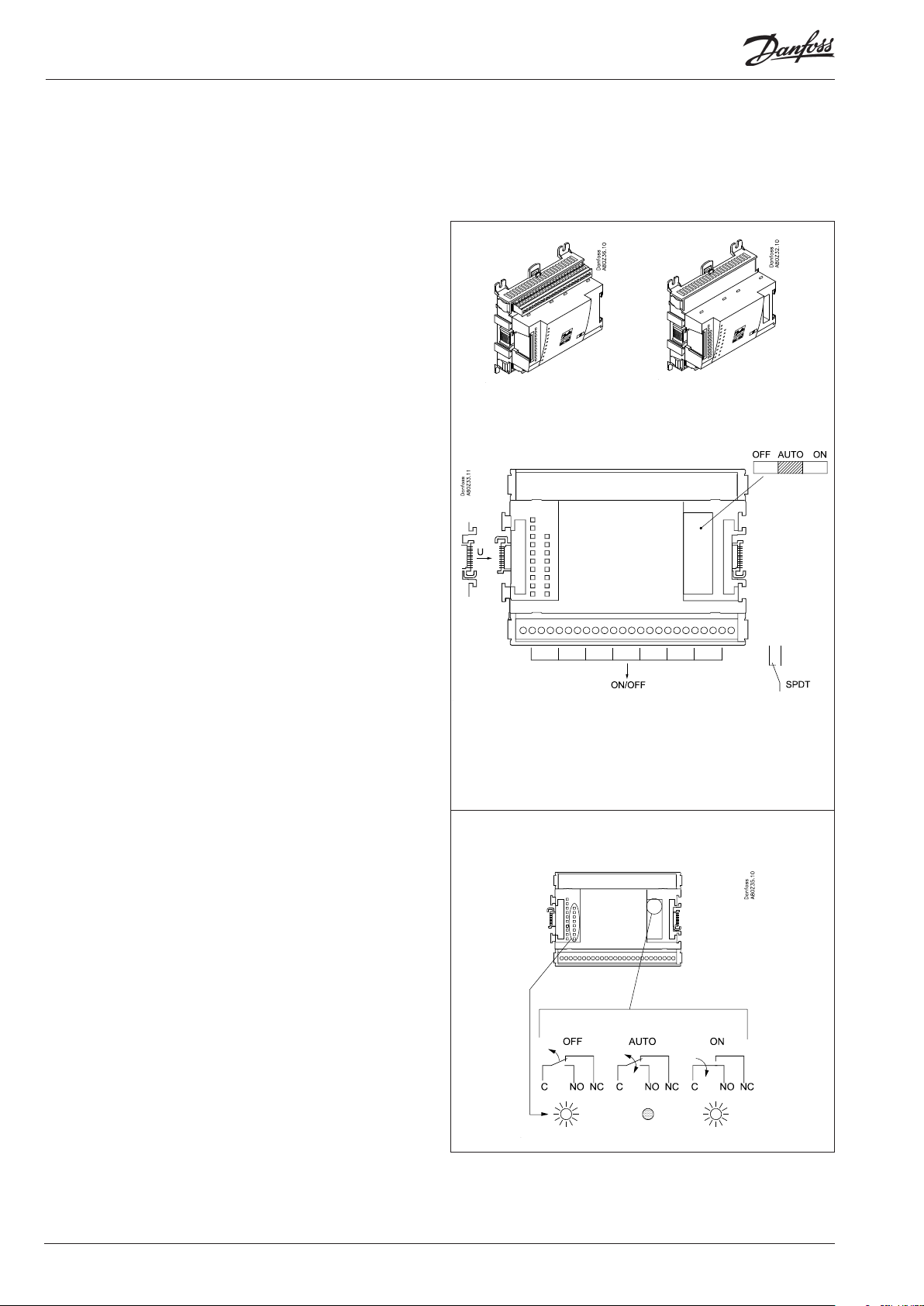
Extension module AK-XM 204A / AK-XM 204B
Function
The module contains 8 relay outputs.
Supply voltage
The supply voltage to the module comes from the previous
module in the row.
AK-XM 204B only
Override of relay
Eight change-over switches at the front make it possible to
override the relay’s function.
Either to position OFF or ON.
In position Auto the controller carries out the control.
Light-emitting diodes
There are two rows with LED’s. They indicate the following:
Left row:
• Voltage supply to the controller
• Communication active with the bottom PC board (red = error)
• Status of outputs DO1 to DO8
Right row: (AK-XM 204B only):
• Override of relays
ON = override
OFF = no override
AK-XM 204A AK-XM 204B
Fuses
Behind the upper part there is a fuse for each output.
Max. 230 V
AC-1: max. 4 A (ohmic)
AC-15: max. 3 A (Inductive)
AK-XM 204B
Override of relay
Keep the safety distance!
Low and high voltage
must not be connected to
the same output group
20 Capacity controller RS8ER302 © Danfoss 2016-02 AK-CH 650
Page 21
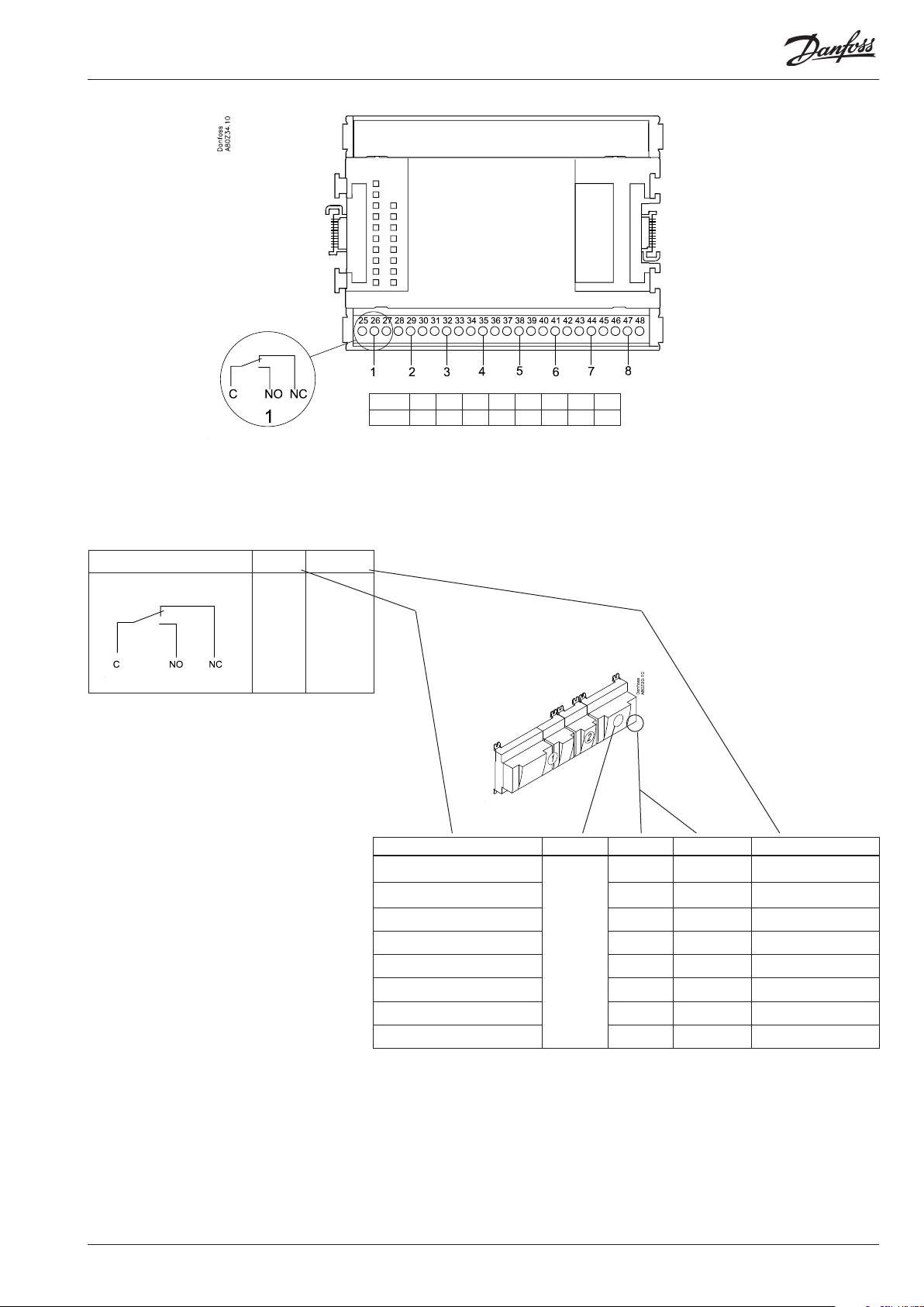
Point
DO
Signal Active at
Comp. 1
Comp. 2
Fan 1
Alarm
On
/
O
Point 1 2 3 4 5 6 7 8
Type DO1 DO2 DO3 DO4 DO5 DO6 DO7 DO8
Signal Module Point Terminal Active at
1 (DO 1) 25 -26 - 27
2 (DO 2) 28 - 27 - 30
3 (DO 3) 31 - 32 - 33
4 (DO 4) 34 - 35 -36
5 (DO 5) 37 - 38 - 39
6 (DO 6) 40 - 41 - 42
7 (DO 7) 43 - 44 - 45
8 (DO 8) 46 - 47 - 48
AK-CH 650 Capacity controller RS8ER302 © Danfoss 2016-02 21
Page 22
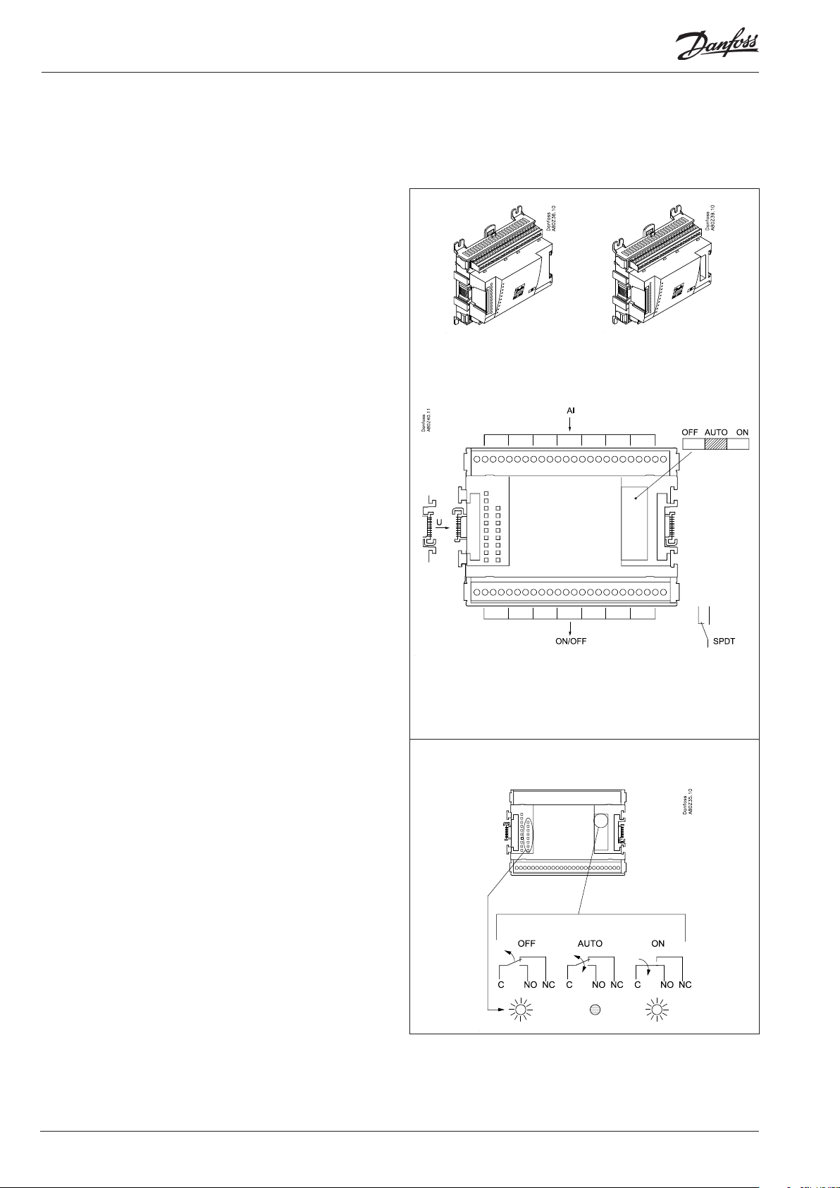
Extension module AK-XM 205A / AK-XM 205B
Function
The module contains:
8 analog inputs for sensors, pressure transmitters, voltage signals
and contact signals.
8 relay outputs.
Supply voltage
The supply voltage to the module comes from the previous
module in the row.
AK-XM 205B only
Override of relay
Eight change-over switches at the front make it possible to
override the relay’s function.
Either to position OFF or ON.
In position Auto the controller carries out the control.
Light-emitting diodes
There are two rows with LED’s. They mean:
Left row:
• Voltage supply to the controller
• Communication active with the bottom PC board (red = error)
• Status of outputs DO1 to DO8
Right row: (AK-XM 205B only):
• Override of relays
ON = override
OFF = no override
AK-XM 205A AK-XM 205B
max. 10 V
Fuses
Behind the upper part there is a fuse for each output.
Max. 230 V
AC-1: max. 4 A (ohmic)
AC-15: max. 3 A (Inductive)
AK-XM 205B
Override of relay
Keep the safety distance!
Low and high voltage
must not be connected to
the same output group
22 Capacity controller RS8ER302 © Danfoss 2016-02 AK-CH 650
Page 23
Point
S
Pt 1000 ohm/0°C
Signal Signal
type
S1
S2
Saux1
Pt 1000
Saux2
SSA
SdA
Point 1 2 3 4 5 6 7 8
Type AI1 AI2 AI3 AI4 AI5 AI6 AI7 AI8
Terminal 9: 12 V
Terminal 10: 5 V
Terminal 21: 12 V
Terminal 22: 5 V
Terminal 11, 12, 23, 24 :
(Cable screen)
Point 9 10 11 12 13 14 15 16
Type DO1 DO2 DO3 DO4 DO5 DO6 DO7 DO8
P
AKS 32R
AKS 32
U
On/O
DO
3: Brown
2: Blue
1: Black
3: Brown
2: Black
1: Red
P0A
P0B
PcA
PcB
...
Ext.
Main
switch
Day/
Night
Door
Comp 1
Comp 2
Fan 1
Alarm
Light
Rail
heat
Defrost
AKS 32R /
AKS 2050 /
MBS 8250
-1 - xx bar
AKS 32
-1 - zz bar
0 - 5 V
0 - 10 V
Active at:
Closed
/
Open
Active at:
on
/
O
Signal Module Point
1 (AI 1) 1 - 2
2 (AI 2) 3 - 4
3 (AI 3) 5 - 6
4 (AI 4) 7 - 8
5 (AI 5) 13 - 14
6 (AI 6) 15 - 16
7 (AI 7) 17 - 18
8 (AI 8) 19 -20
9 (DO 1) 25 - 26 - 27
10 (DO 2) 28 - 29 - 30
11 (DO 3) 31 - 32 - 33
12 (DO 4) 34 - 35 - 36
13 (DO 5) 37 - 38 - 39
14 (DO6) 40 - 41 - 42
15 (DO7) 43 - 44 - 45
16 (DO8) 46 - 47 - 48
Terminal
Signal type /
Active at
AK-CH 650 Capacity controller RS8ER302 © Danfoss 2016-02 23
Page 24
Extension module AK-OB 110
Function
The module contains two analog voltage outputs of 0 – 10 V.
Supply voltage
The supply voltage to the module comes from the controller
module.
Placing
The module is placed on the PC board in the controller module.
Point
The two outputs have points 24 and 25. They are shown on the
earlier page where the controller is also mentioned.
Max. load
I < 2,5 mA
R > 4 kohm
AO
AO 0 - 10 V
Module
Point 24 25
Type AO1 AO2
1
AO2
AO1
24 Capacity controller RS8ER302 © Danfoss 2016-02 AK-CH 650
Page 25
Extension module AK-OB 101A
Function
The module is a real time clock module with battery backup.
The module can be used in controllers that are not linked up in
a data communication unit together with other controllers. The
module is used here if the controller needs battery backup for the
following functions
• Clock function
• Fixed times for day/night change-over
• Fixed defrost times
• Saving of alarm log in case of power failure
• Saving of temperature log in case of power failure
Connection
The module is provided with plug connection.
Placing
The module is placed on the PC board inside the top part.
Point
No point for a clock module to be dened – just connect it.
Working life of the battery
The working life of the battery is several years – even if there are
frequent power failures.
An alarm is generated when the battery has to be replaced.
After the alarm there are still several months of operating hours
left in the battery.
AK-CH 650 Capacity controller RS8ER302 © Danfoss 2016-02 25
Page 26
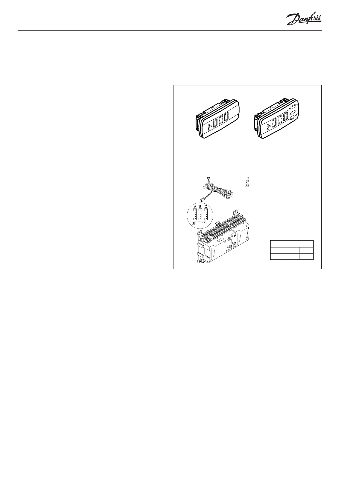
Extension module EKA 163B / EKA 164B
Function
Display of important measurements from the controller, e.g. appli-
ance temperature, suction pressure or condensing pressure.
Setting of the individual functions can be performed by using the
display with control buttons.
It is the controller used that determines the measurements and
settings that can occur.
Connection
The extension module is connected to the controller module via
a cable with plug connections. You have to use one cable per
module. The cable is supplied in various lengths.
Both types of display (with or without control buttons) can be
connected to either display output A, B, C or D.
When the controller starts up, the display will show the output
that is connected.
- - 1 = output A
- - 2 = output B
etc.
EKA 163B EKA 164B
Placing
The extension module can be placed at a distance of up to 15 m
from the controller module.
Point
No point has to be dened for a display module – you simply connect it.
Module
Point - Type - -
1
26 Capacity controller RS8ER302 © Danfoss 2016-02 AK-CH 650
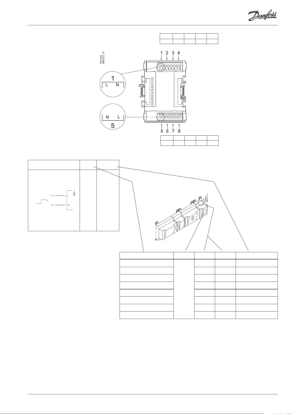
Page 27
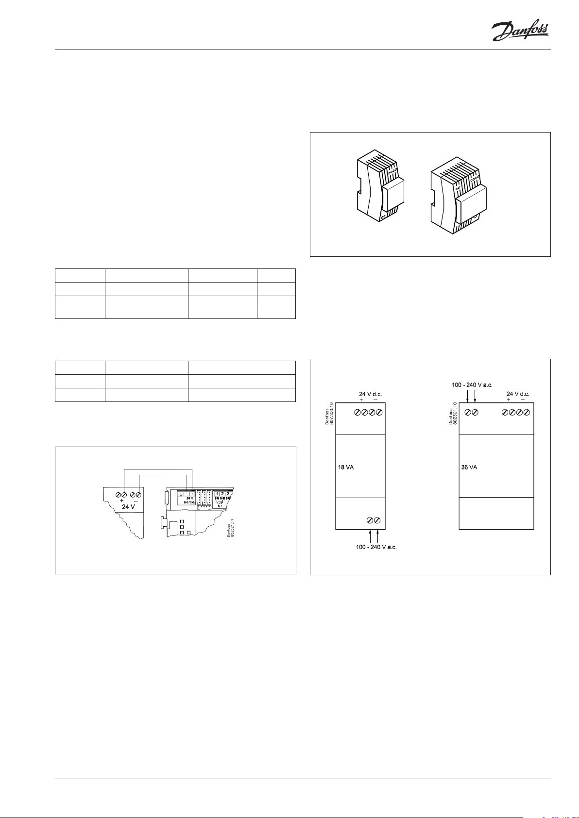
Power supply module AK-PS 075 / 150
Function
24 V supply for controller.
Supply voltage
230 V a.c or 115 V a.c. (from 100 V a.c. to 240 V a.c.)
Placing
On DIN-rail
Eect
Type Output tension Output current Power
AK-PS 075 24 V d.c. 0.75 A 18 VA
AK-PS 150 24 V d.c.
(adjustable)
1.5 A 36 VA
Dimension
Type High Width
AK-PS 075 90 mm 36 mm
AK-PS 150 90 mm 54 mm
Supply to a controller
Connections
AK-PS 075
AK-PS 150
AK-CH 650 Capacity controller RS8ER302 © Danfoss 2016-02 27
Page 28

Preface to design
Be aware of the following when the number of extension modules
is being planned. A signal may have to be changed, so that an
additional module may be avoided.
• An ON/OFF signal can be received in two ways. Either as a
contact signal on an analog input or as voltage on a low or highvoltage module.
• An ON/OFF output signal can be given in two ways. Either with a
relay switch or with solid state. The primary dierence is the permitted load and that the relay switch contains a cutout switch.
Mentioned below is a number of functions and connections
that may have to be considered when a regulation has to be
planned. There are more functions in the controller than the ones
mentioned here, but those mentioned have been included in
order that the need for connections can be established.
Functions
Clock function
Clock function and change-over between summer time and
winter time are contained in the controller.
The clock is zeroset when there is power failure.
The clock’s setting is maintained if the controller is linked up in a
network with a gateway, or a clock module can be mounted in the
controller.
Start/stop of regulation
Regulation can be started and stopped via the software. External
start/stop can also be connected.
Alarm function
If the alarm is to be sent to a signal transmitter, a relay output will
have to be used.
Extra temperature sensors and pressure sensors
If additional measurements have to be carried out beyond the
regulation, sensors can be connected to the analog inputs.
Forced control
The software contains a forced control option. If an extension
module with relay outputs is used, the module’s top part can
be with change-over switches – switches that can override the
individual relays into either OFF or ON position.
Data communication
The controller module has terminals for LON data communication.
The requirements to the installation are described in a separate
document.
28 Capacity controller RS8ER302 © Danfoss 2016-02 AK-CH 650
Page 29
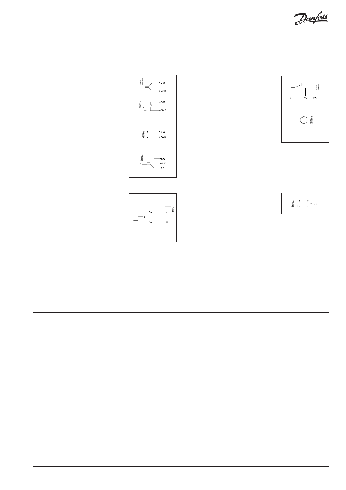
Connections
In principle there are the following types of connections:
Analog inputs ”AI”
This signal must be connected to two
terminals.
Signals can be received from the following
sources:
• Temperature signal from Pt 1000 ohm
temperature sensor
• Contact signal where the input is shortcircuited or ”opened”, respectively
• Voltage signal from 0 to 10 V
• Signal from pressure transmitter AKS 32,
AKS 32R or AKS 2050
The supply voltage is supplied from the
module’s terminal board where there is
both a 5 V supply and a 12 V supply.
When programming the pressure
transmitter’s pressure range must be set.
ON/OFF voltage inputs ”DI”
This signal must be connected to two
terminals.
• The signal must have two levels, either 0 V
or ”voltage” on the input.
There are two dierent extension
modules for this signal type:
- low-voltage signals, e.g. 24 V
- high-voltage signals, e.g. 230 V
ON/OFF output signals ”DO”
There are two types, as follows:
• Relay outputs
All relay outputs are with change-over
relay so that the required function can be
obtained when the controller is without
voltage.
• Solid state outputs
Reserved for AKV valves, but output can
cut an external relay in and out, as with a
relay output.
The output is only found on the
controller module.
When programming the function must be set:
• Active when the output is activated
• Active when the output is not activated.
Analog output signal ”AO”
This signal is to be used if a control signal is
to be transmitted to an external unit, e.g. a
frequency converter.
When programming the signal range must
be dened: 0-5 V, 1-5 V,
0-10 V or 2-10 V.
When programming the function must be set:
• Active when the input is without voltage
• Active when voltage is applied to the
input.
Limitations
As the system is very exible regarding the number of connected
units you must check whether your selection complies with the
few limitations there are.
The complexity of the controller is determined by the software,
the size of the processor, and the size of the memory. It provides
the controller with a certain number of connections from which
data can be downloaded, and others where coupling with relays
can be performed.
✔ The sum of connections cannot exceed 80.
✔ The number of extension modules must be limited so that the
total power will not exceed 32 VA (including controller).
✔ No more than 5 pressure transmitters may be connected to one
controller module.
✔ No more than 5 pressure transmitters may be connected to one
extension module.
Common pressure transmitter
If several controllers receive a signal from the same pressure transmitter, the supply to the aected controllers must be wired so that
it is not possible to switch o one of the controllers without also
switching o the others. (If one controller is switched o, the signal will be pulled down, and all the other controllers will receive a
signal which is too low)
AK-CH 650 Capacity controller RS8ER302 © Danfoss 2016-02 29
Page 30
Design of a compressor and condenser control
Procedure:
1. Make a sketch of the system in question
2. Check that the controller’s functions cover the required application
3. Consider the connections to be made
4. Use the planning table. / Note down the number of connections
./ add up
5. Are there enough connections on the controller module? – If
not, can they be obtained by changing an ON/OFF input signal
from voltage signal to contact signal, or will an extension module be required?
6. Decide which extension modules are to be used
7. Check that the limitations are observed
8. Calculate the total length of modules
8. The modules are linked together
10. The connection sites are established
11. Draw a connection diagram or a key diagram
12. Size of supply voltage/transformer
Follow these 12
steps
1
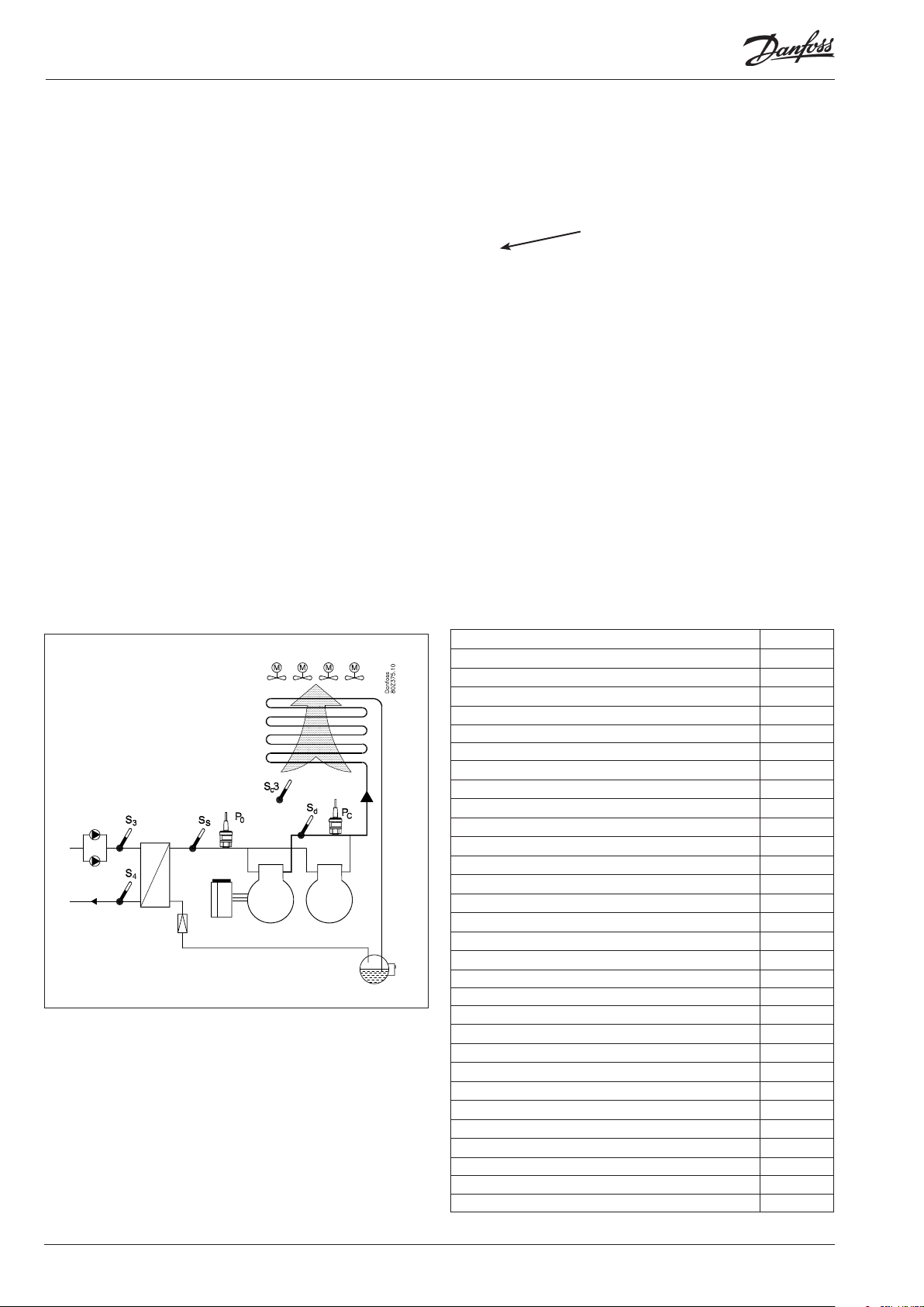
Sketch
Make a sketch of the actual plant.
2
Compressor and condenser functions
AK-CH 650
Application
Regulation of a compressor group x
Regulation of a condenser group x
Both compressor group and condenser group x
Pumpe control x
Regulation of compressor capacity
PI-regulation x
Max. number of compressors 6
Max. number of unloaders each compressor 3
Identical compressor capacities x
Dierent compressor capacities x
Sequentiel operation (rst in / last out) x
Speed regulation of 1 or 2 compressors x
Run time equalisation x
Min. restart time x
Min. On-time x
Liquid injection in heat exchanger x
Liquid injection in suction line x
Load shedding (Capacity limitation) x
Relay output, which is activated by a request for extra cooling x
0-10 V signal, which shows cutin compressor capacity x
Brine temperature reference
Override via P0 optimisation x
Override via “night setback” x
Override via "0 -10 V signal" x
Regulation of condenser capacity
Step regulation x
30 Capacity controller RS8ER302 © Danfoss 2016-02 AK-CH 650
Page 31

Max. number of steps 8
Speed regulation x
Step and speed regulation x
Speed regulation on rst step x
Limitation of speed during night operation x
Heat recovery function via thermostat function x
Heat recovery function via DI signal x
Trouble-shooting function FDD on condenser x
Condenser pressure reference
Floating condensing pressure reference x
Setting of reference for heat recovery function x
Safety functions
Min. suction pressure x
Max. suction pressure x
Max. condensing pressure x
Max. discharge gas temperature x
Min. / Max. superheat x
Safety monitoring of compressors x
Common high pressure monitoring of compressors x
Safety monitoring of condenser fans x
General alarm functions with time delay 10
Frost protection x
A bit more abot the functions
Compressor
Regulation of up to 6 compressors. Up to three unloaders per
compressor. Compressor No. 1 or 2 can be speed-regulated.
Condenser
Regulation of up to 8 condenser steps.
Fans can be speed-regulated. Either all on one signal or only the
rst fan of several.
Relay outputs and solid state outputs may be used, as desired.
Speed regulation of condenser fans
The function requires an analog output module.
A relay output may be used for start/stop of the speed regulation.
The fans may also be cut in and out by relay outputs.
Safety circuit
If signals are to be received from one or more parts of a safety
circuit, each signal must be connected to an ON/OFF input.
Day/night signal for raising the suction pressure
The clock function can be used, but an external ON/OFF signal
may be used instead.
If the “PO optimisation” function is used, no signal will be
given concerning the raising of the suction pressure. The PO
optimisation will see to this.
Miscellaneous
Extra sensors 7
Option for connection of separate display 2
Separate thermostat functions 5
Separate pressostat functions 5
Separate voltage measurements 5
3
Connections
Here is a survey of the possible connections. The texts can be read
in context with the table in point 4.
Analog inputs
Temperature sensors
• S4 and S3 (brine temperature)
Must always be used in connection with compressor regulation.
• Ss (suction gas temperature)
Must always be used in connection with compressor regulation.
• Sd (discharge gas temperature)
Must always be used in connection with compressor regulation.
• Sc3 (outdoor temperature)
To be used when monitoring function FDD is used.
To be used when regulation is performed with oating
condenser reference.
Separate thermostat and pressure control functions
A number of thermostats can be used according to your wishes.
The function requires a sensor signal and a relay output. In the
controller there are settings for cutin and cutout values. An associated alarm function may also be used.
Separate voltage measurements
A number of voltage measurements can be used according to
your wishes. The signal can for example be 0-10 V. The function
requires a voltage signal and a relay output. In the controller there
are settings for cutin and cutout values. An associated alarm function may also be used.
If you want to know more about the functions, go to
chapter 5.
• S7 (Hot brine return temperature))
This must be used when the control sensor for the condenser
has been selected as S7.
• Saux (1-4), Extra temperature sensors, if applicable
Up to four additional sensors for monitoring and data collection
may be connected.
These sensors can be used for general thermostat functions.
• Shrec (heat recovery thermostat)
Must be used when heat recovery is controlled via a thermostat
function.
AK-CH 650 Capacity controller RS8ER302 © Danfoss 2016-02 31
Page 32

Pressure transmitters
• P0 Suction Pressure
Must always be used in connection with compressor regulation
(frost protection)
• Pc Condensing Pressure
Must always be used in connection with compressor and condenser regulation
• Paux (1-3)
Up to 3 extra pressure transmitters can be connected for monitoring and data collection.
These sensors can be used for general pressure switch functions.
A pressure transmitter type AKS 32 or AKS 32R can supply signals
to a maximum of ve controllers.
Voltage signal
• Ext. reference
Used when overriding signal is received from another control.
• Volt indputs (1-5)
Up to 5 extra voltage signals can be connected for monitoring
and data collection. These signals can be used for general voltage input functions.
On/O-inputs
Contact function (on an analog input) or voltage signal (on an
extension module)
• Frost protection
• Flow switch or pressure dierence for pump monitoring
• Start of defrost
• Up to 6 signals from each compressors safety circuits
• Signal from the condenser fans’ safety circuit
• Any signal from the frequency converter’s safety circuit (comp.
and/or fans)
• External start/stop of regulation
• External start stop of heat recovery
• Up to 2 Inputs for capacity limitaiton
• External day/night signal (raise/lower the suction pressure reference). The function is not used if the “P0 optimisation” function
is used.
• DI alarm (1-10) inputs.
Up to 10 extra on/o signals for general alarm monitoring and
data collection can be connected.
On/o-outputs
Relay outputs
• Compressors (1-6)
• Unloaders (max. 3/compressor)
• Request extra cooling capacity
• Fan motor (1-8)
• Start/stop of liquid injection in heat exchanger
• Defrost output
• Start/stop of liquid injection in suction line
• Start/stop of heat recovery
• Start/stop of twin pumps (1-2)
• Start/stop of speed control (1-2) (comp. / fans)
• Alarm relay
• General functions from thermostats (1-5), pressostats (1-5) and
voltage inputs (1-5).
Solid state outputs
The solid state outputs on the controller module may be used
for the same functions as those mentioned under “relay outputs”.
(The output will always be “OFF” when the controller has a power
failure).
Analog output
• Speed regulation of the condenser’s fans.
• Speed regulation of compressor.
• Signal cutin compressor capacity.
Example
Compressor groupe:
• Refrigerant R404A
• 1 only speed-regulated compressor (30 kW, 30-60 Hz)
• 3 only compressors (15 kW) with working-hour equalisation
• Safety monitoring of each compressor + frequency converter
• Capacity limitation of compressors via contact signal (load shedding)
• Injection signal to heat exchanger
• Frost protection input (230 V a.c.)
• S4 setting 2°C
Air cooled condenser:
• 4 fans, step regulation
• Pc regulates based on outdoor temperature sensor Sc3
Pumps + defrost:
• start/stop of 2 pumps
• Monitoring via ow switch (contact signal)
• Output for defrost
Receiver:
• Monitoring of liquid level (230 V a.c.)
Fan in plant room
• Thermostat control of fan in engine room (sensor + output)
Safety functions:
• Monitoring of P0, Pc, Sd and superheat in suction line
• P0 min. = -10°C
• Pc max. = 50°C
• Sd max. = 120°C
• SH min. = 5°C, SH max. = 35°C
Other:
• Alarm output used
• External main switch used (contact signal)
Data from this example is used on the next page.
The result is that the following modules should be used:
• AK-CH 650 basic module
• AK-XM 102A digital input module
• AK-XM 204B relay module
• AK-OB 110 analog output module
32 Capacity controller RS8ER302 © Danfoss 2016-02 AK-CH 650
Page 33

Planning table
4
The table helps you establish whether there are enough
inputs and outputs on the basic controller.
If there are not enough of them, the controller must be
extended by one or more of the mentioned extension
modules.
Note down the connections you will require and add
them up
Analog inputs
Temperature sensors, S3, S4, S7 2
Temperature sensors, Ss, Sd 2
Outdoor temperature sensor, Sc3 1
Extra temperature sensor / separate thermostats
Pressure transmitters, P0, Pc, separate pressostats
0-10 V signal from other regulation, separate signals
Heat recovery via thermostat
On/o inputs
Safety circuits, frost protection
Safety circuits, Oil pressure
Safety circuits, comp. Motor protection /Motor temp.
Safety circuits, comp. High pres. thermostat
Safety circuits, comp. High pres. pressostat
Safety circuits, general for each compressor
Safety circuits, condenser fans
Safety circuits, frequency converter, comp. / cond.
Defrost start
External start/stop 1
Night setback of suction pressure
Flow switch
Separate alarm functions
Heat recovery via DI
Capacity limitations 1
On/o outputs
Compressors (motors) (extra capacity)
Unloaders
Fan motors
Alarm relay
Pumps
Defrost output
Separate thermostat and pressostat functions and voltage
measurements
Heat recovery function
Liquid injection in suction line and heat exchanger 1
Analog control signal, 0-10 V
Frequency converter compressor / condenser 1
Signal cutin compressor capacity
Sum of connections for the regulation
Number of connections on a controller module
Missing connections, if applicable
5
Analog input signal
Example
On/o voltage signal
Example
On/o voltage signal
Example
On/O output signal
Example
Analog output signal 0-10 V
Example
1
2 P = Max. 5 / module
contact 24 V 230 V
1
4
1
1 1
4
4
1
2
1
1
11 0 7 14 1 Sum = max. 80
11 11 0 0 0 0 8 8 0 0
- - 7 6 1
7
Limitations
The example:
None of the 3 limitations are exceeded => OK
The missing connections to be supplied by one or more extension modules:
6
AK-XM 101A (8 analog inputs)
AK-XM 102A (8 digital low voltage inputs)
AK-XM 102B (8 digital high voltage outputs)
AK-XM 103A (4 analog inputs 4 analog outputs) ___ pcs. á 2 VA = __
AK-XM 204A / B (8 relay outputs)
AK-XM 205A / B (8 analog inputs + 8 relay outp.)
AK_OB 110 (2 analog outputs)
1
1
Sum of power
___ pcs. á 2 VA = __
___ pcs. á 2 VA = __
___ pcs. á 2 VA = __
___ pcs. á 5 VA = __
___ pcs. á 5 VA = __
___ pcs. á 0 VA = 0
1
1 pcs. á 8 VA = 8
Sum =
Sum = max. 32 VA
AK-CH 650 Capacity controller RS8ER302 © Danfoss 2016-02 33
Page 34

8
Length
If you use many extension modules the controller’s length will
grow accordingly. The row of modules is a complete unit which
cannot be broken.
The module dimension is 72 mm.
Modules in the 100-series consist of one module
Modules in the 200-series consist of two modules
The controller consist of three modules
The length of an aggregate unit = n x 72 + 8
or in an other way:
Module Type Number at Length
Controller module 1 x 224 = 224 mm
Extension module 200-series _ x 144 = ___ mm
Extension module 100-series _ x 72 = ___ mm
Total length = ___ mm
9
Linking of modules
Start with the controller module and then mount the selected
extension modules. The sequence is of no importance.
However, you must not change the sequence, i.e. rearrange the
modules, after you have made the setup where the controller
is told which connections are found on which modules and on
which terminals.
The modules are attached to one another and kept together by a
connection which at the same time transmits the supply voltage
and the internal data communication to the next module.
Example continued:
Controller module + 1 extension module in 200-series + 1 extension
module in 100-series =
224 + 144 + 72 = 440 mm.
Mounting and removal must always be performed when there is
no voltage.
The protective cap mounted on the controller’s plug connection
must be moved to the last vacant plug connection so that the
plug will be protected against short-circuit and dirt.
When the regulation has started the controller will all the time
check whether there is connection to the connected modules. This
status can be followed by the light-emitting diode.
When the two catches for the DIN rail mounting are in open
position the module can be pushed into place on the DIN rail – no
matter where in the row the module is found.
Removal is likewise carried out with the two catches in the open
position.
34 Capacity controller RS8ER302 © Danfoss 2016-02 AK-CH 650
Page 35

10
Determine the connection points
All connections must be programmed with module and point, so
in principle it does not matter where the connections are made, as
long as it takes place on a correct type of input or output.
• The controller is the rst module, the next one is 2, etc.
• A point is the two or three terminals belonging to an input or
output (e.g. two terminals for a sensor and three terminals for a
relay).
The preparation of the connection diagram and the subsequent
programming (conguration) should take place at the present
time. It is most easily accomplished by lling in the connection
survey for the relevant modules.
Principle:
Name On module On Point Function
fx Compressor 1 x x Close
fx Compressor 2 x x Close
fx Alarm relay x x NC
fx Main switch x x Close
fx P0 x x AKS 32R 1-6 bar
The connection survey from the controller and any extension
modules are uploaded from the paragraph "Module survey. E.g.
controller module:
Signal Module Point Terminal
1 (AI 1) 1 - 2
2 (AI 2) 3 - 4
3 (AI 3) 5 - 6
4 (AI 4) 7 - 8
- Columns 1, 2, 3 and 5 are used for the programming.
- Columns 2 and 4 are used for the connection diagram.
Signal type /
Active at
module Point
Mind the numbering.
The right-hand part of the
controller module may look like
a separate module. But it isn’t.
Hint
In appendix B, 16 general installation types are illustrated.
If your installation is nearly similar to one of those illustrated, you can advantageously use the given connection
points.
Example continued:
Signal Module Point Terminal
Brine return temperature S3
Brinef supply temperature S4
Capacity limitation
Pump ow switch
Thermostat sensor in plant
room - Saux1
External main switch
Outdoor temperature - Sc3
Discharge temperature - Sd
Suction gas temperature- Ss
Suction pressure - P0
Condensing pressure - Pc
Compressor 1 / VSD
Compressor 2
Compressor 3
Compressor 4
Liq. injec. in heat exchanger
Pump 1
Pump 2
Speed control of compressor
1 (AI 1) 1 - 2
2 (AI 2) 3 - 4
3 (AI 3) 5 - 6
4 (AI 4) 7 - 8
5 (AI 5) 9 - 10
6 (AI 6) 11 - 12
7 (AI 7) 13 - 14
8 (AI 8) 19 - 20
9 (AI 9) 21 - 22
10 (AI 10) 23 - 24
1
11 (AI 11) 25 - 26
12 (DO 1) 31 - 32
13 (DO 2) 33 - 34
14 (DO 3) 35 - 36
15 (DO 4) 37 - 38
16 (DO 5) 39-40-41
17 (DO6) 42-43-44
18 (DO7) 45-46-47
19 (DO8) 48-49-50
24 -
25 -
Signal type /
Active at
Pt 1000
Pt 1000
Sluttet
Åben
Pt 1000
Sluttet
Pt 1000
Pt 1000
Pt 1000
AKS32-12
AKS32-34
ON
ON
ON
ON
ON
ON
ON
0-10 V
Signal
Fan 1
Fan 2
Fan 3
Fan 4
Defrost
Fan in plant room
Alarm
Mod-
ule
2
Point Terminal Active at
1 (DO 1) 25-26-27
2 (DO 2) 28-29-30
3 (DO 3) 31-32-33
4 (DO 4) 34-35-36
5 (DO 5) 37-38-39
6 (DO 6) 40-41-42
7 (DO 7) 43-44-45
On
On
On
On
On
On
O
8 (DO 8) 46-47-48
Signal Module Point Terminal Active at
Compressor 1 Gen. Safety
Compressor 2 Gen. Safety 2 (DI 2) 3 - 4 Open
Compressor 3 Gen. Safety 3 (DI 3) 5 - 6 Open
Compressor 4 Gen. Safety 4 (DI 4) 7 - 8 Open
VSD, compressor speed 5 (DI 5) 9 - 10 Open
Frost protection 6 (DI 6) 11 - 12 Open
DI alarm, Receiver level 7 (DI 7) 13 - 14 Open
1 (DI 1) 1 - 2 Open
3
8 (DI 8) 15 - 16
AK-CH 650 Capacity controller RS8ER302 © Danfoss 2016-02 35
Page 36

11
Connection diagram
Drawings of the individual modules may be
ordered from Danfoss.
Format = dwg and dxf.
You may then yourself write the module
number in the circle and draw the individual
connections.
Example continued:
Comp. 1 Gen. safety
Pump ow switch
Consumption limitation
1
exchanger
Frequency converter
Liquid injection in heat
2
Room fan
Comp. 3 Gen. safety
Comp. 2 Gen. safety
3
Frost protection
Receiver level alarm
VSD compressor speed
Comp. 4 Gen. safety
36 Capacity controller RS8ER302 © Danfoss 2016-02 AK-CH 650
Page 37

12
Supply voltage
Supply voltage is only connected to the controller module. The
supply to the other modules is transmitted via the plug between
the modules. The supply must be 24 V +/-20%. One transformer
must be used for each controller. The transformer must be a class
II. The 24 V must not be shared by other controllers or units. The
analog inputs and outputs are not galvanically separated from the
supply.
The + and – 24V input must not be earthed.
Example continued:
Controller module 8 VA
+ 1 extension module in 200-series 5 VA
+ 1 extension module in 100-series 2 VA
------
Transformer size (least) 15 VA
Transformer size
The power consumption grows with the number of modules used:
Module Type Number á Eect
Controller 1 x 8 = 8 VA
Extension module 200-series _ x 5 = __ VA
Extension module 100-series _ x 2 = __ VA
Total ___ VA
Common pressure transmitter
If several controllers receive a signal from the same pressure transmitter, the supply to the aected controllers must be wired so that
it is not possible to switch o one of the controllers without also
switching o the others. (If one controller is switched o, the signal will be pulled down, and all the other controllers will receive a
signal which is too low)
AK-CH 650 Capacity controller RS8ER302 © Danfoss 2016-02 37
Page 38

Ordering
1. Controller
Type Function Application Language Code no.
English, German, French,
AK-CH 650
Controller for capacity control of compressors
and condensers
Water chiller control
Dutch, Italian, Spanish,
Portuguese, Danish, Swedish,
Finnish, Russian, Czech, Polish,
Chinese
080Z0132
2. Extension modules and survey for inputs and outputs
Type Analog
inputs
For sensors,
pressure
transmitters
etc.
Controller 11 4 4 - - - - -
Extension modules
AK-XM 101A 8 080Z0007
AK-XM 102A 8 080Z0008 x
AK-XM 102B 8 080Z0013
AK-XM 103A 4 4 080Z0032
AK-XM 204A 8 080Z0011
AK-XM 204B 8 x 080Z0018 x
AK-XM 205A 8 8 080Z0010
AK-XM 205B 8 8 x 080Z0017
The following extension module can be placed on the PC board in the controller module.
There is only room for one module.
AK-OB 110 2 080Z0251 x
On/O outputs On/o supply voltage
Relay
(SPDT)
Solid state Low voltage
(DI signal)
(max. 80 V)
High voltage
(max. 260 V)
Analog
outputs
0-10 V d.c. For over-
module with
switches
ride of relay
outputs
Code no.
With screw
terminals
continued
continued
Example
x
Example
3. AK operation and accessories
Type Function Application Code no.
Operation
AK-ST 500 Software for operation of AK controllers AK-operation 080Z0161 x
- Cable between PC and AK controller AK - Com port 080Z0262 x
-
- Cable set + converter between PC and AK controller AK - USB 080Z0264
Accessories Power supply module 230 V / 115 V to 24 V
AK-PS 075 18 VA
AK-PS 150 36 VA 080Z0054
Accessories External display that can be connected to the controller module. For showing, say, the suction pressure
EKA 163B Display 084B8574
EKA 164B Display with operation buttons 084B8575
- Cable between display and controller
Accessories Real time clock for use in controllers that require a clock function, but are not wired with data communication.
AK-OB 101A Real time clock with battery backup. To be mounted in an AK controller 080Z0252
Cable between zero modem cable and AK controller /
Cable between PDA cable and AK controller
AK - RS 232 080Z0261
Supply for controller
Length = 2 m 084B7298
Length = 6 m 084B7299
080Z0053 x
Example
continued
38 Capacity controller RS8ER302 © Danfoss 2016-02 AK-CH 650
Page 39

3. Mounting and wiring
This section describes how the controller:
• Is tted
• Is connected
We have decided to work on the basis of the example we went
through previously, i.e. the following modules:
• AK-CH 650 controller module
• AK-XM 204B relay module
• AK-XM 102B digital input module
• AK-OB 110 analog output module
AK-CH 650 Capacity controller RS8ER302 © Danfoss 2016-02 39
Page 40

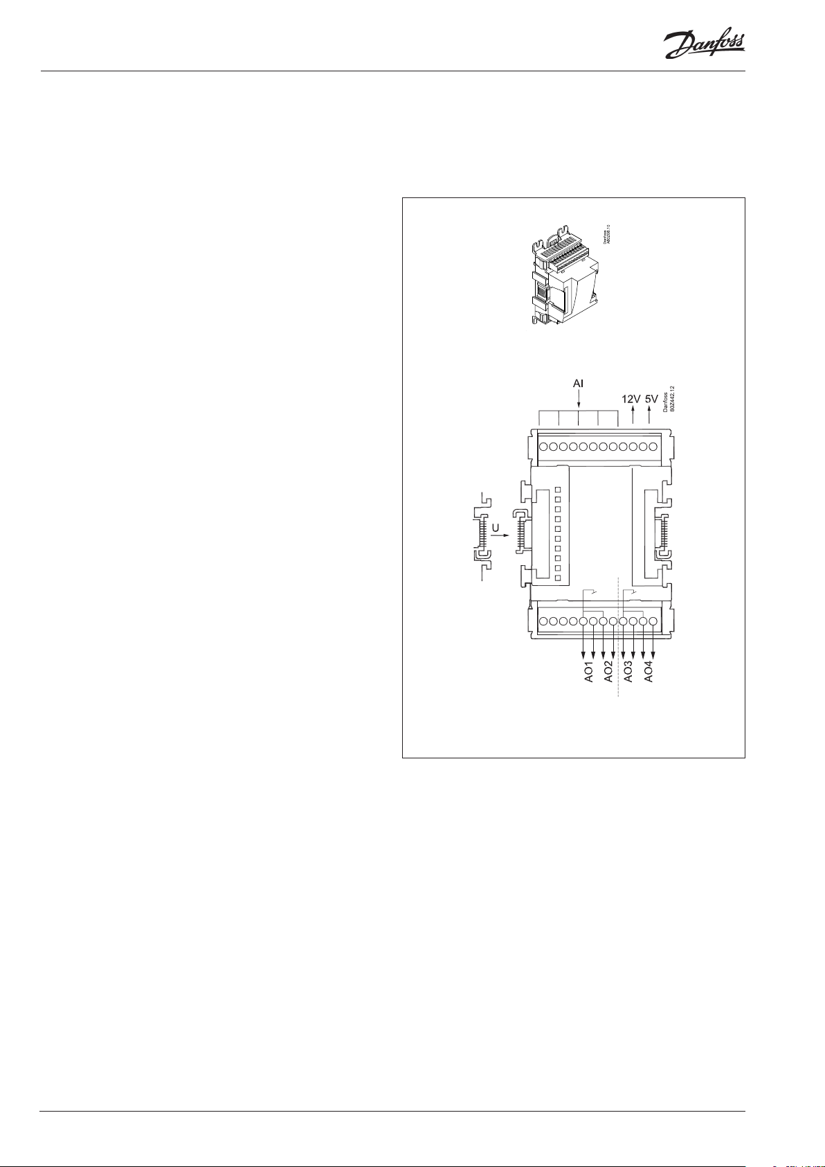
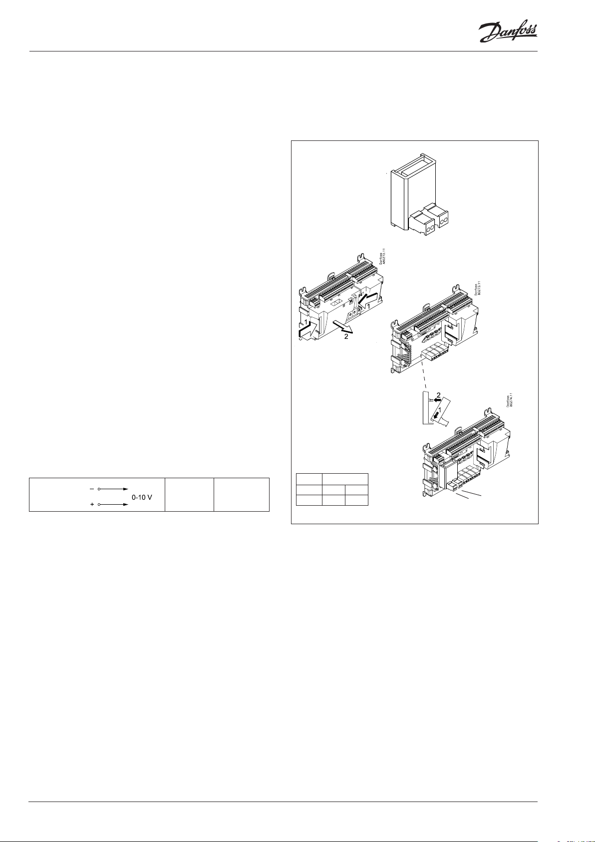
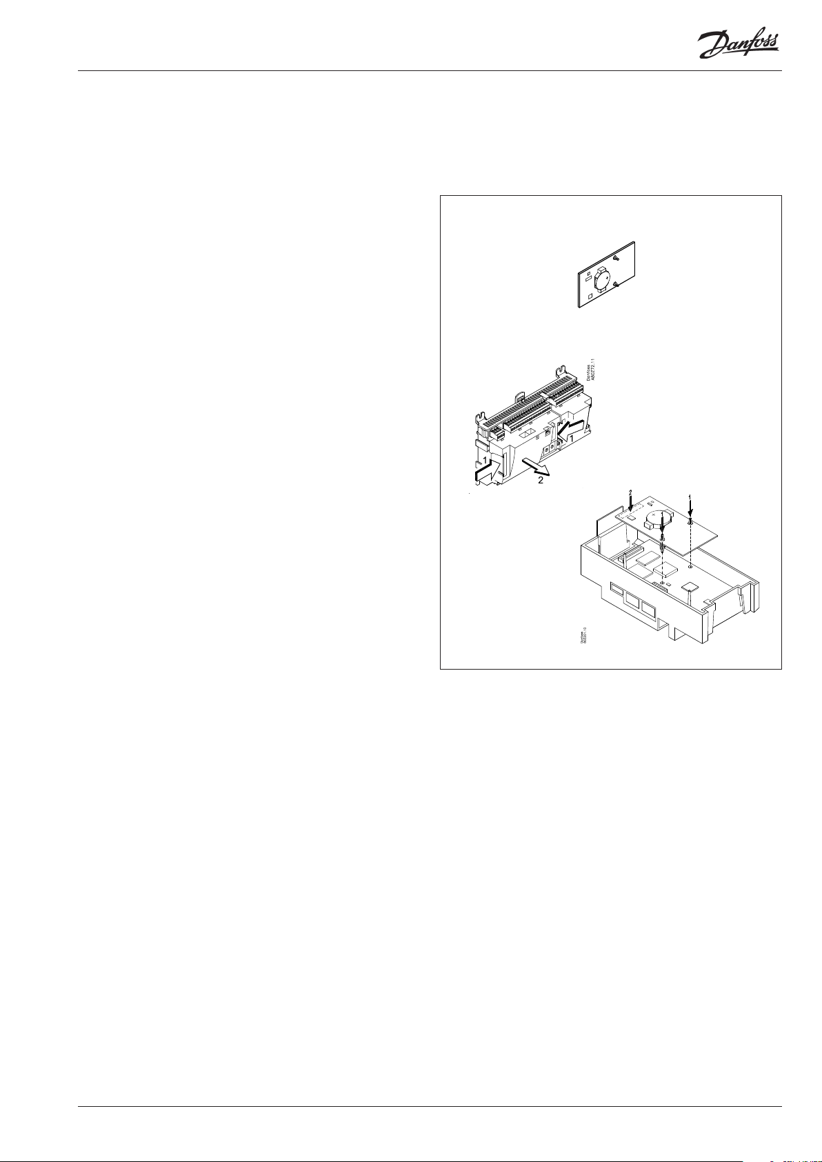
Mounting
Mounting of analog output module
1. Lift the top part o the basic module
The basic module must not be connected to voltage.
Press in the plate on the left-hand side of the light-emitting
diodes and the plate on the right-hand side for the red address
changers.
Lift the top part o the basic module.
The analog extension module will supply a signal to the variable frequency drive.
2. Mount the extension module in the basic module
3. Put the top part back on the basic module
There are two outputs, but we only use
one in the example.
40 Capacity controller RS8ER302 © Danfoss 2016-02 AK-CH 650
Page 41

Mounting and wiring - continued
Mounting of extension module on the basic module
1. Move the protective cap
Remove the protective cap from the connection plug on the
right-hand side of the basic module.
Place the cap on the connection plug to the right of the extension module that is to be mounted on the extreme right-hand
side of the AK assembly.
2. Assemble the extension module and the basic
module
The basic module must not be connected to voltage.
In our example two extension modules are to be tted to the basic
module. We have chosen to t the module with relays directly on the
basic module and then the module with input signals. The sequence is
thus:
3
All the subsequent settings that aect the two extension modules are
determined by this sequence.
When the two snap catches for the DIN rail mounting are in the open
position, the module can be pushed into place on the DIN rail – regardless of where the module is on the row.
Disassembly is thus done with the two snap catches in the open position.
AK-CH 650 Capacity controller RS8ER302 © Danfoss 2016-02 41
Page 42

Mounting and wiring - continued
Wiring
Decide during planning which function is to be connected and
where this will be.
1. Connect input and outputs
Here are the tables for the example:
Signal Module Point
Brine return temperature S3
Brine supply temperature S4
Consumption limitation
Pump ow switch
Thermostat sensor in plant
room - Saux1
External main switch
Outdoor temperature - Sc3
Discharge gas temperature - Sd
Suction gas temperature - Ss
Suction pressure - P0
Condenser pressure - Pc
Compressor 1 / VSD
Compressor 2
Compressor 3
Compressor 4
Liquid injec. in heat exchanger
Pump 1
Pump 2
Speed control of compressors
1 (AI 1) 1 - 2
2 (AI 2) 3 - 4
3 (AI 3) 5 - 6
4 (AI 4) 7 - 8
5 (AI 5) 9 - 10
6 (AI 6) 11 - 12
7 (AI 7) 13 - 14
8 (AI 8) 19 - 20
9 (AI 9) 21 - 22
10 (AI 10) 23 - 24
11 (AI 11) 25 - 26
1
12 (DO 1) 31 - 32
13 (DO 2) 33 - 34
14 (DO 3) 35 - 36
15 (DO 4) 37 - 38
16 (DO 5) 39-40-41
17 (DO6) 42-43-44
18 (DO7) 45-46-47
19 (DO8) 48-49-50
24 -
25 -
Terminal
Signal type /
Active at
Pt 1000
Pt 1000
Closed
Open
Pt 1000
Closed
Pt 1000
Pt 1000
Pt 1000
AKS32-12
AKS32-34
ON
ON
ON
ON
ON
ON
ON
0-10 V
The function of the switch functions can be seen in the last column.
There are AKS 32 pressure transmitters for several pressure ranges.
Here there are two dierent ones. One up to 12 bar and one up to 34 bar.
Signal Module Point Terminal Active at
Fan 1
Fan 2
Fan 3
Fan 4
Defrost
Fan in plant room
Alarm
1 (DO 1) 25-26-27
2 (DO 2) 28-29-30
3 (DO 3) 31-32-33
4 (DO 4) 34-35-36
2
5 (DO 5) 37-38-39
6 (DO 6) 40-41-42
7 (DO 7) 43-44-45
On
On
On
On
On
On
O
8 (DO 8) 46-47-48
Signal Module Point Terminal Active at
Compressor 1 Gen. safety
Compressor 2 Gen. safety 2 (DI 2) 3 - 4 Open
Compressor 3 Gen. safety 3 (DI 3) 5 - 6 Open
Compressor 4 Gen. safety 4 (DI 4) 7 - 8 Open
VSD, compressor speed 5 (DI 5) 9 - 10 Open
Frost protection 6 (DI 6) 11 - 12 Open
DI alarm, Receiver level 7 (DI 7) 13 - 14 Open
1 (DI 1) 1 - 2 Open
3
8 (DI 8) 15 - 16
42 Capacity controller RS8ER302 © Danfoss 2016-02 AK-CH 650
Page 43

Mounting and wiring - continued
The connections for the example can be seen
here.
Pumpe ow switch
Consumption limit
1
The screen on the pressure transmitter
cables must only be connected at the
end of the controller.
Warning
Keep signal cables separate from
cables with high voltage.
2
Comp. 1 Gen. safety
3
Comp. 3 Gen. safety
Comp. 2 Gen. safety
Comp. 4 Gen. safety
heat exchanger
Frequency converter
Liquid injection in
2. Connect LON communication network
The installation of the data communication must comply with
the requirements set out in document RC8AC.
3. Connect supply voltage
Is 24 V, and the supply must not be used by other controllers or
devices. The terminals must not be earthed.
4. Follow light-emitting diodes
When the supply voltage is connected the controller will go
through an internal check. The controller will be ready in just
under one minute when the light-emitting diode ”Status” starts
ashing slowly.
5. When there is a network
Set the address and activate the Service Pin.
Internal communication
between the modules:
Quick ash = error
Constantly On = error
■ Power
■ Comm
■ DO1 ■ Status
■ DO2 ■ Service Tool
■ DO3 ■ LON
■ DO4
■ DO5 ■ Alarm
■ DO6
■ DO7
■ DO8 ■ Service Pin
Status on output 1-8
Room Fan
Slow ash = OK
Quick ash = answer from gateway
in 10 min. after network
installation
Constantly ON = error
Constantly OFF = error
External communication
Flash = active alarm/not cancelled
Constant ON = Active alarm/cancelled
Network installation
Frost protection
Receiver level alarm
VSD compressorspeed
6. The controller is now ready to be congured.
AK-CH 650 Capacity controller RS8ER302 © Danfoss 2016-02 43
Page 44

44 Capacity controller RS8ER302 © Danfoss 2016-02 AK-CH 650
Page 45

4. Conguration and operation
This section describes how the controller:
• Is congured
• Is operated
We have decided to work on the basis of the example we went
through previously, i.e. compressor control with 4 compressors
and condenser control with 4 fans.
The example is shown overleaf.
AK-CH 650 Capacity controller RS8ER302 © Danfoss 2016-02 45
Page 46

Refrigerating plant example
We have decided to describe the setup by means of an example
comprising a compressor group and a condenser.
The example is the same as the one given in the "Design" section,
i.e. the controller is an AK-CH 650 + extension modules.
Compressor pack:
• Refrigerant R404A
• 1 only speed-regulated compressor (30 kW, 30-60 Hz)
• 3 only compressors (15 kW) with working-hour equalisation
• Safety monitoring of each compressor + frequency converter
• Capacity limitation of compressors via contact signal (load shedding)
• Injection signal to heat exchanger
• Frost protection input (230 V a.c.)
• S4 setting 2°C
Air cooled condenser:
• 4 fans, step regulation
• Pc regulates based on outdoor temperature Sc3
Pumps + defrost:
• Start/stop of 2 twin pumps
• Monitoring via ow switch (contact signal)
• Output for defrost
Receiver:
• Monitoring of liquid level (230 V a.c.)
Fan i plant room:
• Thermostat control of fan in plant room (sensor + output)
Safety functions:
• Monitoring of Po, Pc, Sd and superheat on suction line
• P0 min. = -10°C
• Pc max. = 50°C
• Sd max. = 120°C
• SH min. = 5°C, SH max = 35°C
Other:
• Alarm output used
• External main switch used
NB!
Not all the compressors can have their speed adjusted.
The capacity of the compressor with speed adjustment should be
greater than that of the other compressors.
This ensures that there are no "gaps" in the cut in capacity.
See chapter 5, Adjustment functions.
There is also an internal main switch as a setting. Both must be “ON”
before any adjustment is made.
The modules used are selected in the design phase.
For the example shown we use the following modules:
• AK-CH 650 basic module
• AK-XM 102B digital input module
• AK-XM 204B relay module
• AK-OB 110 analog output module
46 Capacity controller RS8ER302 © Danfoss 2016-02 AK-CH 650
Page 47

Conguration
Connect PC
PC with the program “Service Tool” is connected to the controller.
The controller must be switched on rst and the LED “Status” must
ash before the Service Tool programme is started.
Start Service Tool programme
For connecting and operating the "AK service tool" software,
please see the manual for the software.
The rst time the Service Tool is connected to a new version of a controller the start-up of the Service Tool will take longer than usual while
information is retrieved from the controller.
Time can be followed on the bar at the bottom of the display.
Login with user name SUPV
Select the name SUPV and key in the access code.
When the controller is supplied the SUPV access code is 123.
When you are logged into the controller an overview of it will always
appear.
In this case the overview is empty. This is because the controller has not
yet been set up.
The red alarm bell at the bottom right tells you that there is an active
alarm in the controller. In our case the alarm is due to the fact that the
time in the controller has not yet been set.
AK-CH 650 Capacity controller RS8ER302 © Danfoss 2016-02 47
Page 48

Conguration - continued
Authorization
1. Go to Conguration menu
Press the orange setup button with the spanner at the bottom
of the display.
2. Select Authorization
3. Change setting for the user ‘SUPV‘
When the controller is supplied it has been set with standard authorization for dierent user interfaces. This setting should be changed and
adapted to the plant. The changes can be made now or later.
You will use this button again and again whenever you want to get to
this display.
On the left-hand side are all the functions not shown yet. There will be
more here the further into the setup we go.
Press the line Authorization to get to the user setup display.
4. Select user name and access code
5. Carry out a new login with the user name and then
access code
Mark the line with the user name SUPV.
Press the button Change
This is where you can select the supervisor for the specic system and a
corresponding access code for this person.
In earlier versions of the service tool AK-ST 500 it was possible to select
the language in this menu.
An updated version of the service tool will be released in the spring of
2009. If the controller is operated with the new version, language selection will happen automatically in connection with the conguration of
the service tool.
The controller will utilize the same language that is selected in the
service tool but only if the controller contains this language. If the
language is not contained in the controller, the settings and readings
will be shown in English.
To activate the new settings you must carry out a new login to the controller with the new user name and the relevant access code.
You will access the login display by pressing the icon at the top left
corner of the display.
48 Capacity controller RS8ER302 © Danfoss 2016-02 AK-CH 650
Page 49

Conguration - continued
Unlock the conguration of the controllers
1. Go to Conguration menu
2. Select Lock/Unlock conguration
The controller can only be congured when it is unlocked.
It can only be adjusted when it is locked.
Changes to the input and output settings are only activated once the
controller is "Locked".
The values can be changed when it is locked, but only for those settings
that do not aect the conguration.
3. Select Conguration lock
Press the blue eld with the text Locked
4. Select Unlocked
AK-CH 650 Capacity controller RS8ER302 © Danfoss 2016-02 49
Page 50

Conguration - continued
System setup
1. Go to Conguration menu
2. Select System setup
All system settings can be changed by pressing in the blue eld with the
setting and then indicating the value of the required setting.
In the rst eld you enter a name for what the controller will be controlling.
When the time is set the PC’s time can be transferred to the controller.
When the controller is connected to a network, date and time will
automatically be set by the system unit in the network. This also applies
to change-over Daylight saving.
3. Set system settings
50 Capacity controller RS8ER302 © Danfoss 2016-02 AK-CH 650
Page 51

Conguration - continued
Set plant type
1. Go to Conguration menu
2. Select plant type
Press the line Select plant type.
3. Set plant type
When the installation
type is to be congured, it
can be done in two ways:
Either one of these two (we
chose to use the lowest).
The higher of the two settings gives
a choice between a number of pre-
dened combinations, which at the
same time determine the connec-
tion points.
At the end of the manual there is
an overview of the options and
connection points.
4. Set Common functions
In our example we want the
controller to control both
a compressor group and a
condenser group. We therefore
select the plant type One pack.
Further settings:
External main switch to Yes
Use Alarm output to High. (At ”High” the relay is only activated for
high-priority alarms).
The controller can transmit a 0-10 V signal that indicates how much
of the compressor capacity is cutin. We do not use this signal in the
example.
After conguration of this func-
tion, the controller will shut
down and restart. After the
restart, a large number of set-
tings will have been made.
These include the connec-
tion points. Continue with
the settings and check the
values.
If you change some of
the settings, the new
values will come into
force.
AK-CH 650 Capacity controller RS8ER302 © Danfoss 2016-02 51
Page 52

Conguration - continued
Set control of compressors
1. Go to Conguration menu
2. Select Suction group
3. Set values for the reference
Press the +-button to go on to the
next page
4. Set values for capacity control
The conguration menu in the
Service Tool has changed now. It
shows the possible settings for the
selected plant type.
In our example we select the
settings:
- Suction set point = -15°C
- Night oset value = 5 K.
The settings are shown here in the
display.
There are several pages, one after
the other.
The black bar in this eld tells you
which of the pages is currently
displayed.
Move between the pages using the
+ and - buttons.
In our example we select:
- 4 compressors
- P0 as signal to the regulation
- Refrigerant = R404A
- Equalisation of working hours
- Value for speed regulation
Speed regulation can always only
be on compressor number 1.
The settings are shown here in the
display.
Not all compressors can have their
speed adjusted. If there is any doubt,
contact your compressor supplier.
If you want to know more about the dierent conguration
options, they are listed below.
The number refers to the number and picture in the column
on the left.
3 - Reference mode
Displacement of suction pressure as a function of external
signals
0: Reference = set reference + night oset + oset from
external 0-10 V signal
1: Reference = set reference + oset from P0 optimization
+ Night displacement
Set point ( -80 to +30°C)
Setting of required suction pressure in °C
Oset via Ext. Ref
Select whether a 0-10V external reference override signal
is required
Oset at max input (-100 to +100 °C)
Displacement of reference at max. Ext. Ref. signal
Oset at min input (-100 to +100 °C)
Displacement of reference at min. Ext. Ref signal
Oset lter (10 - 1800 Sec)
Filter for displacement of reference, higher value results in
slower displacement
Night select via DI
Select whether a digital input is required for activation
of night operation. Night operation can alternatively be
controlled via internal weekly schedule or from the system
manager via data communication
Night Oset (-25 to +25 K)
Displacement of the brine temperature during night
operation (set in Kelvin)
Oset via S3
The reference selection must be displaced by a signal from
S3.
Tref S3 oset
Set the S3 temperature where it is not to be oset.
K1 S3 oset
Set the size of the change to be made in the reference
when the S3 temperature deviates 1 degree from the setting. (-10 to 10 K)
Max reference (-50 to +80 °C)
Max. permissible brine reference
Min reference (-80 to +25 °C)
Min. permissible brine reference.
4 - Compressor application
Select the compressor application required
No. of compressors
Set number of compressors
No. of unloaders
Set number of unloader valves
Regulation sensor
Select either P0 or S4
P0 Refrigerant
Select refrigerant type
Po refrigerant factors K1, K2, K3
Only used if “Po refrigerant type” is set to custom (contact
Danfoss for information)
Step control mode
Select coupling pattern for compressors
Sequential: Compressors are cut in/out in strict accordance
with compressor number (FILO)
Cyclic: Runtime equalisation between compressors (FIFO)
Best t: Compressors are cut in/out in order to make the
best possible t to actual load
Injection heat exchanger
If the function is selected, injection can be coordinated
with compressor operation in one of two ways:
Synchronisation: Simultaneously with compressor operation.
Pump down: Like synchronisation, but it is terminated with
pump down, where the valve is shut and the last compressor disengaged once "Pump down limit" is reached.
Pump down
Select whether a pump down function is required on the
last running compressor
52 Capacity controller RS8ER302 © Danfoss 2016-02 AK-CH 650
Page 53

Conguration - continued
Press the +-button to go on to the
next page
5. Set values for capacity of the
compressors
Press the +-button to go on to the
next page
6. Set values for main step and any
unloaders
Press the +-button to go on to the
next page
7. Set values for safe operation
In our example we select:
- Speed-controlled compressor of
30 kW (compressor 1)
- 3 compressors of 15 kW
In our example there are no
unloaders and hence no changes.
In our example we select:
- Safety limit for discharge
temperature = 120°C
- Safety limit for high condensing
pressure = 50°C
- Safety limit for low suction
pressure = -10°C
- Alarm limit for min. and max.
superheat, respectively = 5 and
35 K.
Pump down limit (-80 to +30 °C)
Select pump down limit
VSD min speed (0.5 – 60.0 Hz)
Minimum allowed speed before stop of Variable Speed drive
(Low load condition)
VSD start speed (20.0 – 60.0 Hz)
Minimum speed for start of Variable speed drive (Must be set
higher than “VSD Min. Speed Hz”)
VSD max speed (40.0 – 120.0 Hz)
Highest permissible speed for the compressor motor
VSD safety monitoring
Select this if input for monitoring of the frequency converter
is required.
Start delay rst compressor (5-600 sec.)
To ensure brine ow before startup, a delay before start of
the rst compressor can be entered.
Load shed limits
Select how many load shedding inputs are required
Load shed limit 1
Set max capacity limit for load shed input 1
Load shed limit 2
Set max capacity limit for load shed input 2
Override limit Po
Any load below the limit value is freely permitted. If the P0
exceeds the value, a time delay is started. If the time delay
expires, the load limit is cancelled
Override delay 1
Max. time for capacity limit, if P0 is too high
Override delay 2
Max. time for capacity limit, if P0 is too high
Advanced control settings
Select whether the advanced capacity control settings
should be visible
Kp S4
Amplication factor for P0 regulation (0.1 – 10.0)
Min. capacity change (0 – 100 %)
Minimum change in requested capacity that will result in cut
in/out of compressors.
Initial start time (15 – 900 s)
The time after start-up where the cut-in capacity is limited to
the rst compressor step.
Unloading mode
Select whether one or two capacity controlled compressors
are allowed to be unloaded at the same time at decreasing
capacity
5 - Compressors
In this screen the capacity distribution between the compressors is dened.
Capacities that need to be set depend upon the “compressor
application” and “Step control mode” that has been selected.
Nominal capacity (0.0 – 100000.0 kW)
Set the nominal capacity for the compressor in question.
For compressors with variable speed drive the nominal
capacity must be set for the mains frequency (50/60 Hz)
Unloader
Number of unload valves for each compressor (0-3)
6 - Capacity distribution
The installation is dependent on the combination of compressors and coupling pattern.
Main step
Set the nominal capacity of the main step (Set the percentage of the relevant compressor’s nominal capacity) 0 100%.
Unload
Readout of the capacity on every unloading 0-100%.
7 - Safety
Emergency cap. day
The desired cut-in capacity for daily use in the case of emergency operations resulting from error in the suction pressure
sensor/ media temperature sensor.
Emergency cap. night
The desired cut-in capacity for night operations in the case
of emergency operations resulting from error in the suction
pressure sensor/ media temperature sensor.
Sd max limit
Max. value for discharge gas temperature
10 K below the limit, the compressor capacity should be
AK-CH 650 Capacity controller RS8ER302 © Danfoss 2016-02 53
Page 54

Conguration - continued
Press the +-button to go on to the
next page
8. Set monitoring of compressor
Press the +-button to go on to the
next page
9. Set operation time for compressor
Press the +-button to go on to the
next page
10. Set times for safety cutouts
Press the +-button to go on to the
next page
11. Set Misc. function
Press the +-button to go on to the
next page
12. Setting pump functions
In our example we use:
- Frost protection
- One general safety monitoring
unit for each compressor
(The remaining options could
have been selected if specic
safety controls for each
compressor had been required)
Set min. OFF-time for the compressor relay
Set min. ON-time for the compressor relay
Set how often the compressor is
allowed to start
The settings only apply to the
relay that cuts the compressor
motor in and out.
They do not apply to unloaders.
If the restrictions overlap, the
controller will use the longest
restriction time.
In our example we do not use
these functions.
reduced and the entire condenser capacity will be cutin.
If the limit is exceeded, the entire compressor capacity will
be cutout
Pc Max limit
Maximum value for the condenser pressure in °C
3 K below the limit, the entire condenser capacity will be
cutin and the compressor capacity reduced.
If the limit is exceeded, the entire compressor capacity will
be cutout.
P0 Min limit
Minimum value for the suction pressure in °C
If the limit is reduced, the entire compressor capacity will be
cutout.
P0 min delay at start-up (0-600 sec)
Low pressure cut-out can be delayed for cut-out to be
avoided.
Safety restart time
Common time delay before restarting the compressor.
(Applicable to the functions: "Sd max. limit", Pc max. limit"
and "P0 min. limit).
SH Min alarm
Alarm limit for min. superheat in suction line.
SH Max alarm
Alarm limit for max. superheat in suction line.
SH alarm delay
Time delay before alarm for min./max. superheat in suction
line.
8 - Compressor safety
Frost protection
Choose whether an overall, joint security inlet for all compressors is desired. If the alarm is activated, all compressors
will be disengaged.
Oil pressure etc
Dene here whether this type of protection should be connected.
For "General", there is a signal from each compressor.
9 - Minimum operation times
Congure the operation times here so "unnecessary operation" can be avoided.
Restart time is the time interval between two consecutive
starts.
10 - Safety timer
Cutout delay
The time delay resulting from drop-out of automated safety
measures and until the compressor-error is reported. This
setting is common for all safety inputs for the relevant
compressor.
Restart delay
Minimum time that a compressor should be OK after a safety
cut-out. After this interval it can start again.
11 - Misc. functions
Alarm monitoring S4
Alarm option in the case of too high and too low S4
Dierent time delays are connected
Liq. inj suction line
Select the function if a liquid injection is required in the
suction line in order to keep the discharge gas temperature
down.
Extra cooling req.
The controller can activate a relay if it cannot keep the temperature down. The function has a temperature setting and
two delay times.
12 - Pumps
No of pumps (0, 1 or 2)
Cold pump control
Pump operation is dened here:
0: No pumps in operation
1: Only pump 1 in operation
2: Only pump 2 in operation
3: Both in operation
4: Operating time equalisation. Start before stop
5: Operating time equalisation. Stop before start
Pump cycle time
Operating time before changeover to the second pump
(1-500h)
Pump switch time
Overlapping time, where both pumps are in operation with
"start before stop" or break time with "stop before start"
(0-600 sec)
Pump safety
Select Common if monitored with ow switch
Select Individual if DI-signals are received from relays
Pump alarm delay
Delay from drop out to alarm.
54 Capacity controller RS8ER302 © Danfoss 2016-02 AK-CH 650
Page 55

Conguration - continued
Setup control of condenser
1. Go to Conguration menu
2. Select Condenser
3. Set control mode and reference
Press the +-button to go on to the
next page
4. Set values for capacity regulation
In our example the condenser
pressure is controlled on the
basis of the outdoor temperature
(oating reference).
The settings shown here in the
display.
Used in our example are four stepcontrolled fans.
The settings shown here in the
display.
For your information the function
”Monitor fan safety” will require an
input signal from each fan.
3 - PC reference
Control sensor
Pc: The condensing pressure PC is used for regulation
S7: Media temperature is used for regulation
Reference Mode
Choice of condenser pressure reference
Fixed setting: Used if a permanent reference is required =
“Setting”
Floating: Used if the reference is changed as a function of Sc3
the external temperature signal, the congured "Dimensioning tm K"/"Minimum tm K" and the actual cut in compressor
capacity.
Setpoint
Setting of desired condensing pressure in °C
Min. tm
Minimum average temperature dierence between Sc3 air
and Pc condensing temperature with no load.
Dimensioning tm
Dimensioning average temperature dierential between Sc3
air and Pc condensing temperature at maximum load (tm
dierence at max load, typically 8-15 K).
Min reference
Min. permitted condenser pressure reference
Max reference
Max. permitted condenser pressure reference
Heat recovery mode
Choice of method for heat recovery
No: Heat recovery not used
Thermostat: Heat recovery operated from thermostat
Digital input: Heat recovery operated from signal on a digital
input.
Heat recovery relay
Choose whether an output is required that should be activated during heat recovery.
Heat recovery ref
Reference for the condensing pressure, when heat recovery
is activated.
Heat recovery ramp down
Congure how quickly the reference for the condenser
pressure should be ramped down to normal level after heat
recovery. Congure in Kelvin per minute.
Heat recovery cutout
Temperature value where the thermostat cuts-out the heat
recovery.
Heat recovery cutin
Temperature value where the thermostat cuts-out the heat
recovery.
4 - Capacity control
Pc Refrigerant
Select refrigerant
Pc refrigerant factors K1, K2, K3
Only used if “Pc refrigerant type” is set to custom (contact
Danfoss for information)
No of fans
Set number of fans.
Monitoring fan safety
Safety monitoring of fans. A digital input is used to monitor
each fan.
Capacity control mode
Select control mode for condenser
Step: Fans are step-connected via relay outputs
Step/speed: The fan capacity is controlled via a combination
of speed control and step coupling
Speed: The fan capacity is controlled via speed control (frequency converter)
Speed control on rst step, rest=step
Control type
Choice of control strategy
P-band: The fan capacity is regulated via P-band control. The
P band is congured as "Proportional band Xp"
PI-Control: The fan capacity is regulated by the PI controller.
Capacity curve
Choice of capacity curve type
Linear: The same amplication in the entire area
Square: Square curve shape, which gives higher amplication
at higher loads.
AK-CH 650 Capacity controller RS8ER302 © Danfoss 2016-02 55
Page 56

Conguration - continued
Continued
VSD start speed
Minimum speed for start of speed control (Must be congured higher than
"VSD Min. Speed %")
VSD min Speed
Minimum speed whereby speed control is cut-out (low load).
Proportional band Xp
Proportional band for P/PI controller
Integration time Tn
Integration time for PI controller
VSD safety monit.
Choice of safety monitoring of frequency converter. A digital inlet is used
for monitoring the frequency converter.
Capacity limit at night
Setting of maximum capacity limit during night operations. Can be used
to limit fan speed at night in order to limit the noise level.
Monitor Air ow
Choose whether monitoring is required of the condenser's air ow via an
intelligent error-detection method.
Monitoring requires the use of a Sc3 outer temperature sensor, which
must be tted by the condenser's air inlet.
FDD setting
Set error-detection function
Tuning: The controller makes an adjustment to the condenser concerned.
Note that tuning should only be done when the condenser is operating
under normal operating conditions.
ON: Tuning is completed and monitoring has commenced.
OFF: Monitoring is cut out.
FDD sensitivity
Set the sensitivity of error-detection on the condenser’s air ow. Must only
be changed by trained sta.
Air ow tuning value
56 Capacity controller RS8ER302 © Danfoss 2016-02 AK-CH 650
Page 57

Conguration - continued
Setup Display
1. Go to Conguration menu
2. Select Display setup
3. Dene which readings are to be
shown for the individual outputs
3 - Display setup
Display
The following can be read for the four outputs..
Comp. control sensor
P0
P0 bar (abs)
S3
S4
Ss
Sd
Cond. control sensor
Pc
Pc Bar (abs)
S7
Unit readout
Choose whether readings are to be in SI units (°C and bar) or
(US-units °F and psi)
In our example, separate displays
are not used. The setting is
included here for information.
AK-CH 650 Capacity controller RS8ER302 © Danfoss 2016-02 57
Page 58

Conguration - continued
Setup defrost
1. Go to Conguration menu
2. Select Defrost
3. Dene the required defrost
functions
When no input is used to start a defrost
cycle, this allows use of a schedule where
the defrost startup times are specied.
The schedule is located under the daily user
interface. See page 72.
Actual tuning values for air ow.
3 - Defrost functions
Defrost function
Select whether defrost control is to be used
Defrost start via DI
Select whether a DI input to start the defrost
cycle is to be used. .
If not, this allows a defrost schedule to be attached to the "daily user interface"..
Defrost stop
Select a defrost stop procedure. By time. / By S3
temperature. By S4 temperature
Defrost stop temp.
Value setting (-5 to 60)
Max. defrost time
Max. permitted defrost time Refrigeration will
always start once this time has passed.
Drip delay
Time after defrost end, where the water is dripping from the refrigeration surfaces.
Defrost outputs
Select whether an output is to be activated during defrosting..
Comp.operation during defrost
Select whether the compressors are to run during defrosting.
58 Capacity controller RS8ER302 © Danfoss 2016-02 AK-CH 650
Page 59

Conguration - continued
Setup general alarm inputs
1. Go to Conguration menu
2. Select General alarm inputs
3. Dene the required
alarm functions
In our example we select one alarm function
for monitoring the liquid level in the receiver.
We have subsequently selected a name for the
alarm function and for the alarm text.
3 - General alarm input
This function can be used to monitor all kinds of
digital signals.
No. of inputs
Set the number of digital alarm inputs
Adjust for each input
• Name
• Delay time for DI alarm (common value for all)
• Alarm text
AK-CH 650 Capacity controller RS8ER302 © Danfoss 2016-02 59
Page 60

Conguration - continued
Setup separate thermostat functions
1. Go to Conguration menu
2. Select Thermostats
3. Dene the required thermostat
function
In our example we select one termostat
function for monitoring the plant room
temperature.
We have subsequently entered a name for the
function.
3 - Thermostats
The general thermostats can be used to monitor
the temperature sensors that are used, as well
as 4 extra temperature sensors. Each thermostat
has a separate outlet to control external automation.
No. of thermostats
Set the number of general thermostats.
For each thermostat adjust
• Name
• Which of the sensors is used
Actual temp.
Temperature measurement on the sensor that is
attached to the thermostat
Actual state
Actual status on the thermostat outlet
Cut out temp.
Cut-out value for the thermostat
Cut in temp.
Cut-in value for the thermostat
High alarm limit
High alarm limit
Alarm delay high
Time delay for high alarm
Alarm text high
Indicate alarm text for the high alarm
Low alarm limit
Low alarm limit
Alarm delay low
Time delay for low alarm
Alarm text low
Indicate alarm text for low alarm
3b - Pressostats
There are similar settings for up to 3 pressure
Via the +- button you can move to similar settings for the pressure control functions. (Not
used in the example)
switch functions.
60 Capacity controller RS8ER302 © Danfoss 2016-02 AK-CH 650
Page 61

Conguration - continued
Setup separate voltage functions
1. Go to Conguration menu
2. Select General Voltage inputs
(In our example we do not use this
function).
3. Dene the required names
and values attached to the
signal
In our example we do not use this function,
so the display has been included for your
information only.
The name of the function may be xx and
further down in the display the alarm texts
may be entered.
The values ”Min. and Max. Readout” are your
settings representing the lower and upper
values of the voltage range. 2V and 10V, for
example. (The voltage range is selected during
the I/O setup).
For each voltage input dened the controller
will reserve a relay output in the I/O setup.
It is not necessary to dene this relay if all
you require is an alarm message via the data
communication.
3 - Voltage inputs
The general volt inlet can be used to monitor
external voltage signals. Each volt inlet has a
separate outlet to control external automatic
controls.
No. of voltage inp.
Set the number of general voltage inputs,
specify 1-5:
Name
Actual value
= read-out of the measurement
Actual state
= read-out of outlet status
Min. readout
State read-out values at minimum voltage signal
Max. readout
State read-out values at maximum voltage signal
Cutout
Cut-out value for outlet
Cutin
Cut-in value for outlet
Cutout delay
Time delay for cut-out
Cut in delay
Time delay for cut-in
Limit alarm high
High alarm limit
Alarm delay high
Time delay for high alarm
Alarm text high
Set alarm text for high alarm
Limit alarm low
Low alarm limit
Alarm delay low
Time delay for low alarm
Alarm text low
Indicate alarm text for low alarm
AK-CH 650 Capacity controller RS8ER302 © Danfoss 2016-02 61
Page 62

Conguration - continued
Conguration of inputs
and outputs
1. Go to Conguration menu
2. Select I/O conguration
3. Conguration of Digital outputs
The following displays will depend on the earlier denitions. The
displays will show which connections the earlier settings will require.
The tables are the same as shown earlier.
• Digital outputs
• Digital inputs
• Analog outputs
• Analog inputs
Load Output Module Point Active at
Compressor 1 / VSD DO1 1 12 ON
Compressor 2 DO2 1 13 ON
Compressor 3 DO3 1 14 ON
Compressor 4 DO4 1 15 ON
DO5 1 16
Liq.injec. in heat exchanger
Pump 1 DO7 1 18 ON
Pump 2 DO8 1 19 ON
Fan 1 DO1 2 1 ON
Fan 2 DO2 2 2 ON
Fan 3 DO3 2 3 ON
Fan 4 DO4 2 4 ON
Defrost DO5 2 5 ON
Fan in plant room DO6 2 6 ON
Alarm DO7 2 7 OFF !!!
!!! The alarm is inverted so that there will be an alarm if the supply
voltage to the controller fails.
We set up the controller’s digital outputs by keying in which module
and point on this module each one of these has been connected to.
We furthermore select for each output whether the load is to be active
when the output is in pos. ON or OFF.
DO6 1 17 ON
DO8 2 8
3 - Outputs
The possible functions are
the following:
Comp. 1
Unloader 1-1, 1-2, 1-3
Comp. 2-6
Extra cooling
Cold pump 1
Cold pump 2
Injec. in suction line
Injec in heat exchanger
Defrost
Fan 1 / VSD
Fan 2 - 8
Hest recovery
Alarm
Thermostat 1 - 5
Pressostat 1 - 5
Voltage input 1 - 5
4 - Digital inputs
The possible functions are
the following:
Ext. Main switch
Night setback
Load shed 1
Load shed 2
Frost protection
All compressors:
Compressor. __
Oil pressure safety
Over current safety
Motor protect. safety
Disch. temp. safety
Disch. press. safety
General safety
VSD comp_. error 1-2
Flow switch (cold pump)
Cold pump 1 monitoring
Cold pump 2 monitoring
Fan 1 protection
Fan 2......8 protection
VSD Cond. protection
Heat recovery
DI Alarm 1
DI Alarm 2.....10
Defrost
Press the +-button to go on to the
next page
4. Setup On/o input functions
Press the +-button to go on to the
next page
Function Input Module Point Active at
Consumpt. limit AI3 1 3 Closed
Pump ow switch AI4 1 4 Open
External main switch AI6 1 6 Closed
Compressor 1 Gen. Safety DI1 3 1 Open
Compressor 2 Gen. Safety DI2 3 2 Open
Compressor 3 Gen. Safety DI3 3 3 Open
Compressor 4 Gen. Safety DI4 3 4 Open
VSD, comp. speed DI5 3 5 Open
Frost protection DI6 3 6 Open
Receiver level on/o DI7 3 7 Open
We set up the controller’s digital input functions by keying in which
module and point on this module each one of these has been connected
to.
We furthermore select for each output whether the function is to be active when the output is in pos. Closed or Open.
Open has been selected here for all the safety circuits. This means that
the controller will receive signal under normal operation and register it
as a fault if the signal is interrupted.
62 Capacity controller RS8ER302 © Danfoss 2016-02 AK-CH 650
Page 63

Conguration - continued
5. Conguration of Analog
outputs
Function Output Module Point Type
Speed control of compressor
We set up the analog outputs for control of the compressor speed.
AO1 1 24 0-10 V
5 - Analog outputs
The possible signals are the
following:
0 -10 V
2 – 10 V
0 -5 V
1 – 5V
Select for:
• Speed control comp.
• Speed control fans.
• Show cutin compressor
capacity
Press the +-button to go on to
the next page
6. Conguration of Analog
Input signals
Sensor Input Module Point Type
Brine return temp. S3 AI1 1 1 Pt 1000
Brine supply temp. S4 AI2 1 2 Pt 1000
Thermostat sensor in plant
room - Saux1
Outdoor temp. - Sc3 AI7 1 7 Pt 1000
Disch. gas temperature - Sd AI8 1 8 Pt 1000
Suction gas temperature
- Ss
Suction pressure - Po AI10 1 10 AKS32-12
Condenser pressure - Pc AI11 1 11 AKS32-34
We set up the analog inputs for the sensors.
AI5 1 5 Pt 1000
AI9 1 9 Pt 1000
6 - Analog inputs
The possible signals are the
following:
Temperature sensors:
• Pt1000
• PTC 1000
Pressure transmitters:
• AKS 32, -1 – 6 bar
• AKS 32R, -1 – 6 Bar
• AKS 32, - 1 – 9 Bar
• AKS 32R, -1 – 9 Bar
• AKS 32, - 1 – 12 Bar
• AKS 32R, -1 – 12 Bar
• AKS 32, - 1 – 20 Bar
• AKS 32R, -1 – 20 Bar
• AKS 32, - 1 – 34 Bar
• AKS 32R, -1 – 34 Bar
• AKS 32, - 1 – 50 Bar
• AKS 32R, -1 – 50 Bar
• AKS 2050, -1 – 59 Bar
• AKS 2050, -1 – 99 Bar
• AKS 2050, -1 – 159 Bar
• User dened (only ratiometric, min. and max value
of the pressure range must
be set)
Voltage signals for reference displacement:
• 0 – 5 V,
• 0 -10 V
S4 Brine supply
S3 Brine return
P0 suction pressure
Ss suction gas
Sd disch gas
Pc cond. press.
S7 warm brine
Sc3 air on
Ext. Ref. Signal
Heat recovery
Saux 1 - 4
Paux 1 - 3
Voltage input 1 - 5
• 0 -5 V,
• 0 -10 V,
• 1 – 5 V,
• 2 – 10 V
AK-CH 650 Capacity controller RS8ER302 © Danfoss 2016-02 63
Page 64

Conguration - continued
Set alarm priorities
1. Go to Conguration menu
2. Select Alarm priorities
3. Set priorities for Suction group
Very many functions have an alarm connected.
Your choice of functions and settings has connected all the relevant
alarms that are current. They will be shown with text in the three
pictures.
All alarms that can occur can be set for a given order of priority:
• ”High” is the most important one
• ”Log only” has lowest priority
• ”Disconnected” gives no action
The interdependence between setting and action can be seen in the
table.
Setting
High X X X X 1
Medium X X X 2
Low X X X 3
Log only X
Discon-
nected
See also alarm text
Log Alarm relays selection Net-
Non High Low - High
work
AKM dest.
Press the +-button to go on to the next page
4. Set alarm priorities for condenser
.
The rst alarms for the suction groups are shown here.
Further down in the display the priorities for the compressors’ safety
circuits are set.
In our example we select the settings shown here in the display
Press the +-button to go on to the next page
64 Capacity controller RS8ER302 © Danfoss 2016-02 AK-CH 650
Page 65

Conguration - continued
5. Set alarm priorities for thermostat and extra Digital
signals
In our example we select the settings shown here in the display
AK-CH 650 Capacity controller RS8ER302 © Danfoss 2016-02 65
Page 66

Conguration - continued
Lock conguration
1. Go to Conguration menu
2. Select Lock/Unlock conguration
3. Lock Conguration
The controller will now make a comparison of selected functions and dene inputs and outputs. The result can be seen in
the next section where the setup is controlled.
Press in the eld against Conguration lock.
Select Locked.
The setup of the controller has now been locked. If you subsequently
want to make any changes in the controller’s setup, remember rst to
unlock the conguration.
66 Capacity controller RS8ER302 © Danfoss 2016-02 AK-CH 650
Page 67

Conguration - continued
Check conguration
1. Go to Conguration menu
2. Select I/O conguration
3. Check conguration of Digital Outputs
Press the +-button to go on to the next page
4. Check conguration of Digital Inputs
This control requires that the setup is locked
(All input and output settings only become active once the
setup is locked.)
An error has occurred, if you see the following:
The setup of the digital
outputs appears as it is supposed to according to the
wiring made.
A 0 – 0 next to a dened function.
If a setting has reverted to 0-0, you must control
the setup again.
This may be due to the following:
• A selection has been made of a combination of
module number and point number that does
not exist.
• The selected point number on the selected module had been set up for something dierent.
The error is corrected by setting up the output
correctly.
Remember that the setup must be unlocked before you can change module and point numbers..
Press the +-button to go on to the next page
5. Check conguration of Analog Outputs
The setup of the digital
inputs appears as it is supposed to according to the
wiring made.
The settings are shown on a RED background.
If a setting has turned red, you must control the
setup again.
This may be due to the following:
• The input or the output has been set up; but the
setup has later been changed so that it should
no longer be applied.
The problem is corrected by setting module
number to 0 and point number to 0.
Remember that the setup must be unlocked before you can change module and point numbers.
Press the +-button to go on to the next page
AK-CH 650 Capacity controller RS8ER302 © Danfoss 2016-02 67
Page 68

Conguration - continued
6. Check conguration of Analog Inputs
68 Capacity controller RS8ER302 © Danfoss 2016-02 AK-CH 650
Page 69

Check of connections
1. Go to Conguration menu
2. Select I/O status and manual
3. Check Digital Outputs
Press the +-button to go on to the next page
Before the control is started we check that all inputs and outputs have
been connected as expected.
This controls requires that the setup is locked
By means of the manual control of each output it can be checked
whether the output has been correctly connected.
AUTO The output is controlled by the controller
MAN OFF The output is forced to pos. OFF
MAN ON The output is forced to pos ON
4. Check Digital Inputs
Press the +-button to go on to the next page
Cut out the safety circuit for compressor 1.
Check that LED DI1 on the extension module (module 3) goes out.
Check that the value of the alarm for the safety monitoring of compressor 1 changes to ON.
The remaining digital inputs are checked in the same way.
AK-CH 650 Capacity controller RS8ER302 © Danfoss 2016-02 69
Page 70

Check of connections - continued
5. Check Analog outputs
6. Put the control of the output voltage back to automatic
Set Control of output voltage to manual
Press in the Mode eld.
Select MAN.
Press in the Value eld
Select for example 50%.
Press OK.
On the output you can now measure the expected value: In this
example 5 volts
Example of the connection between a dened output signal
and a manual set value.
Denition Setting
0 % 50 % 100 %
0 - 10 V 0 V 5 V 10 V
1 - 10 V 1 V 5.5 V 10 V
0 - 5 V 0 V 2.5 V 5 V
2 - 5 V 2 V 3.5 V 5 V
Press the +-button to go on to the next page
7. Check Analog inputs
Check that all sensors show sensible values.
In our case we have no value for the most sensors. This may be due to
the following:
• The sensor has not been connected.
• The sensor is short-circuited.
• The point or module number has not been set up correctly.
• The conguration is not locked.
70 Capacity controller RS8ER302 © Danfoss 2016-02 AK-CH 650
Page 71

Check of settings
1. Go to the overview
2. Select suction group
Before the control starts, we check that all the settings are as they should
be.
The overview display will now show one line for each of the general
functions. Behind each icon there is a number of displays with the
dierent settings. It is all these settings that have to be checked.
3. Move on through all the individual displays for the
suction group
Change displays with the +- button. Remember the settings at
the bottom of the pages – the ones that can only be seen via
the ”Scroll bar”.
4. Safety limits
5. Go back to the overview
The last page contains safety limits and restart times.
6. Select condenser group
AK-CH 650 Capacity controller RS8ER302 © Danfoss 2016-02 71
Page 72

Check of settings - contiuned
7. Move on through all the individual displays for the
condenser group
Change displays with the +- button. Remember the settings at
the bottom of the pages – the ones that can only be seen via
the ”Scroll bar”.
8. Safety limits
The last page contains safety limits and restart times.
9. Go back to the overview and Move on to the defrost
function
Check the settings.
10. Go back to the overview and Move on to the thermostat group
Check the settings.
11. Go back to the overview and on to the general
alarm inputs
In the example, the defrost schedule has been set to two
defrosts a day.
Check the settings.
12. The controller setup has been completed.
72 Capacity controller RS8ER302 © Danfoss 2016-02 AK-CH 650
Page 73

Schedule function
1. Go to Conguration menu
2. Select schedule
3. Setup schedule
Before regulation is started we will set the schedule function for the
night setback of the suction pressure.
In other cases where the controller is installed in a network with one
system unit, this setting may be made in the system unit which will then
transmit a day/night signal to the controller.
Press a weekday and set the time for the day period.
Continue with the other days.
A complete weekly sequence is shown in the display.
AK-CH 650 Capacity controller RS8ER302 © Danfoss 2016-02 73
Page 74

Installation in network
1. Set the address (here, for example 3)
Turn the right-hand address switch so that the arrow will point
at 3.
The arrow of the two other address switches must point at 0.
2. Push the Service Pin
Press down the service pin and keep it down until the Service
Pin LED lights up.
The controller has to be remote-monitored via a network. In this network we assign address number 3 to the controller.
The same address must not be used by more than one controller in the
same network.
Requirement to the system unit
The system unit must be a gateway type AKA 245 with software version
6.0 or higher. It is capable of handling up to 119 AK controllers.
3. Wait for answer from the system unit
Depending on the size of the network it may be up to one
minute before the controller receives an answer as to whether
it has been installed in the network.
When it has been installed the Status LED will start to ash
faster than normal (once every half second). It will continue
with this for about 10 minutes
4. Carry out new login via Service Tool
If the Service Tool was connected to the controller while you
installed it in the network, you must carry out a new login to
the controller via the Service Tool.
If there is no answer from the system unit
If the Status LED does not start ashing faster than normal, the controller has not been installed in the network. The reason for this may be
one of the following:
The controller has been assigned an address out of range
Address 0 cannot be used.
If the system unit in the network is an AKA 243B Gateway only the ad-
dresses between 1 and 10 can be used.
The selected address is already being used by another controller or
unit in the network:
The address setting must be changed to another (vacant) address.
The wiring has not been carried out correctly.
The termination has not been carried out correctly.
The data communication requirements are described in the document:
”Data communication connections to ADAP-KOOL® Refrigeration Controls” RC8AC.
74 Capacity controller RS8ER302 © Danfoss 2016-02 AK-CH 650
Page 75

First start of control
Check alarms
1. Go to the overview
Press the blue overview button with the compressor and condenser at the bottom left of the display.
2. Go to the Alarm list
Press the blue button with the alarm bell at the bottom of the
display.
3. Check active alarms
4. Remove cancelled alarm from the alarm list
Press the cross to remove cancelled alarms from the alarm list.
5. Check active alarm again
In our case, we have a series of alarms. We will tidy them up so that we
only have those that are relevant.
In our case an active alarm remains because the control has stopped.
This alarm must be active when control has not started. We are now
ready for the startup of control.
Please note that active plant alarms are automatically cancelled when the
main switch is in pos. OFF.
If active alarms appear when the control is started the reason for these
should be found and remedied.
AK-CH 650 Capacity controller RS8ER302 © Danfoss 2016-02 75
Page 76

First start of control - continued
Start the control
1. Go to Start/Stop display
Press the blue manual control button at the bottom of the
display.
2. Start control
Press in the eld against Main switch.
Select ON.
The controller will now start controlling the compressors and the fans.
Note:
Control does not start until both the internal and external switch are
“ ON ”.
76 Capacity controller RS8ER302 © Danfoss 2016-02 AK-CH 650
Page 77

Manual capacity control
1. Go to overview
2. Select suction group
Press the suction group button for the suction group that is to
be controlled manually.
Press the +-button to go on to the next page
3. Set capacity control to manual
If you need to manually adjust the capacity of the compressors, you can
use the following procedure:
Press the blue eld against Control mode
Select MAN.
4. Set capacity in percent
Press in the blue eld against Manual capacity.
AK-CH 650 Capacity controller RS8ER302 © Danfoss 2016-02 77
Set the capacity to the required percentage.
Press OK.
Page 78

Manual defrost
1. Go to Conguration menu
2. Select defrost
3. Start defrost
If you want to perform a manual defrost, this can be done via the following operation.
78 Capacity controller RS8ER302 © Danfoss 2016-02 AK-CH 650
Page 79

5. Regulating functions
This section describes how the dierent functions work
AK-CH 650 Capacity controller RS8ER302 © Danfoss 2016-02 79
Page 80

Suction group
Capacity control of compressors
PI-control and control zones
AK-CH 650 can control up to 6 compressors with up to 3 unloader
valves each. One or two of the compressors can be equipped with
speed regulation.
The calculation of the requested compressor capacity takes place
on the basis of a PI control, but the set up is carried out in the
same way as for a neutral zone controller which is divided into 5
dierent control zones as shown in below sketch.
Brine temperature
The width of some of the zones can be set via the settings “+ Zone
K”, “NZ K” and “- Zone K”.
Furthermore it is possible to adjust zone timers which is equal to
the Tn integration time for the PI controller whenever the suction
pressure is in the zone in question (please see sketch above).
By setting a zone timer to a higher value will make the PI controller
slower in this zone and by setting the zone timer lower will make
the PI controller faster in this zone.
The amplication factor Kp is adjusted as parameter ”Kp S4”
In the neutral zone the controller is only allowed to increase or
decrease the capacity by means of speed control and/or switching
of unloader valves.
In the other zones the controller is also allowed to increase/
decrease capacity by means of starting and stopping compressors.
The last compressor is only allowed to be stopped when the brine
temperature is in the “- Zone” or “- - Zone”
At start-up the refrigeration system must have time to be stable
before the PI controller takes over the control. For this purpose
at start-up of a plant a limitation is made of the capacity so that
only the rst capacity step will cutin after a set period (to be set via
"runtime rst step").
Requested capacity
The readout “Requested capacity” is the output from the PI
controller and it shows the actual requested compressor capacity
by the PI controller. The rate of change in the requested capacity
depends upon in which zone the brine temperature is and
whether the brine temperature is stable or whether it is constantly
changing.
The Integrator is looking at the deviation between the set point
and the current temperature only and increases/reduces the
requested capacity correspondingly. The amplication factor
Kp on the other hand only looks at the temporary temperature
changes.
In the “+ Zone” and “++ Zone” the controller will normally increase
the requested capacity as the temperature is above the set point.
But if the temperature is decreasing very fast the requested
capacity might decrease also in these zones.
In the “- Zone” and “-- Zone” the controller will normally decrease
the requested capacity as the temperature is below the set
point. But if the temperature is increasing very fast the requested
capacity might increase also in these zones.
Change capacity
The controller will cutin or cutout capacity based on these basic
rules:
Increase capacity:
The capacity distributor will start extra compressor capacity as
soon as the requested capacity has increased to a value, which
allows the next compressor step to start. Referring to below
example - a compressor step is added as soon as there is “Room”
for this compressor step below the requested capacity curve.
Decrease capacity:
The capacity distributor will stop compressor capacity as soon
as the requested capacity has decreased to a value, which allows
the next compressor to stop. Referring to below example - a
compressor step is stopped as soon as there is no more “Room” for
this compressor step above the requested capacity curve.
Example:
4 compressor of equal size - The capacity curve will look like this
Cut-out of the last compressor stage:
Normally, the last compressor step will only be cut-out when the
required capacity is 0% and the suction pressure is at "-Zone" or in
"—Zone"
80 Capacity controller RS8ER302 © Danfoss 2016-02 AK-CH 650
Page 81

Reference for compressor control
Regulating sensor
The regulating sensor can be set at P0 or S4.
By setting the regulating sensor to S4, the P0 sensor's signal will
be used for frost protection monitoring (LP safety).
The S3 signal is used only for monitoring.
The Reference
The reference for the regulation can be dened in 2 ways:
Either
Ref = P0 setting + P0 optimisation + Night displacement
or
Ref = setting + night displacement + Ext. Ref + S3 oset
Setting
A basic value for the brine temperature is set.
P0 optimization
This function displaces the reference so that regulation will not
take place with a lower brine temperature than required.
The function cooperates with controllers on the individual
refrigeration appliances and network system manager. The system
manager obtains data from the individual appliance sections and
adapts the brine temperature to the optimum energy level. The
function is described in the manual for the system manager.
With this function you can read which appliance is most heavily
loaded at the moment as well as the displacement allowed for the
brine temperature reference.
Night displacement
The function is used to change the suction pressure reference for
night time operation as an energy saving function.
With this function the reference can be displaced by up to 25 K
in positive or negative direction. (When you displace to a higher
temperature, a positive value is set).
Displacement can be activated in three ways:
• Signal on an input
• From a system managers override function
• Internal time schedule
The “night displacement” function can not be used when
regulation with the override function “P0-optimisation” is
performed. (Here the override function will itself adapt the brine
temperature to the max. permissible).
The function can be used if a short change in the brine temperature (e.g. up to 15 min.) is needed. Here the P0 optimisation will
not be able to compensate for the modication.
S3 oset
With this function it is possible to delay the reference, based on a
measured S3 temperature.
The sensor can be located, for example, in the return temperature
of the brine or in the store premises. This allows a reference to be
achieved that is adjusted to the current load. In the case of an error on the S3 sensor, the contribution to the reference is omitted.
The oset is calculated on the basis of the following expression:
S3 oset = K1 (S3 temp. – TrefS3Oset.),
where K1 is a multiplication factor and "TrefS3Oset" is the S3
temperature that does not give reference oset.
For example:
- The reference temperature of the brine is to be oset based on
the shop temperature
- At 18°C no reference oset is required, i.e. S3 ref = 18
- For each increase of 1°C in shop temperature, a reduction in
reference of 0.5K is required, i.e. K1 = -0.5
- The contribution to the reference therefore becomes: -0.5 x ("S3
temp" - 18)
Limitation of reference
To safeguard yourself against a too high or too low regulation
reference, a limitation of the reference must be set.
P0 ref
Max.
Min.
Forced operation of the compressor capacity in the suction
group
A forced operation of the capacity can be carried out which
disregards the normal regulation.
Depending on the selected form of forced operation, the safety
functions will be cancelled.
Forced operation via overload of requested capacity
The control is set to manual and the desired capacity is set in % of
the possible compressor capacity.
Forced operation via overload of digital outlets
The individual outputs can be set to MAN ON or MAN OFF in the
software. The control function disregards this but an alarm is sent
out that the outlet is being overridden.
Forced operation via change-over switches
If the forced operation is done with the switch-over on the front of
an expansion model, this is not registered by the control function
and no alarm is sounded. The controller continues to run and
couples with the other relays.
Ext. Ref. - Override with a 0 - 10 V signal
When a voltage signal is connected to the controller the reference
can be displaced. In the setup it is dened how big a displacement
is to take place at max. signal (10 V).
Extra cooling
If the brine temperature increases more than desired, a function
can be selected that will activate a relay. The function is activated
if the set value is exceeded and the associated delay time has
elapsed.
The temperature value is set as a maximum value that is higher
than the reference (e.g. 4K above the reference).
There are two delay times. One is activated under normal regulation, and the other is longer and is only activated during the
cooling down phases — during start-up — after defrosting.
AK-CH 650 Capacity controller RS8ER302 © Danfoss 2016-02 81
Page 82

Capacity distribution methods
Power pack types – compressor combinations
The capacity distributor can work based on 3 distribution
principles.
Coupling pattern – sequential operation:
The compressors are cut in and cut-out following the “First in, Last
out” (FILO) principle in accordance with the sequence dened in
the set-up.
Any speed-regulated compressors are used to close capacity gaps.
Timer restrictions
If a compressor is prevented from starting because it “hangs” on
the re-start timer, this step is not replaced by another compressor
but the step switch waits until the timer has lapsed.
Safety cutout
If on the other hand there is a safety switch on this compressor,
this is excluded and the step switch immediately selects the
following step in the sequence.
Coupling pattern – Cyclical operation:
This principle is used if all compressors are of the same type and
size.
The compressor cuts-in and cuts-out in accordance with the "First
In First Out" principle (FIFO) to equalise operating hours between
the compressors.
Speed-regulated compressors will always be cut in rst, and the
variable capacity is used to ll capacity gaps between the subsequent steps.
Timer restrictions and safety cut outs
If a compressor is prevented from starting because it is “hanging”
on the restart timer or is safety cut out, this step is replaced by
another compressor.
Operating time equalisation
The operating hour equalizing is carried out between compressors
of the same type with the same total capacity.
-At the dierent startups the compressor with the lowest number
of operating hours will be started rst.
- At the dierent stops the compressor with the highest number of
operating hours will be stopped rst.
- For compressors with several steps, the operating time equalizing
is carried out between the compressors’ main steps.
Coupling pattern – Best t operation
This principle is used if the compressors are of dierent sizes.
The capacity distributor will cut-in or cut-out the compressor
capacity in order to ensure the least possible capacity jump.
Speed-regulated compressors will always be cut in rst, and the
variable capacity will be used to ll capacity gaps between the
subsequent steps.
The controller is able to control power packs with up to 6
compressors of various types:
- One or two speed controlled compressor
- Capacity controlled reciprocating compressors with up to 3
unloader valves
- Single step compressors – reciprocating or scroll
The chart below shows the compressor combination which the
controller is capable of controlling. The chart also shows which
coupling pattern can be set for the individual compressor combinations.
Combination Description Coupling
*1) For a cyclical coupling pattern, the one-step compressors must be the same size.
*2) For compressors with unload valves, it is generally true that they must have the
same size, the same number of unload valves (max 3) and the same sized main
steps. If compressors with unload valves are combined with one-step compressors, all compressors should be the same size.
*3) Speed-regulated compressors can have dierent sizes in relation to subsequent
compressors.
*4) When two speed-regulated compressors are used, they must have the same
frequency range.
For cyclical coupling patterns, the two speed-regulated compressors should be
the same size and the subsequent one-step compressors should also be the same
size.
One-step compressors. *1 x x x
A compressor with an unload
valve, combined with one-step
compressors. *2
Two compressors with unload
valves, combined with one-step
compressors. *2
All compressors with unload
valves. *2
A speed-regulated compressor combined with one-step
compressors. *1 and *3
A speed-regulated compressor
combined with several compressors with unload valves. *2
and *3
Two speed-regulated compressors combined with one-step
compressors *4
pattern
Sequence
Cyclical
x x
x x
x x
x x x
x x
x x x
Best t
Timer restrictions and safety cut outs
If a compressor is prevented from starting because it is “hanging”
on the restart timer or is safety-cut out, this step is replaced by
another compressor or another combination.
Minimum capacity change
To prevent the capacity distributor from selecting a new compressor combination (cut-out and cut-in compressors) due to a small
change in capacity requirements, it is possible to set a minimum
change in capacity requirement that will operate before the capacity distributor changes to a new compressor combination.
82 Capacity controller RS8ER302 © Danfoss 2016-02 AK-CH 650
Page 83

In appendix A there is a more detailed description of the coupling
patterns for the individual compressor applications with associated examples.
The following is a description of some general rules for handling
capacity-regulated compressors, speed-regulated compressors
and also for two speed-regulated compressors.
Capacity-regulated compressors with unload valves
"Unloader control mode" determines how the capacity distributor
should handle these compressors.
Unloader control mode = 1
Here the capacity distributor allows only one of the compressors
to be unloaded at a time. The advantage of this setting is that it
avoids operating with several compressors unloaded , which is not
energy ecient.
For example:
Two capacity-regulated compressors of 20 kW, each with 2 unload
valves, cyclical coupling pattern.
• For decreasing capacity, the compressor with the most operating
hours is unloaded (C1).
• When C1 is completely unloaded, it is cut-out before compressor
C2 is unloaded.
Unloader control mode = 2
Here the capacity distributor allows two compressors to be unloaded while capacity is decreasing.
The advantage of this setting is it reduces the number of compressor start/stops.
For example:
Two capacity-regulated compressors of 20 kW, each with 2 unload
valves, cyclical coupling pattern.
• For decreasing capacity, the compressor with the most operating
hours is unloaded (C1).
• When C1 is completely unloaded , compressor C2 with one-step
is unloaded before C1 is cut out.
AK-CH 650 Capacity controller RS8ER302 © Danfoss 2016-02 83
Page 84

Speed control compressors:
The controller is able to use speed control on the leading
compressor in dierent compressor combinations. The variable
part of the speed controlled compressor is used to ll in capacity
gaps of the following compressor steps.
General regarding handling:
One of the dened capacity steps for the compressor regulation
may be connected to a speed control unit that may be a
frequency converter type AKD, for example.
An output is connected to the frequency converter’s ON/OFF
input and at the same time an analog output ”AO” is connected to
the frequency converter’s analog input.
The ON/OFF signal will start and stop the frequency converter and
the analog signal will indicate the speed.
It is only the compressor dened as compressor 1 (1+2) that can
be speed controlled.
When the step is in operation it will consist of a xed capacity
and a variable capacity. The xed capacity will be the one that
corresponding to the mentioned min. speed and the variable
one will lie between the min. and max. speed. To obtain the
best regulation the variable capacity must be bigger than the
subsequent capacity steps it has to cover during the regulation.
If there are major short-term variations in the plant’s capacity
requirement it will increase the demand for variable capacity.
This is how you cut the step in and out:
Controlling – increasing capacity
If the need for capacity becomes larger than “Max. Speed” then
the subsequent compressor step will be cut-in. At the same time,
the speed on the capacity step will be reduced so the capacity
is reduced with a size that corresponds to exactly the cut-in
compressor step. Thereby a completely "frictionless" transition is
achieved without capacity holes (refer also to sketch).
Controlling – decreasing capacity
If the capacity requirement becomes less than “Min. speed” then
the subsequent compressor step will be cut-out. At the same
time, the speed on the capacity step is increased so the capacity
is increased with a size that corresponds to exactly the cut-out
compressor step.
Cut-out
The capacity step will be cut-out when the compressor has
reached “Min. Speed” and the requested capacity has dropped to
1%.
Timer restriction on speed controlled compressor
If a speed controlled compressor is not allowed to start due to a
timer restriction, no other compressor is allowed to start. When
the timer restriction has expired the speed controlled compressor
will start.
Cutin
The speed-controlled compressor will always be the rst to start
and the last to stop. The frequency converter will be started when
a capacity requirement corresponding to the mentioned ”Start
speed” arises (the relay output changes to ON and the analog
output is supplied with a voltage corresponding to this speed).
It is now up to the frequency converter to bring the speed up to
”Start speed”.
The capacity step will now be cut in and the required capacity
determined by the controller.
The start speed always ought to be set so high that a fast
lubrication of the compressor is obtained during the start.
Safety cutout on speed controlled compressor
If the speed controlled compressor is cutout on safety other
compressors are allowed to start. As soon as the speed controlled
compressor is ready to start it will be the rst compressor to start.
84 Capacity controller RS8ER302 © Danfoss 2016-02 AK-CH 650
Page 85

As mentioned before the variable part of the speed capacity
should be bigger than the capacity of the following compressor
steps in order to achieve a capacity curve without “holes”. In order
to illustrate how the speed control will react at dierent pack
combinations a couple of examples will be given here:
a) Variable capacity bigger than following compressor steps:
When the variable part of the speed controlled compressor is
bigger than the following compressors there will be no “holes” in
the capacity curve.
Example:
1 speed controlled compressor with a nominal capacity at 50Hz of
10kw - Variable speed range 30 – 90Hz
2 one step compressors of 10 kW
Fixed capacity = 30 HZ / 50 HZ x 10 kW = 6 kW
Variable capacity = 60 HZ / 50Hz x 10 kW = 12 kW
The capacity curve will look like this:
As the variable part of the speed controlled compressor is bigger
than the following compressor steps, the capacity curve will be
without holes.
1) The speed controlled compressor will be cutin when the
requested capacity has reached the start speed capacity.
2) The speed controlled compressor will increase speed until it
reaches max speed at a capacity of 18 kw.
3) The one step compressor C2 of 10 kW is cut in and the speed on
C1 is reduced too so that it corresponds to 8kW (40Hz)
4) The speed controlled compressor will increase speed until the
total capacity reaches 28 kw at max speed
5) The one step compressor C3 of 10kW is cut in and the speed on
C1 is reduced too so that it corresponds to 8kW (40Hz)
6) The speed controlled compressor will increase speed until the
total capacity reaches 38 kw at max speed
7) When reducing capacity the one step compressors will be cut
out when the speed on C1 is at minimum
The capacity curve will look like this:
As the variable part of the speed controlled compressor is smaller
than the following compressor steps the capacity curve will have
some holes that can not be lled out by the variable capacity.
1) The speed controlled compressor will be cutin when the
requested capacity has reached the start speed capacity.
2) The speed controlled compressor will increase speed until it
reaches max speed at a capacity of 20 kw.
3) The speed controlled compressor will stay at max speed until
the requested capacity has increased to 30 kW.
4) The one step compressor C2 of 20 kW is cut in and the speed
on C1 is reduced to min. so that it corresponds to 10kW (25Hz).
Total capacity = 30 kW.
5) The speed controlled compressor will increase speed until the
total capacity reaches 40 kW at max speed
6) The speed controlled compressor will stay at max speed until
the requested capacity has increased to 50 kW.
7) The one step compressor C3 of 20kW is cut in and the speed
on C1 is reduced to min. so that it corresponds to 10kW (25Hz).
Total capacity = 50 kW
8) The speed controlled compressor will increase speed until the
total capacity reaches 60 kw at max speed
9) When reducing capacity the one step compressors will be cut
out when the speed on C1 is at minimum speed
b) Variable part smaller than following compressor steps:
If the variable part of the speed controlled compressor is smaller
than the following compressors there will be “holes” in the
capacity curve.
Example:
1 speed controlled compressor with a nominal capacity at 50Hz of
20kw - Variable speed range 25 – 50Hz
2 one step compressors of 20 kW
Fixed capacity = 25 HZ / 50 HZ x 20 kW = 10 kW
Variable capacity = 25 HZ / 50Hz x 20 kW = 10 kW
AK-CH 650 Capacity controller RS8ER302 © Danfoss 2016-02 85
Page 86

Two speed-regulated compressors
The controller is capable of regulating the speed of two compressors of the same or dierent sizes. The compressors can be combined with one-step compressors of the same or dierent sizes,
depending on the choice of coupling pattern.
General regarding handling:
Generally, the two speed-regulated compressors are managed
according to the same principle as for one speed-regulated compressor. The advantage of using two speed-regulated compressors is that it allows for a very low capacity, which is an advantage
for low loads. At the same time, it produces a very large, variable
regulating area.
Compressor 1 and 2 both have their own relay outlets to start/
stop separate frequency converters, for example of type AKD.
Both frequency converters use the same analog output signal AO
which is connected to the frequency converters’ analog signal input. The relay outputs will start and stop the frequency converter
and the analog signal will indicate the speed.
The precondition for using this regulating method is that both
compressors have the same frequency range.
The speed-regulated compressors will always be the rst to start
and the last to stop.
Controlling – decreasing capacity
The speed-regulated compressors will always be the last compressors running.
When the capacity requirement during cyclical operations becomes less than "Min. speed" for both compressors, the speedregulated compressor with the most operating hours will be
cut-out. At the same time, the speed of the last speed-regulated
compressor increases so that the capacity is increased to the level
that matches the cut-out compressor’s step.
Cutin
The rst speed-regulated compressor will be started when there is
a capacity requirement which matches the setting.
The "Start speed" (relay outlet changes to on and the analog outlet is supplied with a voltage that matches this speed). It is now
up to the frequency converter to bring the speed up to the "Start
speed".
The capacity step will now be cut in and the desired capacity
determined by the controller.
The start speed should always be set so high that a good lubrication of the compressor is quickly reached during start-up.
For a cyclical coupling pattern, the subsequent speed-regulated
compressor will be cut in when the rst compressor runs at max.
speed and the desired capacity has reached a value that allows
the cut-in of the next speed-regulated compressor at start speed.
Afterwards, both compressors will be cut in together and will run
in parallel. The following one-step compressors will be cut in and
out in accordance with the selected coupling pattern.
Cutout
The last speed-regulated compressor will be cut-out when the
compressor has reached ”Min. speed” and the capacity requirement (desired capacity) has decreased to under 1% (see however
the section on the pump down function).
Timer restriction and safety cut-outs
Timer limits and safety cut-outs on speed-regulated compressors should be managed in accordance with the general rules for
individual coupling patterns
Short descriptions and examples are given below of the handling
of two speed-regulated compressors for the individual coupling
patterns. For a more detailed description, refer to the appendix at
the end of the chapter.
Sequential operation
During sequential operations, the rst speed-regulated compressor will always start rst. The following speed-regulated compressor will be cut in when the rst compressor runs at max. speed
and the desired capacity has reached a level that allows the cut-in
of the next speed-regulated compressor at start speed. Afterwards, both compressors will be cut in together and they will run
in parallel. The following one-step compressors will be cut in and
out in accordance with The First-In-Last-Out principle.
Example:
- Two speed-regulated compressors with a nominal capacity of
20 kW and frequency range 25-60 Hz
- Two one-step compressors, each of 20 kW
86 Capacity controller RS8ER302 © Danfoss 2016-02 AK-CH 650
Page 87

Cyclical operation
For cyclical operations, both speed-regulated compressors will
have the same size and operating hours will be equalised between the compressors in accordance with the First-in-First-Out
Principle (FIFO). The compressor with the least operating hours
will be the rst to start. The following speed-regulated compressor
will be cut in when the rst compressor runs at max. speed and
the desired capacity has reached a value that allows the cut-in of
the next speed-regulated compressor at start speed. Afterwards,
both compressors will be cut in together and they will run in
parallel. The following one-step compressors will be cut in and out
in accordance with First-In-First-Out principle in order to equalise
operating hours.
Example:
- Two speed-regulated compressors with a nominal capacity of
20 kW and frequency range 25-60 Hz
- Two one-step compressors, each of 20kW
Compressor timers
Time delays for cutins and cutouts
To protect the compressor against frequent restarts three time
delays can be put in.
- A minimum time to run from a compressor’s startup and until it
may be restarted.
- A minimum time (ON-time) for the compressor to operate before
it may be stopped again.
- A minimum OFF time to run from a compressor stops and until it
may be restarted
When unloaders are cut in and out, the time delays will not be
used.
Timer
The operating time of a compressor motor is registered continuously. You can read out:
- operating time for the previous 24-hour period
- total operating time since the timer was last set to zero-set.
Coupling counter
The number of relay cutins and cutouts is registered continuously.
The number of starts can be read out here:
- Number during the previous 24-hour period
- Total number since the counter was last set to zero-set.
Load shedding
Best t
During best-t operations, the speed-regulated compressors can
have dierent sizes and they will be handled in such a way that
the best possible capacity adjustment is achieved. The smallest
compressor will be started rst, then the rst will be cut-out and
the second compressor will cut in. Finally, both compressors will
be cut in together and will run in parallel.
The following one-step compressors will, in every case, be
handled in accordance with the best-t coupling pattern.
Example:
- Two speed-regulated compressors with a nominal capacity of
10 kW and 20 kW respectively
- Frequency range of 25-60 Hz
- Two one-step compressors of 20 and 40 kW respectively
On some installations there is the desire to limit the cut-in compressor capacity so that one can limit the total electrical load in
the store for periods.
There are 1 or 2 digital inlets available for this purpose.
For each digital inlet a limit value is attached for the maximum
allowable cut-in compressor capacity so that one can carry out the
capacity limitation in 2 steps.
When a digital inlet is activated, the maximum allowable compressor capacity is limited to the set limit. This means that if the actual
compressor capacity upon activation of the digital inlet is higher
than this limit, then so much compressor capacity is cut-out that
it will then be on or under the set maximum limit value for this
digital inlet.
When both load-shedding signals are active, the lowest limit value
for the capacity will be the one that is applicable.
Overriding of load shedding:
To avoid load shedding leading to temperature problems for the
chilled products, an overriding function is tted.
AK-CH 650 Capacity controller RS8ER302 © Danfoss 2016-02 87
Page 88

A overriding limit is set for the suction pressure as well as a delay
time for each digital inlet.
If the suction pressure during load shedding exceeds the set
overriding limit and the attached delay times for the two digital
inlets expire then load shedding overrides the signals so that the
compressor capacity can be increased until the suction pressure
is again under the normal reference value. The load shedding can
then be activated again.
Alarm:
When a load shedding digital inlet is activated, an alarm will be
activated to inform that the normal control has been bypassed.
This alarm can however be suppressed if so desired.
Heat exchanger injection
The controller can emit a start/stop signal for liquid injection in
the heat exchanger.
The function can be connected with compressor operation in the
following manner:
• Fluid injection is synchronised with compressor start/stop
Here the injection signal comes ON when the rst compressor is
started and goes OFF when the last compressor cuts out.
• Pump down on the last compressor
Here the injection signal will come ON when the rst compressor
is started.
When the required capacity has dropped to 0%, the injection
signal goes OFF, but the last compressor remains running until
suction pressure P0 has reached a set pump down limit, after
which it stops.
Liquid injection in suction line
The high-pressure gas temperature can be kept down by means of
liquid injection into the suction line.
The injection is accomplished with a thermostatic expansion valve
in series with a solenoid valve. The solenoid valve is connected to
the controller.
Control can be carried out in two ways:
1. The liquid injection is exclusively controlled on the basis of the
superheat in the suction line. Two values are set – a starting
value and a dierential where the injection is stopped again.
2. The liquid injection is both controlled by the superheat (as
described above) and by discharge temperature Sd. Four values
are set – two as mentioned above and two for the Sd function,
a starting value and a dierential. The liquid injection is started
when both starting values have been passed, and is stopped
again when just one of the two functions cuts out.
Time delay
A time delay can be set which ensures that the injection is delayed
during start up.
88 Capacity controller RS8ER302 © Danfoss 2016-02 AK-CH 650
Page 89

Defrost
The controller can perform a central defrost of the entire cold
brine circuit.
When a defrost is commenced, the compressors stop (selectable),
and the pumps continue to circulate the cold brine.
Defrost can be stopped by time, or when the cold brine has
reached a set temperature.
After defrost has been stopped, it is possible to specify a drip
delay time before the compressors restart.
There is the option for the defrost function to use an output for
activation of external automatic controls.
Defrost start
Defrost can be started in several ways.
- Manual defrost
After activation, the setting automatically returns to OFF once
defrost has been completed.
- External contact signal
Defrost start is performed with a signal on a DI input.
The signal must be a pulse signal of at least 3 seconds' duration.
Defrost starts when the signal changes from OFF to ON.
- Internal schedule
Defrost is started via a weekly program set in the controller.
The times are related to the controller's clock function. Up to 8
defrosts per day can be set.
- Network signal
Defrost can be started via a signal from the network (system
manager).
Start after defrost
It is possible to input a drip delay after defrost, so that any water
droplets can drip o the evaporators before refrigeration is
restarted. This ensures that the evaporator is as free as possible of
water on refrigeration restart.
Defrost output
It is possible to dene a defrost output to control external automatic controls during defrost. The output will be activated during
defrost itself, but deactivated during any drip delay that might be
input.
Compressors
It is possible to dene whether normal compressor capacity control is to be active during defrost or not.
Pumps
Pump control will always be active during defrost.
Status
It is possible to read o the following status values for defrost:
- Defrost status (ON/OFF)
- Current temp. at defrosting sensor
- Duration of defrost in progress or last completed defrost
- Average duration of the last 10 defrosts.
Defrost stop
The following types of defrost stop can be selected:
Stop by temperature with time as security
Here the temperature of the cold brine is measured. Once the
temperature is equal to the set stop temperature, defrost is
stopped.
Stopping defrost by S4 or S3 temperature may be selected.
If the defrost time exceeds the set max. defrost time, defrost is
stopped. This happens even if the temperature for defrost stop
has not been reached. At the same time as defrost is stopped, the
alarm message "Defrost time has been exceeded" is output. The
alarm is automatically acknowledged after 5 min.
Stop by time
Here a permanent defrost time is set. Once this time has elapsed,
defrost is stopped.
Manual stop
A defrost in progress can be stopped manually by activating
the "Stop defrost" function.
AK-CH 650 Capacity controller RS8ER302 © Danfoss 2016-02 89
Page 90

Safety functions
Signal from the compressor’s safety controls
The controller can monitor the status of each compressor’s safety
circuit. The signal is taken directly from the safety circuit and
connected to an input.
(The safety circuit must stop the compressor without involving the
controller).
If the safety circuit is cut out the controller will cut out all
output relays for the compressor in question and give an alarm.
Regulation will continue with the other compressors.
General safety circuit
If a low-pressure switch is placed in the
safety circuit it must be placed at the end of
the circuit. It must not cut out the DI signals.
(There is a risk that the regulation will become locked and that it will not start again).
This also applies to the example below.
If an alarm is needed which also monitors
the low-pressure thermostat, a “general
alarm” can be dened (an alarm that does
not aect the control).
See the following section “General monitoring functions”.
Extended safety circuit
Instead of a general monitoring of the safety circuit this monitoring function
can be extended. In this way a detailed alarm message is issued which tells you
which part of the safety circuit has dropped out.
The sequence of the safety circuit must be established as shown, but not all of
them need necessarily be used.
Oil pressure cutout
Overload current cut-out
Motor temperature cutout
Discharge temp. cutout
Output pressure cut-out
General protection
Time delays with safety cut-out:
In connection with safety monitoring of a compressor it is possible
to dene two delay times:
Cut-out delay time: Delay time from alarm signal from the
safety circuit until the compressor outlet cuts out (note that the
delay time is common to all security inlets for the compressor
concerned)
Safety re-start time: The minimum time a compressor must be OK
after a safety cut-out until it may start again.
Monitoring of superheat
This function is an alarm function which continuously receives
measured data from suction pressure P0 and suction gas Ss.
If superheat is registered which is lower or higher than the set
limit values, an alarm will be given when the time delay has
passed.
Monitoring of max. discharge gas temperature (Sd)
The function gradually cuts out compressor steps if the discharge
temperature becomes higher than permitted. The cutout limit can
be dened in the range from 0 to +195°C.
The function is started at a value that is 10 K below the set value.
At this point the entire condenser capacity is cut in at the same
time as 33% of the compressor capacity is cut out (but minimum
one step). This is repeated every 30 seconds. The alarm function is
activated.
If the temperature rises to the set limit value all compressor steps
are immediately cut out.
The alarm is cancelled and renewed cutin of compressor steps is
permitted when the following conditions are met:
- the temperature has dropped to 10 K below the limit value
- the time delay prior to restart has been passed. (see later)
Normal condenser control is permitted again when the
temperature has dropped to 10 K below the limit value.
Monitoring of min. suction pressure (P0)
The function promptly cuts out all compressor steps if the suction
pressure becomes lower than the permitted value.
The cutout limit can be dened in the range from -120 to +30°C.
The suction is measured with pressure transmitter P0.
At cutout the the alarm function is activated:
Common safety circuit
A common safety signal can also be received from the whole suction group. All
compressors will be cut out when the safety signal cuts out.
The alarm is cancelled and renewed cutin of compressor steps is
permitted when the following conditions are met:
- the pressure (temperature) is above the cutout limit
- the time delay has elapsed (see later).
(On startup of the rst compressor it is possible to delay the function so that cut-out can be avoided.)
Monitoring of max. condensing pressure (Pc)
The function cuts in all condenser steps and cuts out compressor
steps one by one if the condensing pressure becomes higher than
permitted. The cutout limit can be dened in the range from –30
to +100°C.
The condensing pressure is measured with pressure transmitter
Pc.
90 Capacity controller RS8ER302 © Danfoss 2016-02 AK-CH 650
Page 91

The function takes eect at a value which is 3 K below the set
value. At this time the entire condenser capacity is cut in at the
same time as 33% of the compressor capacity is cut out (but min.
one step). This is repeated every 30 seconds. The alarm function is
activated.
If the temperature (pressure) rises to the set limit value, the
following will happen:
- all compressor steps will immediately be cut out
- the condenser capacity will remain cut in
The alarm will be cancelled and renewed cutin of compressor
steps is permitted when the following conditions are met:
- the temperature (pressure) falls to 3 K below the limit value
- the time delay for restart has been passed.
S4 Alarm thermostat
The function is used to emit an alarm if the S4 brine temperature
becomes critical.
Alarm limits and delay times can be set for high and low temperature.
An alarm is emitted if the set limit is exceeded, but only after the
delay time has expired.
There are no alarms when refrigeration has been stopped due to
the main switch being set to O.
Alarm limits
The alarm limits for high and low S4 temperature are set as absolute values in °C.
The alarm limits are not aected during night operation or on
external reference displacement via a voltage signal.
Time delay
There is a joint time delay for “Monitoring of max. discharge gas
temperature” and “Min. suction pressure”.
After a cutout, regulation cannot be recommenced until the time
delay has been passed.
The time delay starts when the Sd temperature has again dropped
to 10 K below the limit value or P0 has risen above the P0 min.
value.
Frost-proong input
A digital input can receive a signal from an external frost-proong
signal.
If the frost-proong signal is activated, the entire compressor
capacity is disengaged and pump operation continues.
Re-engagement of the compressors is not permitted as long as
the frost-proong signal is active.
Startup procedure
The controller contains functions that ensure the proper interaction of pumps, compressors and injection on startup.
Pumps
On startup, the pumps must accelerate a large brine mass to normal ow rate before the compressors are allowed to start.
In the controller there is an adjustable delay time, "Comp. Wait s",
which must expire before the rst compressor can start.
Time delays
Three time delays are set:
• At too low a temperature
• At too high a temperature during normal control
• At too high a temperature during pull-down
- After activation of an internal or external main switch
- During defrosting
- After a power failure
The time delay during pull-down applies until the S4 temperature
drops below the upper alarm limit
S4 status information
To be able to assess how well the system is operating, the following can be read:
• Min, Max and average S4 temperature for the last 24 hours
• Operation time outside alarm limits within the last 24 hours, as a
percentage
Example
Capacity limit
If too much compressor capacity is connected in the startup
situation, there is a risk that the compressors will drop out at low
pressure.
To prevent this situation, a capacity limit is input on startup of
the system, so only the rst capacity step is engaged in a set time
period (set via "operation time rst step").
Delay on P0 min cut-out
As further protection against cut-out at low pressure during startup, it is possible to delay the "P0 Min" cut-out.
The delay time can be set via "P0 Min. fors".
AK-CH 650 Capacity controller RS8ER302 © Danfoss 2016-02 91
Curve 1: Pull-down phase
(1): The time delay is passed. The alarm becomes active.
Curve 2: Normal control where the temperature becomes too high
(2): The time delay is passed. The alarm becomes active.
Curve 3: The temperature becomes too low
(3): The time delay is passed. The alarm becomes active.
Page 92

Pump control
The controller can control and monitor one or two pumps that
circulate the brine.
If two pumps are used, and operating time equalisation is selected, the controller can also perform a changeover between the
two pumps if operating alarms occur.
Activity in the case of operating alarm
Pump selection is performed using the following setting:
0: Both pumps are stopped
1: Pump 1 is started up
2: Pump 2 is started up
3: Both pumps are started up
4: Automatic changeover between the pumps is permitted. Start
before stop.
5: Automatic changeover between the pumps is permitted. Stop
before start.
(This function is used when both pumps are controlled in shifts by
the same frequency converter.)
Automatic changeover between the pumps (only for setting = 4
and 5)
Start before stop
The special case of operating time equalisation
If the pumps are running with automatic operating time equalisation, the controller can perform a changeover of the pumps in a
case where there is no ow.
Depending on whether pump changeover neutralises the alarm
situation or not, the following occurs:
1) Pump changeover neutralises the alarm situation before the
alarm delay expires.
If pump changeover neutralises the alarm situation, the nonfaulty pump, now in operation, will run until the normal cycle
time has expired. After that, there is changeover again to the
"faulty pump", as it is assumed to have been repaired. At the
same time, the alarm situation is reset (the alarm is acknowledged).
If the faulty pump has not been repaired, this will still trigger
an alarm and still result in changeover to the pump that is not
faulty. This is repeated until conditions are returned to normal.
2) Pump changeover does not neutralise the alarm situation
before the alarm delay expires.
If the alarm, on the other hand, is active after pump changeover,
the controller will also emit an alarm for the second pump. At
the same time, both pump outputs are activated in an attempt
to create enough ow for the alarm situation to be neutralised.
From now on, the controller will have both pump outputs
activated until the normal cycle time has expired, after which
the alarm situation is reset and pump changeover to one pump
is performed again.
Stop before start
Using this setting there can be alternation between the two
pumps so that a type of operating time equalisation is achieved.
The period between the pump changeovers can be set as "PumpCycle". On changeover to the second pump, the rst one will
remain in operation for the "PumpDel" time. It will then stop.
At stop before start "PumpDel" will be the break time for changeover.
Pump monitoring
The controller monitors pump operation via one or two safety
input.
At one signal the setting "Common" is selected, and the signal
can originate from a pressure dierence pressure switch or a ow
switch.
At two signals the setting "Individual" is selected. The two signals
must then be received at two digital inputs. The signals may be
retrieved from the two motor protectors.
Here too, set an alarm delay time that applies during startup and
on pump changeover.
The delay time is to ensure that on startup/pump changeover, no
error is signalled for a pump before brine ow has been established.
Separate alarm priorities can be set for drop out of one pump and
for drop out of both pumps. See the Alarms and Messages section.
Alarm handling
Pump alarms are suppressed/acknowledged when normal pump
changeover is performed after the cycle time has expired.
Pump alarms can also be suppressed by setting pump selection
to the "faulty" pump - if the ow switch is OK, the alarm will be
acknowledged/suppressed as a result.
92 Capacity controller RS8ER302 © Danfoss 2016-02 AK-CH 650
Page 93

Condenser
Capacity control of the condenser can be accomplished via step
regulation or speed control of the fans.
• Step regulation
The controller can control up to 8 condenser steps that are cut in
and out sequentially.
• Speed control
The analog output voltage is connected to a speed control. All
fans will now be controlled from 0 to max. capacity. If an ON/
OFF signal is required it can be obtained from a relay output.
Regulation can be carried out based on one of the following
principles:
- all fans operate at the same speed
- Only the necessary number of fans is cut in.
- Combination with one fan speed regulated and the rest step
regulated
Capacity control of condenser
The cut-in condenser capacity is controlled by the condenser pressure’s actual value and depends on whether the pressure is rising
or falling. Regulation is performed by a PI controller which may
however be changed into a P controller if the design of the plant
necessitates this.
PI regulation
The controller cuts in capacity in such a way that the deviation
between the actual condensing pressure and the reference value
becomes as small as possible.
P regulation
The controller cuts in capacity that depends on the deviation
between the actual condensing pressure and the reference value.
The proportional band Xp indicates the deviation at 100%
condenser capacity.
capacity controller for condenser regulation functions with an
arc-shaped capacity curve so that amplication is optimal at both
high and low capacities.
On some units, compensation is already made for the "problem"
described above, by binary connection of the condenser fans: i.e.
a few fans are connected at low capacity and many fans at high
capacity, for example 1-2-4-8 etc. In this case, the non-linear amplication is already compensated for, and there is no need for an
arc-shaped capacity curve.
It is therefore possible to choose on the controller whether you
require an arc-shaped or a linear capacity curve to manage the
condenser capacity.
Capacity curve = Linear / Power
Capacity curve = Power Capacity curve = Linear
Regulating sensor selection
The capacity distributor can either regulate from the condenser
pressure PC or from the average temperature S7.
Cap. Ctrl sensor = Pc /S7
If the regulation sensor is selected for media temperature S7, then
Pc is still used as the safety function for high condenser pressure
and will therefore ensure cut-out of the compressor capacity when
condenser pressure is too high.
Handling sensor errors:
Cap. Ctrl. Sensor = Pc
If Pc is used as the regulation sensor, an error in the signal will
result in a cut-in of 100% condenser capacity, but the compressor
regulation will remain normal.
Cap Ctrl. Sensor = S7
If S7 is used as the regulation sensor, an error in this sensor will
result in further regulation that follows the Pc signal, but in accordance with a reference that is 5K over the actual reference. If there is
an error on both S7 and Pc, 100% condenser capacity cuts-in, but
the compressor regulation remains normal.
Capacity curve
On air-cooled condensers, the rst capacity step will always give
comparatively more capacity than the subsequent capacity steps.
The increase in capacity produced by each extra step decreases
gradually as more and more steps are cut in.
This means that the capacity controller requires more amplication at high capacities than at low capacities. Consequently, the
AK-CH 650 Capacity controller RS8ER302 © Danfoss 2016-02 93
Page 94

Reference for condensing pressure
The reference for the regulation can be dened in two ways. Either
as a xed reference or as a reference that varies according to the
outdoor temperature.
Fixed reference
The reference for the condensing pressure is set in °C.
Floating reference
This function allows the condensing pressure’s reference value to
vary according to the outdoor temperature within a dened area.
PI regulation
The reference is based on:
- the outdoor temperature measured with Sc3 sensor
- The minimum temperature dierence between the air
temperature and the condensing temperature at 0% compressor
capacity.
- the condenser’s dimensioned temperature dierence between
the air temperature and the condensing temperature at 100%
compressor capacity (Dim tmK)
- how large a part of the compressor capacity has been cut in.
attached relay outlet is used to activate a solenoid valve.
Pc ref
DI
2. Use of a thermostat for the function.
This function can be used with advantage where the heat
recovery is used to warm up a water tank. A temperature sensor is used to activate/deactivate the heat recovery function.
When the temperature sensor becomes lower than the set cut
in limit, the heat recovery function is activated and the reference for the condenser temperature will be raised to a set value
and simultaneously the chosen relay outlet is used to activate
a solenoid valve which leads the warm gas through the heat
exchanger in the water tank. When the temperature in the tank
has reached the set value, the heat recovery is cut-out again.
The minimum temperature dierence (min tm) at low load should
be set at approximately 6 K as this will eliminate the risk that all
fans will be running when no compressors are running.
Set the dimensioned dierence (dim tm) at max. load (e.g. 15 K).
The controller will now contribute with a value to the reference
which depends on how large a part of the compressor capacity
has been cut in.
P-regultion
With P regulation the reference will be three degrees above the
measured outdoor temperature. The proportional band Xp indicates the deviation with 100% condenser capacity.
Heat recovery function
The heat recovery function can be used on the installation
when you want to make use of warm gas for heating purposes.
When the function is activated the reference for the condenser
temperature will be raised to a set value and the attached relay
outlet is used to activate a solenoid valve.
The function can be activated in two ways:
In both cases it applies that when the heat recovery function is
de-activated, the reference for the condensing temperature will
then decline slowly in accordance with the set rate in Kelvin/
minute.
Limitation of the reference
To safeguard yourself against a too high or too low regulation
reference, a limitation of the reference must be set.
PcRef
Max
Min
Forced operation of condenser capacity
Forced operation of the capacity can be arranged where the normal regulation is ignored.
The safety functions are cancelled during forced operation.
Forced operation via setting
The regulation is set to Manual.
The capacity is set in percent of the regulated capacity.
Forced operation of relays
If the forced operation is carried out with the switches at the
front of an extension module, the safety function will register
any exceeding of values and transmit alarms, if required, but the
controller cannot cut the relays in or out in this situation.
1. A digital input signal is received
In this instance, the heat recovery function is activated via
an external signal from, for example a building management
system. When the function is activated the reference for the
condenser temperature will be raised to a set value and the
94 Capacity controller RS8ER302 © Danfoss 2016-02 AK-CH 650
Page 95

Capacity distribution
Step regulation
Cutins and cutouts are carried out sequentially. The last cut-in unit
will be cut out rst.
Speed regulation
When an analog output is used the fans can be speed regulated,
e.g. with a frequency converter type AKD.
Speed regulation + step regulation
Start
Min.
The controller starts the frequency converter and the rst fan
when the capacity requirement corresponds to the set starting
speed.
The controller cuts in several fans step by step as the capacity
requirement grows and then adapts the speed to the new
situation.
The controller cuts out fans when the capacity requirement
becomes lower than the set minimum speed.
Joint speed regulation
The analog output voltage is connected to the speed regulation.
All fans will now be regulated from 0 to max. capacity. If an ON/
OFF signal is required for the frequency converter, so that the fans
can be stopped completely, a relay output can be dened.
Start
Min.
The controller starts the frequency converter when the capacity
requirement corresponds to the set starting speed. The controller
stops the frequency converter when the capacity requirement
becomes lower than the set minimum speed.
In the conguration of the controller’s outputs it will be the output “FanA1”” that will start and stop
the frequency converter.
Speed regulation of rst fan + step regulation of the rest
The controller starts the frequency converter and increases the
speed of the rst fan.
If additional capacity is required, the next fan cuts in at the same
time as the rst fan switches to minimum speed. From here, the
rst fan can increase speed again, etc.
AK-CH 650 Capacity controller RS8ER302 © Danfoss 2016-02 95
Page 96

Capacity limitation during night operation
The function is used to reduce the noise from the fans to a
minimum. It is primarily used in conjunction with a speed control,
but it will also be active when steps are cut in and out.
The setting is arranged as a percentage of the max. capacity.
The limitation will be disregarded when safety functions Sd max.
and Pc max. take eect.
Condenser couplings
Coupling of condenser steps
There are no time delays in connection with cutin and cutout of
condenser steps beyond the time delay inherent in the PI/Pregulation.
Timer
The operating time of a fan motor is registered continuously. You
can read out:
- operating time for the previous 24-hour period
- total operating time since the timer was last set to zero-set.
Coupling counter
The number of couplings is registered continuously. Here the
number of starts can be read out:
- number during the previous 24-hour period
- total number since the counter was last set to zero-set.
Safety functions for condenser
Signal from fan and frequency converter’s safety controls
The controller can receive signals on the status of each individual
condenser step’s safety circuit.
The signal is obtained directly from the safety circuit and
connected to a “DI” input.
If the safety circuit is cut out the controller will give alarm.
Regulation continues with the remaining steps.
The ancillary relay outlet is not cut-out. The reason for this is that
the fan are often connected in pairs but with one safety circuit.
With fault on the one fan, the other will continue to operate.
Intelligent fault detection (FDD) on the condenser’s air ow
The controller collects measurements from the condenser control
and will advise if/when the condenser’s capacity is reduced. The
most frequent reasons for the information will be:
- gradual accumulation of dirt on the ns
- foreign body in the suction
- fan stop
The function requires a signal from an outdoor temperature
sensor (Sc3).
In order to detect accumulation of dirt it is necessary for the
monitoring function to be connected to the relevant condenser.
This is accomplished by tuning the function when the condenser
is clean. The tuning must not be started until the plant has been
run in and runs under normal operation conditions.
96 Capacity controller RS8ER302 © Danfoss 2016-02 AK-CH 650
Page 97

General monitoring functions
General alarm inputs (10 units)
An input can be used for monitoring an external signal.
The individual signal can be adapted to the relevant use as it is
possible to give the alarm function a name and to indicate your
own alarm text.
A time delay can be set for the alarm.
General thermostat functions (5 units)
The function may freely be used for alarm monitoring of the plant
temperatures or for ON/OFF thermostat control. An example could
be thermostat control of the fan in the compressor compartment.
The thermostat can either use one of the sensors used by the
regulation (Ss, Sd, Sc3) or an independent sensor (Saux1, Saux2,
Saux3, Saux4).
Cutin and cutout limits are set for the thermostat. Coupling
of the thermostat’s output will be based on the actual sensor
temperature. Alarm limits can be set for low and high temperature,
respectively, including separate alarm delays.
The individual thermostat function can be adapted to the relevant
application as it is possible to give the thermostat a name and to
indicate alarm texts.
General voltage input with ancillary relay (5 units)
5 general voltage inputs are accessible for monitoring of
various voltage measurements of the installation. Examples
are monitoring of a leak detector, moisture measurement
measurement and level signal - all with ancillary alarm functions.
The voltage inputs can be used to monitor standard voltage
signals (0-5V, 1-5V, 2-10V or 0-10V). If required, one can also use
0-20mA or 4-20mA if external resistance is placed at the inlet to
adjust the signal to the voltage. A relay outlet can be attached to
the monitoring so that one can control external units.
For each inlet, the following can be set/read out:
- Freely denable name
- Selection of signal type (0-5V, 1-5V, 2-10V, or 0-10V)
- Scaling of read-out so it corresponds to measuring unit
- High and low alarm limit including delay times
- Freely denable alarm text
- Attach a relay output with cut in and cut-out limits including
delay times
General pressure control functions (5 units)
The function may freely be used for alarm monitoring of plant
pressure or for ON/OFF pressure control regulation.
The pressure control can either use one of the sensors used by the
control function (Po, Pc) or an independent sensor (Paux1, Paux2,
Paux3).
Cutin and cutout limits are set for the pressure control. Coupling of
the pressure control’s output will be based on the actual pressure.
Alarm limits can be set for low and high pressure, respectively,
including separate alarm delays.
The individual pressure control function can be adapted to the
relevant application as it is possible to give the pressure control a
name and indicate alarm texts.
AK-CH 650 Capacity controller RS8ER302 © Danfoss 2016-02 97
Page 98

Miscellaneous
Main switch
The main switch is used to stop and start the controlling function.
The switch-over has 2 positions:
- Normal controlling state (Setting = ON)
- Control stopped. (Setting = OFF)
In addition, one can also choose to use a digital input as an
external main switch.
If the switch-over or the external main switch is set at OFF, all the
control’s functions are inactive and an alarm is generated to draw
attention to this – all other alarms cease.
Refrigerant
Before regulation can be commenced, the refrigerant must be
dened.
You can select one of the following refrigerants:
1 R12 12 R142b 23 R410A 34 R427A
2 R22
3 R134a 14 R32 25 R290 36 R513A
4 R502 15 R227 26 R600 37 R407F
5 R717 16 R401A 27 R600a 38 R1234ze
6 R13 17 R507 28 R744 39 R1234yf
7 R13b1 18 R402A 29 R1270 40 R448A
8 R23 19 R404A 30 R417A 41 R449A
9 R500 20 R407C 31 R422A 42 R452A
10 R503 21 R407A 32 R413A
11 R114 22 R407B 33 R422D
User dened
13
24 R170 35 R438A
Sensor calibration:
The input signal from all connected sensors can be corrected. A
correction will only be necessary if the sensor cable is long and
has a small cross-sectional area. All displays and functions will
reect the corrected value.
Clock function
The controller contains a clock function.
The clock function is used only to change between day/night.
The year, month, date, hour and minutes must be set.
Note: If the controller is not equipped with a RTC module
(AK-OB 101A) the clock must be reset after each mains voltage
outage.
If the controller is connected to an installation with an AKAgateway or an AK system manager, this will automatically reset
the clock function.
Alarms and messages
In connection with the controller’s functions, there are a number
of alarms and messages that become visible in cases of fault or
erroneous operation.
Alarm history:
The controller contains an alarm history (log) that contains all
active alarms as well as the last 40 historical alarms. In the alarm
history you can see when the alarm began and when it stopped.
In addition, one can see the priority of each alarm as well as when
the alarm has been acknowledged and by which user.
The refrigerant can only be changed if the “Main switch” is set at
“stopped control”.
Warning: Incorrect selection of refrigerant can cause damage to
the compressor.
Sensor failure
If lack of signal from one of the connected temperature sensors or
pressure transmitters is registered an alarm will be given.
• When there is a S4 and P0 error regulation will continue with 50%
cut-in capacity during day operation and 25% cut-in capacity
during night operation – but minimum one step. (The values
can be set). The relay for "Extra cooling" will be activated in the
event of an error in the control sensor.
• In the case of an S4 error, control continues by suction pressure
P0. This is now with a reference that is 5K under the current
reference for S4.
• When there is a Pc error 100% condenser capacity will be cut in,
but the compressor regulation will remain normal.
• When there is an error on the Sd sensor the safety monitoring of
the discharge gas temperature will be discontinued.
• When there is an error on the Ss sensor the monitoring of the
superheat on the suction line will be discontinued.
• When there is an error on the outdoor temperature sensor
Sc3 the “FDD” function will cease. Regulation with variable
condensing pressure reference cannot either be carried out.
Instead you use the PC ref. min. value as reference.
• S7 error: See page 93.
NB: An incorrect sensor must be in order for 10 minutes before the
sensor alarm deactivates.
Alarm priority:
Dierentiation is made between important and not-so-important
information. The importance – or priority – is set for some alarms
whilst others can be changed voluntarily (this change can only
be done with attachment of AK-ST service tool software to the
system and settings must be made in each individual controller).
The setting decides which sorting / action must be carried out
when an alarm is sounded.
• “High” is the most important
• “Log only” is the lowest
• “Interrupted” results in no action
Alarm relay
One can also choose whether one requires an alarm output on
the controller as a local alarm indication. For this alarm relay it is
possible to dene on which alarm priority it must react to – one
can choose between the following:
• “Non” – no alarm relay is used
• “High’ – Alarm relay is activated only with alarms with high
priority
• “Low - High’ – Alarm relay is activated only with alarms with “low”
priority, “medium” or “high” priority.
98 Capacity controller RS8ER302 © Danfoss 2016-02 AK-CH 650
Page 99

The relationship between alarm priority and action appears in the
schedule below.
Setting Log Alarm relay Send
High X X X X 1
Medium X X X 2
Low X X X 3
Log only X
Interrupted
Non High Low-High
Network
AKM des-
tination
Alarm acknowledgement
If the controller is connected to a network with an AKA gateway or
an AK system manager as alarm receiver, these will automatically
acknowledge the alarms that are sent to them.
If the controller on the other hand is not included in a network,
the user must acknowledge all alarms.
Alarm LED
The alarm LED on the front of the controller indicates the
controller’s alarm status.
Blinking: There is an active alarm or an unacknowledged alarm.
Fixed light: There is an active alarm that has been acknowledged.
Switched o: There are no active alarms and no unacknowledged
alarms.
Forced operation via network
The controller contains settings that can be operated from the
gateway’s forced operation function via data communication.
When the forced operation function asks about one change,
all the connected controllers on this network will be set
simultaneously.
There are the following options:
- Change to night operation
- Forced closure of injection valves (Injection ON)
- Optimising of suction pressure (Po)
Operating AKM / Service tool
The setup of the controller itself can only be carried out via AK-ST
500 service tool software. The operation is described in tters on
site guide.
If the controller is included in a network with an AKA gateway one
can subsequently carry out the daily operation of the controller
via AKM system software, i.e. one can see and change daily readouts/settings.
Note: AKM system software does not provide access to all
conguration settings of the controller. The settings/read-outs
that may be made appear in the AKM menu operation (see also
Literature overview).
IO Status and manual
The function is used in connection with installation, servicing and
fault-nding on the equipment.
With the help of the function, the connected outputs are
controlled.
Measurements
The status of all inlets and outlets can be read and controlled here.
Forced operation
One can carry out an override of all outlets here to control
whether these are correctly attached.
Note: There is no monitoring when the outlets are overridden.
Logging/registration of parameters
As a tool for documentation and fault-nding, the controller
provides the possibility of logging of parameter data in the
internal memory.
Via AK-ST 500 service tool software one can:
a) Select up to 10 parameter values the controller will
continuously register
b) State how often they must be registered
The controller has a limited memory but as a rule of thumb, the 10
parameters can be saved, which are registered every 10 minutes
for 2 days.
Via AK-ST 500 one can subsequently read the historical values in
the form of graph presentations.
Output signal for e.g. COP calculation
The controller can transmit an analog signal, e.g. 0-10 V. The signal
indicates how much of the compressor capacity is cutin.
Authorisation / Passwords
The controller can be operated with System software type AKM
and service tool software AK-ST 500.
Both methods of operation provide the possibility for access
to several levels according to the user’s insight into the various
functions.
System software type AKM:
The various users are dened here with initials and key word.
Access is then opened to exactly the functions that the user may
operate.
The operation is described in the AKM manual.
Service tool software AK-ST 500:
The operation is described in tters on site guide.
When a user is created, the following must be stated:
a) State a user name
b) State a password
c) Select user level
d) Select units – either US (e.g. °F and PSI) or Danfoss SI (°C and
Bar)
e) Select language
Access is given to four user levels.
1) DFLT – Default user – Access without use of password
See daily settings and read-outs.
2) Daily – Daily user
Set selected functions and carry out acknowledgement of alarms.
3) SERV – Service user
All settings in the menu system except for creation of new users
4) SUPV – Supervisor user
All settings including the creation of new users.
AK-CH 650 Capacity controller RS8ER302 © Danfoss 2016-02 99
Page 100

Display of brine temperature and condensing pressure
One to four separate displays can be connected to the controller.
Connection is accomplished by means of wires with plug connections. The display may be placed in a control box front, for
example.
When a display is connected, it will show the value for what is indicated in the conguration:
fx.
- compressors regulation sensor
- P0
- P0 bar (abs)
- S3
- S4
- Ss
- Sd
- Condensors regulation sensor
- Pc
- Pc bar (abs)
- S7
When a display with control buttons is chosen, a simple operation
via a menu system can be performed in addition to the display of
brine temperature and condensing pressure.
No. Function Cond. Suc-
d02 Defrost stop temperature x x x
o30 Refrigerant setting x x x
d04 Max defrost time (safety time at stop on temperature) x x x
d06 Drip delay. Time before cooling starts after defrost x x x
o57 Capacity setting for condenser
0: MAN, 1: OFF, 2: AUTO
058 Manual setting of condenser capacity x x
o59 Capacity setting for suction group
0: MAN, 1: OFF, 2: AUTO
o60 Manual setting of suction capacity x x
o62 Select of predened conguration
This setting will give a selection of predened combina-
tions which at the same time establish the connections
points.. At the end of the manual an overview of options
and connection points is shown. After the conguration
of this function the controller will shut down and restart
o93 Lock of conguration
It is only possible to select a predened conguration or
change refrigerant when the conguration lock is open.
0 = Conguration open
1 = Conguration locked
P31 Pump status
0=stopped. 1=pump 1 running. 2=pump 2 running.
3=both pumps running
P35 Selection of pump control
0=both pumps are stopped. 1=only pump 1 must run.
2=only pump 2 must run. 3=both pumps must run.
4= equalization of operation time (start before stop).
5=equalization of operation time (stop before start)
r12 Main switch
0: Controller stopped
1: Regulating
r23 Set point suction pressure
Setting of required suction pressure reference in °C
r24 Suction pressure reference
Actual reference temperature for compressor capacity
r28 Set point condenser
Setting of required condenser pressure in °C
r29 Condenser reference
Actual reference for temperature for condenser capacity
r57 Po evaporating pressure in °C x x
u09 Temperature at defrost sensor x x x
u11 Defrost time or duration of last defrost x x x
u12 S3 temperature x x x
u16 Actual media temperature measured with S4 x x
u21 Superheat in suction line x x
u44 Sc3 out door temperature in °C x x
x x
x x x
x x x
x x x
x x x
x x x
x x
x x
tion
x x
x x
x x
Pack
u48 Actual regulation status on condenser
0: Power up
1: Stopped
2: Manuel
3: Alarm
4: Restart
5: Standby
10: Full loaded
11: Running
u49 Cut in condenser capacity in % x x
u50 Reference for condenser capacity in % x x
u51 Actual regulation status on suction group
0: Power up
1: Stopped
2: Manuel
3: Alarm
4: Restart
5: Standby
10: Full loaded
11: Running
u52 Cut in compressor capacity in % x x
u53 Reference for compressor capacity x x
u54 Sd discharge gas temperature in °C x x
u55 Ss Suction gas temperature in °C x x
u98 Actual temperature for S7 media sensor x x
u99 Pctrl pressure in °C (cascade pressure) x x
U01 Actual Pc condensing pressure in °C x x
AL1 Alarm suction pressure x x
AL2 Alarm condenser x x
- - 1 Initiation, Display is connected to output "A", (- - 2 =
output "B" etc.)
x x
x x
x x
x x x
If you want to see one of the values for what is given under "function" you should use the buttons in the following way:
1. Press on the upper button until a parameter is shown
2.Press on the upper or lower button and nd the parameter you
want to read
3. Press on the middle button until the value of the parameter is
displayed.
After a short time, the display will return automatically to the
"Read out display".
Secondary display
The following readings can be displayed by pressing the bottom
button on the display:
For display A: Condenser's regulating sensor
For display B: Compressor's regulating sensor.
Light-emitting diodes on the controller
Internal communication
between the modules:
Quick ash = error
Constantly On = error
Status of output 1-8
Slow ash = OK
Quick ash = answer from gateway
■ Power
■ Comm
■ DO1 ■ Status
■ DO2 ■ Service Tool
■ DO3 ■ LON
■ DO4
■ DO5 ■ Alarm
■ DO6
■ DO7
■ DO8 ■ Service Pin
remains on for 10 mins after network
registration
Constantly ON = error
Constantly OFF = error
External communication
Flash = active alarm/not cancelled
Constant ON = Active alarm/cancelled
Network installation
100 Capacity controller RS8ER302 © Danfoss 2016-02 AK-CH 650
 Loading...