

Page 1
Controller for evaporator control
AK-CC 750 - 080Z0130 & 080Z0139
Manual
Page 2

2 RS8GM222 © Danfoss 10-2014 AK-CC 750 - 080Z0130 & 080Z0139
Contents
1. Introduction .............................................................................3
Application .................................................................................................. 3
Principles...................................................................................................... 4
2. Design of a controller ..............................................................7
Module survey ........................................................................................... 8
Common data for modules .................................................................10
Controller ...........................................................................................12
Extension module AK-XM 101A .................................................14
Extension module AK-XM 102A / AK-XM 102B .....................16
Extension module AK-XM 204A / AK-XM 204B .....................18
Extension module AK-XM 205A / AK-XM 205B .....................20
Extension module AK-OB 101A..................................................22
Display module EKA 163B / EKA 164B ..................................... 23
Transformer module AK-PS 075 / 150 ......................................24
Case Power module ........................................................................25
Preface to design ....................................................................................26
Functions ............................................................................................26
Connections ...................................................................................... 27
Limitations ......................................................................................... 27
Design of a evaporator control ..........................................................28
Procedure: ..........................................................................................28
Sketch .................................................................................................. 28
Evaporator and refrigerator appliance functions ................28
Connections ...................................................................................... 30
Planning table .................................................................................. 31
Length .................................................................................................32
Linking of modules ......................................................................... 32
Determine the connection points ............................................33
Connection diagram ......................................................................34
Supply voltage .................................................................................35
Ordering ..................................................................................................... 36
3. Mounting and wiring .............................................................37
Mounting ................................................................................................... 38
Mounting of extension module on the basic module ....... 38
Wiring ..........................................................................................................39
4. Conguration and operation ................................................41
Conguration ...........................................................................................43
Connect PC ........................................................................................ 43
Authorization ....................................................................................44
Unlock the conguration of the controllers ..........................45
System setup ....................................................................................46
Set plant type ................................................................................... 47
Denition of thermostat ............................................................... 48
Denition of sections .....................................................................49
Denition of defrost functions ................................................... 50
Denition of common functions ............................................... 51
Conguration of inputs and outputs .......................................53
Set alarm priorities..........................................................................55
Lock conguration ..........................................................................57
Check conguration .......................................................................58
Check of connections ............................................................................ 59
Check of settings.....................................................................................60
Installation in network .......................................................................... 63
First start of control ................................................................................64
Start the control ............................................................................... 65
Setup logs .......................................................................................... 66
Manual defrost ......................................................................................... 67
5. Regulating functions .............................................................69
Introduction ..............................................................................................70
Thermostat function .............................................................................. 71
Temperature alarms ............................................................................... 75
Common functions ................................................................................ 76
Liquid injection ........................................................................................78
Defrost ........................................................................................................ 79
Miscellaneous ..........................................................................................84
Information ............................................................................................... 86
Alarm texts ................................................................................................ 88
Appendix - Recommended connection ......................................... 90
Info
AK-CC 750 - 080Z0130 and 080Z0139 are US-versions of the
standard AK-CC 750 controller.
Main changes:
• Temperature in °F
• Pressure in PSI
• Other quick setup
• Separate controls are removed
• No stepper valve connections
• 080Z0130 = LON TP 78
• 080Z0139 = LON RS 485
Software:
080Z0130: 6.0x
084Z0139: 6.1x
Page 3
AK-CC 750 - 080Z0130 & 080Z0139 RS8GM222 © Danfoss 10-2014 3
Application
AK-CC 750 controllers are complete regulating units which
together with valves and sensors constitute complete evaporator
controls for refrigeration appliances and freezing rooms within
commercial refrigeration.
Generally speaking they replace all other automatic controls
containing, inter alia, day and night thermostats, defrost, fan control, rail heat control, alarm functions, light control, thermo valve
control, solenoid valve, etc.
The controller is equipped with data communication and is operated via a PC.
In addition to evaporator control the controller can give signals to
other controllers about the operating condition, e.g. forced closing of expansion valves, alarm signals and alarm messages.
Advantages
• Control of 1 to 4 evaporator sections
• Adaptive superheat control ensures optimum evaporator usage
in all operational circumstances.
• Electronic injection with AKV valve
• Traditional temperature regulation using on/o or modulating
control of solenoid valve for both DX and indirect brine system.
• Weighted thermostat and alarm thermostat
• Defrost on demand based on evaporator capacity
• Appliance cleaning function
• Light control using door switch or network signal depending on
day/night operation
• Rail heat pulsing depending on day/night operation or dew
point
• Monitoring of door alarm and control of light/refrigeration
depending on location of door switch.
• Log function for registration of historical parameter values and
alarm modes.
Control
The controller’s main function is to control the evaporator so that
the system constantly operates with the most energy-friendly
refrigeration.
A specic function for registration of the need for defrost will
adapt the number of defrosts so that no energy is wasted on unnecessary defrosts and subsequent cooling-down cycles.
Adaptive defrosting
The AK-CC 750 includes an adaptive defrosting function. By using
the AKV valve as mass ow sensor for the supply of refrigerant, the
controller can monitor ice formation on the evaporator. If the load
is too large for the standard defrost programme, the controller
initiates additional automatic defrost cycles to eliminate the need
for expensive service calls due to iced-up evaporators.
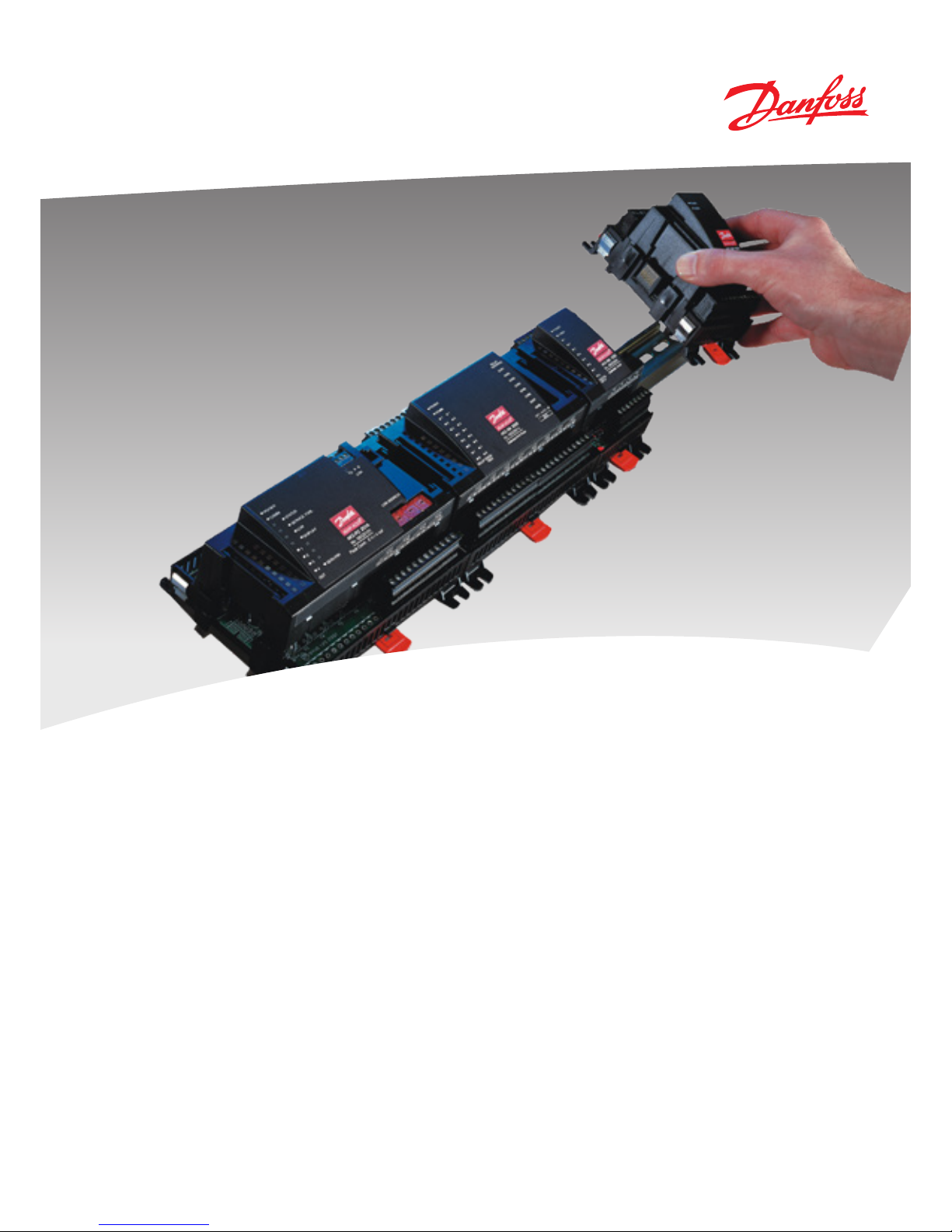
1. Introduction
Evaporator control of one, two, three or four evaporators
Control of cool or frost
room
Control of cool or frost
appliance
Page 4
4 RS8GM222 © Danfoss 10-2014 AK-CC 750 - 080Z0130 & 080Z0139
Principles
The great advantage of this series of controllers is that it can
be extended as the size of the plant is increased. It has been
developed for refrigeration control systems, but not for any
specic application – variation is created through the read-in
software and the way you choose to dene the connections.
It is the same modules that are used for each regulation and the
composition can be changed, as required. With these modules
(building blocks) it is possible to create a multitude of various
kinds of regulations. But it is you who must help adjusting the
regulation to the actual needs – these instructions will assist
you to nd your way through all the open questions so that the
regulation can be dened and the connections made.
Advantages
• The controller’s size can “grow” as systems grow
• The software can be set for one or more regulations
• Several regulations with the same components
• Extension-friendly when systems requirements are changed
• Flexible concept:
- Controller series with common construction
- One principle – many regulation uses
- Modules are selected for the actual connection requirements
- The same modules are used from regulation to regulation
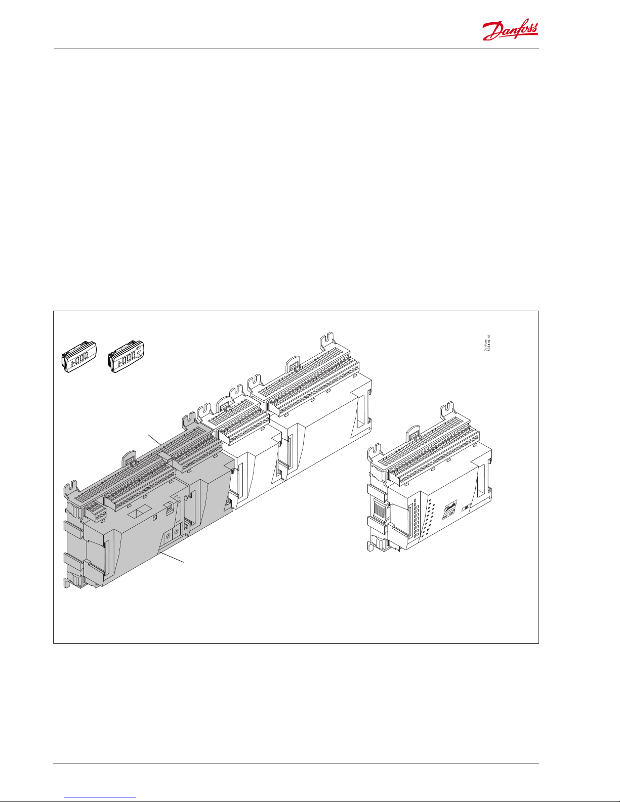
Controller
Top part
Extension modules
If the system grows and more functions have to be controlled, the regulation can be
extended.
With extra modules more signals can be received and more relays cut in and out –
how many of them – and which – is determined by the relevant application.
Bottom part
The controller is the cornerstone of the regulation. The module has inputs and
outputs capable of handling small systems.
• The bottom part – and hence the terminals – are the same for all controller types.
• The top part is the intelligence with software. This unit will vary according to controller type. But it will always be supplied together with the bottom part.
• In addition to the software the top part is provided with connection for data communication and address setting.
A regulation with few connections can
be performed with the controller module
alone
If there are many connections one or more extension modules have to be mounted
Examples
Page 5
AK-CC 750 - 080Z0130 & 080Z0139 RS8GM222 © Danfoss 10-2014 5
Direct connection
Setup and operation of an AK controller must be accomplished via
the “AK-Service Tool” software program.
The programme is installed on a PC, and setup and operation of
the various functions are carried out via the controller’s menu
displays.
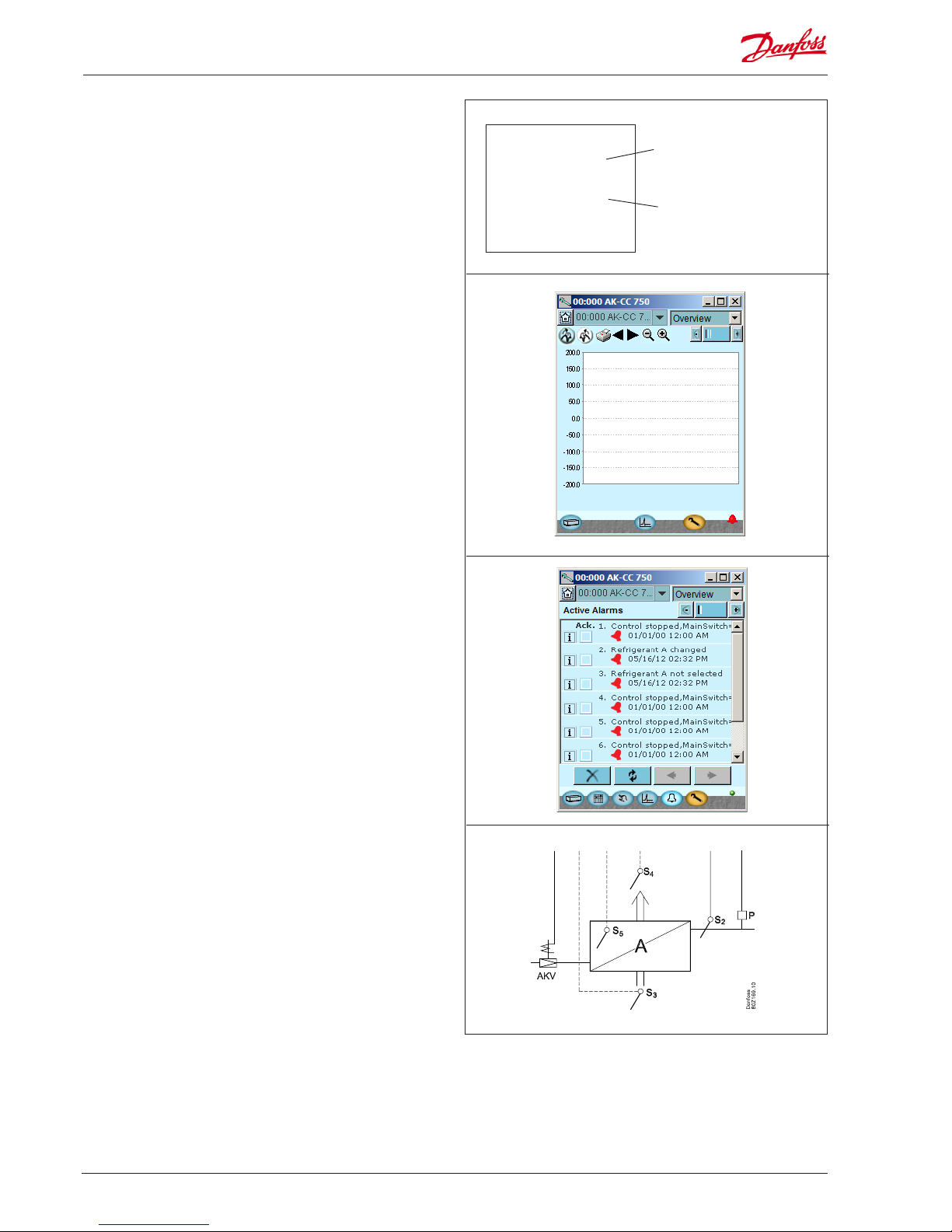
Displays
The menu displays are dynamic, so that dierent settings in one
menu will result in dierent setting possibilities in other menus.
A simple application with few connections will give a setup with
few settings.
A corresponding application with many connections will give a
setup with many settings.
From the overview display there is access to further displays for
the regulation.
At the bottom of the display there is access to a number of general
functions, such as “time table”, “manual operation”, “log function”,
“alarms”, and “service” (conguration).
Network linking
The controller can be linked up into a network together with other
controllers in an ADAP-KOOL® refrigeration control system.
AK-SC 255, 355 or SM850 can be used as a system unit.
After initial setup, operation can be performed from control
system.
080Z0130 is equiped with LON TP 78
080Z0139 is equiped with LON RS 485.
Users
The controller comes supplied with several languages, one of
which can be selected and employed by the user. If there are several users, they may each have their choice of language. All users
must be assigned a user prole which either gives access to full
operation or gradually limits the operation to the lowest level that
only allows you “to see”.
External display
An external display can be tted in order for P0 (Suction) and Pc
(Condensing) readings to be displayed.
In AK-CC 750 up to 4 displays can be mounted.
Page 6
6 RS8GM222 © Danfoss 10-2014 AK-CC 750 - 080Z0130 & 080Z0139
■ Power
■ Comm
■ DO1 ■ Status
■ DO2 ■ Service Tool
■ DO3 ■ LON
■ DO4 ■ Alarm
■ DO5
■ DO6
■ DO7
■ DO8 ■ Service Pin
Light-emitting diodes
A number of light-emitting diodes makes it possible to follow the
signals that are received and transmitted by the controller.
Log
From the log function you can dene the measurements you wish
to be shown.
The collected values can be printed, or you may export them to a
le. You can open the le in Excel or import in AKM.
(The Log function is only available via AK-ST 500.)
If you are in a service situation you can show measurements in a
trend function. The measurements are then made real-time and
displayed instantly.
Alarm
The display gives you an overview of all active alarms. If you wish
to conrm that you have seen the alarm you can cross it o in the
acknowledge eld.
If you want to know more about a current alarm you can click on it
and obtain an information display on the screen.
A corresponding display exists for all earlier alarms. Here you can
upload information if you need further details about the alarm
history.
Adaptive defrost
AK-CC 750 is equipped with an adaptive defrost function. By using
an AKV valve as mass ow sensor for the supply of refrigerant the
control can monitor ice formation on the evaporator.
Function can cancel planned defrosts which are not necessary,
and on its own initiative start a defrost if the evaporator is about
to be blocked by rime and ice.
Slow ash = OK
Quick ash = answer from gateway/
installed in network
Constantly ON = error
Constantly OFF = error
Flash = active alarm/not cancelled
Constant ON = Active alarm/cancelled
(In 084Z0139 the alarm LED is moved to
position 5.)
Page 7

AK-CC 750 - 080Z0130 & 080Z0139 RS8GM222 © Danfoss 10-2014 7
2. Design of a controller
This section describes how the controller is designed.
The controller in the system is based on a uniform connection
platform where any deviations from regulation to regulation is
determined by the used top part with a specic software and
by which input and output signals the relevant application will
require. If it is an application with few connections, the controller
module (top part with belonging bottom part) may be sucient.
If it is an application with many connections it will be necessary to
use the controller module plus one or more extension modules.
This section will give you a survey of possible connections plus
assistance in selecting the modules required by your actual application.
Page 8
8 RS8GM222 © Danfoss 10-2014 AK-CC 750 - 080Z0130 & 080Z0139
Module survey
• Controller module – capable of handling minor plant requirements.
• Extension modules. When the numbers of evaporators becomes
greater and additional inputs or outputs are required, modules
can be attached to the controller. A plug on the side of the module will transmit the supply voltage and data communication
between the modules.
• Top part
The upper part of the controller module contains the intelligence. This is the unit where the regulation is dened and where
data communication is connected to other controllers in a bigger network.
• Connection types
There are various types of inputs and outputs. One type may, for
example, receive signals from sensors and switches, another may
receive a voltage signal, and a third type may be outputs with
relays etc. The individual types are shown in the table below.
• Optional connection
When a regulation is planned (set up) it will generate a need for
a number of connections distributed on the mentioned types.
This connection must then be made on either the controller
module or an extension module. The only thing to be observed
is that the types must not be mixed (an analog input signal must
for instance not be connected to a digital input).
• Programming of connections
The controller must know where you connect the individual
input and output signals. This takes place in a later conguration
where each individual connection is dened based on the
following principle:
- to which module
- at which point (”terminals”)
- what is connected (e.g. pressure transmitter/type/
pressure range)
Top part
Controller with analog inputs and
relay outputs.
Bottom part
Extension module with additional analog inputs
Extension module with additional relay outputs and additional
analog inputs.
The module with additional relay outputs is
also available in a version where the top part
is provided with change-over switches so
that the relays can be overridden.
External display
for appliance
temperature etc.
Page 9
AK-CC 750 - 080Z0130 & 080Z0139 RS8GM222 © Danfoss 10-2014 9
Type Analog
inputs
On/O outputs On/o supply voltage
(DI signal)
Module with
switches
For sensors, pressure transmitters
etc.
Relay
(SPDT)
Solid state Low voltage
(max. 80 V )
High voltage
(max. 260 V )
For override of relay
outputs
Controller 11 4 4 - - -
Extension modules
AK-XM 101A 8
AK-XM 102A 8
AK-XM 102B 8
AK-XM 204A 8
AK-XM 204B 8 x
AK-XM 205A 8 8
AK-XM 205B 8 8 x
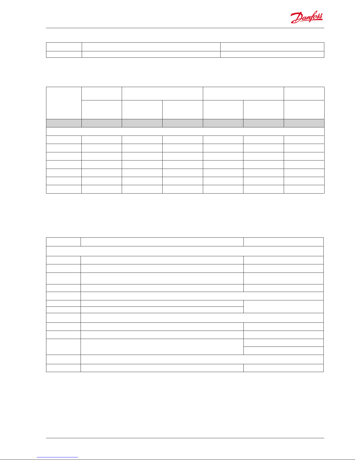
Type Function Application
Operation
AK-ST 500 Software for operation of AK controllers AK-operation
- Cable between PC and AK controller AK - Com port
-
Cable between zero modem cable and AK controller /
Cable between PDA cable and AK controller
AK - RS 232
- Cable between PC and AK controller AK - USB
Accessories Transformer module 230 V / 115 V to 24 V
AK-PS 075 18 VA, 24 V d.c.
Supply for controller
AK-PS 150 36 VA, 24 V d.c.
Accessories External display that can be connected to the controller module. For showing, say, the refrigeration appliances
EKA 163B Display
EKA 164B Display with operation buttons
- Cable between display and controller
Length = 6.5 ft
Length = 19.5 ft
Accessories Real time clock for use in controllers that require a clock function, but are not wired with data communication.
AK-OB 101A Real time clock with battery backup. To be mounted in an AK controller
Type Function Application
AK-CC 750 Controller for evaporator control Refrigeration appliances control
1. Controller
2. Extension modules and survey of inputs and outputs
3. AK operation and accessories
On the following pages there is data specic to each module.
Page 10
10 RS8GM222 © Danfoss 10-2014 AK-CC 750 - 080Z0130 & 080Z0139
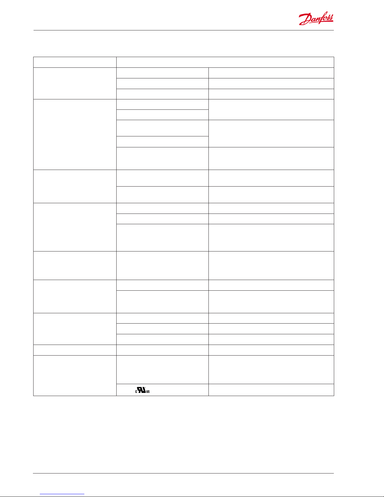
Common data for modules
Supply voltage 24 V d.c. / a.c. +/- 20%
Power consumption AK-__ (controller) 8 VA
AK-XM 101, 102, 103 2 VA
AK-XM 204, 205 5 VA
Analog inputs Pt 1000 ohm /0°C Resolution: 0.1°C
Accuracy: +/- 0.5°C (between -58°F and +122°F)
PTC 1000 ohm /0°C
Pressure transmitter type AKS 32R / AKS
2050 / AKS 32 (1-5 V)
Resolution:1 mV
Accuracy +/- 10 mV
Max. connection of 5 pressure transmitters on one module
Voltage signal 0-10 V
Contact function (On/O ) On at R < 20 ohm
O at R > 2K ohm
(Gold -plated contacts not necessary)
On/o supply voltage inputs Low voltage
0 / 80 V a.c./d.c.
O: U < 2 V
On: U > 10 V
High voltage
0 / 260 V a.c.
O: U < 24 V
On: U > 80 V
Relay outputs
SPDT
AC-1 (ohmic) 4 A
AC-15 (inductive) 3 A
U Min. 24 V
Max. 230 V
Low and high voltage must not be connected to the same
output group
Solid state outputs Can be used for loads that are cut in and
out frequently, e.g. :
rail heat, fans and AKV valve
Max. 240 V a.c. , Min. 48 V a.c.
Max. 0.5 A,
Leak < 1 mA
Max. 1 AKV
Ambient temperature During transport -40 to 158°F
During operation -4 to 131°F ,
0 to 95% RH (non condensing)
No shock inuences / vibrations
Enclosure Material PC / ABS
Density IP10 , VBG 4
Mounting For mounting on panel wall or DIN rail
Weight with screw terminals modules in100- / 200- / controller-series Ca. 7 oz / 17 oz / 21 oz
Approvals EU low voltage directive and EMC require-
ments are complied with
LVD tested according to EN 60730
EMC tested
Immunity according to EN 61000-6-2
Emission according to EN 61000-6-3
UL 873,
UL le number: E166834
The mentioned data applies to all modules.
If data is specic, this is mentioned together with the module in question.
Page 11
AK-CC 750 - 080Z0130 & 080Z0139 RS8GM222 © Danfoss 10-2014 11
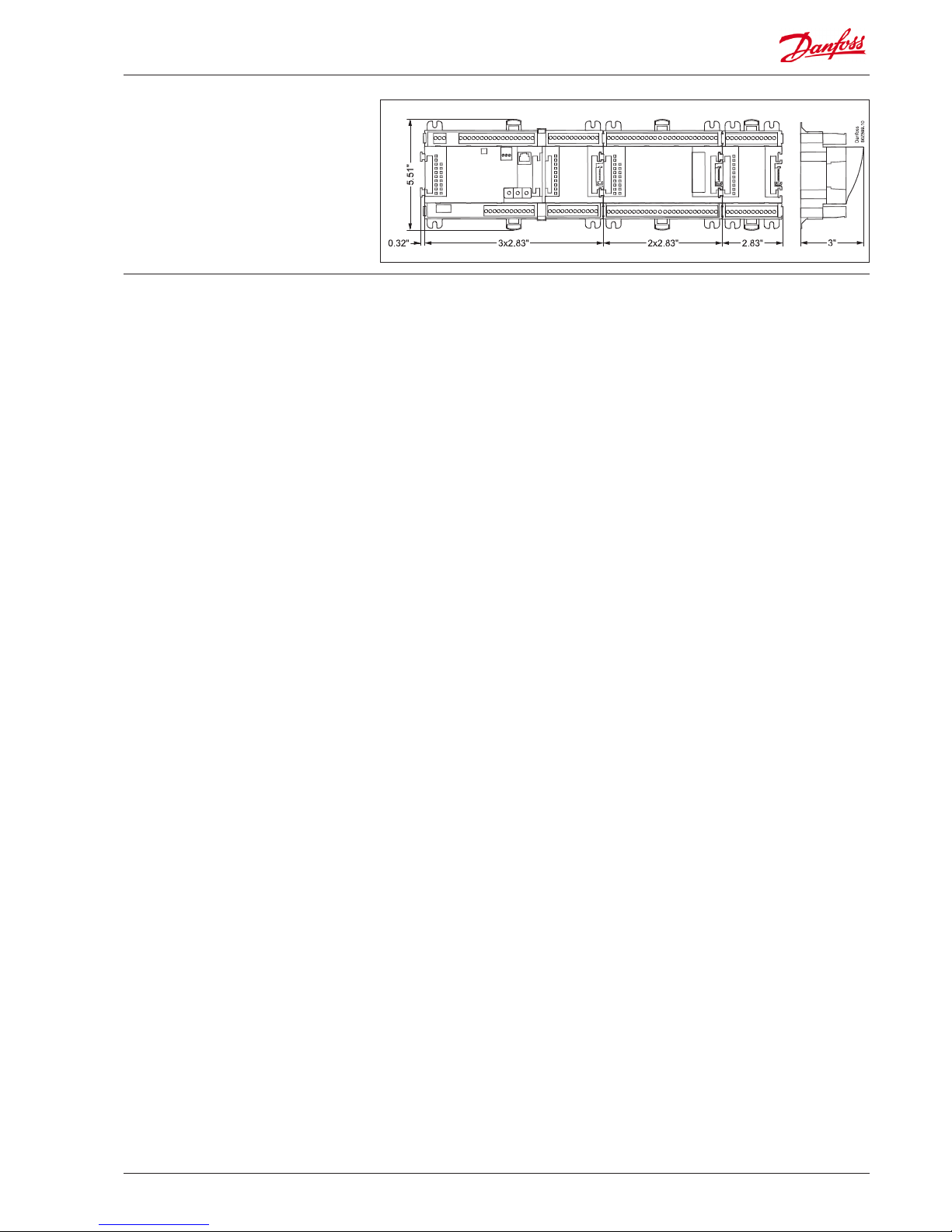
Dimensions
The module dimension is 72 mm (2.83 in).
Modules in the 100-series consist of one
module
Modules in the 200-series consist of two
modules
Controllers consist of three modules
The length of an aggregate unit =
n x 72 + 8 mm (n x 2.83 + 0.32 in).
Page 12
12 RS8GM222 © Danfoss 10-2014 AK-CC 750 - 080Z0130 & 080Z0139
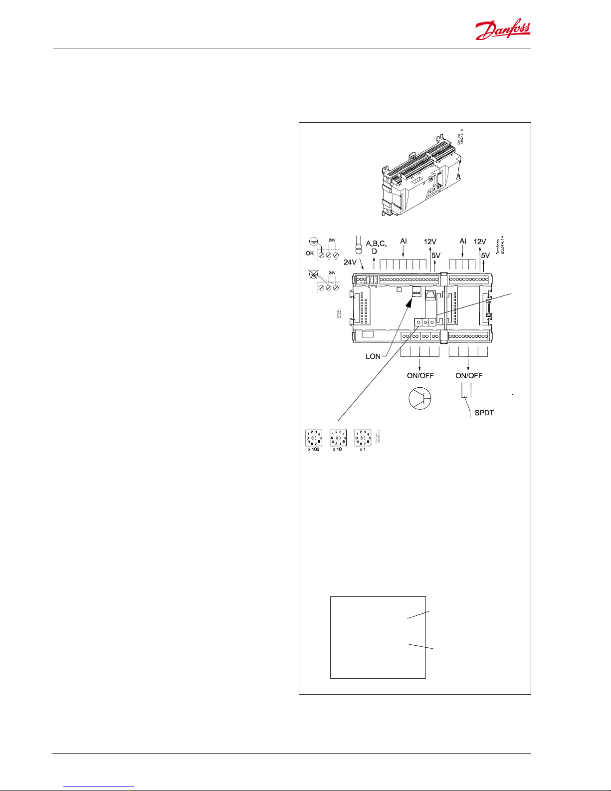
Controller
Function
There are several controllers in the series. The function is determined by the programmed software, but outwardly the controllers are identical – they all have the same connection possibilities:
11 analog inputs for sensors, pressure transmitters, voltage signals
and contact signals.
8 digital outputs, with 4 Solid state outputs and 4 relay outputs
Supply voltage
24 V a.c. or d.c. to be connected to the controller.
The 24 V must not be retransmitted and used by other controllers as it is not galvanically separated from inputs and outputs. In
other words, you must use a transformer for each controller. Class
II is required. The terminals must not be earthed.
The supply voltage to any extension modules is transmitted via
the plug on the right-hand side.
The size of the transformer is determined by the power requirement of the total number of modules.
The supply voltage to a pressure transmitter can be taken either
from the 5 V output or from the 12 V output depending on transmitter type.
Data communication
If the controller is to be included in a system, communication must take place via the LON connection.
The installation has to be made as mentioned in the separate instructions for LON communication.
Address setting
When the controller is connected to a system unit, the controller’s
address must be set between 1 and 200.
Scan function
When the controller is connected to the data communication
cable the system unit must have knowledge of the new controller.
This is obtained by the scan function in the system unit. The LED
“Status” will ash fast when the system unit sends an acceptance
message.
Operation
The conguration operation of the controller must take place from
the software programme “Service Tool”. The program must be
installed on a PC, and the PC must be connected to the controller
via the network plug on the front of the unit.
Light-emitting diodes
There are two rows with LED’s. They mean:
Left row:
• Voltage supply to the controller
• Communication active with the bottom PC board (red = error)
• Status of outputs DO1 to DO8
Right row:
• Software status (slow ash = OK)
• Communication with Service Tool
• Communication on LON
• Alarm when LED ashes
- 3 LED’s that are not used
• “Service Pin” switch has been activated
■ Power
■ Comm
■ DO1 ■ Status
■ DO2 ■ Service Tool
■ DO3 ■ LON
■ DO4 ■ Alarm
■ DO5
■ DO6
■ DO7
■ DO8 ■ Service Pin
PIN
Slow ash = OK
Quick ash = answer from gateway
Installation in network
Constantly ON = error
Constantly OFF = error
Flash = active alarm/not cancelled
Constant ON = Active alarm/cancelled
(In 084Z0139 the alarm LED is moved
to position 5.)
Address
Keep the safety
distance!
Low and high
voltage must not
be connected to
the same output
group
TP 78
or
RS 485
Page 13
AK-CC 750 - 080Z0130 & 080Z0139 RS8GM222 © Danfoss 10-2014 13
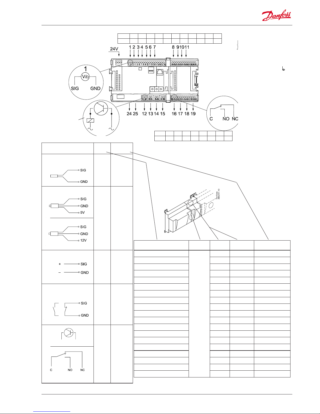
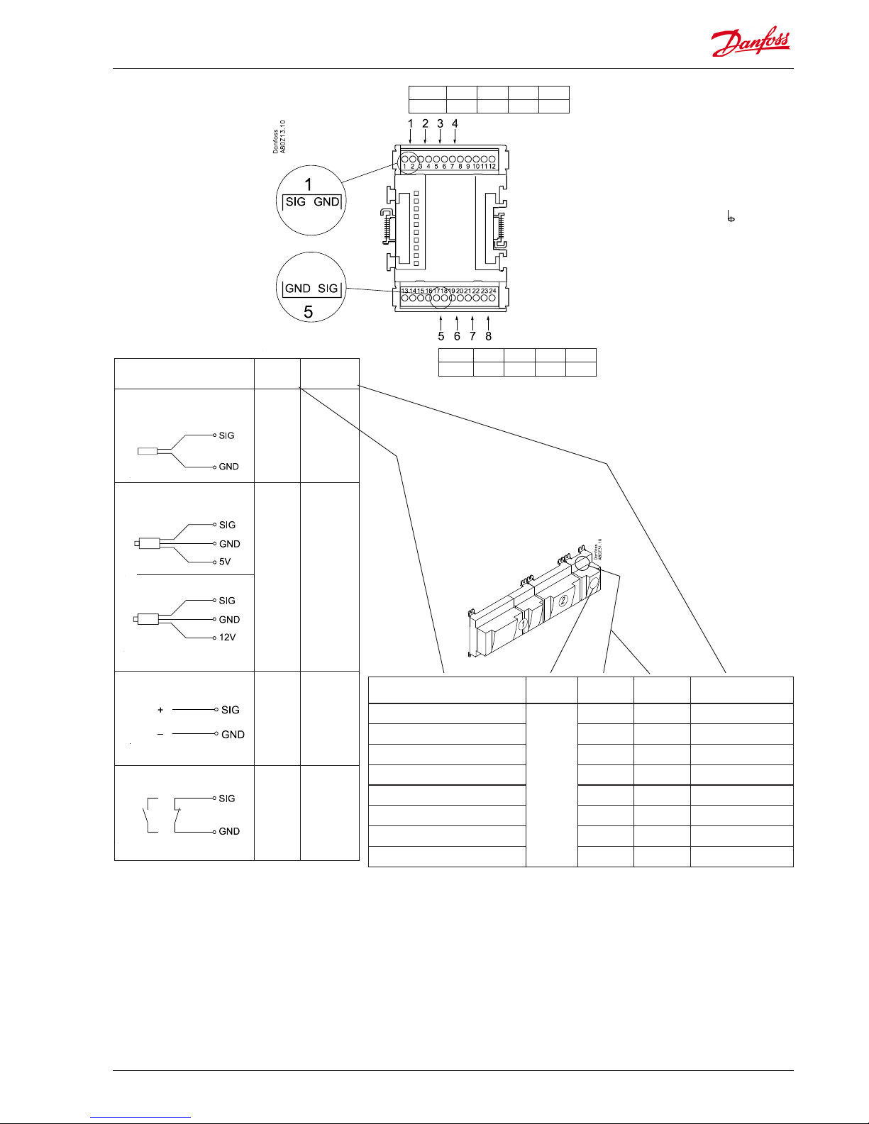
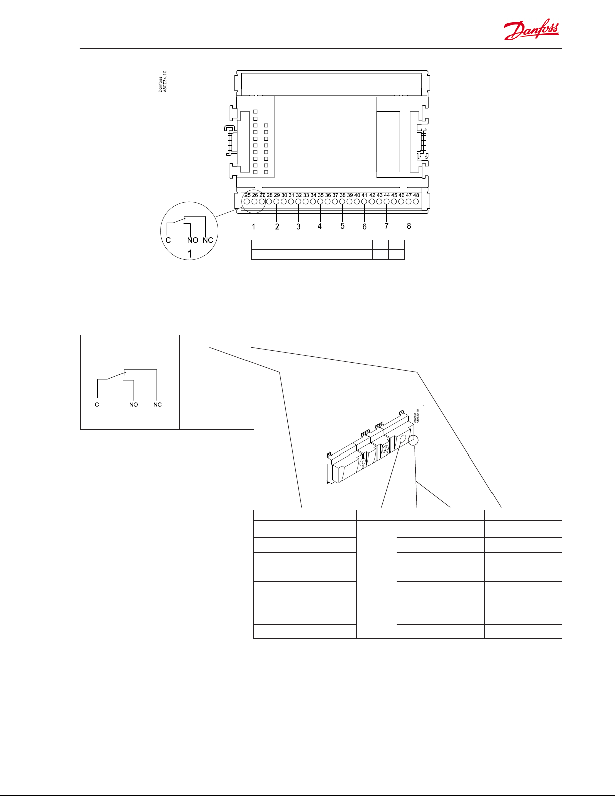
Point
Signal Signal
type
S
Pt 1000 ohm/0°C
S2,
S3
S4,
S5
Saux
Pt 1000
P
AKS 32R
AKS 2050
AKS 32
P0
Pc
Paux
AKS 32R
AKS 2050
-1 - xx bar
AKS 32
-1 - zz bar
U
...
0 - 5 V
0 - 10 V
On/O Ext.
Main
switch
Day/
Night
Door
Defrost
Active at:
Closed
/
Open
DO
AKV
Fan
Alarm
Light
Rail heat
Defrost
Night
blind
Valves
Compressor
Active at:
On
/
O
Signal Module Point
Terminal
Signal type /
Active at
1
1 (AI 1) 1 - 2
2 (AI 2) 3 - 4
3 (AI 3) 5 - 6
4 (AI 4) 7 - 8
5 (AI 5) 9 - 10
6 (AI 6) 11 - 12
7 (AI 7) 13 - 14
8 (AI 8) 19 - 20
9 (AI 9) 21 - 22
10 (AI 10) 23 - 24
11 (AI 11) 25 - 26
12 (DO 1) 31 - 32
13 (DO 2) 33 - 34
14 (DO 3) 35 - 36
15 (DO 4) 37 - 38
16 (DO 5) 39 - 40- 41
17 (DO6) 42 - 43 - 44
18 (DO7) 45 - 46 - 47
19 (DO8) 48 - 49 - 50
Terminal 15: 12 V
Terminal 16: 5 V
Terminal 27: 12 V
Terminal 28: 5 V
Terminal
17, 18, 29, 30:
(Cable screen)
Solid state outputs
on 12 - 15
Relay or AKV coil
fx 230 V a.c.
Relay outputs on
16 - 19
Analog
inputs
on 1 - 11
Point 1 2 3 4 5 6 7 8 9 10 11
Type AI1 AI2 AI3 AI4 AI5 AI6 AI7 AI8 AI9 AI10 AI11
Point 12 13 14 15 16 17 18 19
Type DO1 DO2 DO3 DO4 DO5 DO6 DO7 DO8
24 and 25 not
used at evaporator control
3: Brown
2: Blue
1: Black
3: Brown
2: Black
1: Red
AKV
20-23*)
*) 20 - 23: See Case
power module
Page 14
14 RS8GM222 © Danfoss 10-2014 AK-CC 750 - 080Z0130 & 080Z0139
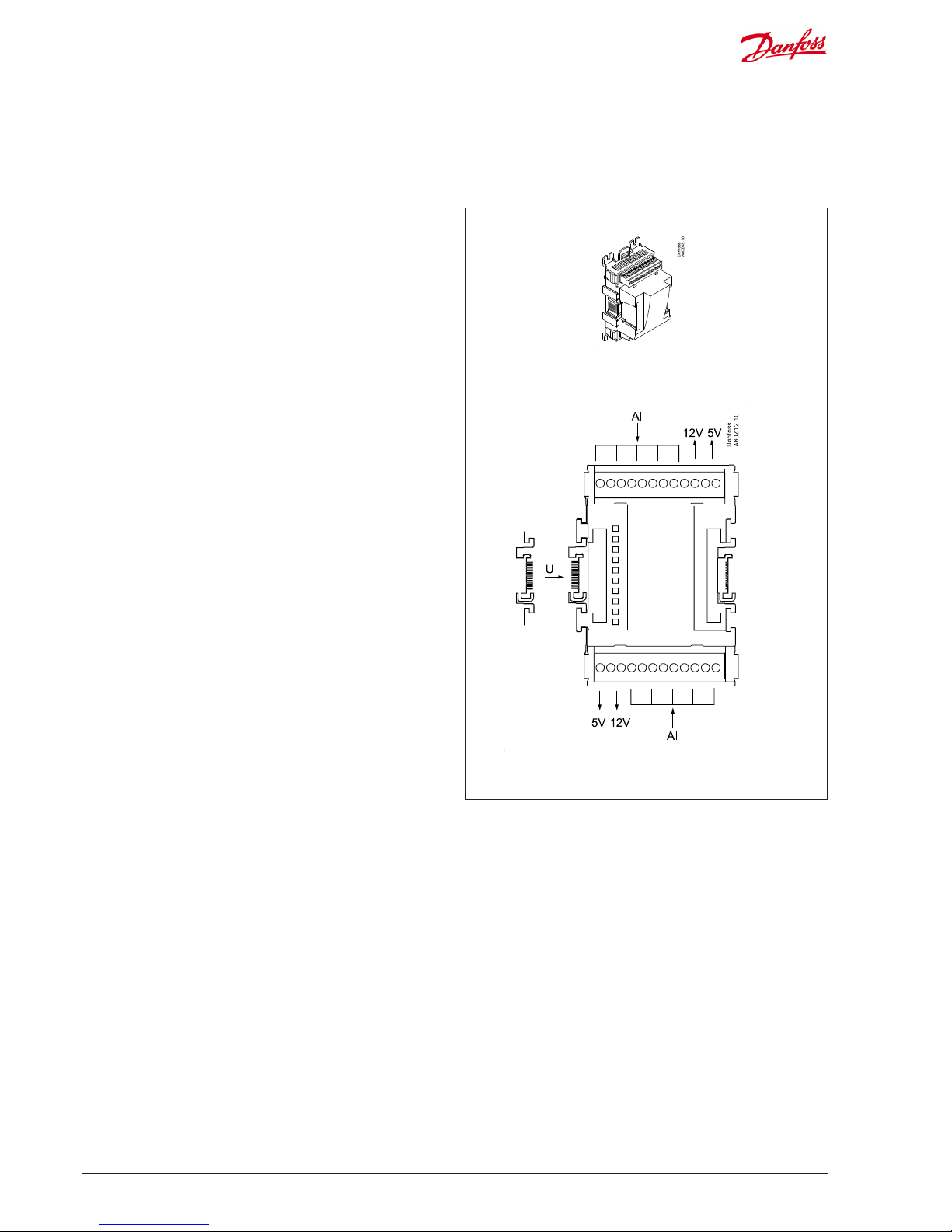
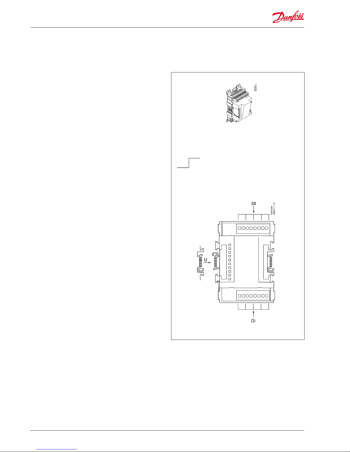
Extension module AK-XM 101A
Function
The module contains 8 analog inputs for sensors, pressure
transmitters, voltage signals and contact signals.
Supply voltage
The supply voltage to the module comes from the previous module in the row.
Supply voltage to a pressure transmitter can be taken from either
the 5 V output or the 12 V output depending on transmitter type.
Light-emitting diodes
Only the two top LED’s are used. They indicate the following:
• Voltage supply to the module
• Communication with the controller is active (red = error)
Page 15
AK-CC 750 - 080Z0130 & 080Z0139 RS8GM222 © Danfoss 10-2014 15
Signal Module Point
Terminal
Signal type /
Active at
1 (AI 1) 1 - 2
2 (AI 2) 3 - 4
3 (AI 3) 5 - 6
4 (AI 4) 7 - 8
5 (AI 5) 17 - 18
6 (AI 6) 19 - 20
7 (AI 7) 21 - 22
8 (AI 8) 23 - 24
Point
Signal Signal
type
S
Pt 1000 ohm/0°C
S2
S3
S4
S5
Saux
Pt 1000
P
AKS 32R
AKS 2050
AKS 32
P0
Pc
Paux
AKS 32R
AKS 2050
-1 - xx bar
AKS 32
-1 - zz bar
U
...
0 - 5 V
0 - 10 V
On/O
Ext.
Main
switch
Day/
Night
Door
Defrost
Active at:
Closed
/
Open
Point 5 6 7 8
Type AI5 AI6 AI7 AI8
Point 1 2 3 4
Type AI1 AI2 AI3 AI4
Terminal 9: 12 V
Terminal 10: 5 V
Terminal 15: 5 V
Terminal 16: 12 V
Terminal
11, 12, 13, 14:
(Cable screen)
At the top the
signal input is
the left of the
two terminals.
At the bottom
the signal input
is the right of the
two terminals.
3: Brown
2: Blue
1: Black
3: Brown
2: Black
1: Red
Page 16
16 RS8GM222 © Danfoss 10-2014 AK-CC 750 - 080Z0130 & 080Z0139
Extension module AK-XM 102A / AK-XM 102B
AK-XM 102B
Max. 230 V
On/O:
On: DI > 80 V a.c.
O: DI < 24 V a.c.
AK-XM 102A
Max. 24 V
On/O:
On: DI > 10 V a.c.
O: DI < 2 V a.c.
Function
The module contains 8 inputs for on/o voltage signals.
Signal
AK-XM 102A is for low voltage signals.
AK-XM 102B is for high voltage signals.
Supply voltage
The supply voltage to the module comes from the previous module in the row.
Light-emitting diodes
They indicate:
• Voltage supply to the module
• Communication with the controller is active (red = error)
• Status of the individual inputs 1 to 8 (when lit = voltage)
Page 17
AK-CC 750 - 080Z0130 & 080Z0139 RS8GM222 © Danfoss 10-2014 17
Signal Module Point Terminal Active at
1 (DI 1) 1 - 2
2 (DI 2) 3 - 4
3 (DI 3) 5 - 6
4 (DI 4) 7 - 8
5 (DI 5) 9 - 10
6 (DI 6) 11 - 12
7 (DI 7) 13 - 14
8 (DI 8) 15 - 16
Point
Signal Active at
DI
Ext.
Main
switch
Day/
Night
Door
Defrost
Closed
(voltage on)
/
Open
(voltage o)
Point 5 6 7 8
Type DI5 DI6 DI7 DI8
Point 1 2 3 4
Type DI1 DI2 DI3 DI4
AK-XM 102A: Max. 24 V
AK-XM 102B: Max. 230 V
Page 18
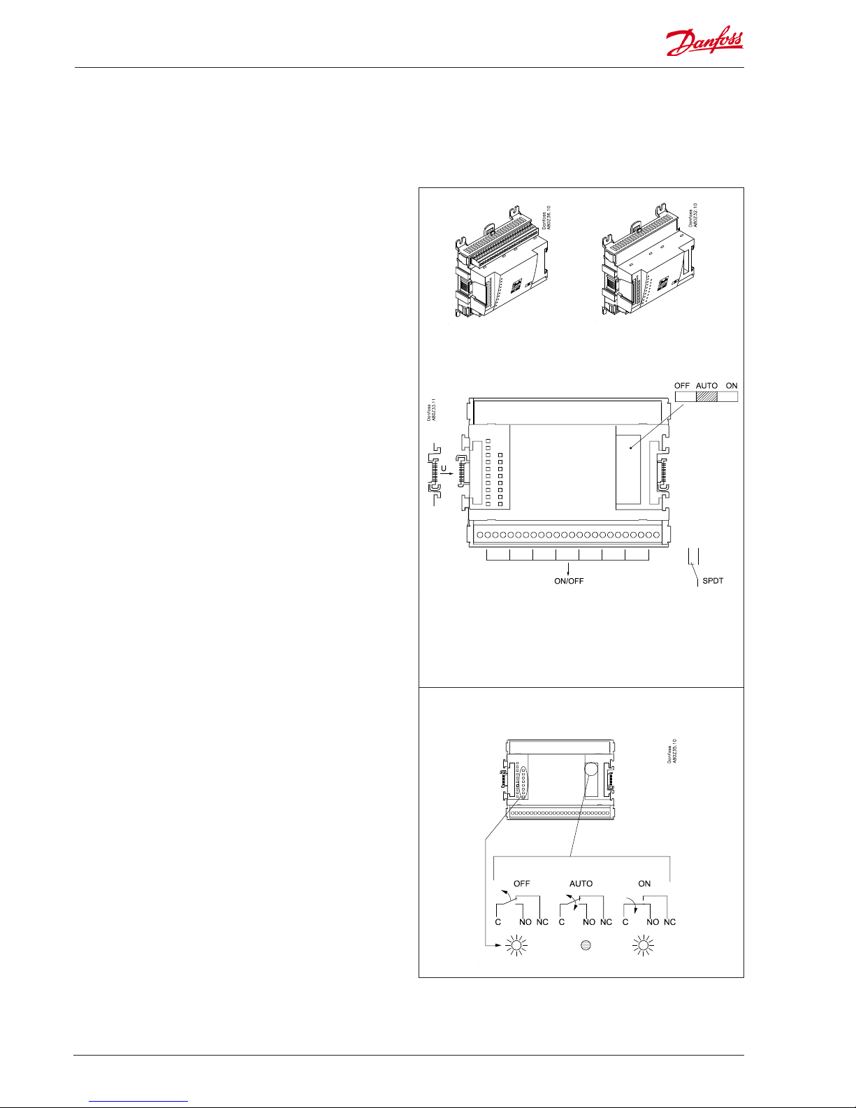
18 RS8GM222 © Danfoss 10-2014 AK-CC 750 - 080Z0130 & 080Z0139
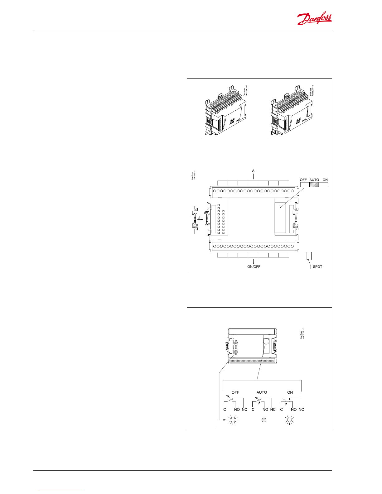
Extension module AK-XM 204A / AK-XM 204B
AK-XM 204A AK-XM 204B
Max. 230 V
AC-1: max. 4 A (ohmic)
AC-15: max. 3 A (Inductive)
Function
The module contains 8 relay outputs.
Supply voltage
The supply voltage to the module comes from the previous module in the row.
AK-XM 204B only
Override of relay
Eight change-over switches at the front make it possible to override the relay’s function.
Either to position OFF or ON.
In position Auto the controller carries out the control.
Light-emitting diodes
There are two rows with LED’s. They indicate the following:
Left row:
• Voltage supply to the controller
• Communication active with the bottom PC board (red = error)
• Status of outputs DO1 to DO8
Right row: (AK-XM 204B only):
• Override of relays
ON = override
OFF = no override
Fuses
Behind the upper part there is a fuse for each output.
Keep the safety distance!
Low and high voltage
must not be connected to
the same output group
AK-XM 204B
Override of relay
Page 19
AK-CC 750 - 080Z0130 & 080Z0139 RS8GM222 © Danfoss 10-2014 19
Point
Signal Module Point Terminal Active at
1 (DO 1) 25 - 27
2 (DO 2) 28 - 30
3 (DO 3) 31 - 33
4 (DO 4) 34 -36
5 (DO 5) 37 - 39
6 (DO 6) 40 - 41 - 42
7 (DO 7) 43 - 44 - 45
8 (DO 8) 46 - 47 - 48
Signal Active at
DO
Fan
Alarm
Light
Railheat
Defrost
Night
blind
Valve
Compressor
On
/
O
Point 1 2 3 4 5 6 7 8
Type DO1 DO2 DO3 DO4 DO5 DO6 DO7 DO8
Page 20
20 RS8GM222 © Danfoss 10-2014 AK-CC 750 - 080Z0130 & 080Z0139
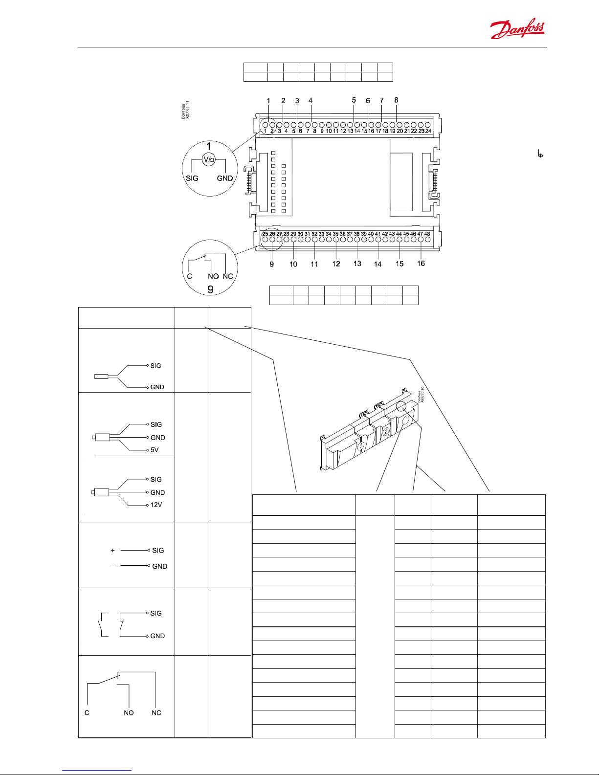
Extension module AK-XM 205A / AK-XM 205B
max. 10 V
AK-XM 205A AK-XM 205B
Max. 230 V
AC-1: max. 4 A (ohmic)
AC-15: max. 3 A (Inductive)
Function
The module contains:
8 analog inputs for sensors, pressure transmitters, voltage signals
and contact signals.
8 relay outputs.
Supply voltage
The supply voltage to the module comes from the previous module in the row.
AK-XM 205B only
Override of relay
Eight change-over switches at the front make it possible to override the relay’s function.
Either to position OFF or ON.
In position Auto the controller carries out the control.
Light-emitting diodes
There are two rows with LED’s. They mean:
Left row:
• Voltage supply to the controller
• Communication active with the bottom PC board (red = error)
• Status of outputs DO1 to DO8
Right row: (AK-XM 205B only):
• Override of relays
ON = override
OFF = no override
Fuses
Behind the upper part there is a fuse for each output.
Keep the safety distance!
Low and high voltage
must not be connected to
the same output group
AK-XM 205B
Override of relay
Page 21
AK-CC 750 - 080Z0130 & 080Z0139 RS8GM222 © Danfoss 10-2014 21
Point
Signal Module Point
Terminal
Signal type /
Active at
1 (AI 1) 1 - 2
2 (AI 2) 3 - 4
3 (AI 3) 5 - 6
4 (AI 4) 7 - 8
5 (AI 5) 13 - 14
6 (AI 6) 15 - 16
7 (AI 7) 17 - 18
8 (AI 8) 19 -20
9 (DO 1) 25 - 26 - 27
10 (DO 2) 28 - 29 - 30
11 (DO 3) 31 - 30 - 33
12 (DO 4) 34 - 35 - 36
13 (DO 5) 37 - 36 - 39
14 (DO6) 40 - 41 - 42
15 (DO7) 43 - 44 - 45
16 (DO8) 46 - 47 - 48
Signal Signal
type
S
Pt 1000 ohm/0°C
S2,
S3
S4,
S5
Saux
Pt 1000
P
AKS 32R
AKS 2050
AKS 32
P0
Pc
Paux
AKS 32R
AKS 2050
-1 - xx bar
AKS 32
-1 - zz bar
U
...
0 - 5 V
0 - 10 V
On/O
Ext. Main
switch
Day/
Night
Door
Defrost
Active at:
Closed
/
Open
DO
Fan
Alarm
Light
Antisweat
Defrost
Night
blind
Valve
Compr.
Active at:
on
/
O
Terminal 9: 12 V
Terminal 10: 5 V
Terminal 21: 12 V
Terminal 22: 5 V
Terminal 11, 12, 23, 24 :
(Cable screen)
Point 9 10 11 12 13 14 15 16
Type DO1 DO2 DO3 DO4 DO5 DO6 DO7 DO8
Point 1 2 3 4 5 6 7 8
Type AI1 AI2 AI3 AI4 AI5 AI6 AI7 AI8
3: Brown
2: Blue
1: Black
3: Brown
2: Black
1: Red
Page 22
22 RS8GM222 © Danfoss 10-2014 AK-CC 750 - 080Z0130 & 080Z0139
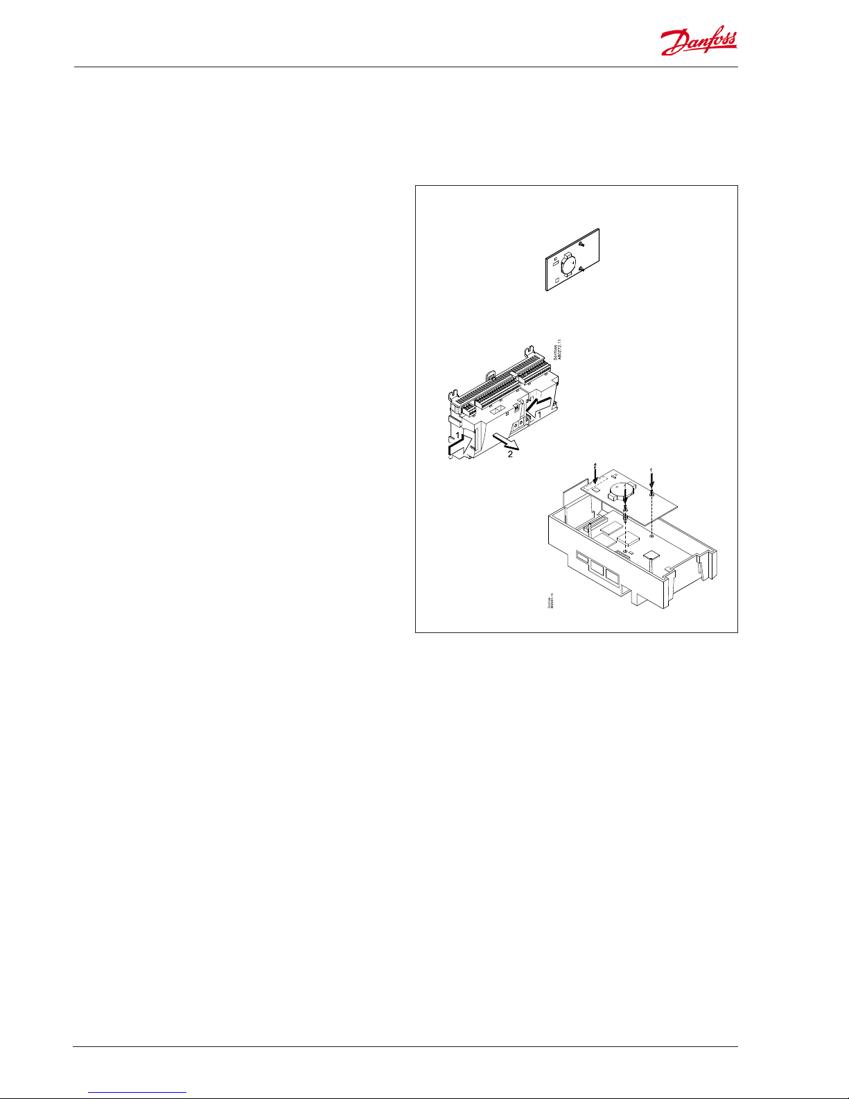
Extension module AK-OB 101A
Function
The module is a real time clock module with battery backup.
The module can be used in controllers that are not linked up in
a data communication unit together with other controllers. The
module is used here if the controller needs battery backup for the
following functions
• Clock function
• Fixed times for day/night change-over
• Fixed defrost times
• Saving of alarm log in case of power failure
• Saving of temperature log in case of power failure
Connection
The module is provided with plug connection.
Placing
The module is placed on the PC board inside the top part.
Point
No point for a clock module to be dened – just connect it.
Working life of the battery
The working life of the battery is several years – even if there are
frequent power failures.
An alarm is generated when the battery has to be replaced.
After the alarm there are still several months of operating hours
left in the battery.
Page 23
AK-CC 750 - 080Z0130 & 080Z0139 RS8GM222 © Danfoss 10-2014 23
EKA 163B EKA 164B
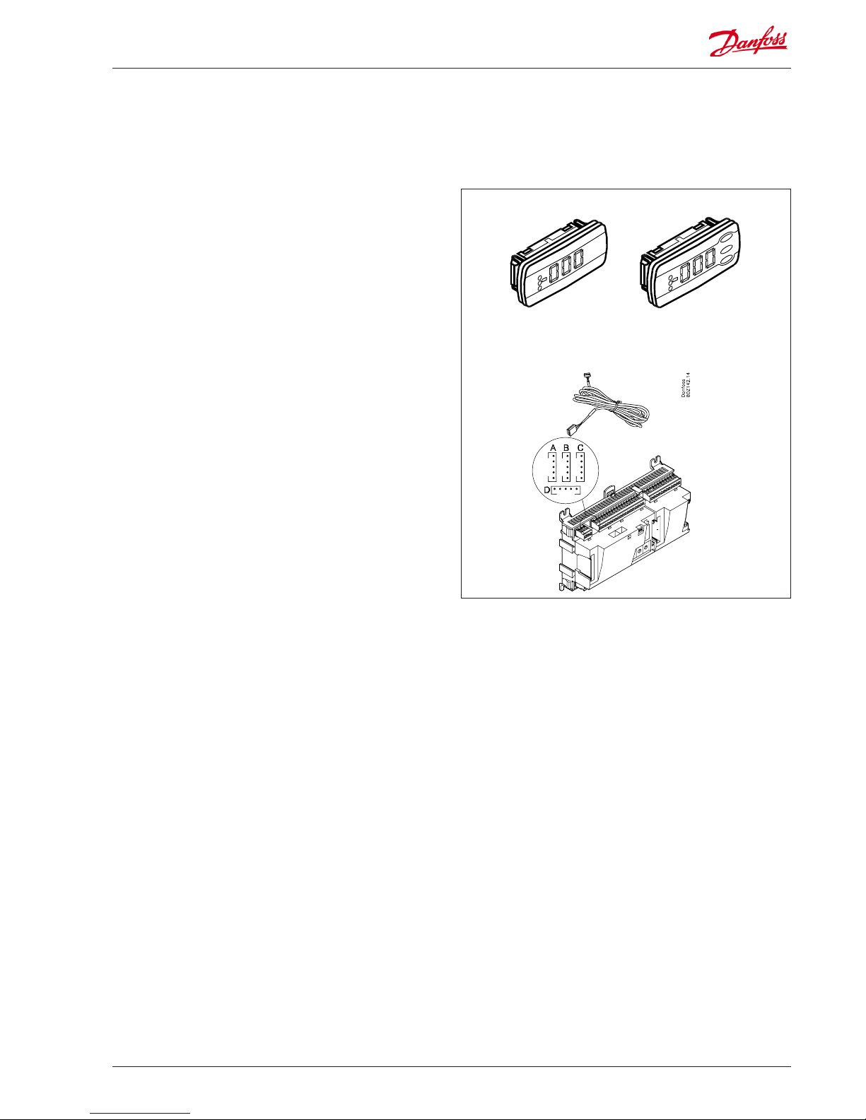
Display module EKA 163B / EKA 164B
Function
Display of important measurements from the controller, e.g.
appliance temperature.
Setting of the individual functions can be performed by using the
display with control buttons.
It is the controller used that determines the measurements and
settings that can occur.
Connection
The extension module is connected to the controller module via
a cable with plug connections. You have to use one cable per
module. The cable is supplied in various lengths.
Both types of display (with or without control buttons) can be
connected to either display output A, B, C and D.
When the controller starts up, the display will show the output
that is connected.
- - 1 = output A
- - 2 = output B
etc.
Placing
The extension module can be placed at a distance of up to 15 m
from the controller module.
Point
No point has to be dened for a display module – you simply
connect it.
Page 24
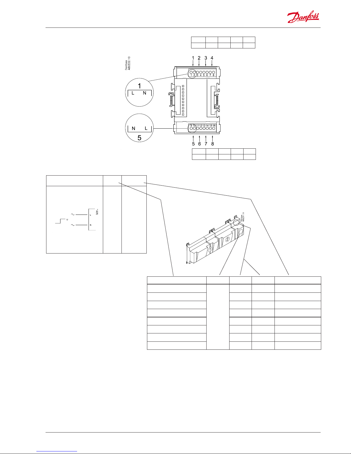
24 RS8GM222 © Danfoss 10-2014 AK-CC 750 - 080Z0130 & 080Z0139
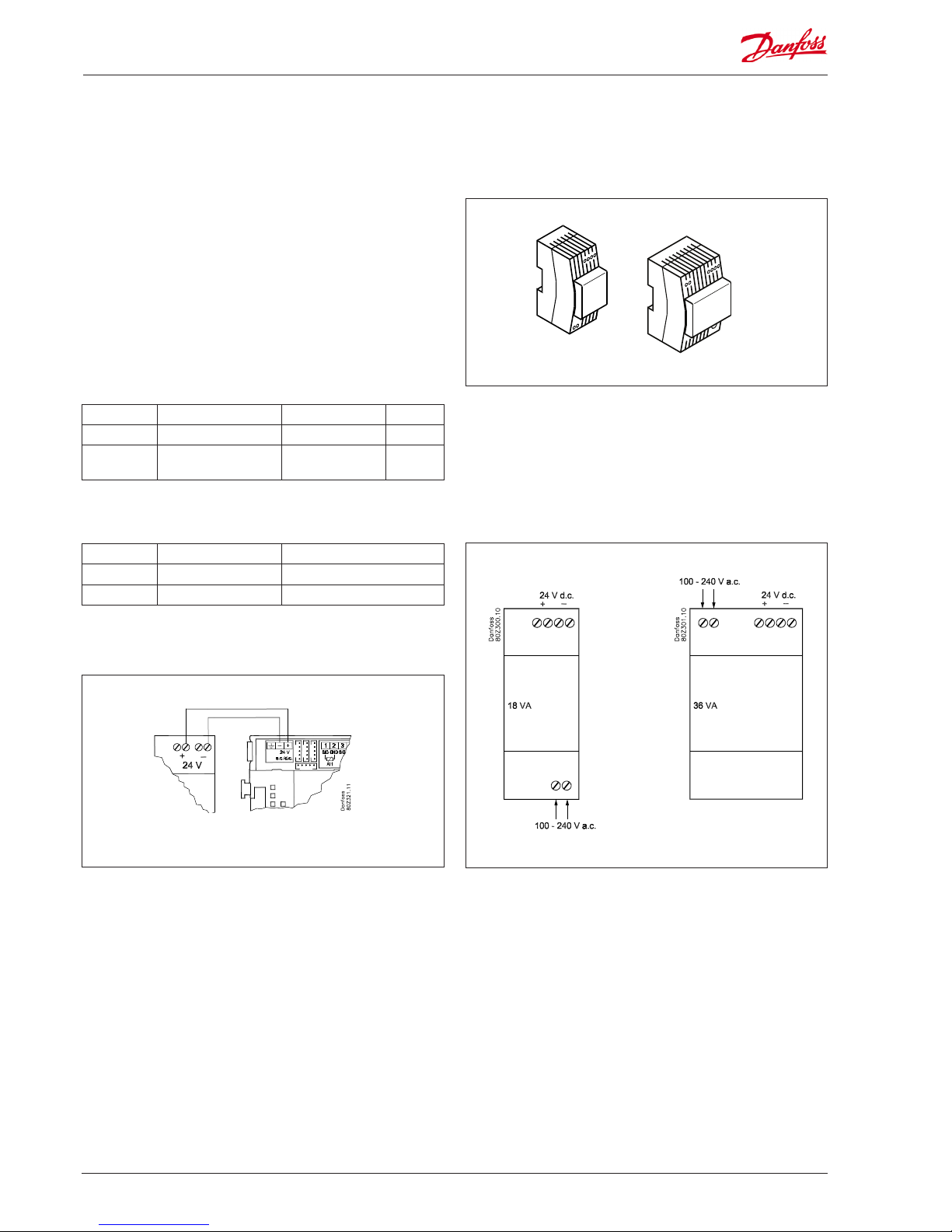
Transformer module AK-PS 075 / 150
AK-PS 075
AK-PS 150
Function
24 V supply for controller.
Supply voltage
230 V a.c or 115 V a.c. (from 100 V a.c. to 240 V a.c.)
Placing
On DIN-rail
Eect
Type Output tension Output current Power
AK-PS 075 24 V d.c. 0.75 A 18 VA
AK-PS 150 24 V d.c.
(adjustable)
1.5 A 36 VA
Dimension
Type High Width
AK-PS 075 90 mm 36 mm
AK-PS 150 90 mm 54 mm
Supply to a controller
Connections
Page 25
AK-CC 750 - 080Z0130 & 080Z0139 RS8GM222 © Danfoss 10-2014 25
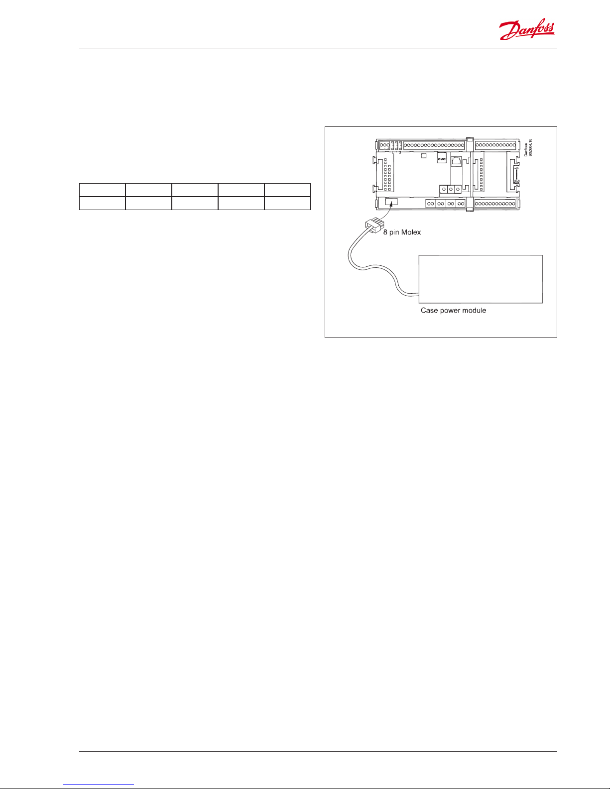
Case Power module
Point 20 21 22 23
Type ASH Light Def Fan
Relay output:
• Anti Sweat Heater
• Light
• Defrost
• Fan
If the AK-CC 750 must be connected to an existing Case Power
Module, it must be done as follows:
Connect the Case Power module via the 8-pin Molex connector.
AK-CC 750 are using the following points:
Page 26

26 RS8GM222 © Danfoss 10-2014 AK-CC 750 - 080Z0130 & 080Z0139
Functions
Clock function
Clock function and change-over between summer time and winter time are contained in the controller.
The clock is zeroset when there is power failure.
The clock’s setting is maintained if the controller is linked up in a
network with a gateway, a system manager or a clock module can
be mounted in the controller.
Start/stop of regulation
Regulation can be started and stopped via the software. External
start/stop can also be connected.
Alarm function
If the alarm is to be sent to a signal transmitter, a relay output will
have to be used.
Extra temperature sensors and pressure sensors
If additional measurements have to be carried out beyond the
regulation, sensors can be connected to the analog inputs.
Forced control
The software contains a forced control option. If an extension
module with relay outputs is used, the module’s top part can be
with change-over switches – switches that can override the individual relays into either OFF or ON position.
Data communication
The controller module has terminals for LON data communication.
The requirements to the installation are described in a separate
document. Literature number RC8AC.
Preface to design
Be aware of the following when the number of extension modules
is being planned. A signal may have to be changed, so that an additional module may be avoided.
• An ON/OFF signal can be received in two ways. Either as a
contact signal on an analog input or as voltage on a low or highvoltage module.
• An ON/OFF output signal can be given in two ways. Either with
a relay switch or with solid state. The primary dierence is the
permitted load and that the relay switch contains a cutout
switch.
Mentioned below is a number of functions and connections that
may have to be considered when a regulation has to be planned.
There are more functions in the controller than the ones mentioned here, but those mentioned have been included in order
that the need for connections can be established.
Page 27
AK-CC 750 - 080Z0130 & 080Z0139 RS8GM222 © Danfoss 10-2014 27
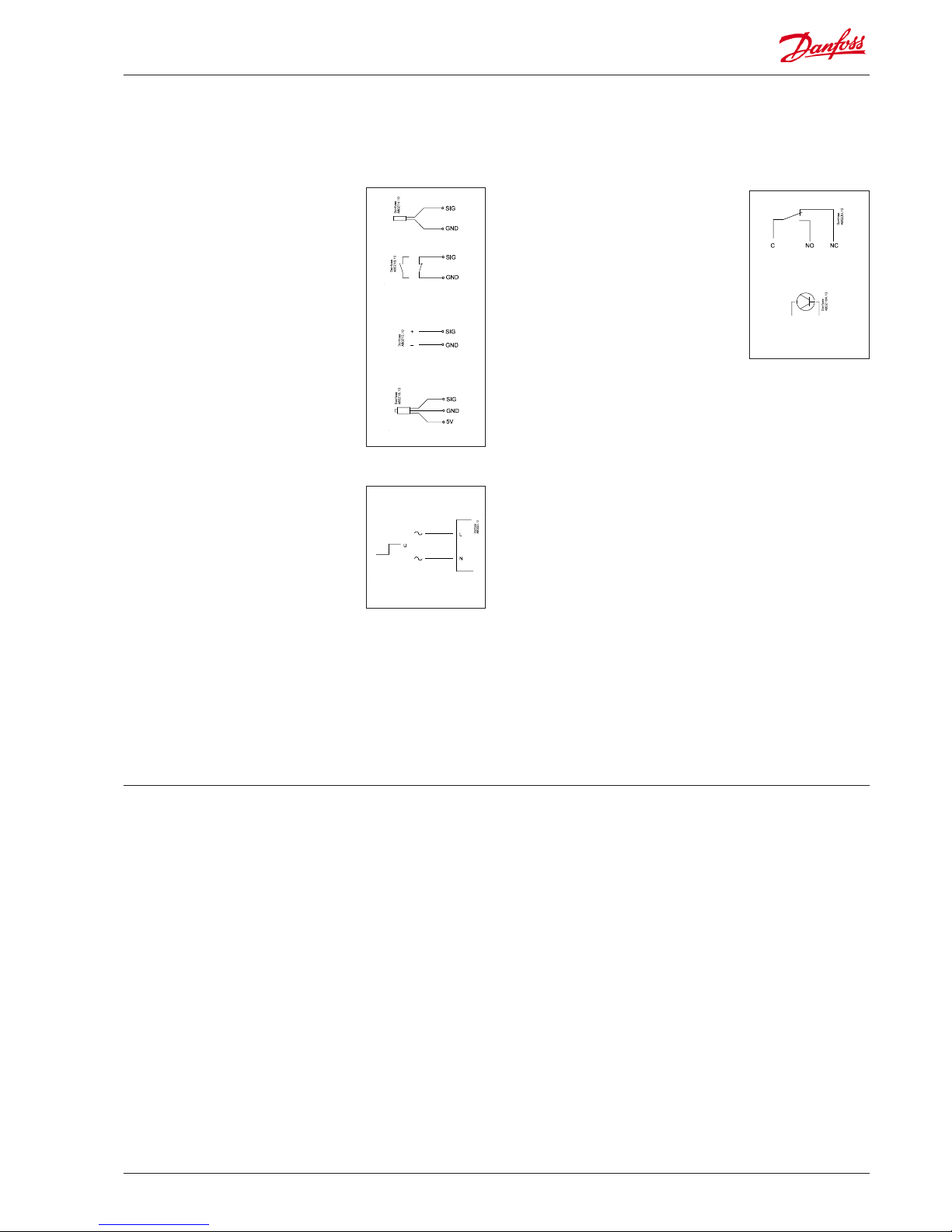
ON/OFF output signals ”DO”
There are two types, as follows:
• Relay outputs
All relay outputs are with change-over
relay so that the required function can be
obtained when the controller is without
voltage.
• Solid state outputs
Primarily for AKV valves which connect
quickly. But output can cut an external
relay in and out, as with a relay output.
The output is only found on the
controller module.
When programming the function must be set:
• Active when the output is activated
• Active when the output is not activated.
Connections
In principle there are the following types of connections:
Analog inputs ”AI”
This signal must be connected to two
terminals.
Signals can be received from the following
sources:
• Temperature signal from Pt 1000 ohm
temperature sensor
• Contact signal where the input is shortcircuited or ”opened”, respectively
• Voltage signal from 0 to 10 V
• Signal from pressure transmitter AKS 32,
AKS 32R or AKS 2050.
The supply voltage is supplied from the
module’s terminal board where there is
both a 5 V supply and a 12 V supply.
When programming the pressure transmitter’s pressure range must be set.
ON/OFF voltage inputs ”DI”
This signal must be connected to two
terminals.
• The signal must have two levels, either 0 V
or ”voltage” on the input.
There are two dierent extension
modules for this signal type:
- low-voltage signals, e.g. 24 V
- high-voltage signals, e.g. 115 V
When programming the function must be set:
• Active when the input is without voltage
• Active when voltage is applied to the
input.
Limitations
As the system is very exible regarding the number of connected
units you must check whether your selection complies with the
few limitations there are.
The complexity of the controller is determined by the software,
the size of the processor, and the size of the memory. It provides
the controller with a certain number of connections from which
data can be downloaded, and others where coupling with relays
can be performed.
The controller is not made for use on plate heat exchanger.
✔ The sum of connections cannot exceed 80.
✔ The number of extension modules must be limited so that the
total power will not exceed 32 VA (including controller).
✔ No more than 5 pressure transmitters may be connected to one
controller module.
✔ No more than 5 pressure transmitters may be connected to one
extension module.
Page 28
28 RS8GM222 © Danfoss 10-2014 AK-CC 750 - 080Z0130 & 080Z0139
Design of a evaporator control
Procedure:
1. Make a sketch of the system in question
2. Check that the controller’s functions cover the required
application
3. Consider the connections to be made
4. Use the planning table. / Note down the number of connections
./ add up
5. Are there enough connections on the controller module? – If
not, can they be obtained by changing an ON/OFF input signal
from voltage signal to contact signal, or will an extension
module be required?
6. Decide which extension modules are to be used
7. Check that the limitations are observed
8. Calculate the total length of modules
9. The modules are linked together
10. The connection sites are established
11. Draw a connection diagram or a key diagram
12. Size of supply voltage/transformer
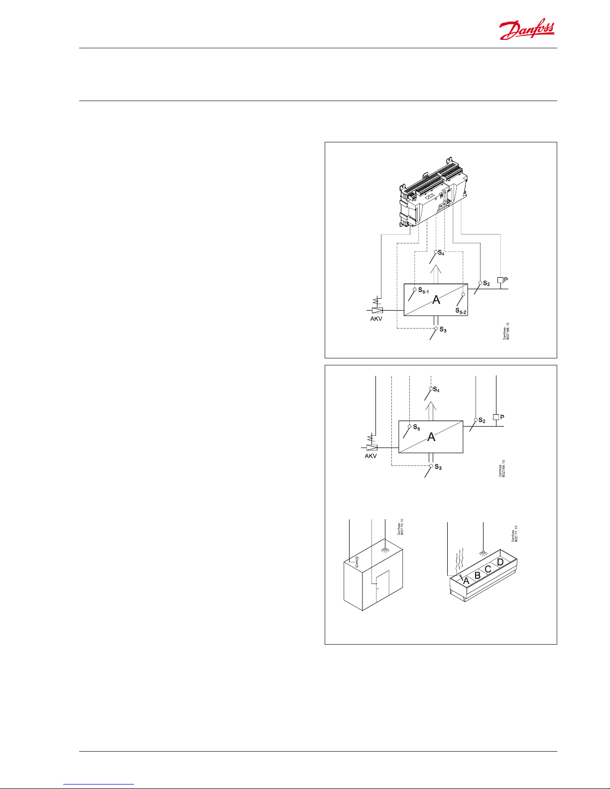
1
Sketch
2
Evaporator and refrigerator appliance
functions
Make a sketch of the system in question.
Follow these 12
steps
AK-CC
750
Application
Control of cold room or freezing room x
Control of refrigeration or freezing appliances x
Regulation of evaporators 1 - 4
Thermostat function
Common thermostat function for all sections x
Thermostat function for each section x
On/o thermostat with AKV or solenoid valve x
Modulating thermostat with AKV valve x
Change between two thermostat references (thermostat band) x
Day/night switch x
Displacement of reference via analog input signal x
Thermostat sensor before or after evaporator x
Thermostat sensor both before and after the evaporator (weighted
thermostat)
x
Alarm thermostat (weighted) x
Common functions
Fan control (pulsation) x
Rail heat control (pulsation) x
Compressor control. Relay active when refrigeration is demanded x
Appliance cleaning function x
Appliance shut down x
Door contact function x
Light function x
Night blind X
Forced closing x
Alarm output x
Start / stop of regulation x
Product sensor with alarm function 4
Page 29

AK-CC 750 - 080Z0130 & 080Z0139 RS8GM222 © Danfoss 10-2014 29
Day/night signal for raising the reference
The built-in week diagram can be used for raising the thermostat
reference, but it is also possible to use an external ON/OFF signal
or a signal via the network.
Product sensors
Each appliance section has a separate product sensor which can
be used for monitoring/registering the temperature.
Appliance cleaning function
A switch function with pulse pressure will activate the function
whereupon refrigeration will be stopped. The fans continue
operating.
”Later”: Next push on the switch will stop the fans.
”Still later”: Next push on the switch will restart refrigeration.
When a display is mounted at the appliance the various situations
may be followed by the readout:
Normal operation: Appliance temperature
1st push: Fan
2nd push: OFF
3rd push: Appliance temperature
Appliance shut down
Signal about shutdown can be received via data communication
or from a contact on a On/O input.
Door switch function
In freezing and coldrooms the door switch is used for switching
the light on and o, for starting and stopping the refrigeration,
and for sounding the alarm if the door has been open for a long
time
Light function
The light function can be activated by the door switch, the internal time diagram or a signal via the network.
Defrost sensor S5
On long evaporators it may be necessary to mount two sensors in
order to ensure the correct defrost of the evaporator. The sensors
are for example named S5A-1 and S5A-2.
“Inject ON” override function
The function closes expansion valves on the evaporator control
when all compressors are stopped.
The function can take place via the data communication, or it may
be wired via a relay output.
Adaptive defrost
The function requires signals from S3 and S4 as well as from
condensing pressure Pc. The expansion valve must furthermore
be type AKV.
The function cannot be used in combination with pulsation of
fans.
If you want to know more about the functions, go to
chapter 5.
A bit more about the functions
Common thermostat
The thermostat temperature can be either a weighting of the S3
and S4 sensors in section A.
Alternatively, the thermostat temperature can be a minimum
value, a maximum value or an average value of all S3 or S4 sensors
for the refrigeration sections used.
Modulating thermostat
AKV:
The function can only be used on central plant.
The opening degree of the valve is adjusted so that an accurate,
constant temperature is maintained. .
Solenoid valve:
This function can be used on both central systems and on indirect
refrigeration appliances. The valve's duty cycle is adapted so that
optimum temperature regulation is achieved on the basis of a
specic time period. The valve's duty cycle is desynchronised so
that an even load is achieved across the entire system
Changeover between two thermostat references
The function is used for appliances where contents are frequently
changed and where a dierent thermostat reference is required.
Changeover between the two references can take place by means
of a switch function.
Liquid injection
Control of AKV valves 4
Control of solenoid valves 4
Superheat regulation wit P0 and S2 measurement x
MOP control x
Refrigerant choice x
Defrost function
Electrical defrost 4
Warm Brine defrost, Hot gas defrost x
Smelt function x
Drip tray heat X
Adaptive defrost x
Defrost stop on temperature or time x
Coordinated defrost via network x
Miscellaneous
Alarm priorities x
Sensor correction x
Option for connection of separate display 4
System signals via data communication
Signal for P0-optimasation x
Night setback x
Inject ON-signal (forced closing) x
Light control x
Coordinated defrost x
Forced cooling x
Page 30

30 RS8GM222 © Danfoss 10-2014 AK-CC 750 - 080Z0130 & 080Z0139
Data from this example is used in the planning table on the
next page.
The result is that the following modules should be used:
• AK-CC 750 controller
• AK-XM 101A
• 3 pcs. EKA 163B
If the result had demonstrated that an additional output was
needed, AK-XM 205A or B would have been the required extension.
3
Connections
Here is a survey of the possible connections. The texts can be read
in context with the planning table in point 4.
Analog inputs
Temperature sensors each section
• S3 air sensor at evaporator inlet
• S4 air sensor at evaporator outlet (one of the S3/S4 sensors may
be omitted)
.• S5 defrost sensor. Two may be used for long sections
• Product sensor. Extra sensor that only checks the product tem-
perature
• S2 gas sensor at evaporator outlet (control of AKV valve).
Pressure transmitters
• P0 For registration of the evaporating pressure (control of AKV
valve).
• Pc For registration of the condensing pressure. Can be used in
connection with adaptive defrost, or the signal can be received
via data communication.
A pressure transmitter type AKS 32R can supply signals to ve
controllers
Voltage signal
Ext. Ref. is used if the thermostat reference is to be displaced
with a signal from another control.
On/O-inputs
Contact function (on an analog input) or voltage signal (on an
extension module)
• External start/stop of regulation
• Pulse pressure used for the ”appliance cleaning” function
• Switch for changeover between two temperature referenc
• Inject ON. Signal from a compressor control
• Pulse pressure for start of defrost
• Pulse pressure for opening/closing Night blind
• Door switch in coldroom
• External day/night signal (raises the temperature reference when
Night blind is used)
On/o-output
Relay outputs
• Defrost (one each section)
• Rail heat
• Fan motor
• Light
• Compressor (demand on cooling)
• Alarm relay
• Solenoid valve (EVR)
• Drain valve, Suction line valve
• Night blind
• Drip tray heat recovery
AKV Solid state outputs
The solid state outputs on the controller module are primarily
used for AKV valves, but may also be used for the functions mentioned under ”relay outputs”.
(The output will always be “OFF” when the controller is hit by
power failure).
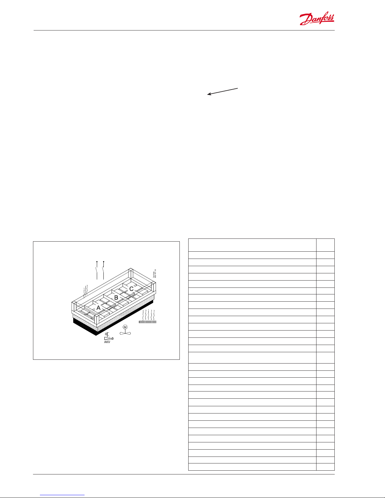
Example
• Freezing appliance with three sections
• AKV is used for injections (S2 and P0)
• Electric defrost with stop based on temperature (S5)
• Two thermostat sensors per section (S3 and S4)
• Control of fans and rail heat
• External start/stop (Main switch)
• Switch signal for appliance cleaning
• 3 display for monitoring of appliance temperature
Page 31

AK-CC 750 - 080Z0130 & 080Z0139 RS8GM222 © Danfoss 10-2014 31
4
6
5
The table helps you establish whether there are enough inputs and
outputs on the basic controller.
If there are not enough of them, the controllers must be extended by one or more of the mentioned extension modules.
Note down the connections you will require and add them up
Analog input signal
Example
On/o voltage signal
Example
On/o voltage signal
Example
On/O output signal
Example
Limitations
Analog inputs
Temperature sensors, S3, S4 6
Defrost sensors, S5 3
Product temperature sensor
Gas temperature sensor S2 3
Pressure transmitter P0 1
P = Max. 5 / module
Pressure transmitter Pc
Displacement of reference with analog signal
On/o inputs contact 24 V 230 V
External start/stop (Main switch) 1
Case cleaning (pulse pressure). Shutdown 1
Switch between two temperature references
Inject ON
Start of defrost (pulse pressure)
Door contact
Night setback
Open/ close Night blind (pulse pressure)
On/o outputs
AKV valves 3
Solenoid valves (when TEV valves is used))
Fans 1
Defrost (electric or hot gas valves) 3
Drain valve, suction line valve
Antisweat heat 1
Light
Night blind
Drip tray heat
Compressor
Alarm
Sum of connections for the regulation 15 8
Sum = max. 80
Number of connections on a controller module 11 11 0 0 0 0 8 8
Missing connections, if applicable 3 - - 0
The missing connections to be updated from one or more extension modules:
Sum of power
AK-XM 101A (8 analog inputs) +1
___ pcs. á 2 VA = __
AK-XM 102A (8 digital low voltage inputs)
___ pcs. á 2 VA = __
AK-XM 102B (8 digital high voltage outputs)
___ pcs. á 2 VA = __
AK-XM 204A / B (8 relay outputs)
___ pcs. á 5 VA = __
AK-XM 205A / B (8 analog inputs + 8 relay outputs)
___ pcs. á 5 VA = __
Case Power module (4 relay outputs. 12/24 A)
___ pcs. á 3 VA = __
1 pcs. á 8 VA = 8
Sum =
Sum = max. 32 VA
7
The example:
None of the 3 limitations are exceeded => OK
Planning table
Page 32

32 RS8GM222 © Danfoss 10-2014 AK-CC 750 - 080Z0130 & 080Z0139
Linking of modules
Start with the controller module and then mount the selected
extension modules. The sequence is of no importance.
However, you must not change the sequence, i.e. rearrange the
modules, after you have made the setup where the controller
is told which connections are found on which modules and on
which terminals.
The modules are attached to one another and kept together by a
connection which at the same time transmits the supply voltage
and the internal data communication to the next module.
Mounting and removal must always be performed when there is
no voltage.
The protective cap mounted on the controller’s plug connection
must be moved to the last vacant plug connection so that the
plug will be protected against short-circuit and dirt.
When the regulation has started the controller will all the time
check whether there is connection to the connected modules. This
status can be followed by the light-emitting diode.
When the two catches for the DIN rail mounting are in open position the module can be pushed into place on the DIN rail – no
matter where in the row the module is found.
Removal is likewise carried out with the two catches in the open
position.
8
9
Length
If you use many extension modules the controller’s length will
grow accordingly. The row of modules is a complete unit which
cannot be broken.
The module dimension is 72 mm (2.83").
Modules in the 100-series consist of one module
Modules in the 200-series consist of two modules
The controller consist of three modules
The length of an aggregate unit = n x 2.83" + 0.32"
or in an other way:
Module Type Number at Length
Controller module 1 x 8.82" = 8.82"
Extension module 200-series _ x 5.67" = ___ "
Extension module 100-series _ x 2.83" = ___ "
Total length = ___ "
Example continued:
Controller module + 1 extension module in 100-series =
8.82 + 2.83 = 11.65".
Page 33

AK-CC 750 - 080Z0130 & 080Z0139 RS8GM222 © Danfoss 10-2014 33
Determine the connection points
All connections must be programmed with module and point, so
in principle it does not matter where the connections are made, as
long as it takes place on a correct type of input or output.
• The controller is the rst module, the next one is 2, etc.
• A point is the two or three terminals belonging to an input or
output (e.g. two terminals for a sensor and three terminals for a
relay).
The preparation of the connection diagram and the subsequent
programming (conguration) should take place at the present
time. It is most easily accomplished by lling in the connection
survey for the relevant modules.
Principle:
Name On module On Point Function
fx Compressor 1 x x ON
fx Compressor 2 x x ON
fx Alarm relay x x OFF
fx Main switch x x Close
fx P0 x x AKS 32R 1-6 bar
The connection survey from the controller and any extension
modules are uploaded from the paragraph "Module survey. E.g.
controller module:
Module Point
10
Mind the numbering.
The right-hand part of the
controller module may look like
a separate module. But it isn’t.
- Columns 1, 2, 3 and 5 are used for the programming.
- Columns 2 and 4 are used for the connection diagram.
Example continued:
Signal Module Point Terminal
Signal type /
Active at
Air temperature - S3A
1
1 (AI 1) 1 - 2
Pt 1000
Air temperature- S3B
2 (AI 2) 3 - 4
Pt 1000
Air temperature- S3C
3 (AI 3) 5 - 6
Pt 1000
Air temperature - S4A
4 (AI 4) 7 - 8
Pt 1000
Air temperature - S4B
5 (AI 5) 9 - 10
Pt 1000
Air temperature - S4C
6 (AI 6) 11 - 12
Pt 1000
Defrost sensor - S5A
7 (AI 7) 13 - 14
Pt 1000
Defrost sensor - S5B
8 (AI 8) 19 - 20
Pt 1000
Defrost sensor - S5C
9 (AI 9) 21 - 22
Pt 1000
Gas temperature - S2A
10 (AI 10) 23 - 24
Pt 1000
Evaporator pressure - P0
11 (AI 11) 25 - 26
AKS32R-12
AKV A
12 (DO 1) 31 - 32
-
AKV B
13 (DO 2) 33 - 34
-
AKV C
14 (DO 3) 35 - 36
-
Fans
15 (DO 4) 37 - 38
ON
Defrost A
16 (DO 5) 39-40-41
ON
Defrost B
17 (DO6) 42-43-44
ON
Defrost C
18 (DO7) 45-46-47
ON
Rail heat
19 (DO8) 48-49-50
ON
24 -
25 -
Signal Module Point Terminal
Signal type /
Active at
Gas temperature - S2B
2
1 (AI 1) 1 - 2
Pt 1000
Gas temperature - S2C
2 (AI 2) 3 - 4
Pt 1000
External Start/stop
3 (AI 3) 5 - 6
Closed
Case cleaning (pulse pressure)
4 (AI 4) 7 - 8
Closed
5 (AI 5) 17 - 18
6 (AI 6) 19 - 20
7 (AI 7) 21 - 22
8 (AI 8) 23 - 24
Tip
The Appendix shows 80 general installation types.
If your plant closely resembles one of those shown, you
can use the connection points indicated for it.
Signal Module Point Terminal
Signal type /
Active at
1 (AI 1) 1 - 2
2 (AI 2) 3 - 4
3 (AI 3) 5 - 6
4 (AI 4) 7 - 8
Page 34

34 RS8GM222 © Danfoss 10-2014 AK-CC 750 - 080Z0130 & 080Z0139
11
Connection diagram
Drawings of the individual modules may be
ordered from Danfoss.
Format = dwg and dxf.
You may then yourself write the module
number in the circle and draw the individual
connections.
Example continued:
AKV A
S3A
3 x EKA 163B
S3B
1
1
1
2
2
3
3
4
4
567 8
121314
15
16
17
18
19
S3C
S4A
S5A
S5B
S2B
S4B
S4C
AKV B
AKV C
Fans
Def. A
Def.. B
Def.. C
Rail heat
9
S5C
S2C
10
S2A
Start/stop
11
P0
Case cleaning
2
Page 35

AK-CC 750 - 080Z0130 & 080Z0139 RS8GM222 © Danfoss 10-2014 35
Supply voltage
Supply voltage is only connected to the controller module. The
supply to the other modules is transmitted via the plug between
the modules. The supply must be 24 V +/-20%. One transformer
must be used for each controller. The transformer must be a class
II. The 24 V must not be shared by other controllers or units. The
analog inputs and outputs are not galvanically separated from the
supply.
The + and – 24V input must not be earthed.
Transformer size
The power consumption grows with the number of modules used:
Module Type Number á Eect
Controller 1 x 8 = 8 VA
Extension module 200-series _ x 5 = __ VA
Extension module 100-series _ x 2 = __ VA
Total ___ VA
12
Example continued:
Controller module 8 VA
+ 1 extension module in 100-series 2 VA
------
Transformer size (least) 10 VA
Page 36

36 RS8GM222 © Danfoss 10-2014 AK-CC 750 - 080Z0130 & 080Z0139
Type Analog
inputs
On/O outputs On/o supply voltage
(DI signal)
Module with
switches
Code no.
Example
continued
For sensors,
pressure transmitters etc.
Relay
(SPDT)
Solid state Low voltage
(max. 80 V )
High voltage
(max. 260 V )
For override
of relay
outputs
With screw
terminals
Controller 11 4 4 - - - -
Extension modules
AK-XM 101A 8 080Z0007 x
AK-XM 102A 8 080Z0008
AK-XM 102B 8 080Z0013
AK-XM 204A 8 080Z0011
AK-XM 204B 8 x 080Z0018
AK-XM 205A 8 8 080Z0010
AK-XM 205B 8 8 x 080Z0017
Type Function Application Code no.
Example
continued
Operation
AK-ST 500 Software for operation of AK controllers AK-operation 080Z0161 x
- Cable between PC and AK controller AK - Com port 080Z0262 x
-
Cable between zero modem cable and AK controller /
Cable between PDA cable and AK controller
AK - RS 232 080Z0261
Cable between PC and AK controller AK - USB 080Z0264
Accessories Transformer module 230 V / 115 V to 24 V
AK-PS 075 18 VA
Supply for controller
080Z0053 x
AK-PS 150 36 VA 080Z0054
Accessories External display that can be connected to the controller module. For showing, say, the appliance temperature
EKA 163B Display 084B8574 xxx
EKA 164B Display with operation buttons 084B8575
- Cable between display and controller
Length = 6.5 ft 084B7298 xxx
Length = 19.5 ft 084B7299
Accessories Real time clock for use in controllers that require a clock function, but are not wired with data communication.
AK-OB 101A Real time clock with battery backup. To be mounted in an AK controller 080Z0252
Type Function Application Language Code no.
Example
continued
AK-CC 750
Controller for evaporator control
With LON TP 78 communication
1, 2, 3 or 4 sections English (US), English (UK)
080Z0130 x
Controller for evaporator control
With LON RS 485 communication
080Z0139
1. Controller
2. Extension modules and survey for inputs and outputs
3. AK operation and accessories
Ordering
Page 37

AK-CC 750 - 080Z0130 & 080Z0139 RS8GM222 © Danfoss 10-2014 37
3. Mounting and wiring
This section describes how the controller:
• Is tted
• Is connected
We have decided to work on the basis of the example we went
through previously, i.e. the following modules:
• AK-CC 750 controller module (TP 78 version)
• AK-XM 101A analog output module
• 3 pcs. EKA 163B display
Page 38

38 RS8GM222 © Danfoss 10-2014 AK-CC 750 - 080Z0130 & 080Z0139
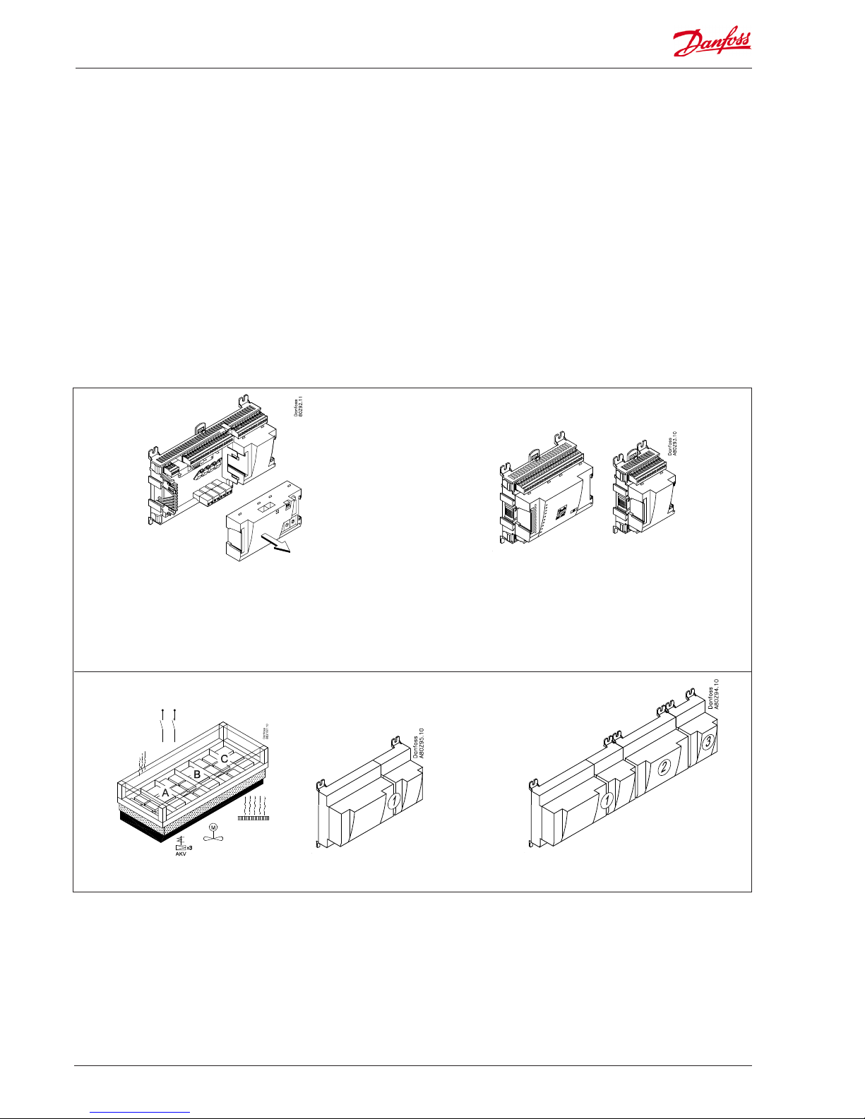
Mounting
Mounting of extension module on the
basic module
1. Move the protective cap
Remove the protective cap from the connection plug on the
right-hand side of the basic module.
Place the cap on the connection plug to the right of the extension module that is to be mounted on the extreme right-hand
side of the AK assembly.
2. Assemble the extension module and the basic
module
The basic module must not be connected to voltage.
In our example one extension module is to be tted to the basic
module. The sequence is thus:
All the subsequent settings that aect the two extension modules are
determined by this sequence.
When the two snap catches for the DIN rail mounting are in the open
position, the module can be pushed into place on the DIN rail – regardless of where the module is on the row.
Disassembly is thus done with the two snap catches in the open position.
Page 39

AK-CC 750 - 080Z0130 & 080Z0139 RS8GM222 © Danfoss 10-2014 39
Mounting and wiring - continued
Wiring
Decide during planning which function is to be connected and
where this will be.
1. Connect inputs and outputs
Here are the tables for the example:
The function of the switch functions can be seen in the last column.
Signal Module Point Terminal
Signal type /
Active at
Air temperature - S3A
1
1 (AI 1) 1 - 2
Pt 1000
Air temperature- S3B
2 (AI 2) 3 - 4
Pt 1000
Air temperature- S3C
3 (AI 3) 5 - 6
Pt 1000
Air temperature - S4A
4 (AI 4) 7 - 8
Pt 1000
Air temperature - S4B
5 (AI 5) 9 - 10
Pt 1000
Air temperature - S4C
6 (AI 6) 11 - 12
Pt 1000
Defrost sensor - S5A
7 (AI 7) 13 - 14
Pt 1000
Defrost sensor - S5B
8 (AI 8) 19 - 20
Pt 1000
Defrost sensor - S5C
9 (AI 9) 21 - 22
Pt 1000
Gas temperature - S2A
10 (AI 10) 23 - 24
Pt 1000
Evaporator pressure - P0
11 (AI 11) 25 - 26
AKS32R-12
AKV A
12 (DO 1) 31 - 32
-
AKV B
13 (DO 2) 33 - 34
-
AKV C
14 (DO 3) 35 - 36
-
Fans
15 (DO 4) 37 - 38
ON
Defrost A
16 (DO 5) 39-40-41
ON
Defrost B
17 (DO6) 42-43-44
ON
Defrost C
18 (DO7) 45-46-47
ON
Rail heat
19 (DO8) 48-49-50
ON
24 -
25 -
Signal Module Point Terminal
Signal type /
Active at
Gas temperature - S2B
2
1 (AI 1) 1 - 2
Pt 1000
Gas temperature - S2C
2 (AI 2) 3 - 4
Pt 1000
External Start/stop
3 (AI 3) 5 - 6
Closed
Case cleaning (pulse pressure)
4 (AI 4) 7 - 8
Closed
5 (AI 5) 17 - 18
6 (AI 6) 19 - 20
7 (AI 7) 21 - 22
8 (AI 8) 23 - 24
Page 40

40 RS8GM222 © Danfoss 10-2014 AK-CC 750 - 080Z0130 & 080Z0139
Mounting and wiring - continued
2. Connect LON TP 78 communication network
The installation of the data communication must comply with
the requirements set out in document RC8AC.
3. Connect supply voltage
Is 24 V, and the supply must not be used by other controllers or
devices. The terminals must not be earthed.
4. Follow light-emitting diodes
When the supply voltage is connected the controller will go
through an internal check. The controller will be ready in just
under one minute when the light-emitting diode ”Status” starts
ashing slowly.
5. When there is a network
Set the address and activate the Service Pin.
When the controller is set correct on the network the LED "status" will ash quickly for 10 minutes.
6. The controller is now ready to be congured.
The connections for the example can be seen here.
Case cleanng
The screen on the pressure transmitter
cables must only be connected at the
end of the controller.
Warning
Keep signal cables separate from
cables with high voltage.
■ Power
■ Comm
■ DO1 ■ Status
■ DO2 ■ Service Tool
■ DO3 ■ LON
■ DO4 ■ Alarm
■ DO5
■ DO6
■ DO7
■ DO8 ■ Service Pin
Internal communication
between the modules:
Quick ash = error
Constantly On = error
Status on output 1-8
Slow ash = OK
Quick ash = answer from gateway
in 10 min. after network
installation
Constantly ON = error
Constantly OFF = error
Flash = active alarm/not cancelled
Constant ON = Active alarm/cancelled
External communication
Network installation
TP 78
080Z0130 Front
Page 41

AK-CC 750 - 080Z0130 & 080Z0139 RS8GM222 © Danfoss 10-2014 41
4. Conguration and operation
This section describes how the controller:
• Is congured
• Is operated
We have decided to work on the basis of the example we went
through previously, i.e. a frost appliance with 3 evaporators.
The example is shown overleaf.
Page 42

42 RS8GM222 © Danfoss 10-2014 AK-CC 750 - 080Z0130 & 080Z0139
Refrigerating plant example
We have decided to describe the setup by means of an example
comprising a freezing appliance with 3 evaporators.
The example is the same as the one given in the "Design" section,
i.e. the controller is an AK-CC 750 + extension modules.
Freezing appliance
• Refrigerant R134a
• 3 evaporators
• Electric defrost on each section
• Fans
• Rail heat
• 3 displays for monitoring of temperature in the sections
Refrigeration:
• 3 AKV valves
• Superheat measured with P0 and 3 S2-sensors
• S3 is alarm sensor
• S4 is thermostat sensor
• Night setback on 5°F
Defrost:
• The defrost is stopped individually based on temperature (S5)
• Refrigeration starts when both defrosts have been accomplished
Fans:
• Operates during defrost
Cleaning:
• Pulse pressure for start and later stop of cleaning
Other:
• External start/stop used (Main switch)
For the example shown we use the following modules:
• AK-CC 750 controller
• AK-XM 101A analog output module
There is also an internal main switch as a setting. Both must be “ON”
before any adjustment is made.
The modules used are selected in the design phase.
Page 43

AK-CC 750 - 080Z0130 & 080Z0139 RS8GM222 © Danfoss 10-2014 43
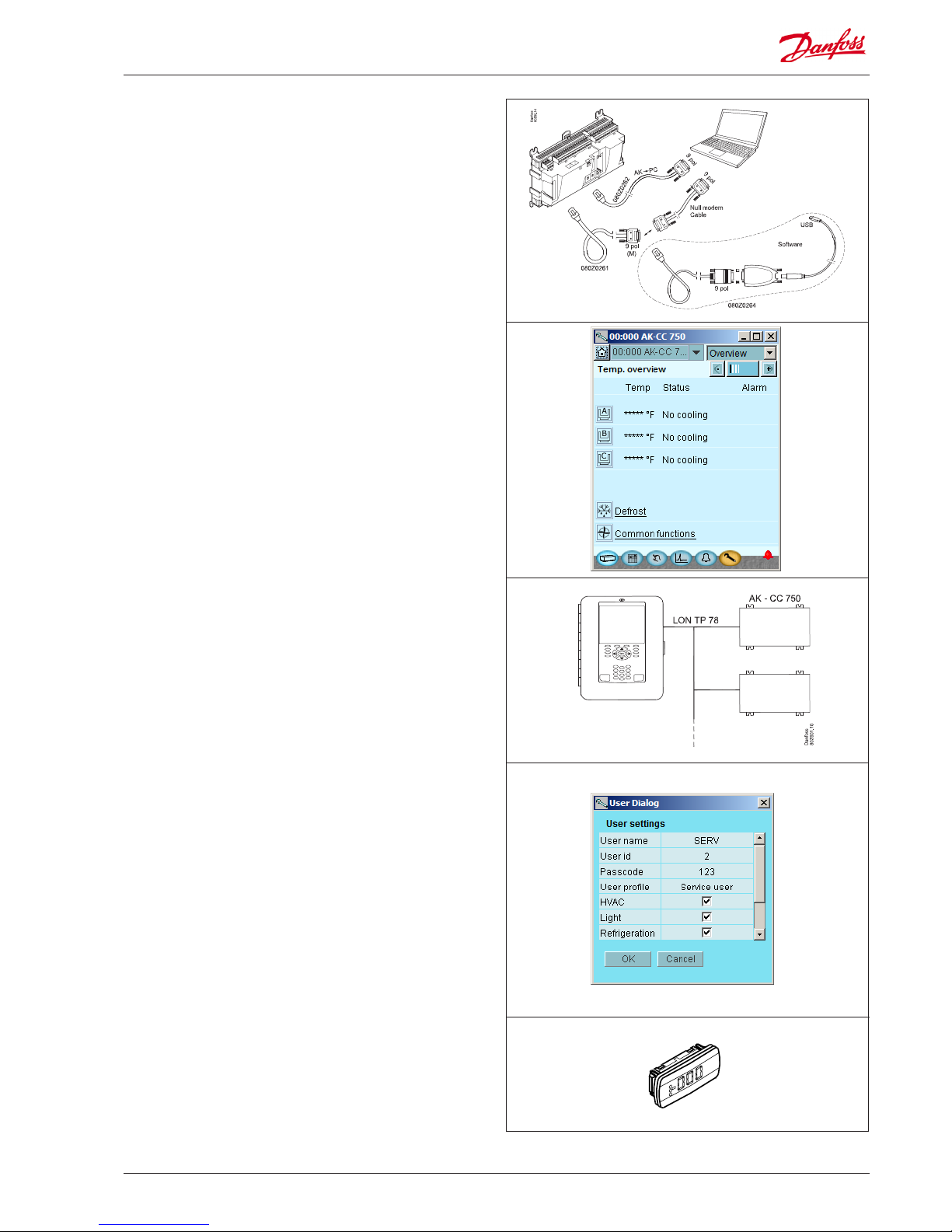
Conguration
Connect PC
PC with the program “Service Tool” is connected to the controller.
The controller must be switched on rst and the LED “Status” must
ash before the Service Tool programme is started.
Start Service Tool programme
Login with user name SUPV
Select the name SUPV and key in the access code.
When the controller is supplied the SUPV access code is 123.
When you are logged into the controller an overview of it will always
appear.
In this case the overview is empty. This is because the controller has not
yet been set up.
The red alarm bell at the bottom right tells you that there is an active
alarm in the controller. In our case the alarm is due to the fact that the
time in the controller has not yet been set.
For connecting and operating the "AK service tool" software,
please see the manual for the software.
The rst time the Service Tool is connected to a new version of a controller the start-up of the Service Tool will take longer than usual while
information is retrieved from the controller.
Time can be followed on the bar at the bottom of the display.
Page 44

44 RS8GM222 © Danfoss 10-2014 AK-CC 750 - 080Z0130 & 080Z0139
Conguration - continued
Authorization
1. Go to Conguration menu
Press the orange setup button with the spanner at the bottom
of the display.
2. Select Authorization
3. Change setting for the user ‘SUPV‘
4. Select user name and access code
5. Carry out a new login with the user name and the
new access code
To activate the new settings you must carry out a new login to the controller with the new user name and the relevant access code.
You will access the login display by pressing the "Home" at the top left
corner of the display.
This is where you can select the supervisor for the specic system and a
corresponding access code for this person.
The controller will utilize the same language that is selected in the
service tool but only if the controller contains this language. If the
language is not contained in the controller, the settings and readings
will be shown in English.
When the controller is supplied it has been set with standard authorization for dierent user interfaces. This setting should be changed and
adapted to the plant. The changes can be made now or later.
You will use this button again and again whenever you want to get to
this display.
On the left-hand side are all the functions not shown yet. There will be
more here the further into the setup we go.
Mark the line with the user name SUPV.
Press the button Change
Press the line Authorization to get to the user setup display.
Page 45

AK-CC 750 - 080Z0130 & 080Z0139 RS8GM222 © Danfoss 10-2014 45
Unlock the conguration of
the controllers
1. Go to Conguration menu
2. Select Lock/Unlock conguration
3. Select Conguration lock
Press the blue eld with the text Locked
4. Select Unlocked
Conguration - continued
The controller can only be congured when
it is unlocked.
It can only be adjusted when it is locked.
Changes to the input and output settings
are only enabled when the controller is
“Locked”
The values can be changed when it is locked,
but only for those settings that do not aect
the conguration.
3Main Switch
Used to start and stop regulation.
When the main switch is set to O, all outputs
are in standby mode and all alarms are
cancelled.
The main switch must be set to O before the
Conguration lock can be Unlocked.
Conguration lock
The controller can only be fully congured
when the conguration lock is set to Unlocked.
The settings are only applied when it is set
to Locked again. At this point, the controller
checks the functions set and compares them
with the input and output settings.
Important settings can then no longer be
changed unless the conguration is unlocked
again.
If you want to know more about the dierent conguration options, they are listed below.
The number refers to the number and picture in the
column on the left.
In general
Many settings are dependent on previous settings. This is shown by the fact that a function
can only be seen (and thus set) if an earlier
parent function allows access to this subordinate function
For example, the “Conguration lock” line will not
be shown if the main switch is set to On. Only
when the main switch is set to O, and regulation
has therefore been stopped, is it possible to set
the conguration lock.
Page 46

46 RS8GM222 © Danfoss 10-2014 AK-CC 750 - 080Z0130 & 080Z0139
System setup
1. Go to Conguration menu
2. Select System setup
3. Set system settings
Conguration - continued
3Controller name
In the rst eld you enter a name for what the
controller will be controlling.
Main frequency
Set frequency.
Alarm language
Select the language that alarm text should be
displayed in here.
Alarm text can be in a dierent language to
the operating language.
Clock
When the time is set the PC’s time can be
transferred to the controller.
When the controller is connected to a network, date and time will automatically be set
by the system unit in the network. This also
applies to change-over Daylight saving.
General
All system settings can be changed by pressing
in the blue eld with the setting and then indicating the value of the required setting.
Page 47

AK-CC 750 - 080Z0130 & 080Z0139 RS8GM222 © Danfoss 10-2014 47
Set plant type
1. Go to Conguration menu
2. Select plant type
Press the line Select plant type.
3. Set plant type
4. Other settings
After the selection of application we
will go through the other setup displays
to check whether changes will have to
be made on some of the predened
settings.
In our example we have to select a
refrigerant, (which is done on the
screen shown above) and we must
add external start/stop settings (which
is done in the subsequent “Common
functions” screen).
• Check the settings opposite the
individual functions
Conguration - continued
3Select pre-congured application
This setting give a choice between a number of predened combinations, which at the same time determine
the connection points.
At the end of the manual there is an overview of the options and connection points.
After conguration of this function, the controller will
shut down and restart. After the restart, a large number
of settings will have been made. These include the connection points. Continue with the settings and check the
values.
If you change some of the settings, the new values will
come into force.
Number of evaporators
Select the number of evaporators that you want the
controller to regulate.
Valve type
Select the relevant type of valve here.
Either AKV valve or solenoid valve (at thermostatic
expansion valve).
Refrigerant
Here you can select from a range of pre-dened refrigerants. If you cannot nd the refrigerant you want in the
list, select “User-dened”. You can then set 3 constants
which represent the refrigerant. You can obtain these 3
constants from Danfoss.
Defrost control
Select whether you want the evaporators to regulate
with defrost.
Defrost type
You can select either natural defrost or electrical defrost,
hotgas defrost or warm brine defrost.
When the installation type is to be
congured, it can be done in two
ways:
Either one of these two
In the example, we have decided
to use the second method. Here we
select:
• 3 evaporators
• AKV valve
• Refrigerant = R134a
• Defrost
• Defrost = electric
Page 48

48 RS8GM222 © Danfoss 10-2014 AK-CC 750 - 080Z0130 & 080Z0139
1. Go to Conguration menu
2. Select Common control
3. Select functions for thermostat
Conguration - continued
The setup menu has now changed.
It now shows more settings all of
which are based on the selected
plant type.
For example, earlier we selected 3
evaporators. This means that 3 sections are now displayed.
In our example we select:
• On/o thermostat
• Individual thermostat on each
section
• Night setback
• No melt function, as this is a frost
appliance
The settings are shown here in the
display.
Depending on your settings, further settings may then
be available for the selected functions.
This list in the right-hand column contains all the possible functions that may be made available in one way
or another.
If you want to know more about the individual functions than the brief description below, you will nd
additional information in Chapter 5 of the manual.
3 Thermostat type
Choose from the following thermostat functions:
• 1 valve for all /common ON-OFF thermostat
Here, only one valve is used for all evaporators. The temperature is controlled by an ON/OFF thermostat on the
basis of the settings in the A section.
• 1 valve per evap/ common ON/OFF thermostat
Here, one valve per evaporator is used. The temperature
is controlled in all evaporator sections by an ON/OFF
thermostat on the basis of the settings in the A section.
• 1 valve per evaporator / individual ON/OFF thermostat
Here, one valve per evaporator is used. The temperature
is controlled individual by ON/OFF in each evaporator
section.
• 1 valve per evaporator /individual modulating thermostat
Here, one valve per evaporator is used. The temperature is
controlled individually in each evaporator section according to a modulating principle
External reference via voltage
Select whether to use an external voltage signal for displacement of the thermostat reference.
Oset at max. signal
Oset value at max. signal (5 or 10V).
Oset at min. signal
Oset value at min. signal (0,1 or 2V).
Day/ night control
Select whether the thermostat temperature is raised for
night operation
(Night oset values must be set in the individual sections
and in Kelvin)
Night displacement via DI
Select whether night displacement is to take place with
an input signal. (Alternatively, the signal can be generated
from the internal weekly schedule or from the system
administrator via data communication.)
Thermostat band
Select whether you want the thermostat to switch between two reference settings (the values can be set in the
individual sections. (Cutout 2))
Select whether the switch should be initialised by pulse
pressure or by a switch.
Thermostat band select via DI
Select whether the reference is to be made with a signal on
a DI input.
Melt function
Select whether you want the controller to perform a melting function
Melt interval
Set the time period between two melting intervals
Melt time
Set the melting time
Denition of thermostat
Page 49

AK-CC 750 - 080Z0130 & 080Z0139 RS8GM222 © Danfoss 10-2014 49
There are several pages, one after
the other.
The black bar in this eld tells you
which of the pages is currently
displayed.
Move between the pages using the
+ and - buttons.
Conguration - continued
1. Go to Conguration menu
2. Select Section A
3. Set values for thermostat A
Press the +-button to go on to the
next page
4. Set values for alarm thermostat
5. Dene the other sections
Example:
The settings are shown here in the
display.
Denition of sections
Repeat the steps above for each
section.
In our example, the settings are the
same for all 3 sections.
3 Thermostat temperature
In the case of a common thermostat: Choose which sensors
are to be included in temperature regulation: Weighted S3AS4A, lowest of all S3s, average of all S3s, highest of all S3s,
lowest of all S4s, average of all S4s or highest of all S4s.
Air temperature S4 (discharge)Day
Sensor selection for the thermostat during day operation
At 100%, only S4 is used. At a lower value, S3 is also used
in the thermostat function. At 0%, only S3 is used in the
thermostat function.
Air temperature S4 (discharge) Night
As above, but for night operation
Cutout 1
The thermostat’s cutout temperature - Thermostat band 1
Dierential 1
Dierential on regulation according to Thermostat band 1
Cutout 2
The thermostat’s cutout temperature - Thermostat band 2
Dierential 2
Dierential on regulation according to Thermostat band 2
Night setback
Displacement of the reference during night operation
Display control
Select whether you want to connect to display type EKA
163B / EKA 164B to indicate the appliance temperature for
section A. Settings are: non, weighted S3/S4 or product
temperature sensor.
Display unit
Select whether you want temperatures and pressure displayed in SI units (°C) or US units (°F)
Display S4 (discharge) %
Sensor selection for the temperature shown on the display
At 100%, only S4 is used. At a lower value, S3 is also used. At
0%, only S3 is displayed.
Display Oset
Any oset for the display readout
S4 (discharge) Frost protection
Select whether an alarm is triggered in the case of low S4
temperature
S4 (discharge) Frost limit
Set the alarm level for the S4 sensor.
4Alarm thermostat
Select whether you want to activate the alarm thermostat
Alarm air S4 (discharge) %
Set the weighting of the S4 sensor for the alarm thermostat
High alarm limit 1
Alarm limit for high temperature alarm, thermostat band 1
High alarm limit 2
Alarm limit for high temperature alarm, thermostat band 2
High delay
Time delay for a high temperature alarm
High delay pulldown
Time delay during pull-down and after defrost
Low alarm limit 1
Alarm limit for a low temperature alarm, thermostat band 1
Low alarm limit 2
Alarm limit for a low temperature alarm, thermostat band 2
Low delay
Time delay for a low temperature alarm
Product sensor
Indicate whether a product sensor is used
High alarm limit 1
Alarm limit for high product temperature, thermostat band 1
High alarm limit 2
Alarm limit for high product temperature, thermostat band 2
High delay
Time delay for a high product temperature alarm
High delay pulldown
Time delay during pull-down and after defrost
Low alarm limit 1
Alarm limit for a low product temperature, band 1
Low alarm limit 2
Alarm limit for a low product temperature, band 2
Low delay
Time delay for a low product temperature alarm
Page 50

50 RS8GM222 © Danfoss 10-2014 AK-CC 750 - 080Z0130 & 080Z0139
Conguration - continued
1. Go to Conguration menu
2. Select Defrost function
3. Set functions
Denition of defrost functions
Example:
The settings are shown here in the
display.
If the controller’s internal defrost
schedule is used to start defrost,
the start times must be set using
the everyday user interface. See
page 61.
3 Defrost control
Select whether you want the controller to control defrost.
Defrost type
Choose a defrost method (electric / natural / hot gas or warm
brine)
Adaptive defrost
The function can be set to: "Not used"/"Monitor ice"/"Permit
cancellation of defrost for day (Skip day)"/"Skip day/
night"/"Full adaptive defrost".
Min. time between defrosts
Set how often defrosting is allowed.
Pc signal for AD (Adaptive defrost)
Choose which signal is to be followed: an internal signal (Local) or a signal via data communications (Network).
Defrost schedule
Choose which schedule is to be followed: an internal schedule or an external schedule from the system unit
Defrost start via DI
Select whether defrost should start when a signal is received
on a DI input
Max. defrost interval between defrosts
Defrost is started at the set interval if it is not started using
other methods (manual start, weekly schedule, network, DI).
If defrost is started using a schedule, “Max. interval” should be
set to a value greater than the longest period between two
defrosts in the schedule.
Fan run during defrost
Specify whether the fans should be on during defrost.
Defrost term method
Dene whether defrost is to be concluded with:
• Time
• Temperature individual in each section
• Temperature common for all sections
• DI signal individual for each section
• DI signal common for all sections
Defrost term sensor
Select the sensor that you want to give the signal for defrost
stop
Stop temperature A, B, C, D
Set the temperature at which defrost should stop
Max. defrost time
Defrost will stop after this period, even if the defrost temperature has not been reached
Min. defrost time
Defrost will run in this period, even if the defrost temperature
are reached
Pump down delay
Time delay before defrost when the uid injection stops and
the evaporator is emptied of liquid
Drip o delay
Time delay after defrost to allow water droplets to drip o
the evaporator before refrigeration is restarted
Drain delay
Delay in which the drain valve is kept open in order to ensure
pressure equalisation
Fan delay
Maximum permitted fan delay following defrost
Fan start temperature
The fans will start when the temperature at the defrost sensor falls below this value.
Drip tray heater
Set whether there is to be heating in the drip tray
Drip tray heater delay
Set heating time (time from the point at which defrost stops )
Max. Hold time
Maximum hold time that the controller will wait for the signal
to restart refrigeration (used with coordinated defrost)
Show advanced adaptive defrost
All settings for this function are expert settings.
Page 51

AK-CC 750 - 080Z0130 & 080Z0139 RS8GM222 © Danfoss 10-2014 51
Denition of common
functions
1. Go to Conguration menu
2. Select Common functions
3. Set functions in the rst display
Press the +-button to go on to the
next page
4. Set the functions in another
display
Press the +-button to go on to the
next page
Conguration - continued
Example:
The settings are shown here in the
display.
Example:
The settings are shown here in the
display.
3-
Common functions for fans and rail heat (antisweat heat)
Fan pulsing at cutout
Select whether you want the fans to pulse during the
thermostat’s cutout period. Pulsing can be restricted to
either: “night operation only” (appliance with night cover)
or “both day and night operation” (cold storage room)
Fan ON %
Set how long the fans should be ON during pulsing. Enter
as a percentage of the pulse period.
Fan duty cycle
Set the fan’s operation period for pulsing
Fan stop on S5
Select whether the fans should stop if the S5A temperature is too high. Used to stop the fans if refrigeration is not
working.
Fan stop temp.
Set the temperature limit for the S5A sensor at which the
fans stop
ASH control
Select whether to use pulsing/rail heat control. Non/Timer
or Dew point.
ASH ON at day
Set how long the rail heat should be ON for during day
operation. Enter as a percentage of the rail heat pulse
period
ASH at night
Set how long the rail heat should be ON for during night
operation. Enter as a percentage of the rail heat pulse
period.
Dew point max. limit
At a dew point above this value, rail heat is 100%.
Dew point min limit
At a dew point below this value, rail heat is controlled
with the next setting "Min ON".
ASH Min ON%
Period in which the dew point is below the min. limit.
ASH cycle time
Rail heat pulse period.
ASH during defrost
Select whether you want the rail heat to be OFF during
defrost.
4-
Common functions for compressor and case cleaning
Compressor control
Select whether you want to use compressor control
Min. ON time
Set the minimum runtime for the compressor once it has
started
Min. Restart time
Set the minimum time between the compressor stopping
and restarting
Runtime total
Set any runtime for the compressor
Case cleaning
Select whether you want an case cleaning function
Case cleaning via DI
Select whether to use a digital input to activate the case
cleaning function. Alternatively the case cleaning function
can be activated from the display or using a parameter
setting
Defrost at case cleaning
Select whether to activate the case cleaning function with
a defrost sequence. Used for frost appliances to achieve
fast defrost of the appliance before cleaning.
Appliance shutdown
Select function for light and fans when appliance shut
down
Page 52

52 RS8GM222 © Danfoss 10-2014 AK-CC 750 - 080Z0130 & 080Z0139
Conguration - continued
Example:
The settings are shown here in the
display.
5. Set the functions in the third
display
5-
Common functions for door, light etc.
Door switch mode
Select the function of any door switch. The door
switch can be used in one of the following two
ways:
• Alarm only, if the door has been left open for
too long
• Stop refrigeration and fans when the door is
open, along with an alarm if the door has been
left open for too long
Light o delay
Set how long the light should remain on after
the door has been closed (requires a light
control to be set up and controlled via the door
switch)
Restart refrig. delay
Set how long the door may be open before
refrigeration and fans are restarted. Prevents
exposure of the products to too high a temperature if someone forgets to close the door.
Door alarm delay
If the door has been open for more than the time
delay set here, a door alarm is triggered
Light control
Select whether the light should be controlled by
a door switch, a day/night signal or by a signal
via data communication
Light at Main SW = O
Choose whether the light is to be switched o
when the main switch is set to o, or if the light
is to follow the standard light control.
Control of Blinds control
Set whether the blinds are to be controlled by
a relay.
Open/close blinds via DI
Set whether the controller is to receive a signal
which activates the blinds. This must be a pulse
signal.
Forced closing via DI
Select whether a digital input is used for the
forced closing of injection
Fan at forced closing
Select whether or not you want the fans to operate during forced closing.
Alarm relay
Select the alarm relay function.
The alarm relay must be activated by alarm
priorities:
• low to high
• low to medium
• high
The alarm relay can be activated either by all
alarm priorities from low to high or only by high
priority alarms
Ext. main switch
Select whether you want a main switch via a
digital input. When the main switch is set to O,
all regulation is stopped, all outputs are set to
standby and all alarms are cancelled.
Page 53

AK-CC 750 - 080Z0130 & 080Z0139 RS8GM222 © Danfoss 10-2014 53
Conguration of inputs
and outputs
1. Go to Conguration menu
2. Select I/O conguration
3. Conguration of Digital outputs
Press the +-button to go on to the
next page
4. Setup On/o input functions
Press the +-button to go on to the
next page
Conguration - continued
The following displays will depend on the earlier denitions. The
displays will show which connections the earlier settings will require.
The tables are the same as shown earlier.
• Digital outputs
• Digital inputs
• Analog outputs
• Analog inputs
We set up the controller’s digital input functions by keying in which
module and point on this module each one of these has been connected to.
We furthermore select for each output whether the function is to be
active when the output is in pos. Closed or Open.
Load Output
Module
Point Active at
AKV A DO1 1 12 -
AKV B DO2 1 13 -
AKV C DO3 1 14 -
Fan DO4 1 15 ON
Defrost A
DO5 1 16 ON
Defrost B
DO6 1 17 ON
Defrost C DO7 1 18 ON
Anti sweat heaters DO8 1 19 ON
We set up the controller’s digital outputs by keying in which module
and point on this module each one of these has been connected to.
We furthermore select for each output whether the load is to be active
when the output is in pos. ON or OFF.
3 - Outputs
The possible functions are
the following:
AKV or solenoid valve
Defrost (el/hot gas)
Common defrost
Suction line valve
Drain valve
Drip tray heat
Night blind
Compressor
ASH
Light
Fan
Alarm
Function Input
Module
Point Active at
External start/stop AI3 2 3 Closed
Case cleaning (pulse
pressure)
AI4 2 4 Closed
Important!
An AKV function can only be set for module 1
and only for points 12, 13, 14 and 15
4 - Digital inputs
The possible functions are
the following:
Night displacement
Door alarm
Forced closing
Ext. Main switch
Thermostat band
Defrost start
Case cleaning
Appliance shutdown
Open / close Night blinds
Page 54

54 RS8GM222 © Danfoss 10-2014 AK-CC 750 - 080Z0130 & 080Z0139
5. Conguration of Analog
Input signals
Conguration - continued
We set up the analog inputs for the sensors.
5 - Analog inputs
The possible signals are the
following:
Temperature sensors:
S2 Evaporating temp.
(A,B,C,D)
S3 Air temp. before evaporator
(A,B,C,D)
S4 Air temp. after evaporator (A,B,C,D)
S5-1 Defrost sensor
(A,B,C,D)
S5-2 Defrost sensor
(A,B,C,D)
Product temperature
(A,B,C,D)
Setting:
• Pt1000
• PTC 1000
Pressure transmitters:
P0 evaporator pressure
Pc Cond. pressure
Paux 1 - 3
Setting:
• AKS 32, -1 – 6 Bar
• AKS 32R, -1 – 6 Bar
• AKS 32, - 1 – 9 Bar
• AKS 32R, -1 – 9 Bar3
• AKS 32, - 1 – 12 Bar
• AKS 32R, -1 – 12 Bar
• AKS 32, - 1 – 20 Bar
• AKS 32R, -1 – 20 Bar
• AKS 32, - 1 – 34 Bar
• AKS 32R, -1 – 34 Bar
• AKS 32, - 1 – 50 Bar
• AKS 32R, -1 – 50 Bar
• AKS 2050, 1 – 59 Bar
• AKS 2050, -1 – 99 bar
• AKS 2050, -1 – 159 bar
Voltage signals for reference
displacement:
Ext. Ref. Signal
Setting:
• 0 - 5 V,
• 1 - 5 V,
• 0 -10 V,
• 2 - 10 V
Sensor Input Module Point Type
Air temperature S3 A AI1 1 1 Pt 1000
Air temperature S3 B AI2 1 2 Pt 1000
Air temperature S3 C AI3 1 3 Pt 1000
Air temperature S4 A AI4 1 4 Pt 1000
Air temperature S4 B AI5 1 5 Pt 1000
Air temperature S4 C AI6 1 6 Pt 1000
Defrost sensor S5 A AI7 1 7 Pt 1000
Defrost sensor S5 B AI8 1 8 Pt 1000
Defrost sensor S5 C AI9 1 9 Pt 1000
Gas temperature -S2 A AI10 1 10 Pt 1000
Evaporating pressure - P0 AI11 1 11 AKS32R-12
Gas temperature -S2 B AI1 2 1 Pt 1000
Gas temperature -S2 C AI2 2 2 Pt 1000
Page 55

AK-CC 750 - 080Z0130 & 080Z0139 RS8GM222 © Danfoss 10-2014 55
Set alarm priorities
1. Go to Conguration menu
2. Select Alarm priorities
3. Set priorities for Temperature alarms
Press the +-button to go on to the next page
4. Set Alarm priorities for sensor error
Press the +-button to go on to the next page
Very many functions have an alarm connected.
Your choice of functions and settings has connected all the relevant
alarms that are current. They will be shown with text in the three
pictures.
All alarms that can occur can be set for a given order of priority:
• ”High” is the most important one
• ”Log only” has lowest priority
• ”Disconnected” gives no action
The interdependence between setting and action can be seen in the
table.
Setting
Log Alarm relay selection Net-
work
AKM dest.
Non High Low - High
High X X X X 1
Medium X X X 2
Low X X X 3
Log only X 4
Disconnected
Conguration - continued
In our example we select the settings shown here in the display
In our example we select the settings shown here in the display
Page 56

56 RS8GM222 © Danfoss 10-2014 AK-CC 750 - 080Z0130 & 080Z0139
5. Set Alarm priorities for "Various alarms"
Conguration - continued
In our example we select the settings shown here in the display
Page 57

AK-CC 750 - 080Z0130 & 080Z0139 RS8GM222 © Danfoss 10-2014 57
Lock conguration
1. Go to Conguration menu
2. Select Lock/Unlock conguration
3. Lock Conguration
The controller will now make a comparison of selected functions and dene inputs and outputs. The result can be seen in
the next section where the setup is controlled.
Conguration - continued
Press in the eld against Conguration lock.
Select Locked.
The setup of the controller has now been locked. If you subsequently
want to make any changes in the controller’s setup, remember rst to
unlock the conguration.
Page 58

58 RS8GM222 © Danfoss 10-2014 AK-CC 750 - 080Z0130 & 080Z0139
Check conguration
1. Go to Conguration menu
2. Select I/O conguration
3. Check conguration of Digital Outputs
Press the +-button to go on to the next page
4. Check conguration of Digital Inputs
Press the +-button to go on to the next page
5. Check conguration of Analog Outputs
Conguration - continued
This control requires that the setup is locked
(Only when the setup is locked are all settings for in- and outputs activated.)
An error has occurred, if you see the following:
A 0 – 0 next to a dened function.
If a setting has reverted to 0-0, you must control
the setup again.
This may be due to the following:
• A selection has been made of a combination of
module number and point number that does
not exist.
• The selected point number on the selected module had been set up for something dierent.
The error is corrected by setting up the output
correctly.
Remember that the setup must be unlocked before you can change module and point numbers..
The settings are shown on a RED background.
If a setting has turned red, you must control the
setup again.
This may be due to the following:
• The input or the output has been set up; but the
setup has later been changed so that it should
no longer be applied.
The problem is corrected by setting module
number to 0 and point number to 0.
Remember that the setup must be unlocked before you can change module and point numbers.
The setup of the digital
inputs appears as it is supposed to according to the
wiring made.
The setup of the digital
outputs appears as it is supposed to according to the
wiring made.
The setup of the Analog
inputs appears as it is supposed to according to the
wiring made.
Page 59

AK-CC 750 - 080Z0130 & 080Z0139 RS8GM222 © Danfoss 10-2014 59
Check of connections
1. Go to Conguration menu
2. Select I/O status and manual
3. Check Digital Outputs
Press the +-button to go on to the next page
4. Check Digital Inputs
Press the +-button to go on to the next page
5. Check Analog inputs
AUTO The output is controlled by the controller
MAN OFF The output is forced to pos. OFF
MAN ON The output is forced to pos ON
Before the control is started we check that all inputs and outputs have
been connected as expected.
This controls requires that the setup is locked
By means of the manual control of each output it can be checked
whether the output has been correctly connected.
Activate the various functions (e.g. the main switch).
Check that the controller registers the activation – i.e. whether the ON/
OFF value is changed in the last column.
Check the other digital inputs in the same way.
Check that all sensors show sensible values.
In our case we have no value. This may be due to the following:
• The sensor has not been connected.
• The sensor is short-circuited/interrupted
• The point or module number has not been set up correctly.
• The conguration is not locked.
Page 60

60 RS8GM222 © Danfoss 10-2014 AK-CC 750 - 080Z0130 & 080Z0139
Check of settings
1. Go to the overview
2. Select evaporator A
3. Settings for thermostat
4. Move on with the next display for the section. Here
the alarm thermostat
Press the blue overview button at the bottom left of the
display.
5. Settings for alarm thermostat
Before the control starts, we check that all the settings are as they should
be.
The overview display will now show one line for each of the general
functions. Behind each icon there is a number of displays with the
dierent settings. It is all these settings that have to be checked.
Remember the settings at the bottom of the pages – the ones that can
only be seen via the ”Scroll bar”.
Remember the settings at the bottom of the pages – the ones that can
only be seen via the ”Scroll bar”.”
Page 2 shows a summary of the temperature
sequence over the past 24
hours.
Page 61

AK-CC 750 - 080Z0130 & 080Z0139 RS8GM222 © Danfoss 10-2014 61
6. Move on with the next display for the section. Here
the expansion valve function
Press the blue overview button at the bottom left of the dis-
play..
7. Settings for the injection function
8. Repeat for Evaporator B and later again for C
,
9. Go to defrost display
Press the blue overview button at the bottom left of the display
and then press the defrost symbol
,
10. Settings for defrost
11. Go to defrost schedule
Press the schedule button to continue to the defrost schedule
Check of settings - continued
Remember the settings at the bottom of the pages – the ones
that can only be seen via the ”Scroll bar”.
Remember the settings at the bottom of the pages – the ones
that can only be seen via the ”Scroll bar”.
The settings can be reviewed in the same way as for section A.
Page 62

62 RS8GM222 © Danfoss 10-2014 AK-CC 750 - 080Z0130 & 080Z0139
In our example, the defrost schedule is set to defrost twice a
day.
12. Setup defrost schedule
13. Press a weekday and set the times for the various defrost
starts.
Use the copying functions if there are several days with
identical defrosts.
The end result with two defrosts per 24 hours can be seen here
above.
14. Go to common functions
Press the blue overview button at the bottom left of the display
and then on common functions
,
15. The settings for the common functions
Go through the individual functions.
16. The controller setup has been completed.
Check of settings - continued
Page 63

AK-CC 750 - 080Z0130 & 080Z0139 RS8GM222 © Danfoss 10-2014 63
If there is no answer from the system unit
If the Status LED does not start ashing faster than normal, the controller has not been installed in the network. The reason for this may be
one of the following:
The controller has been assigned an address out of range
Address 0 cannot be used.
The selected address is already being used by another controller or
unit in the network:
The address setting must be changed to another (vacant) address.
The wiring has not been carried out correctly.
The termination has not been carried out correctly.
The data communication requirements are described in the document:
”Data communication connections to ADAP-KOOL® Refrigeration Controls” RC8AC.
Installation in network
1. Set the address (here, for example 3)
Turn the right-hand address switch so that the arrow will point
at 3.
The arrow of the two other address switches must point at 0.
2. Push the Service Pin
Press down the service pin and keep it down until the Service
Pin LED lights up.
3. Wait for answer from the system unit
Depending on the size of the network it may be up to one
minute before the controller receives an answer as to whether
it has been installed in the network.
When it has been installed the Status LED will start to ash
faster than normal (once every half second). It will continue
with this for about 10 minutes
4. Carry out new login via Service Tool
If the Service Tool was connected to the controller while you
installed it in the network, you must carry out a new login to
the controller via the Service Tool.
Requirement to the
system unit
The system unit must be a
AK-SC 255, 355 or SM 850.
It is capable of handling
up to 120 AK controllers.
The controller has to be
remote-monitored via a
network. In this network
we assign address number 3 to the controller.
The same address must
not be used by more
than one controller in
the same network.
Page 64

64 RS8GM222 © Danfoss 10-2014 AK-CC 750 - 080Z0130 & 080Z0139
First start of control
Check alarms
1. Go to the overview
Press the blue overview button at the bottom left of the display.
2. Go to the Alarm list
Press the blue button with the alarm bell at the bottom of the
display.
3. Check active alarms
4. Remove cancelled alarm from the alarm list
Press the red cross to remove cancelled alarms from the alarm
list.
5. Check active alarm again
In our case, we have a series of alarms. We will tidy them up so that we
only have those that are relevant.
In our case an active alarm remains because the control has stopped.
This alarm must be active when control has not started. We are now
ready for the startup of control.
Please note that active plant alarms are automatically cancelled when
the main switch is in pos. OFF.
If active alarms appear when the control is started the reason for these
should be found and remedied.
Page 65

AK-CC 750 - 080Z0130 & 080Z0139 RS8GM222 © Danfoss 10-2014 65
Start the control
1. Go to Start/Stop display
Press the blue manual control button at the bottom of the
display.
2. Start control
First start of control - continued
Press in the eld against Main switch.
Select ON.
Press OK.
The controller will now start the controlling when the external
function switch is also activated to ON.
If you wish to start an extra defrost cycle, it can be done
via this display and also from the defrost screen.
Page 66

66 RS8GM222 © Danfoss 10-2014 AK-CC 750 - 080Z0130 & 080Z0139
Setup logs
1. Go to the overview
Press the blue overview button with the log symbol.
2. Log display
3. New logs
Press the +-button to go on to the next page
4. Selection of parameters
Press the +-button to go on to the next page
The top line gives access to denition of new logs and to
changes of already established logs.
The next line enables you to see a selection of the dened logs
Here is the start display for new logs
Start by dening which type of log has to be dened
Here it is determined which parameters have to be included in
the setup of data. Select a function here, then a parameter, and
nish with OK.
Page 67

AK-CC 750 - 080Z0130 & 080Z0139 RS8GM222 © Danfoss 10-2014 67
Manual defrost
1. Go to Conguration menu
2. Select defrost
3. Start defrost
If you want to carry out manual defrost, proceed as follows.
5. Log survey
6. Start the log collection
Move to the rst of the three displays and start the log collection
Here is the survey of all the parameters that are collected in the
log.
If a parameter has to be removed from the log collection, you
must select the parameter and then press Remove.
If a parameter has to be added it is done in accordance with
the earlier display
A LOG CAN ONLY BE DISPLAYED IF:
• THE CLOCK HAS BEEN SET AND
• THE CONFIGURATION IS LOCKED
Activate
Page 68

68 RS8GM222 © Danfoss 10-2014 AK-CC 750 - 080Z0130 & 080Z0139
Page 69

AK-CC 750 - 080Z0130 & 080Z0139 RS8GM222 © Danfoss 10-2014 69
5. Regulating functions
This section describes how the dierent functions work
Page 70

70 RS8GM222 © Danfoss 10-2014 AK-CC 750 - 080Z0130 & 080Z0139
Application
AK-CC 750 controllers are complete regulating units which
together with valves and sensors constitute complete evaporator
controls for refrigeration appliances and freezing rooms within
commercial refrigeration.
Generally speaking they replace all other automatic controls containing, inter alia, day and night thermostats, defrost, fan control,
rail heat control, alarm functions, light control, etc.
The controller is equipped with data communication and is operated via a PC.
In addition to evaporator control the controller can give signals to
other controllers about the operating condition, e.g. forced closing of expansion valves, alarm signals and alarm messages.
The controller’s main function is to control the evaporator so that
the system constantly operates with the most energy-friendly
refrigeration.
A specic function for registration of the need for defrost will
adapt the number of defrosts so that no energy is wasted on unnecessary defrosts and subsequent cooling-down cycles.
Among the dierent functions can briey be mentioned:
• Control of up to four evaporator sections
• Electronic injection with AKV valve
• ON/OFF or modulating temperature control
• Weighted thermostat and alarm thermostat
• Defrost on demand based on evaporator capacity
• Appliance cleaning function
• Appliance shutdown via data communication
The complete survey of controllers and functions can be seen in
the manual chapter 2 in section "Design o a evaporator control".
Examples
The controller has been designed to control one of the following
four plant types.
Through the programming you determine which one.
Evaporator control of one, two, three or four evaporators
Control of cool or defrost room
Control of cool or defrost appliance
• The refrigerant is either regulated by means of:
- expansion valve type AKV or
- solenoid valve and thermostatic expansion valve
Introduction
Page 71

AK-CC 750 - 080Z0130 & 080Z0139 RS8GM222 © Danfoss 10-2014 71
ermostat function
Valve type and thermostat
Principle
Up to 4 valves can be connected to the controller; one for every
solid state output.
It is possible to use electrically controlled expansion valves type
AKV for regulation, or else injection can take place using thermostatic expansion valves (TEV) in which the temperature is regulated using solenoid valves in the liquid line (LLSV), e.g. Danfoss
type EVR.
The thermostat function can be dened in dierent ways depending on which application it is used for. For example:
• regulation principle /
• what sensors are to be used /
• whether the user wishes to toggle between two temperature
settings, etc.
It is necessary for at least one air sensor to be tted for every evaporator section. This is applicable irrespective of which thermostat
function is selected – including "no" thermostat. The thermostat's
cut-out temperature also has to be set to the correct air temperature as this value is used by the injection function.
Thermostat type= ON/OFF
One common valve for all evaporators + common ON/OFF thermostat
A line up of refrigeration appliances which are to be regulated to
the same temperature is a typical example.
The temperature is controlled according to the ON/OFF principle
in accordance with the thermostat settings in section A.
The thermostat can control the temperature via:
• a signal from the S3/S4 sensors in section A, or
• min/max or average temperatures in all the sections used (see
the section on sensor selection).
AKV valve
This principle can also be used with electronic expansion valves
type AKV; e.g. refrigeration appliances where one valve is used for
two evaporators. These appliances are specially designed for this
application as the evaporator area is divided over two refrigeration
sections in order to achieve a consistent load over the two circuits.
One valve for every evaporator + common ON/OFF thermostat
Here, one valve is used per evaporator and the temperature is
controlled according to the ON/OFF principle in accordance with
the thermostat settings in section A
.
The thermostat can control the temperature via:
• a signal from the S3/S4 sensors in section A, or
• min/max or average temperatures in all the sections used (see
the section on sensor selection).
Page 72

72 RS8GM222 © Danfoss 10-2014 AK-CC 750 - 080Z0130 & 080Z0139
One valve for every evaporator + individual ON/OFF thermostat
Here, one valve is used per evaporator and the temperature is
controlled individually in each evaporator section according to the
ON/OFF principle.
The thermostat in every section controls the temperature via the
S3/S4 sensors in every section (where appropriate, see the section
on sensor selection).
Thermostat type = Modulating
Modulating temperature regulation maintains a more constant
temperature and also equalises the load on the system so that the
compressors have better operating conditions.
• This function can only be used on:
- central systems with AKV valves
- central systems with solenoid valves
- brine systems with solenoid valves.
• Each of the individual evaporator sections is controlled individually using a modulating thermostat function.
• Cut-out value and dierence must be set as with an ON/OFF
thermostat.
One AKV valve for each evaporator + modulating thermostat
Here, one valve is used per evaporator and the temperature is
controlled individually in each evaporator section according to the
modulating thermostat principle.
The thermostat in each section controls the temperature via the
S3/S4 sensors in each section.
During cooling and in the case of major load variations in which
the temperature falls outside of the thermostat limits, injection
is regulated so that the evaporator operates with the minimum
possible stable superheating. This ensures that the cooling process
takes place as quickly as possible.
In the case of stable loads, the thermostat will reduce the opening time for the AKV valve, so the through ow of refrigerant is
restricted to precisely the amount that is required to maintain the
temperature at the required reference (area control).
The reference temperature will be the set cut-out temperature +
half the dierence.
The cut-out temperature and dierence are set as in the case of
a standard On/O thermostat. The dierence should not be set
to less than 4°F. (In the case of a smaller dierence, load changes
could interfere with the modulating thermostat function.)
One solenoid valve for each evaporator + modulating thermostat
Here, one valve is used per evaporator and the temperature is
controlled individually in each evaporator section according to the
modulating thermostat principle.
With solenoid valves, a pulse modulating principle is used with an
adjustable period. The valve is opened and closed within a period
(e.g. 5 minutes). A PI controller calculates how long the valve
needs to be open in order to maintain the most constant temperature.
The reference temperature will be the set cut-out temperature +
half the dierence.
The cut-out temperature and dierence are set as in the case of
a standard On/O thermostat. The dierence should not be set
to less than 4°F. (In the case of a smaller dierence, load changes
could interfere with the modulating thermostat function.)
The current load on the appliance can be read o in the form of
the valve's opening time as a percentage of the set period.
Page 73

AK-CC 750 - 080Z0130 & 080Z0139 RS8GM222 © Danfoss 10-2014 73
Min. S4 /
Max. S4 /
S4 average
Min. S3 /
Max. S3 /
S3 average
Desynchronisation of valve openings
To achieve even loading on the compressors, a desynchronising
function has been built in which ensures that the times for solenoid valve opening are displaced.
Within the same controller
If several valves are used on the same controller, the opening
times are displaced in relation to one another. For example, if two
valves are used, the opening of these is displaced in relation to
one another by half a period.
Between controller
Displacement of the opening of the solenoid valves takes place
on the basis of the controllers' address settings. If a period time of
300 seconds (factory default) is used, the opening of the solenoid
valves for the A section will be displaced by 15 seconds x last digit
in the address setting, e.g.:
Addresses 0, 10, 20: are shifted by 0 seconds
Addresses 1, 11, 21: are shifted by 15 seconds, etc.
This desynchronisation between controller takes place during
start-up and once a day at around midnight, 00:00
Thermostat sensor
Individual thermostat
When individual thermostat control is used in every section, the
temperature is controlled on the basis of the air temperature sensors S3, S4 or both.
Denition of the thermostat temperature takes place using one
setting, which is based on the S4 value. With a setting of 100%,
only the S4 measurement will be used. With a setting of 0%, only
S3 will be used. With a value between 0 and 100%, both measurements will be used.
If AKV valves are used, at least one sensor must always be used
in every section, irrespective of the choice of thermostat function. This measurement is used by the injection function for the
superheat controller.
Common thermostat
When a common thermostat is used, the thermostat settings in
section A are used to control the air temperature.
The thermostat temperature can be either a weighting of the
S3 and S4 sensors in section A, as described for the individual
thermostat. This will typically be used in cold storage rooms and
freezer rooms in which several evaporators are controlled according to a common temperature.
Alternatively, the thermostat temperature can be a minimum
value, a maximum value or an average value of all S3 or S4 sensors for the refrigeration sections used. This will typically be used
where one solenoid valve is used for several appliance sections
and where it is necessary to ensure that the thermostat is taking
into account the temperature in all sections.
Address / Section
10 / A
10 / B
11 / A
11 / B
12 / A
12 / B
22 / A
22 / B
Page 74

74 RS8GM222 © Danfoss 10-2014 AK-CC 750 - 080Z0130 & 080Z0139
Swithc between two thermostat band (two references)
It is a good idea to use this function for refrigeration appliances
containing impulse purchases where the products are often
exchanged. Via a switch function it is possible to change between
two thermostat settings depending on the products contained in
the appliance. The change-over between two thermostat bands
is activated via a contact or via a pulse signal of at least three
seconds’ duration – as a rule via a key switch placed on the appliance. When the switch is activated the thermostat settings as well
as the limits for the alarm thermostat and the product sensor will
change.
The changeover between the two thermostat bands can also be
seen on the display, but only if the shift is set to take place with a
pulse signal.
When a change-over is activated the display will show to which
thermostat band the change goes.
Displacement of reference for thermostat
In refrigeration appliances there may be big load dierences
between the shop’s opening and closing hours, especially if Night
blinds/curtains are used. The thermostat reference may be raised
here without it having any eect on the product temperature.
Change-over between day and night operation can take place, as
follows:
• via the built-in weekly schedule
• via an external switch signal
• via a signal from the data communication
When night operation starts the thermostat reference will be displaced with an oset value that normally will be positive. It must
however be negative if cold accumulation is to take place.
When a Night blind is used the distribution of air in the appliance
will change radically. A change of the thermostat’s weighted S3/
S4 ratio will therefore be required. As a rule the S4 share is set at a
lower value during the night than during the day.
The thermostat reference can be displaced via an external voltage
signal which is particularly useful for process cooling.
The signal may be a 0-5V, 0-10V, 1-5V or 2-10V voltage signal. Two
oset values must be set, one indicating the displacement at minimum signal and another indicating the displacement at maximum
signal. The displacement will apply to all sections.
The displacement will not aect the alarm limits.
Melting function
This function will stop the air ow in the evaporator from being reduced by frost created by uninterrupted operation for a long time.
The function is activated if the thermostat temperature has
remained in the range between 23°F and 50°F for a longer period
than the set melting interval. The refrigeration will then be
stopped during the set melting period. The frost will be melted
so that the air ow and hence the evaporator’s capacity will be
greatly improved.
The settings for melting interval and melting period are common
to all sections, but the controller will displace the melting time for
the dierent sections so that no synchronisation will take place.
If there are several controllers in the same defrost group the time
between the two meltings should be set dierently in the individual controllers. In this way a synchronisation of the thermostats’
cutin times will be avoided.
Timer for compressor relay
If a compressor relay has been selected, the relay’s timer function
will have higher priority than the thermostat function.
Cutout 2
Cutout 1
Page 75

AK-CC 750 - 080Z0130 & 080Z0139 RS8GM222 © Danfoss 10-2014 75
Alarm thermostat
The function is used for sounding the alarm before the product
temperature at the refrigeration site becomes critical.
You can set alarm limits and time delays for high and low temperatures. Alarm will be given if the set limit is exceeded, but not until
the time delay has expired.
There will be no alarms when refrigeration has been stopped due
to cleaning of the appliance or if the main switch is set in pos. OFF.
The alarm sensor may be chosen independently of the sensor used
for the thermostat function.
Alarm sensor
The alarm sensor may be selected as either S3 or S4, or a
weighted value of both of them.
The setting is performed as a percentage value of S4.
The weighting need not be the same as for the thermostat
function. In other words, the thermostat may regulate according to S4 and the alarm thermostat may give alarm according
to S3.
Alarm limits
Dierent alarm limits can be set for the individual sections. The
alarm limits are set as absolute values in °F.
If thermostat bands are used, separate limits can be set for each
thermostat band. The alarm limits are not aected during night
operation or if there is an external reference displacement via a
voltage signal.
Time delay
Three time delays are set for alarms:
- For too low temperature
- For too high temperature during normal regulation
- For too high temperature during cooling down
• after activation of internal or external start/stop
• during a defrost
• after a power failure
• after appliance cleaning.
The time delay will apply until the actual air temperature has
dropped below the “upper alarm limit”.
Example
IN: Thermostat cut-in value
OUT: Thermostat cut-out value
Lim: Alarm limit for high temperature and low temperature
S: Alarm ceases
Curve 1: Cooling stage
(1): Time delay has been exceeded. Alarm becomes active.
Curve 2: Normal regulation where the temperature becomes too high
(2): Time delay has been exceeded. Alarm becomes active.
Curve 3: Temperature becomes too low
(3): Time delay has been exceeded. Alarm becomes active.
If regulation is carried out with two thermostat bands there will be
a set of alarm limits for each band. Time delays will be common to
the two bands.
Frost alarm
If the thermostat is controlled according to the S3 temperature
or a weighting of S3/S4, there could be a risk (on the refrigeration
shelves) that the evaporator’s S4 discharge temperature may become so cold that the products at the back of the shelves become
exposed to unintended frost temperatures.
To prevent this, the controller has a built-in frost
alarm. If the S4 temperature falls below a set frost
limit an alarm will be given so that the cause of the
cold outlet temperature can be found and corrected.
Temperature alarms
Page 76

76 RS8GM222 © Danfoss 10-2014 AK-CC 750 - 080Z0130 & 080Z0139
Fan control
To obtain energy savings it is possible to pulse control the power
supply to the fans at the evaporators.
Pulse control can be accomplished in one of the following ways:
- during the thermostat’s cutout period (cold room)
- during night operation and during the thermostat’s cutout period (appliance with Night blind)
Pulse control only takes place when
all sections/evaporators are cut out.
A period of time is set as well as the percentage of this period of
time where the fans have to be operating.
Stop of fans if cooling is missing
If the refrigeration in a breakdown situation stops, the temperature
in the cold room may rise quickly as a result of the power supply
from large fans. In order to prevent this situation the controller can
stop the fans if the temperature at S5 exceeds a set limit value.
The function can also be used as a sort of MOP function during
start-up with a hot evaporator. The fans will not start until the S5
temperature has been reached below the set limit value. In other
words, the evaporator and hence the compressor wll not be so
heavily loaded during the startup phase.
The function uses the S5 sensor from section A.
The function is not active when refrigeration has stopped.
Anti sweat heat control
It is possible to pulse-control the power to the ASH in order to save
energy. Pulse control can either be controlled according to day/
night load or dew point.
Pulse control according to day and night
Various ON periods can be set for day and night operation.
A period time is set as well as the percentage part of the period in
which the ASH is ON.
Pulse control according to dew point
In order to use this function a system manager of the type AK-SC
255 is required which can measure dew point and distribute the
current dew point to the appliance controllers. For this the ASH ON
period is controlled from the current dew point.
Two dew point values are set in the appliance control:
• One where the eect must be max. i.e.100%.
• One where the eect must be min.
At a dew point which is equal to or lower than the value, the eect
will be the value indicated in "ASH min ON%".
In the area between the two dew point values the controller will
manage the power to be supplied to the rail heat.
The current dew point and duty cycle for ASH can be read o as
status values.
If the dew point signal cannot be distributed to a controller, the
ASH will revert to day/night control.
During defrost the ASH will always be 100% ON.
If ASH ON is selected, it will run at 100% during defrost + the time
after defrost if the thermostat temperature is above the cut-in
limit (but max. 15 minutes).
Compressor control
The controller has a function that can be used for compressor
control. When the function is selected ON a relay will automatically follow the status of the thermostat functions. The relay is ON
when the thermostat demands refrigeration. If the thermostat
function is selected OFF the compressor output will constantly be
ON.
A minimum ON time and a minimum restart time for the relay
belong to the function.
The relay will be OFF during defrost.
There is display of:
- operating hours during the past 24 hours
- total number of operating hours
- number of couplings during the past 24 hours
- total number of couplings
Appliance cleaning
This function makes it easy for the shop’s sta to carry out a
cleaning of the appliance according to a standard procedure.
Function
Appliance cleaning is activated via a pulse signal of minimum
three seconds’ duration – as a rule via a key switch placed on the
appliance. It can however also be activated via data communication. Appliance cleaning is carried out via three phases:
1 - at the rst activation the refrigeration is stopped, but the fans
keep on operating in order to defrost the evaporators. ”Fan” is
shown on the display.
2 - at the second activation the fans are also stopped and the
appliance can now be cleaned. ”OFF” is shown on the display.
3 - At the third activation refrigeration is recommenced. The
display will show the actual appliance temperature.
Common functions
ASH.
Min. ON%
Eect
Dew point
Page 77

AK-CC 750 - 080Z0130 & 080Z0139 RS8GM222 © Danfoss 10-2014 77
- the light is controlled via the data communication from a system
unit.
It is possible to set whether the light is to be switched on or o
when the main controller switch is activated.
This is set in the function "Light at main switch=o".
If "Light at main switch=o" is set to ON, the normal light function
will be maintained when the main switch is switched o.
If OFF is selected for this setting, the light will stay o when the
main switch is switched o.
Night blind
Motorised night blind can be controlled automatically from the
controller. The night blinds will follow the status of the light
function. When the light is switched on, the night blinds opens
and when the light is switched o, the night blinds close again.
When the night blinds are closed, it is possible to open them using
a switch signal on the digital input. If this input is activated, the
night blinds will open and the refrigeration appliance can be lled
with new products. If the input is activated again, the blinds close
again.
When the night blind function is used, the thermostat function
can control with dierent weighting between the S3 and S4
sensors. A weighting during day operation and another when the
blind is closed.
A night blind is open when the appliance cleaning function is
activated.
Forced closing
The AKV valves can be closed with an external signal (the “Inject
ON signal”). The function must be used in connection with the
compressor’s safety circuit, so that there will be no injection of
liquid into the evaporator when the compressor is stopped by the
safety controls. (However not at low pressure – LP).
If a defrost cycle is in progress, the forced closing status will not be
re-established until the defrost is completed.
The signal can also be received from the DI-input or be received
via the data communication.
During a forced closing the fans can be dened to be stopped or
in operation.
Alarm relay
If the controller is to give alarm at a relay output, the relay must be
dened.
A setting determines when the relay is activated:
- Only for alarms with “high” priority
- For alarms with “low” and “medium” priority
- For alarms with “low”, “medium” and “high” priority.
Start/stop of regulation (main switch)
A software setting is used for starting and stopping the regulating
function.
ON = normal regulating function
OFF = Regulation stopped. All outputs will be set in standby mode.
All alarms are stopped. An alarm can however be transmitted to
the eect that regulation has stopped.
The function applies to all sections.
You can also dene an external switch for start/stop of the regulation.
If an external switch is dened regulation will only be carried out
when both switches are in position ”ON”.
To carry out cleaning of a frost appliance as quickly as possible
cleaning can be started with a defrost sequence.
When appliance cleaning is activated a cleaning alarm is transmitted to the normal alarm recipient. A later processing of these
alarms will document that the appliance has been cleaned as
often as planned. The function saves information on when the last
appliance cleaning was carried out and how long it lasted.
Appliance shutdown
This function makes it possible to shut down a refrigeration appliance using data communication or a switch signal.
When the signal is received, refrigeration stops. Fans and lights will
do the following depending on the setup:
• Fans continue. The light will follow the standard setup.
• Fans stop immediately. The light immediately switches o.
• Fans stop when the delay time expires. The light will follow the
standard light control.
• Fans stop when the delay time expires. The light switches o
when the delay time expires.
The shutdown delay time is adjustable and applies to both fans
and lights.
Any night curtain output will follow the light function.
Door contact
The door contact function can be dened for two dierent
applications:
- Door alarm
The controller monitors the door contact and delivers an alarm
message if the door has been opened for a longer period than
the set alarm delay.
- Stop of refrigeration + door alarm
When the door is opened the refrigeration is stopped, i.e. the
injection, and the fan are stopped. If the door remains open
for a longer time than the set restart time, refrigeration will be
resumed. This will ensure that refrigeration is maintained even
if the door is left open or the door contact should be defective.
If the door remains open for a longer period than the set alarm
delay an alarm will also be sounded.
In both applications the alarm function will also contain a local
reminder which is activated when 75% of the set time has been
passed. This reminder only appears on the connected display and
the intention of it is that the door must be closed before the alarm
for open door is released.
From the controller the following can be read:
- the duration of the last open period
- the total open period during the past 24 hour
- number of openings during the past 24 hours
Defrost has higher priority than the door function. That is to say,
refrigeration and fans will not be started until defrost is complete.
The door contact function can also activate the light function so
that the light is turned on and kept on for a period of time after
the door has again been closed. Cf. the section on light function.
Light function
The function can be used for controlling the light in a refrigeration
appliance or in a cold room. It can also be used for controlling a
motorised night curtain.
The light function can be dened in three ways:
- the light is controlled via a signal from a door contact. Together
with this function a time delay can be set so that the light is kept
burning for a period of time after the door has been closed.
- the light is controlled via the day/night function
Page 78

78 RS8GM222 © Danfoss 10-2014 AK-CC 750 - 080Z0130 & 080Z0139
Principle
Up to four valves can be connected. One for each solid state
output.
Control can be carried out with electrically operated expansion
valves type AKV.
Or injection can take place with thermostatic expansion valves
(TEV) where the temperature will then be regulated with solenoid
valves type EVR or similar.
Adaptive superheat with AKV valve
The evaporating temperature is measured with pressure transmitter P and the superheat with the pressure transmitter and the S2
sensor.
The function contains an adaptive algorithm that independently adjusts the valve’s opening degree, so that the evaporator
constantly delivers optimum refrigeration at lowest possible
superheat.
The superheat reference will be limited by the settings for min.
and max. superheat.
If the superheat is very low, the valve may be closed very quickly
using the "SH closed" setting.
When the superheat has dropped to 2°F over the "SH closed" limit,
this function will reduce the degree of opening of the valve so
that the valve will with certainty remain closed if the superheat
fall to the "SH closed" value. To ensure that the close function does
not generate the general superheat regulation, the "SH closed"
setting must be at least 2°F lower than "SH min".
One pressure transmitter can supply signals to several controllers
if they regulate refrigeration points on the same suction line. But if
a valve is mounted in an evaporator’s suction line, say, a KVP / KVQ
or PM, the pressure transmitter must be placed before the valve.
The signal can now only be used by the relevant controller.
Refrigerant
Before regulation can be commenced, the refrigerant must be
dened.
You can directly select one of the current refrigerants:
1 R12 11 R114 21 R407A 31 R422A
2 R22 12 R142b 22 R407B 32 R413A
3 R134a 13 Brugerdeneret 23 R410A 33 R422D
4 R502 14 R32 24 R170 34 R427A
5 R717 15 R227 25 R290 35 R438A
6 R13 16 R401A 26 R600 36 XP10
7 R13b1 17 R507 27 R600a 37 R407F
8 R23 18 R402A 28 R744 38 R1234ze*
9 R500 19 R404A 29 R1270 39 R1234yf*
10 R503 20 R407C 30 R417A
*) Only 080Z0139
If a new refrigerant is demanded which is not as yet contained
on the list you may select ”User-dened” which is subsequently
set with data for the refrigerant in question. The values can be
ordered from Danfoss.
Warning: Incorrect selection of refrigerant can cause damage to
the compressor.
MOP control
(MOP = Max. Operating Pressure)
The MOP function limits the valve’s degree of opening as long as
the evaporating temperature measured by S1 is higher than the
set MOP temperature. The function can only be active when the
AKV injection valve function is ON.
Start/stop of injection
The injection can be stopped separately for each evaporator section.
Liquid injection
Page 79

AK-CC 750 - 080Z0130 & 080Z0139 RS8GM222 © Danfoss 10-2014 79
There is a common defrost start for all evaporator sections. Defrost
stop can be common or individual when based on temperature.
Refrigeration will not be re-started until defrost has been accomplished in all sections.
Fan control during defrost
Choose whether the fans should be running or stopped during the
defrost sequence.
Coordinated defrost
If there are several controllers that are to perform defrost at the
same time they can be grouped from the system unit. The system
unit will start the defrosts, and when the defrost of the individual
controllers is later nished they will go into ”stand-by” position
until all the defrosts have been terminated. Refrigeration is then
resumed.
Drip tray heating element
It is possible to control a heating element in the drip tray for hot
gas defrost. When defrost is commenced, the heating element is
activated. The heating element remains activated until a set time
after defrost has ended by time or temperature.
Defrost type
Electric defrost
When there is electric defrost, the individual sections’ heating elements are controlled separately.
Natural defrost
Defrost is accomplished here by the fans circulating air through
the evaporator.
Warm brine defrost
Warm brine defrost can be used on indirect refrigeration systems
with solenoid valves. During warm brine defrost, the solenoid
valve is kept open during defrost so that the warm brine can run
through the "evaporator".
Hot gas defrost
During hot gas defrost, the controller regulates valves in the liquid
line, hot gas valves, a suction line valve and a drain valve.
Defrost start
Defrost can be started in several ways. Once started it will continue
until a ”defrost stop” signal is received.
- Manual defrost
Manual defrost can be enabled via a setting in the controller or
via the bottom button on the display.
After activation the setting moves back to position OFF when the
defrost has been completed.
- External signal on input
Defrost start is done with a signal on a DI input. The signal must
be an impulse signal of at least three seconds’ duration. Defrost
starts when the signal moves from OFF to ON.
- Schedule – weekly programme
Defrost can be started via an internal schedule or via an external
schedule placed in the network's system unit.
• Internal schedule
Defrost is started by means of a weekly programme that is set
in the controller. The times have relation to the controller’s
clock function. Up to eight defrosts per 24 hours can be set. The
schedule can be found via the ”Overview display” / ”Defrost” /
”Schedule”.
• External schedule
Defrost is started via a signal from the network's system unit
- Interval
Defrost starts with set intervals, e.g. every eight hours. An interval must ALWAYS be set to a "higher" value than the period set
between two defrosts when a schedule or network signal is used.
Defrost according to intervals ensures that defrost always takes
place, even if no signal is received from the network's system
unit.
- Adaptive defrost
This function can cancel planned defrosts which are not necessary, and on its own initiative it can start a defrost if the evaporator is about to be blocked by rime and ice.
(The "Adaptive defrost" function is described at the end of the
section.)
Defrost
Page 80

80 RS8GM222 © Danfoss 10-2014 AK-CC 750 - 080Z0130 & 080Z0139
Defrost sequence
Every defrost runs through the following sequence:
- emptying of evaporator (pump down) (state 1)
- defrost is initiated (state 3)
- waiting position (used for coordinated defrost) (state 4)
- drip-o (injection delay) (state 5)
- Pressure equalisation where the drain valve opens (hot gas
defrost only) (state 6)
- fan delay (state 7)
Emptying of evaporator (state 1)
Before the defrost heating elements are started it is possible to
carry out emptying of the evaporator. During a set time delay, the
valve in the liquid line remains closed, the fans run and the evaporator is drained of refrigerant.
Defrost (state 3)
• Electric defrost
The electric heating elements are activated here.
• Natural defrost
Here, the fans run in order to defrost the evaporator using air
circulation alone.
• Hot gas defrost
Here, the drain valve and suction line valve are closed. The hot
gas valve opens in order to feed hot gas through the evaporator.
• Warm brine defrost
Here, the solenoid valve is held open so that warm brine can be
fed through the evaporator.
Defrost stop
There are four kinds of defrost stop to choose from.
• Individual stop using temperature and with time as security
In the case of electric and hot gas defrost, one output per evaporator is used here, i.e. an individual heating element / hot gas
valve per evaporator.
Example of hot gas usage with individual stop per evaporator
The temperatures of each evaporator are measured using a sensor. When this temperature is then equal to or greater than the
set temperature for defrost stop, defrost stops in the section in
question. The defrost sequence continues only when all sections
have completed defrost.
When there is electric defrost, S5 is normally selected as defrost
sensor, but S3, S4 or S2 may also be selected (S3 is an air sensor
placed in the evaporator inlet, and S4 is an air sensor placed in
the evaporator outlet).
For large evaporators there should be two S5 sensors – S5-1 and
S5-2. The defrost is stopped when both temperatures have attained the set value.
If the defrost time exceeds the set max. defrost time, the defrost
stops. This will happen even if the defrost stop temperature has
not been reached (max. defrost time will function as safeguard).
When the defrost is stopped on time, the alarm message “Max.
def. period exceeded” will appear for the section in question. If
the alarm is not acknowledged within ve minutes, it will automatically be cancelled.
When there is an error in a defrost sensor, an alarm appears and
the defrost stop will then be based on time in the relevant section. Defrost stop for the remaining sections will still be based on
temperature.
• Common stop using temperature and with time as security
In the case of electric and hot gas defrost, only one output is
used for all evaporators, i.e. one output for heating element /
common hot gas valve.
Example of hot gas usage with common hot gas valve for all
evaporators
The temperatures of each evaporator are measured using a sensor. Once all the evaporator temperatures are equal to or greater
than the set temperature for defrost stop, defrosting is stopped in
all sections and the defrost sequence continues.
The selection of defrost stop sensor as well as the "safeguard"
stop on time if stop temperature can not reached is exactly as
described for individual stop.
• Stop based on time
A xed defrost time is set here. When this time has elapsed, the
defrost will be stopped and cooling will be resumed. (When stop
on time the controllers does not check whether one or more of
the evaporators still require defrost.
• Stop based DI signal
- Stop via a common DI signal
- Stop via an individual DI for each section.
• Manual stop
Defrost in progress can be stopped manually by enabling the
"Stop defrosting" function."
If a signal on forced closing during a defrost is received, the forced
closing status will not appear until the defrost has been nished.
Coordinated defrost (state 4)
Via a system unit it is possible to perform a group defrost with
other appliance controllers. The system unit will in that case start
a defrost with a start signal via the data communication. When the
Page 81

AK-CC 750 - 080Z0130 & 080Z0139 RS8GM222 © Danfoss 10-2014 81
rst section of a controller has nished defrost, the controller starts
the “Max. hold time” function and when all sections have nished
defrost, this is recorded by the system unit. The controller will
then move into waiting position until it receives a signal to restart
refrigeration. This happens when all controllers in the group have
concluded their defrosts. If this message has not been received
within the “Max. holding time” time, the controller will resume
refrigeration under all circumstances.
Drip-o delay (state 5)
A time delay can be put in so that any drops of water may drip
o the evaporator before refrigeration is resumed. In this way it is
ensured that the evaporator as far as possible is free from water
when refrigeration is restarted.
Drain delay / pressure equalisation during hot gas defrost
(state 6)
When the drip delay is completed, it is possible to add a drain
delay in which the smaller drain valve opens up to the suction line
so that pressure equalisation takes place. Once the drain delay has
expired, the main valve in the suction line opens and cooling is
resumed.
Delayed fan start (state 7)
Regardless of whether the fans are running or have stopped
during the defrost sequence, the fans can be stopped during this
delay.
Drops of water left on an evaporator after defrost should be bound
to the evaporator (primarily used in freezing rooms).
After defrost, the liquid injection is started, the evaporator is
cooled down, but the fans will be started a little later. During this
period the controllers operate the expansion valve by force, but
they constantly monitor the superheat.
The temperature at which the fans are to be started is set (measured always with the S5 sensors). The max. permissible time delay
in minutes is set.
The time delay for fan start will not commence until the time delay
for liquid injection, if applicable, has run out.
Only when all the S5 sensors register a lower temperature than the
set will the fans be started. If all S5 sensors do not register a lower
temperature than the set by the delay time has elapsed, the fans
will start. At the same time alarm is given that Maximum delay
time for fan is exceeded for the section in question. If the alarm
is not acknowledged within ve minutes, it will automatically be
cancelled.
If some of the S5 sensors are defective, the signal from sensors that
remain intact will be used.
Example
Below is an example of a defrost sequence using hot gas defrost.
The following are used in the example:
- Hot gas defrost with common hot gas valves
- Defrost using the evaporators is stopped individually using the
S5 temperature
- The fans are stopped during defrost
The defrost sequence will be as follows:
• Pump down (state 1)
The AKV valve closes, the heating element in the drip tray is
activated and the fans run.
• Defrost (state 3)
The fans stop, the main valve and the drain valve in the suction
line are closed and the hot gas valve opens.
Defrost is terminated when the S5 sensor has reached its stop
temperature.
• Hold (state 4)
If coordinated defrost is being used, the controller will wait for
a release signal from the network's system unit before continuing with the sequence. Alternatively, the hold stops once the
maximum hold time has expired.
• Drip delay (state 5)
Cooling is delayed so that any drops of water can run o the
evaporator.
• Drain delay / pressure equalisation (state 6)
The drain valve opens so that pressure equalisation takes place
in the evaporator.
• Fan delay (state 7)
The main valve in the suction line opens and liquid injection is
resumed. The fans are delayed so that the remaining drops of
water are bound to the evaporator. The fans start when the required fan start temperature has been reached on the S5 sensor,
or when the set delay time has expired.
Page 82

82 RS8GM222 © Danfoss 10-2014 AK-CC 750 - 080Z0130 & 080Z0139
• Drip tray heating element
The drip tray heating element is switched o when the set delay
time has expired. This delay time is applicable from the end of
defrost (state 3).
Adaptive defrost
This function can cancel planned defrosts which are not necessary, and on its own initiative it can start a defrost if the evaporator is about to be blocked by rime and ice.
This function is based on a registration of the air ow through
the evaporator. By using the AKV valve as mass owmeter for the
refrigerant ow it is possible to compare the energy admission
on the refrigerant side with the energy emission on the air side.
Via this comparison the air ow through the evaporator can be
determined and hence also the amount of ice/frost build-up on
the evaporator surface.
Automatic adaptation to the evaporator
When adaptive defrost is activated it will carry out an automatic
tuning in order to adapt itself to the relevant evaporator. The rst
tuning takes place after the rst defrost so that tuning can be carried out on an evaporator without ice/rime formation. New tuning
subsequently takes place after each defrost (but not at night with
night blinds). In a few cases it may happen that the function is not
correctly adapted to the relevant evaporator. This is usually because the automatic adjustment has been made under abnormal
operating conditions at start-up/on testing the system. This will
result in the function reporting an error state. If this happens, a
manual reset of the function should take place while briey setting the function switch to "OFF".
Status display
For each evaporator it is possible to display the current operating
status for adaptive defrost:
0: OFF Function not activated
1: Error Reset to be carried out
2: Tuning Function carries out automatic tuning
3: OK - no ice build-up
4: Slight ice build-up
5: Medium ice build-up
6: Heavy ice build-up
Restrictions and sensor signals:
The following connections/signals must be used:
- Expansion valve type AKV
- Temperature signal from both S3 and S4
It is essential that the S3 and S4 sensors are located in the air
ows of the evaporator inlet and evaporator outlet. The sensors
must be mounted in such a way that the eects of external heat
sources, such as fan motors, are minimised as far as possible.
- Pressure signal from condensation pressure Pc
The Pc signal can be received from a pressure transmitter which
is connected to the controller, or it may be received via data
communications from the system unit.
(Several controllers may share the same Pc signal.)
If the controller does not receive a Pc signal, it will use a constant
value for the condensation pressure.
- Adaptive defrosting cannot be used if one of the following refrigerants are used for regulation: R23, XP10, R13B1 or user-dened.
This function can only cancel planned defrosts which start from
a defrost schedule – either an internal schedule or an external
schedule in the system unit. Other defrost start signals will always
result in defrost.
This function will only cancel defrost if all evaporator sections so
permit.
Function selection
This function can be set to operate in one of the following ways:
0. OFF:
The function is stopped. Any alarms are removed and the function is reset.
1. Monitoring only::
The function is used exclusively to monitor the formation of
ice on the evaporator – the function will not cancel planned
defrosts.
If the function detects severe ice/rime formation on an evaporator, an alarm "Appliance A – air ow reduced" is transmitted.
The alarm is removed at the start of the next defrost.
2. Skipping of defrosts by day (appliances with night blinds)
This setting is used if function is only to cancel unnecessary
defrosts by day, and if night blind is used for the appliance.
This function undertakes new tuning only when defrost takes
place during day operation.
The controller MUST be set to night state when night time cover
is set for the appliance – this may take place via a schedule in
the controller or alternatively via a signal from the system unit.
This is because there is a risk of the function detecting the
formation of rime/ice on the evaporator when night blind is set
for the appliance. (A greater reduction in air ow may occur as
a consequence of a small distance between night blinds and
products.
It is important for night time cover to be removed from the
appliance when the controller switches to day operation. If not,
there is a risk of incorrect tuning, and hence missing data for
cancelling defrosts. Correct tuning will take place only after the
next defrost.
3. Skip defrost day and night (refrigeration rooms and appliances
without night blind)
This setting is used if the function is to cancel defrosts for rooms
and appliances without night blind.
New tuning of the function takes place after each defrost.
4. Full adaptive defrost
This setting is used if the function is to start defrosts on its
own initiative. The setting can ideally be used in refrigeration/
frost rooms where the time of defrost is not as important. In
refrigeration/frost rooms, this setting can ensure major savings
as defrosts take place only when necessary. Scheduled defrosts
will always be carried out. That is to say, a basic schedule can
be input and the adaptive function will then start extra defrosts
itself where necessary..
Minimum time between defrosts
It is possible to enter a minimum time between defrosts. In this
way it can be avoided that planned defrosts according to the
weekly schedule be carried out immediately after the termination
of a adaptive defrost. The time span is from the termination of a
adaptive defrost and until a planned defrost is again allowed.
Documentation on saving
It is possible to read the number of planned defrosts and the
number of cancelled defrosts.
Page 83

AK-CC 750 - 080Z0130 & 080Z0139 RS8GM222 © Danfoss 10-2014 83
Alarms
• Appliance not defrosted
If this function detects ice formation shortly after defrost, the
"Appliance not defrosted" alarm is generated. This error may be
due to the evaporator not being defrosted correctly as a consequence of faults in heating elements or fans. After this alarm, the
function will not cancel defrosts.
This alarm is removed at the start of the next defrost, at which
point cancellation of defrosts will be permitted again.
• Air ow reduced
If this function detects severe ice formation on the evaporator,
the alarm "Appliance X – air ow reduced" is transmitted. This error will typically be due to severe ice formation on the evaporator, but it may also be due to reduced air ow as a consequence
of severe over stacking of goods or dropout of fans. After this
alarm, the function will not cancel defrosts.
This alarm is removed at the start of the next defrost, at which
point cancellation of defrosts will be permitted again.
• Sensor error
The controller cannot carry out a tuning calculation for use in
the adaptive defrosting.
After this alarm, the function will not cancel defrosts.
This alarm is removed at the start of the next defrost, at which
point cancellation of defrosts will be permitted again.
• Flash gas alarm
This function will monitor whether there is any ash gas at the
expansion valve. If ash gas is detected over a fairly long period,
the alarm "Appliance X – Flash gas alarm" is triggered.
This alarm is removed when ash gas disappears or at the start
of the next defrost.
Page 84

84 RS8GM222 © Danfoss 10-2014 AK-CC 750 - 080Z0130 & 080Z0139
Miscellaneous
Alarm priorities
The dierent alarms that can be generated by the controller can
be given a priority.
“priority” will activate the alarm relay if it has been so dened. The
alarms are entered in the alarm log and also transmitted to the
data communication if connected.
The “Log only” priority will as mentioned only be entered in the
alarm log.
Setting Log Selection Alarm relay Net
work
AKM dest.
Non High Low-Middle
Low -
High
High X X X X 1
Medium X X X X 2
Low X X X X 3
Log Only X 4
Disabled
Sensor correction
The input signal from all connected sensors can be corrected. A
correction will only be necessary if the sensor cable is long and has
a small cross-sectional area. All displays and functions will reect
the corrected value.
Clock function
The controller contains a clock function, that can be used together
with schedules for defrost and day/night operation.
In case of power failure the clock must be reset.
If the controller is linked up to a System Manager via the data communication, the System Manager will reset the clock.
Signals via data communication
The controller contains a number of functions that can be activated/overridden by the network’s system unit:
Night operation
The day/night operation of the individual controllers can be controlled from a central weekly schedule in the system unit.
Interruption of injection
The system unit can ensure that all appliance and room controllers
force-close their AKV valves if all compressors in the belonging
central plant stop due to operation breakdowns and are prevented
from starting again.
Light control
In appliance controllers the light can be controlled via a central
weekly schedule in the system unit.
Coordinated defrost
Several appliance controllers can be grouped in the system unit
so that they will start a defrost at the same time and subsequently
start up after defrost at the same time.
Adaptive defrosting
By using the "Adaptive Defrosting" function the controller must receive a condensing pressure signal Pc. This signal must be received
from the System Manager.
Optimization of suction pressure
The appliance/room controllers can supply the necessary information to the system unit so that it can optimise the suction pressure
based on the appliance with the heaviest load.
Forced refrigeration
The controller will undertake refrigeration when this signal is
received. Refrigeration will continue until the signal is removed.
Sensor correction
The input signal from all connected sensors can be corrected.
Anti sweat heaters
The anti sweat heater control can be overridden.
Display signal
The air temperatures measured at the evaporator can be read from
a display. This display must be of display type EKA 163B or EKA
164B. The display is normally mounted on the appliance so that
the customer can see the air temperature. Up to four displays per
controller can be tted.
Connection is eected by means of wires with plug connectors.
The display can be placed on an appliance front, for example.
When a display with operating buttons is selected, the unit can be
operated with ease by means of a menu system as well as displaying temperatures and operating situations.
Display signal
Temperature display can be selected for a product sensor, or
alternatively a weighted condition between air sensors S3 and S4.
Setting is expressed as a percentage of the S4 signal.
The display is independent of the thermostat function.
An Oset can be set for the display.
Values are displayed by means of three digits, and one setting
allows you to decide whether the temperature is to be displayed
in °C or °F.
LEDs on the front
The LEDs will come on when the associated relay is activated:
2nd LED = refrigeration
3rd LED = defrost
4th LED = ventilator operational
The LEDs will ash when an alarm has been triggered.
In this situation, you can call up the error code on the display by
briey pressing the top button.
The buttons
When you want to change a setting, the top and bottom buttons
will give a higher or a lower value depending on which button
you press. Before you can change the value, you must access the
menu. This is done by holding down the top button for a couple
of seconds; this takes you into the list of parameter codes. Find the
parameter code you want to change, then press the centre button to display the parameter value. When you have changed this
value, save the new value by pressing the centre button again
Examples:
Setting a menu
1. Press the top button to display a parameter
2. Press the top or bottom button and nd the parameter you
want to set
3. Press the centre button to display the value
4. Press the top or bottom button and set the new value
5. Press the centre button again to save the value.
Page 85

AK-CC 750 - 080Z0130 & 080Z0139 RS8GM222 © Danfoss 10-2014 85
.
Setting the temperature
1. Press the centre button to display the temperature setting
2. Press the top or bottom button and set the new value
3. Press the centre button to save the setting.
Read the temperature at the defrost sensor)
• Briey press the bottom button
Manual start or stop of defrost
• Press the bottom button for 4 seconds.
Read codes
Normally the selected temperature signal can be read from the
display, but under certain conditions the display may show other
codes in order to notify the user of various operating states.
Function Display read
Main switch When the "main switch" is set to OFF, the display will
read "OFF"
Defrost During defrost, the display will read "-d-".
The display will switch to normal temperature display
when the thermostat temperature is in place, or the
delay period “High temp alarm delay” has expired .
Case cleaning
When appliance cleaning is activated, the display will
read "Fan" to indicate that the fans are running in order
to defrost the evaporator. When the second stage of appliance cleaning is activated, the display reads "OFF" in
order to indicate that the appliance can now be cleaned
as all outputs are in standby position.
PAS Requirement for access code. If operation of the display
is to be protected by an access code, both the denition and the access code must be set in the controllers'
authorisation menu for the local display (LOCD).
Alarm The three LED's will ash if an alarm is triggered. The
alarm code can be viewed by pressing the top button.
- - - When three dashes appear, the valid temperature reading is faulty (sensor switched o or short-circuited), or
else the display has been deactivated.
th1/th2 When the thermostat bank is changed by pressing a
button, the display will display for 10 seconds which
thermostat band is active.
- - 1
- - 2
Initiation, Display is connected to output A
Output B. etc.
Get o to a good start when use of display
The following procedure will start regulation as quickly as possible:
1. Open parameter r12 and stop regulation (in a new appliance not
set previously, r12 will already be set to 0, which means regulation stopped)
2. Open parameter o93 and set the conguration lock to a value of
0 (=OFF)
3. Open parameter 062 = Select a predened use on the basis
of the electrical connections which appear at the end of the
manual. After conguration of this function, the controller will
shut down and restart.
4. Once the controller has restarted, open parameter 093 and the
conguration lock is opened = value 0.
5. If AKV valves are used, you must also select refrigerant via
parameter o30.
6. Open parameter r12 and start regulation.
7. When there is a network: set the address for the address switch
in the controller.
8. Send this address to the system unit by activating a service pin.
Menu overview:
A display can be connected for each evaporator section. In each
display, the following settings/readings can be undertaken for the
evaporator section in question.
Parameter
name
Function At start-
up
r12 Main switch:
0: Controller stopped
1: Regulation
x
r22 Select thermostat band:
1 = Thermostat band 1 is active
2 = Thermostat band 2 is active
r37 Setting of cut-out value for the thermostat in section
A/B/C/D
r38 Setting of cut-out value for thermostat band 2
o30 Setting of refrigerant (must be set if AKV valves are
used)
0= not selected, 1=R12. 2=R22. 3=R134a. 4=R502.
5=R717. 6=R13. 7=R13b1. 8=R23. 9=R500. 10=R503.
11=R114. 12=R142b. 13=User def. 14=R32. 15=R227.
16=R401A. 17=R507. 18=R402A. 19=R404A.
20=R407C. 21=R407A. 22=R407B. 23=R410A.
24=R170. 25=R290. 26=R600. 27=R600a. 28=R744.
29=R1270. 30=R417A. 31=R422A. 32=R413A.
33=R422D. 34=R427A. 35=R438A. 36=XP10.
37=R407F. 38*=R1234ze. 39*=R1234yf.
*) Only 080Z0139
x
o46 Case cleaning function. Set:
0: Case cleaning not started
1: Only fan running (evaporator defrost)
2: All outputs are OFF (cleaning may be carried out)
o62 Selection of predened conguration.
This setting will give a choice from a series of predened combinations, which at the same time establish
the connection points.
At the end of the manual there is an overview of the
options and connection points.
After conguration of this function, the controller will
shut down and restart.
x
o93 Conguration lock
You can only select a preset conguration or change
refrigerant when the conguration lock is open.
0 = Conguration open
1 = Conguration locked
x
u17 Actual air temperature for the thermostat in section
A/B/C/D
u20 Actual temperature at S2 sensor. Section A/B/C/D
u21 Actual superheat. Section A/B/C/D
u24 AKV valve opening degree. Section A/B/C/D
u26 Actual evaporating temperature. Section A/B/C/D
u36 Actual air temperature for product sensor in section
A/B/C/D
u68 Actual air temperature for alarm thermostat in sec-
tion A/B/C/D
X = When the controller is not set up, the display will only read the marked settings
Page 86

86 RS8GM222 © Danfoss 10-2014 AK-CC 750 - 080Z0130 & 080Z0139
The controller oers quite a number of status displays which
are invaluable in connection with operational start-up and
optimisation.
Thermostat function
Display of S3 air admission
Display of S4 air emission
Display of weighted S3/S4 thermostat temperature
Min., Max. and Average thermostat temperature / 24 hours
Average thermostat coupling in % / 24 hours
Running time for cutin period in progress or for the last cutin
period
Alarm thermostat
Display of weighted S3/S4 alarm temperature
Min., Max. and Average alarm temperature / 24 hours
Percentage of time where the alarm temperature was outside the
limits / 24 hours
Product sensor
Display of the temperature at the product sensor
Min., Max and Average of product temperature / 24 hours
Percentage of time where the product temperature was outside
the limits / 24 hours
Injection function
AKV opening degree in %
Average opening degree / 24 hours
Evaporating pressure
S2 gas temperature
Superheat
Superheat reference
Defrost
Actual defrost status
Degree of icing-up of evaporator
Duration of on-going or last defrost
Average duration of the last ten defrosts
Duration of cooling-down after defrost
Defrost sensor temperature
Number of planned and skipped defrosts
Compressor
Operating time last 24 hours
Total operating time
Number of couplings last 24 hours
Total number of couplings
Door contact
Door contact status
Duration of last opening
Number of openings last 24 hours
Opening time last 24 hours
Rail heat
Dew point
Actual duty cycle
Appliance cleaning
Time of last cleaning
Duration of last cleaning
Information
Input and output status
Status display of all inputs and outputs
Manual overriding of all outputs
Regulating status
The controller goes through some regulating situations. You can
see the actual situation here.
When operating with AK-ST the text is written on the screen for
the section. When operating from AKM the operating status is a
numerical value.
The values are, as follows:
0: Refrigeration stopped from Main Switch
1: Start-up phase for the injection function
2: Adaptive regulation of the superheat
3: 4: Defrost
5: Start-up after defrost
6: Forced closing
7: Injection function failure
8: Sensor error and emergency refrigeration
9: Modulating thermostat control
10: Melting function is active
11: Open door
12: Case cleaning
13: Thermostat cutout
14: Forced refrigeration
15: Shut down
Defrost state
During and immediately after a defrost the defrost status will be:
1: Evaporator is emptied
3: Defrost
5: Evaporating pressure is lowered
6: The liquid injection is delayed
7: Fan delay
Installation considerations
Accidental damage, poor installation, or site conditions, can give
rise to malfunctions of the control system, and ultimately lead to a
plant breakdown.
Every possible safeguard is incorporated into our products to
prevent this. However, a wrong installation, for example, could still
present problems. Electronic controls are no substitute for normal,
good engineering practice.
Danfoss wil not be responsible for any goods, or plant components, damaged as a result of the above defects. It is the installer’s
responsibility to check the installation thoroughly, and to t the
necessary safety devices.
Particular attention is drawn to the need for a “force closing” signal
to controllers in the event of compressor stoppage, and to the
requirement for suction line accumulators.
The controller is not built for use on plate heat exchangers.
NH3 + AKVA
Please contact Danfoss if you require help concerning the positioning of sensors, transmitters, etc.
Your local Danfoss agent will be pleased to assist with further
advice, etc.
Page 87

AK-CC 750 - 080Z0130 & 080Z0139 RS8GM222 © Danfoss 10-2014 87
Page 88

88 RS8GM222 © Danfoss 10-2014 AK-CC 750 - 080Z0130 & 080Z0139
Alarm texts
Setting of priority Default
priority
Alarm text Description
Temperature alarms
High air temp. A High High air temp. (A,B,C,D) The air temperature has been above the high alarm limit for longer time than set delay
Low air temp. A High Low air temp. (A,B,C,D) The air temperature has been below the low alarm limit for longer time than set delay
Frost protect A High Frost protection, too low S4
(A,B,C,D)
The air o temperature (S4) is below the set frost protection limit
High Prod. temp. A High High Prod. temp. (A,B,C,D) The product temperature has been above the high alarm limit for longer time than set delay
Low prod. temp. A High Low prod. temp. (A,B,C,D) The product temperature has been below the low alarm limit for longer time than set delay
Same for B,C,D
Sensor errors
Pe sensor error Low Po sensor error Pressure transmitter signal for evaporating pressure faulty
S2A sensor error High S2A sensor error (B,C,D) S2A temp. sensor signal faulty
S3A sensor error High S3A sensor error (B,C,D) S3A temp. sensor signal faulty
S4A sensor error High S4A sensor error (B,C,D) S4A temp. sensor signal faulty
S5-1A sensor error High S5-1A sensor error (B,C,D) S5-1A temp. sensor signal faulty
S5-2A sensor error High S5-2A sensor error (B,C,D) S5-2A temp. sensor signal faulty
Prod. sensor error A High Product temp. A sensor error
(B,C,D)
Product temp. sensor signal faulty
Same for B,C,D
Pc sensor error High Pc sensor error Pressure transmitter signal for condensing pressure faulty
Various alarms
Standby mode Medium Control stopped,
MainSwitch=OFF
The control has been stopped via the setting ”Main switch” = ON or via the external Main switch
input
Refrigerant changed Low Refrigerant changed The refrigerant setting has been changed
Case cleaning High Case cleaning initiated A case cleaning has been initiated
Door open pre alarm Low Door open pre alarm The door has been open for longer time than 75% of the set alarm delay
Door open alarm Medium Door open alarm The door has been open for longer time than set alarm delay
Injection problem A,
B, C, D
Medium Injection problem (A,B,C,D) The AKV valve can not control the superheat of the evaporator
Max def period A,B,C,D Low Max defrost time exceeded
(A,B,C,D)
The last defrost cycle has terminated on time instead of temperature
Max fan del exceeded
A,B,C,D
Low Max fan del ay time exceeded
(A,B,C,D)
The fans have been started on time instead of temperature after a defrost
Max hold time A,B,C,D Low Max defrost hold time
(A,B,C,D)
After a defrost cycle the evaporator has restarted cooling as it did not get a release signal via the
defrost co-ordination setup in the network manager (AKA gateway)
Air ow alarm A,B,C,D Low AD - Case X - Air ow reduced The air ow at the evaporator is greatly reduced – either as a consequence of severe ice formation, a
fan fault or other obstruction.
AD – Case A not defrosted (B,C,D)
Low AD - Case X not defrosted The air ow is continuously reduced after defrost has been carried out
AD – Fault case A,B,C,D Low AD - Sensor error A,B,C,D Tuning problem in adaptive defrost
AD – Flash gas evapora.
A,B,C,D
Low AD – Flash gas detect A,B,C,D Flash gas has been detected at the valve for a relatively long time
Page 89

AK-CC 750 - 080Z0130 & 080Z0139 RS8GM222 © Danfoss 10-2014 89
System alarms
The alarm priority can not be altered on system alarms
Medium Clock has not been set Time has not been set
Medium System Critical exception A unrecoverable critical system failure has occurred – exchange the controller
Medium System alarm exception A minor system failure has occurred – power o controller
Medium Alarm destination disabled When this alarm is activated the alarm transmission to the alarm receiver has been deactivated.
When the alarm is cleared the alarm transmission to the alarm receiver has been activated.
Medium Alarm route failure Alarms can not be transmitted to alarm receiver – check communication
High Alarm router full The internal alarm buer has an overrun – this might occur if the controller can not send the alarms
to the alarm receiver. Check communication between controller and AKA gateway.
Medium Device is restarting The controller is restarting after ash updating of the software
Medium IO module error There is a communication fault between the controller module and the extension modules – the
fault must be corrected as soon as possible
Low MAN DI………. The output in question has been put in manual control mode via the AK-ST 500 service tool soft-
ware
Low MAN DO……… The output in question has been put in manual control mode via the AK-ST 500 service tool soft-
ware
Page 90

90 RS8GM222 © Danfoss 10-2014 AK-CC 750 - 080Z0130 & 080Z0139
Function
The controller has a setting where you can
choose between various types of installation. If
you use these settings, the controller will suggest
a series of connection points for the dierent
functions. These points are shown below.
Even if your installation is not 100% as described
below, you can still use the function. After use,
you need only adjust the divergent settings.
The given connection points in the controller can
be changed if you wish.
Appendix - Recommended
connection
Comments Quick Setup IO Assignments
1 4 Case
LnUp LT C
AI Points (Base Module)
1-1 1-2 1-3 1-4 1-5 1-6 1-7 1-8
Disc Air A Disc Air B Disc Air C Disc Air D Def Term A Def Term B Def Term C Def Term D
DO Points (Base Module)
1-12 1-13 1-14 1-15 1-16 1-17 1-18 1-19
Sol Valve
2 4 Case
LnUp MT C
AI Points (Base Module)
1-1 1-2 1-3 1-4 1-5 1-6 1-7 1-8
Disc Air A Disc Air B Disc Air C Disc Air D
DO Points (Base Module)
1-12 1-13 1-14 1-15 1-16 1-17 1-18 1-19
Valve A
3 4 EEV LT AI Points (Base Module)
1-1 1-2 1-3 1-4 1-5 1-6 1-7 1-8
Disc Air A Evap Out A Def Term A Disc Air B Evap Out B Def Term B Disc Air C Evap Out C
DO Points (Base Module)
1-12 1-13 1-14 1-15 1-16 1-17 1-18 1-19
EEV A EEV B EEV C EEV D Fa n Light Def ASH
4 4 EEV LT I
Term
AI Points (Base Module)
1-1 1-2 1-3 1-4 1-5 1-6 1-7 1-8
Disc Air A Evap Out A Def Term A Disc Air B Evap Out B Def Term B Disc Air C Evap Out C
DO Points (Base Module)
1-12 1-13 1-14 1-15 1-16 1-17 1-18 1-19
EEV A EEV B EEV C EEV D Fa n Light Def ASH
5 Uncon-
nected DOs
(OK)
4 EEV LT
NoTerm
AI Points (Base Module)
1-1 1-2 1-3 1-4 1-5 1-6 1-7 1-8
Disc Air A Evap Out A Disc Air B Evap Out B Disc Air C Evap Out C Disc Air D Evap Out D
DO Points (Base Module)
1-12 1-13 1-14 1-15 1-16 1-17 1-18 1-19
EEV A EEV B EEV C EEV D Fa n Light Def ASH
6 4 EEV LT C
Term DI
AI Points (Base Module)
1-1 1-2 1-3 1-4 1-5 1-6 1-7 1-8
Disc Air A Evap Out A DI Term A Disc Air B Evap Out B DI Term B Disc Air C Evap Out C
DO Points (Base Module)
1-12 1-13 1-14 1-15 1-16 1-17 1-18 1-19
EEV A EEV B EEV C EEV D Fa n Light Def ASH
7 4 EEV LT I
Term DI
AI Points (Base Module)
1-1 1-2 1-3 1-4 1-5 1-6 1-7 1-8
Disc Air A Evap Out A DI Term A Disc Air B Evap Out B DI Term B Disc Air C Evap Out C
DO Points (Base Module)
1-12 1-13 1-14 1-15 1-16 1-17 1-18 1-19
EEV A EEV B EEV C EEV D Fa n Light Def A ASH
Descriptions:
'EEV' = electronic expansion valve
'LLSV' = liquid line solenoid valve
'LT' = low temp
'MT' = medium temp
'LnUp' = Line Up
'I Term' = individual termination (sensor)
'C Term' = common termination (sensor)
'I Term DI' = individual termination, digital input
'C Term DI' = common termination, digital input
'CPM' = case power module
'Comm Term' = common termination (sensor)
'Ind Term' = individual termination (sensor)
'AD C Term' = adaptive defrost, common termination
(sensor)
'AD I Term' = adaptive defrost, individual termination
(sensor)
'DT C Term' = dual temp, common termination (sensor)
'DT I Term' = dual temp, individual termination (sensor)
Page 91

AK-CC 750 - 080Z0130 & 080Z0139 RS8GM222 © Danfoss 10-2014 91
1-9 1-10 1-11
Door Sw
Power Module Connector
1-20 1-21 1-22 1-23
ASH Light Def Fan
1-9 1-10 1-11
Door Sw
Power Module Connector
1-20 1-21 1-22 1-23
ASH Light Def Fan
AI Point (Expansion Module)
1-9 1-10 1-11 2-1 2-2 2-3 2-4 2-5 2-6 2-7 2-8
Def Term C PE Pressure Door Sw Disc Air D Evap Out D Def Term D Dual-Temp
DO Point (Expansion Module)
2-9 2-10 2-11 2-12 2-13 2-14 2-15 2-16
AI Point (Expansion Module)
1-9 1-10 1-11 2-1 2-2 2-3 2-4 2-5 2-6 2-7 2-8
Def Term C PE Pressure Door Sw Disc Air D Evap Out D Def Term D
DO Point (Expansion Module)
2-9 2-10 2-11 2-12 2-13 2-14 2-15 2-16
Def B Def C Def D
1-9 1-10 1-11
Dual Temp PE Pressure Door Sw
AI Point (Expansion Module)
1-9 1-10 1-11 2-1 2-2 2-3 2-4 2-5 2-6 2-7 2-8
DI Term C PE Pressure Door Sw Disc Air D Evap Out D DI Term D Dual-Temp
DO Point (Expansion Module)
2-9 2-10 2-11 2-12 2-13 2-14 2-15 2-16
AI Point (Expansion Module)
1-9 1-10 1-11 2-1 2-2 2-3 2-4 2-5 2-6 2-7 2-8
DI Term C PE Pressure Door Sw Disc Air D Evap Out D DI Term D Dual-Temp
DO Point (Expansion Module)
2-9 2-10 2-11 2-12 2-13 2-14 2-15 2-16
Def B Def C Def D
Page 92

92 RS8GM222 © Danfoss 10-2014 AK-CC 750 - 080Z0130 & 080Z0139
8 4 EEV LT
CPM
AI Points (Base Module)
1-1 1-2 1-3 1-4 1-5 1-6 1-7 1-8
Disc Air A Evap Out A Def Term A Disc Air B Evap Out B Def Term B Disc Air C Evap Out C
DO Points (Base Module)
1-12 1-13 1-14 1-15 1-16 1-17 1-18 1-19
EEV A EEV B EEV C EEV D
9 Uncon-
nected DOs
(OK)
4 EEV LT
CPM NoT
AI Points (Base Module)
1-1 1-2 1-3 1-4 1-5 1-6 1-7 1-8
Disc Air A Evap Out A Disc Air B Evap Out B Disc Air C Evap Out C Disc Air D Evap Out D
DO Points (Base Module)
1-12 1-13 1-14 1-15 1-16 1-17 1-18 1-19
EEV A EEV B EEV C EEV D
10 Uncon-
nected DOs
(OK)
4 EEV MT AI Points (Base Module)
1-1 1-2 1-3 1-4 1-5 1-6 1-7 1-8
Disc Air A Evap Out A Disc Air B Evap Out B Disc Air C Evap Out C Disc Air D Evap Out D
DO Points (Base Module)
1-12 1-13 1-14 1-15 1-16 1-17 1-18 1-19
EEV A EEV B EEV C EEV D Fan Light Def
11 Uncon-
nected DOs
(OK)
4 EEV MT
CPM
AI Points (Base Module)
1-1 1-2 1-3 1-4 1-5 1-6 1-7 1-8
Disc Air A Evap Out A Disc Air B Evap Out B Disc Air C Evap Out C Disc Air D Evap Out D
DO Points (Base Module)
1-12 1-13 1-14 1-15 1-16 1-17 1-18 1-19
EEV A EEV B EEV C EEV D
12 4 EEV
Comm
Ter m
AI Points (Base Module)
1-1 1-2 1-3 1-4 1-5 1-6 1-7 1-8
Disc A Dt A Disc B Dt B Disc C Dt C Disc D Dt D
DO Points (Base Module)
1-12 1-13 1-14 1-15 1-16 1-17 1-18 1-19
Valve A Valve B Valve C Valve D Fan Light DEF ASH
13 4 EEV Ind
Ter m
AI Points (Base Module)
1-1 1-2 1-3 1-4 1-5 1-6 1-7 1-8
Disc A Dt A Disc B Dt B Disc C Dt C Disc D Dt D
DO Points (Base Module)
1-12 1-13 1-14 1-15 1-16 1-17 1-18 1-19
Valve A Valve B Valve C Valve D Fan Light Def A ASH
14 4 EEV AD C
Ter m
AI Points (Base Module)
1-1 1-2 1-3 1-4 1-5 1-6 1-7 1-8
Disc A Dt A Disc B Dt B Disc C Dt C Disc D Dt D
DO Points (Base Module)
1-12 1-13 1-14 1-15 1-16 1-17 1-18 1-19
Valve A Valve B Valve C Valve D Fan Light DEF ASH
15 4 EEV AD I
Ter m
AI Points (Base Module)
1-1 1-2 1-3 1-4 1-5 1-6 1-7 1-8
Disc A Dt A Disc B Dt B Disc C Dt C Disc D Dt D
DO Points (Base Module)
1-12 1-13 1-14 1-15 1-16 1-17 1-18 1-19
Valve A Valve B Valve C Valve D Fan Light Def A ASH
16 4 EEV DT C
Ter m
AI Points (Base Module)
1-1 1-2 1-3 1-4 1-5 1-6 1-7 1-8
Disc Air A Evap Out A Def Term A Dual Temp A Disc Air B Evap Out B Def Term B Dual Temp B
DO Points (Base Module)
1-12 1-13 1-14 1-15 1-16 1-17 1-18 1-19
EEV A EEV B EEV C EEV D Fan Light Def ASH
17 4 EEV DT I
Ter m
AI Points (Base Module)
1-1 1-2 1-3 1-4 1-5 1-6 1-7 1-8
Disc Air A Evap Out A Def Term A Dual Temp A Disc Air B Evap Out B Def Term B Dual Temp B
DO Points (Base Module)
1-12 1-13 1-14 1-15 1-16 1-17 1-18 1-19
EEV A EEV B EEV C EEV D Fan Light Def A ASH
Page 93

AK-CC 750 - 080Z0130 & 080Z0139 RS8GM222 © Danfoss 10-2014 93
AI Point (Expansion Module)
1-9 1-10 1-11 2-1 2-2 2-3 2-4 2-5 2-6 2-7
Def Term C PE Pressure Door Sw Disc Air D Evap Out D Def Term D Dual - Temp
Power Module Connector DO Point (Expansion Module)
1-20 1-21 1-22 1-23 2-9 2-10 2-11 2-12 2-13 2-14 2-15
ASH Light Def Fan
1-9 1-10 1-11
Dual Temp PE Pressure Door Sw
Power Module Connector
1-20 1-21 1-22 1-23
ASH Light Def Fan
1-9 1-10 1-11
PE Pressure Door Sw
1-9 1-10 1-11
PE Pressure Door Sw
Power Module Connector
1-20 1-21 1-22 1-23
ASH Light Def Fan
AI Point (Expansion Module)
1-9 1-10 1-11 2-1 2-2 2-3 2-4 2-5 2-6 2-7 2-8
PE dr Sw EpO A EpO B EpO C EpO D ----
DO Point (Expansion Module)
2-9 2-10 2-11 2-12 2-13 2-14 2-15 2-16
---- ---- ---- ---- ---- ---- ---- ----
AI Point (Expansion Module)
1-9 1-10 1-11 2-1 2-2 2-3 2-4 2-5 2-6 2-7 2-8
PE dr Sw EpO A EpO B EpO C EpO D ----
DO Point (Expansion Module)
2-9 2-10 2-11 2-12 2-13 2-14 2-15 2-16
Def B Def C Def D ---- ---- ---- ---- ----
AI Point (Expansion Module)
1-9 1-10 1-11 2-1 2-2 2-3 2-4 2-5 2-6 2-7 2-8
Rt A PE dr Sw Rt B Rt C Rt D EpO A EpO B EpO C EpO D ----
DO Point (Expansion Module)
2-9 2-10 2-11 2-12 2-13 2-14 2-15 2-16
---- ---- ---- ---- ---- ---- ---- ----
AI Point (Expansion Module)
1-9 1-10 1-11 2-1 2-2 2-3 2-4 2-5 2-6 2-7 2-8
Rt A PE dr Sw Rt B Rt C Rt D EpO A EpO B EpO C EpO D ----
DO Point (Expansion Module)
2-9 2-10 2-11 2-12 2-13 2-14 2-15 2-16
Def B Def C Def D ---- ---- ---- ---- ----
AI Point (Expansion Module)
1-9 1-10 1-11 2-1 2-2 2-3 2-4 2-5 2-6 2-7 2-8
Disc Air C Pe pressure Door Sw Evap Out C Def Term C Dual Temp C Disc Air D Evap Out D Def Term D Dual Temp D
DO Point (Expansion Module)
2-9 2-10 2-11 2-12 2-13 2-14 2-15 2-16
AI Point (Expansion Module)
1-9 1-10 1-11 2-1 2-2 2-3 2-4 2-5 2-6 2-7 2-8
Disc Air C Pe pressure Door Sw Evap Out C Def Term C Dual Temp C Disc Air D Evap Out D Def Term D Dual Temp D
DO Point (Expansion Module)
2-9 2-10 2-11 2-12 2-13 2-14 2-15 2-16
Def B Def C Def D
Page 94

94 RS8GM222 © Danfoss 10-2014 AK-CC 750 - 080Z0130 & 080Z0139
18 4 LLSV LT AI Points (Base Module)
1-1 1-2 1-3 1-4 1-5 1-6 1-7 1-8
Disc Air A Def Term A Disc Air B Def Term B Disc Air C Def Term C Disc Air D Def Term D
DO Points (Base Module)
1-12 1-13 1-14 1-15 1-16 1-17 1-18 1-19
Valve A Valve B Valve C Valve D Fan Light Def ASH
19 4 LLSV LT I
Ter m
AI Points (Base Module)
1-1 1-2 1-3 1-4 1-5 1-6 1-7 1-8
Disc Air A Def Term A Disc Air B Def Term B Disc Air C Def Term C Disc Air D Def Term D
DO Points (Base Module)
1-12 1-13 1-14 1-15 1-16 1-17 1-18 1-19
Valve A Valve B Valve C Valve D Fan Light Def A ASH
20 4 LLSV LT C
Term DI
AI Points (Base Module)
1-1 1-2 1-3 1-4 1-5 1-6 1-7 1-8
Disc Air A DI Term A Disc Air B DI Term B Disc Air C DI Term C Disc Air D DI Term D
DO Points (Base Module)
1-12 1-13 1-14 1-15 1-16 1-17 1-18 1-19
Valve A Valve B Valve C Valve D Fan Light Def ASH
21 4 LLSV LT I
Term DI
AI Points (Base Module)
1-1 1-2 1-3 1-4 1-5 1-6 1-7 1-8
Disc Air A DI Term A Disc Air B DI Term B Disc Air C DI Term C Disc Air D DI Term D
DO Points (Base Module)
1-12 1-13 1-14 1-15 1-16 1-17 1-18 1-19
Valve A Valve B Valve C Valve D Fan Light Def A ASH
22 4 LLSV MT AI Points (Base Module)
1-1 1-2 1-3 1-4 1-5 1-6 1-7 1-8
Disc Air A Disc Air B Disc Air C Disc Air D
DO Points (Base Module)
1-12 1-13 1-14 1-15 1-16 1-17 1-18 1-19
Valve A Valve B Valve C Valve D Fan Light ASH
23 4 LLSV DT C
Ter m
AI Points (Base Module)
1-1 1-2 1-3 1-4 1-5 1-6 1-7 1-8
Disc Air A Def Term A Dual Temp A Disc Air B Def Term B Dual Temp B Disc Air C Def Term C
DO Points (Base Module)
1-12 1-13 1-14 1-15 1-16 1-17 1-18 1-19
Valve A Valve B Valve C Valve D Fan Light Def ASH
24 4 LLSV DT I
Ter m
AI Points (Base Module)
1-1 1-2 1-3 1-4 1-5 1-6 1-7 1-8
Disc Air A Def Term A Dual Temp A Disc Air B Def Term B Dual Temp B Disc Air C Def Term C
DO Points (Base Module)
1-12 1-13 1-14 1-15 1-16 1-17 1-18 1-19
Valve A Valve B Valve C Valve D Fan Light Def A ASH
Page 95

AK-CC 750 - 080Z0130 & 080Z0139 RS8GM222 © Danfoss 10-2014 95
1-9 1-10 1-11
Dual Temp Door Sw
AI Point (Expansion Module)
1-9 1-10 1-11 2-1 2-2 2-3 2-4 2-5 2-6 2-7 2-8
Door Sw
DO Point (Expansion Module)
2-9 2-10 2-11 2-12 2-13 2-14 2-15 2-16
Def B Def C Def D
1-9 1-10 1-11
Dual Temp Door Sw
AI Point (Expansion Module)
1-9 1-10 1-11 2-1 2-2 2-3 2-4 2-5 2-6 2-7 2-8
Dual Temp Door Sw
DO Point (Expansion Module)
2-9 2-10 2-11 2-12 2-13 2-14 2-15 2-16
Def B Def C Def D
1-9 1-10 1-11
Door Sw
AI Point (Expansion Module)
1-9 1-10 1-11 2-1 2-2 2-3 2-5 2-6 2-7 2-8
Dual Temp C Disc Air D Def Term D Dual Temp D Door Alarm
DO Point (Expansion Module)
2-9 2-10 2-11 2-12 2-13 2-14 2-15 2-16
AI Point (Expansion Module)
1-9 1-10 1-11 2-1 2-2 2-3 2-5 2-6 2-7 2-8
Dual Temp C Disc Air D Def Term D Dual Temp D Door Alarm
DO Point (Expansion Module)
2-9 2-10 2-11 2-12 2-13 2-14 2-15 2-16
Def B Def C Def D
Page 96

96 RS8GM222 © Danfoss 10-2014 AK-CC 750 - 080Z0130 & 080Z0139
ADAP-KOOL®
Danfoss can accept no responsibility for possible errors in catalogues, brochures and other printed material. Danfoss reserves the right to alter its products without notice. This also applies to products
already on order provided that such alternations can be made without subsequential changes being necessary in specications already agreed.
All trademarks in this material are property of the respecitve companies. Danfoss and Danfoss logotype are trademarks of Danfoss A/S. All rights reserved.
 Loading...