

Page 1
Installation Guide
Danfoss
84B3240
113
180 60
84B3241
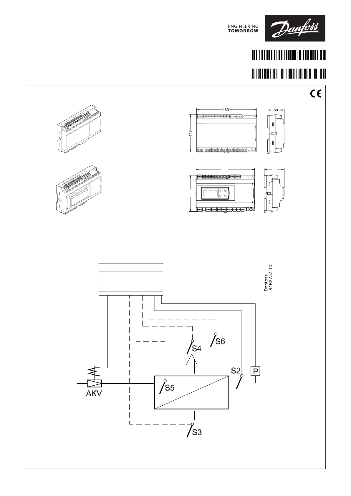
Case/room controller (EEV)
084R8053
Type AK-CC55 Single Coil
Identification
084B4082
084B4083
Principle
AN294432763974en-000501
Dimensions
Danfoss
© Danfoss | Climate Solutions | 2021.12
AN294432763974en-000501 | 1
Page 2
Danfoss
84B3247
84B3248
84B3249
84B8271
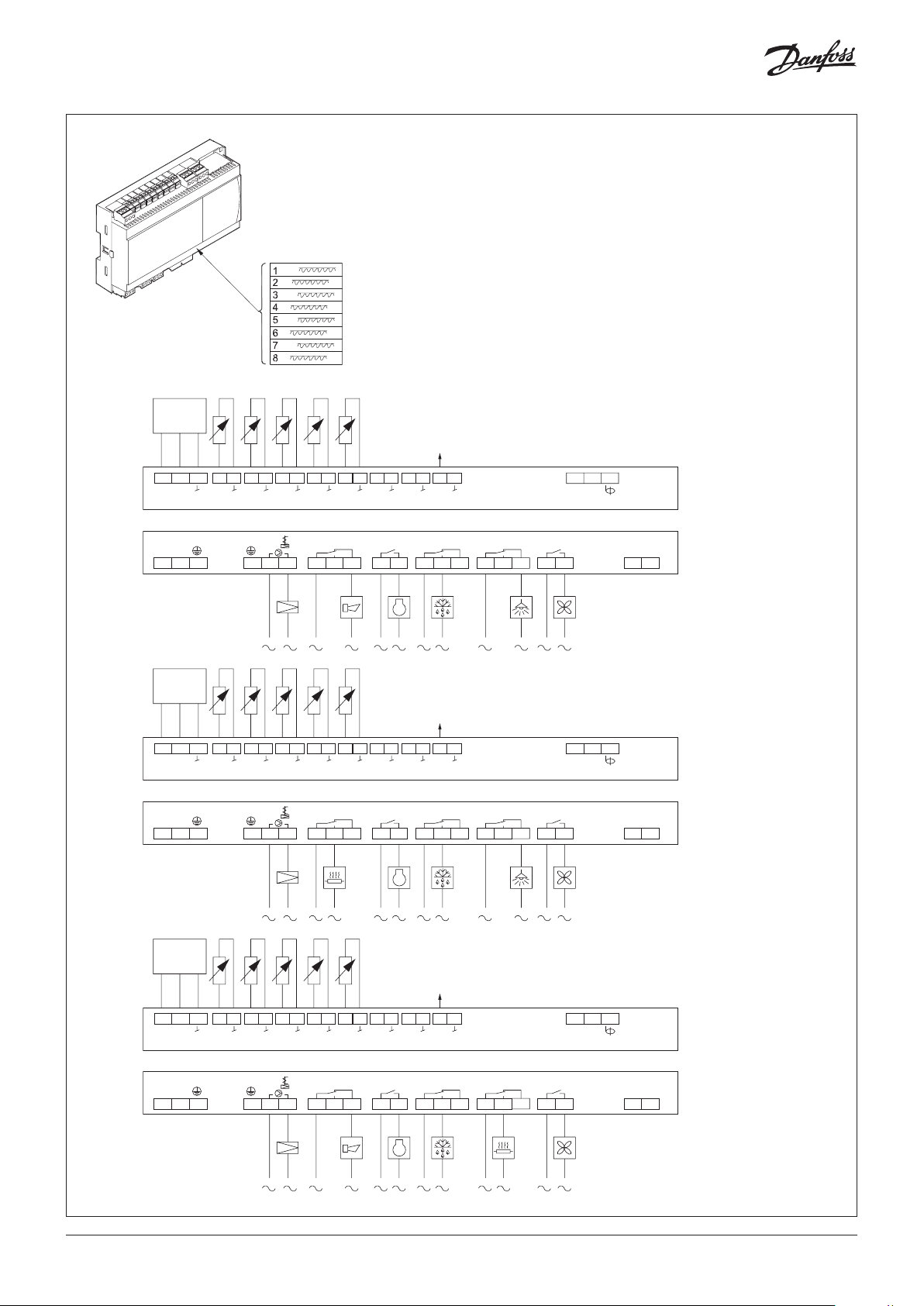
The controller is provided with labels from the factory indicating a generic application.
When selecting the required application, specific labels are provided so that you can
mount the relevant one.
1.
P
132
0 – 10 V/
PWM
40
41 42 43 44 45 46 47 48 49 50 51 52 53 54 60 61 70 71 83 84
s
5V
115 – 230 V AC
LN
1 2 3 7 8 9 10 11 12 13 14 21 22 30 3115 16 17 18 19 20
2.
S2 S3 S4 S5 S6 DI1/
Pe
AKVAlarm Comp.DefrostLight Fan
P
DI2AO1
AI7
B-A
MODBUS
85
+
115 – 230 V AC
1
DI3
Danfoss
132
0 – 10 V/
PWM
40
41 42 43 44 45 46 47 48 49 50 51 52 53 54 60 61 70 71 83 84
s
5V
115 – 230 V AC
LN
1 2 3 7 8 9 10 11 12 13 14 21 22 30 3115 16 17 18 19 20
S2 S3 S4 S5 S6 DI2AO1
Pe
AKVRailheatComp.DefrostLight Fan
DI1/
AI7
B-A
MODBUS
85
+
115 – 230 V AC
2
DI3
3.
P
132
40
41 42 43 44 45 46 47 48 49 50 51 52 53 54 60 61 70 71 83 84
s
5V
115 – 230 V AC
LN
1 2 3 7 8 9 10 11 12 13 14 21 22 30 3115 16 17 18 19 20
S2 S3 S4 S5 S6 DI2AO1
Pe
2 | AN294432763974en-000501
0 – 10 V/
PWM
DI1/
AI7
AKVAlarm Comp.DefrostRailheatFan
B-A
MODBUS
Danfoss
3
85
+
DI3
115 – 230 V AC
Danfoss
© Danfoss | Climate Solutions | 2021.12
Page 3
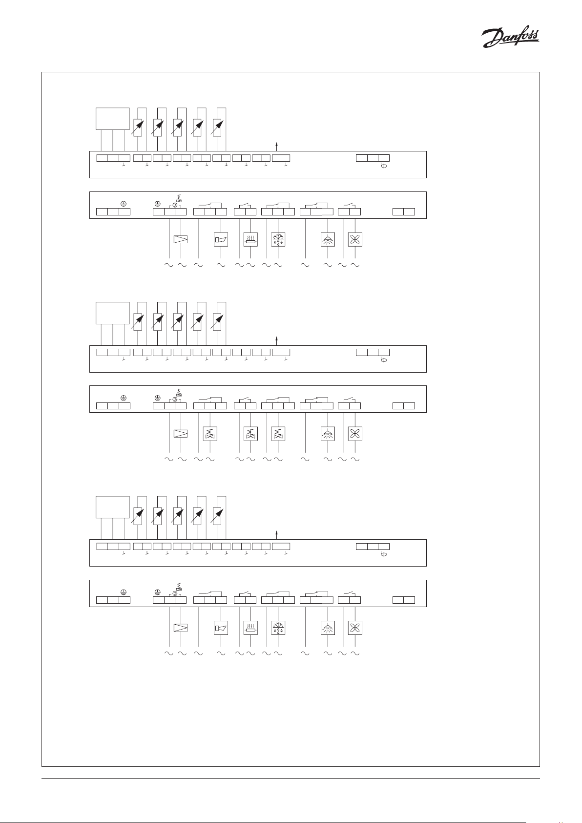
4.
P
132
0 – 10 V/
PWM
40
41 42 43 44 45 46 47 48 49 50 51 52 53 54 60 61 70 71 83 84
s
5V
S2 S3 S4 S5 S6 DI2AO1
Pe
DI1/
AI7
B-A
MODBUS
85
+
4
115 – 230 V AC
LN
1 2 3 7 8 9 10 11 12 13 14 21 22 30 3115 16 17 18 19 20
5.
P
AKVAlarm RailheatDefrostLight Fan
DI3
115 – 230 V AC
Danfoss
84B3250
132
0 – 10 V/
PWM
40
41 42 43 44 45 46 47 48 49 50 51 52 53 54 60 61 70 71 83 84
s
5V
115 – 230 V AC
LN
1 2 3 7 8 9 10 11 12 13 14 21 22 30 3115 16 17 18 19 20
S2 S3 S4 S5 S6 DI2AO1
Pe
AKV Suction Drain HG LightFan
DI1/
AI7
B-A
MODBUS
85
+
115 – 230 V AC
5
DI3
Danfoss
84B3251
6.
P
132
0 – 10 V/
PWM
40
41 42 43 44 45 46 47 48 49 50 51 52 53 54 60 61 70 71 83 84
s
5V
115 – 230 V AC
LN
1 2 3 7 8 9 10 11 12 13 14 21 22 30 3115 16 17 18 19 20
S2 S3 S4 S5 S3B DI2AO1
Pe
AKVAlarm RailheatDefrostLight Fan
DI1/
AI7
B-A
MODBUS
85
+
115 – 230 V AC
6
DI3
Danfoss
84B3252
© Danfoss | Climate Solutions | 2021.12
AN294432763974en-000501 | 3
Page 4

84B3253
U
84B3254
.
84B3266
P
132
0 – 10 V/
PWM
40
41 42 43 44 45 46 47 48 49 50 51 52 53 54 60 61 70 71 83 84
s
5V
S2 S3 S4 S5 S3B S5B DI2AO1
Pe
B-A
MODBUS
85
+
7
115 – 230 V AC
LN
1 2 3 7 8 9 10 11 12 13 14 21 22 30 3115 16 17 18 19 20
8.
P
132
40
41 42 43 44 45 46 47 48 49 50 51 52 53 54 60 61 70 71 83 84
s
5V
Pe
115 – 230 V AC
LN
1 2 3 7 8 9 10 11 12 13 14 21 22 30 3115 16 17 18 19 20
AKVAlarm Defrost BDefrost ALight Fa n
AB
RH
010
S2 S3 S4 S5 S6 DI2AO1
AKVAlarm Humidity DefrostLight Fan
DI1/
AI7
0 – 10 V/
PWM
B-A
MODBUS
85
+
DI3
115 – 230 V AC
DI3
115 – 230 V AC
Danfoss
8
Danfoss
9.
P
132
40
41 42 43 44 45 46 47 48 49 50 51 52 53 54 60 61 70 71 83 84
s
5V
115 – 230 V AC
LN
1 2 3 7 8 9 10 11 12 13 14 21 22 30 3115 16 17 18 19 20
S2 S3 S4 S5 S6 DI2AO1
Pe
4 | AN294432763974en-000501
DI1/
AI7
AKV DO2 DO3 DO4
0 – 10 V/
PWM
Custom set-up
DO5 DO6
B-A
MODBUS
9
85
+
DI3
115 – 230 V AC
Danfoss
© Danfoss | Climate Solutions | 2021.12
Page 5

Data communication Important
AKS 32R
AKV info
It is important that the installation of the data
communication cable is performed correctly
with sufficient distance to high voltage cables.
AKS 32R info
Coordinated defrost via
cable connections
230 V AC (115 AC)
out
Black
Brown
Blue
230 V or 115 V
AC coil
Max. 0.5 A
The signal from one pressure transmitter can be
received by up to 10 controllers.
There must not be a significant pressure drop
from the pressure transmitter's position in the
suction line to the individual evaporators.
Max. 10
The following controllers can be connected in
this way:
EKC 204A, AK-CC 210, AK-CC 250,
AK-CC 450, AK-CC 550 and AK-CC55.
External display
AK-UI55
© Danfoss | Climate Solutions | 2021.12
Danfoss
84B8239
Refrigeration is resumed at the same time when
all controllers have terminated defrost.
Display
084B4075 / 084B4076 / 084B4077
Cable 3 m: 084B4078
Cable 6 m: 084B4079
(L: Max. 100 m)
AN294432763974en-000501 | 5
Page 6

Technical data
Electrical specifications Function data
Electrical data Value
Supply voltage AC [V] 115 V / 230 V, 50/60 Hz
Power consumption [VA] 5 VA
Power ON indicator Green LED
Electrical cable dimensioning [mm] Max. 1.5 mm multi-core cable
Sensor and measuring data
Sensor and measuring data Value
Sensor S2, S6 Pt 1000 AKS11
Sensor S3, S4, S5 Pt 1000 AKS11
PTC 1000 EKS111
NTC5K EKS211
NTC10K EKS221 sensor
(All 3 must be of the same type)
Temperature measuring accuracy Pt1000: -60 – 120 °C. ±0.5 K
PTC1000: -60 – 80 °C. ±0.5 K
NTC5K: -40 – 80 °C. ±1.0 K
NTC10K: -40 – 120 °C. ±1.0 K
Pt1000 sensor specification ±0.3 K at 0 °C
±0.005 K per degree
Pe measuring AKS 32R Ratiometric pressure
transmitter: 10 – 90%
RH measuring 0 – 10 V
Ri > 10K ohm
Accuracy +/- 0,3% FS
Function data Value
Display LED 3 digit
External display, AK-CC55 Single Coil UI 1 external display
External display, AK-CC55 Single Coil 2 external displays
External display connection RJ12
Max. display cable length [m] 100 m
Data communication built-in MODBUS
Data communication option AK-OB55 Lon RS485 module
Clock battery backup power reserve 4 days
Mounting DIN rail
Environmental conditions
Environmental conditions Value
Ambient temperature range, operating [°C] 0 – 55 °C
Ambient temperature range, transport [°C] -40 – 70 °C
Enclosure rating IP IP20
Relative humidity range [%] 20 – 80%, non-condensing
Shocks/Vibrations No shocks and vibrations
(Not AK-CC55 Compact)
allowed
Input and output relay specifications
Input and
output relay
specifications
Digital input DI1
Digital input DI3 115 V / 230 V AC
Solid state
output
Relays DO2
Analogue
output/ PWM
NOTE:
• DO2 to DO6 are 16 A relays.
• Max. load must be observed.
• DO5 / DO6 is recommended for load with high inrush current e.g. EC Fan
and LED light.
• All relays are sealed for use with flammable refrigerant like Propane
R290.
• Compliance with EN 60 335-2-89: 2010 Annex BB.
Input/
output
DI2
DO1 (for
AKV coil)
DO3
DO4
DO5
DO6
AO1 0 / 10 V Pulse Width Modulated
Description
Signal from dry contact functions
Requirements to contacts: Gold plating
Cable length must be max. 15 m
Use auxiliary relays when the cable is longer
Open loop: 12 V (SELV)
Contact 3.5 mA
115V / 230 V AC
Max. 0.5 A
Max. 1 x 20 W AKV for 115 V AC
2 x 20 W AKV for 230 V AC
Note: 2 EC coils are not supported.
115 V / 230 V AC
Load max.: CE. 8 (6)A
UL. 8A res. 3FLA 18LRA
Load min.: 1VA
Inrush: DO5 DO6 TV-5 80A
(PWM) max. 15 mA.
0 – 10 V variable, max. 2 mA
6 | AN294432763974en-000501
© Danfoss | Climate Solutions | 2021.12
Page 7

Electric noise
Cables for sensors, low voltage DI inputs and data communication
must be kept separate from other electric cables:
- Use separate cable trays
- Keep a distance between cables of at least 10 cm
- Long cables at the low voltage DI input should be avoided
Every possible safeguard is incorporated into our products to
prevent this. However, a wrong installation could still present
problems. Electronic controls are no substitute for normal, good
engineering practice.
Danfoss will not be responsible for any goods, or plant
components, damaged as a result of the above defects. It is the
installer's responsibility to check the installation thoroughly, and
Installation considerations
Accidental damage, poor installation, or site conditions, can give
rise to malfunctions of the control system, and ultimately lead to a
plant breakdown.
to fit the necessary safety devices.
Special reference is made to the necessity of signals to the
controller when the compressor is stopped and to the need of
liquid receivers before the compressors.
Your local Danfoss agent will be pleased to assist with further
advice, etc.
Replacing AK-CC 550A with AK-CC55
Be aware when exchanging an AK-CC 550A controller with a new AK-CC55 controller - new wiring principles!
• Pressure sensor has new connection – signal and ground are
switched
• SPDT relays have a new wiring scheme – NO and NC terminals
are switched (e.g. defrost heater on when it should be off)
• Modbus has new connection scheme (A,B and screen)
AK-CC 550A
C NC NO
AK-CC55
C NO NC
• New AK-UI55 displays and cables with 6 wires vs. 4 wires for
EKA 16x
AK-CC55 does not support two EEC coils connected to one AKV output.
Pressure transmitter can be shared between AK-CC 550 and AK-CC55.
DI2 defrost coordination can be wired between AK-CC 550 and AK-CC55.
© Danfoss | Climate Solutions | 2021.12
AN294432763974en-000501 | 7
Page 8

Operation with setting display
Display AK-UI55 Set
The values will be shown with three digits, and with a setting you can determine whether the temperature is to be shown in °C or in °F.
Lights in event of alarm — press on alarm button — alarm relay is reset — alarm code displayed — e.g. “A1”
Alarm codes are shown on page 18.
Lights up in event of:
Energy optimization
Cooling
Defrosting
Fan operation
SET:
Long press (3 seconds) gives access to the “SEt” menu.
If the operation is locked with a password, “PS” is shown. Enter the code.
Shows the setting for a chosen parameter / saves a changed setting.
Short press gives access to entering of the thermostat’s cut-out limit.
The display can give the following messages:
-d- Defrost is in progress
Err The temperature cannot be displayed due to a sensor error
Err1 The display cannot load data from the controller. Disconnect and then reconnect the display
Err2 Lost display communication
ALA The alarm button is activated. The first alarm code is then shown
- - - At top position of the menu or when max. value has been reached, the three dashes are shown in the top of the display
- - - At bottom position of menu or when min. value has been reached, the three dashes are shown in the bottom of the display
Loc The configuration is locked. Unlock by pressing (for 3 seconds) on the ‘up arrow’ and ‘down arrow’ simultaneously
UnL The configuration is unlocked
- - - The parameter has reached min. or max. limit
PS A password is required for access to the menu
Fan Appliance cleaning has been initiated. The fans are running
OFF Appliance cleaning is activated and the appliance can now be cleaned
OFF The main switch is set to Off
SEr The main switch is set to service / manual operation
CO Flashes: Will display in event of a refrigerant leakage alarm, but only if the refrigerant is set up for CO
Long press (3 seconds) gives access to the
information menu “InF”.
Up arrow / Down arrow / Arrow to left:
Navigation in the menu and setting of values.
Long press (3 seconds) will start a defrost,
"-d-" is shown in the display. Ongoing
defrosting can be stopped by a long press.
Factory setting
If you need to return to the factory-set values, do the following:
- Cut off the supply voltage to the controller
- Keep up "∧" and down "∨" arrow buttons depressed at the same time as you reconnect the supply voltage
- When FAc is shown in the display, select "yes".
8 | AN294432763974en-000501
© Danfoss | Climate Solutions | 2021.12
Page 9

Parameter grouping at display operation
84B8272
SET button,
(Return)
Danf
84B8279
(Return)
SET
Set
cFg
<
SET
(PS)
<
r-- o03
A-- r89
c-- r00
d--
n--
F--
t--
h--
o--
p--
q--
u--
<
(Return)
Menu groups
See also the following pages.
3 s: Configuration settings
PS: Password (if any)
Main switch
r12
Application
o61
MODBUS address
Food type
Cut-out temperature
Ther. sensor S4 %
r15
Ther. sensor S4% night
r61
Alarm sensor S4%
A36
Display air S4%
o17
o30
Refrigerant type
o20
Min. transmitter range
o21
Max. transmitter range
d01
Defrost method
d03
Defrost interval
d10
Defrost sensor
d04
Max. defrost time
d02
Defrost stop temperature
<
<
Inf
StA SET
App SET
in SET
out SET
buS SET do2
SoFSET do3
< do4
Output status
When you want info on a relay
output, the dot will show
whether the relay is activated
(energized) for, e.g.:
do4 = not activated
do.4 = activated
*)
The output's function.
(Determined at configuration).
The DOs and AOs can also be forced controlled from this menu, when r12
Main switch has been set in position "service".
Forced control of a function can also be performed in codes q11 to q27.
Danfoss
**)
The input's function.
(Determined at configuration).
Info button,
3 s: Information for service use
See control state message
See selected application
MODBUS quality
See SW version
(Return)
di1/
AI7
do1 Akv di2 **
do5
do6
Ao1
*
*
*
*
*
*
di3 **
AI1 PE
AI2 S2
AI3 S3
AI4 S4
Read output status
AI5 S5
AI6 **
<
(Return)
**
Read input status
oss
Get a good start
With the following procedure you can start regulation very quickly:
1. Open parameter r12 and stop the regulation (in a new and
not previously set unit, r12 will already be set to 0 which
means stopped regulation)
2. Select application based on the wiring diagrams on pages 2-4
3. Open parameter o61 and set the application number
4. For network. Set the address in o03
5. Then select a set of presets from the "Food type" help table
6. Open parameter r89 and set the number for the array of
presettings. The few selected settings will now be transferred
to the menu
7. Set the desired cut-out temperature r00
8. Set the weighted thermostat air temperature between S4 and
S3 sensor r15
9. Set the weighted thermostat air temperature between S4 and
S3 during night operation r61
10. Set the weighted alarm air temperature between S4 and S3
A36
11. Set the weighted display readout between S4 and S3 o17
12. Select refrigerant via parameter o30
13. Set the pressure transmitter min. and max. range via
parameter o20 and o21
14. Set the desired defrost method in d01
15. Set the interval time between defrost starts in d03
16. Set the desired defrost sensor in d10
17. Set the maximum defrost time in d04
18. Set the defrost stop temperature in d02
19. Open parameter r12 and start the regulation
20. Go through the parameter list and change the factory values
where needed.
21. Get the controller up and running on network:
• MODBUS: Activate scan function in system unit
• If another data communication card is used in the controller:
- Lon RS485: Activate the function o04
- Ethernet: Use the MAC address
Food type
Setting of presettings (r89). After
setting 1-5,
setting is returned to 0.
Food type =
Temperature (r00) 8 °C 0 °C -2 °C -20 °C -24 °C
Max. temp. setting (r02) 10 °C 4 °C 2 °C -16 °C -20 °C
Min. temp. setting (r03) 4 °C -4 °C -6 °C -24 °C -28 °C
Upper alarm limit (A13) 14 °C 8 °C 8 °C -15 °C -15 °C
Lower alarm limit (A14) 0 °C -5 °C -5 °C -30 °C -30 °C
Upper alarm limit for S6 (A22) 14 °C 8 °C 8 °C -15 °C -15 °C
Lower alarm limit for S6 (A23) 0 °C -5 °C -5 °C -30 °C -30 °C
1
Vegetables2Milk
3
Meat/
fish
4
Frozen
food
5
Ice
cream
© Danfoss | Climate Solutions | 2021.12
AN294432763974en-000501 | 9
Page 10

Fault message
In an error situation the alarm LED on the front will be on and the alarm relay will be activated (depending on priority).
If you push the alarm button for 3 seconds you can see the alarm report in the display. (Alarm priorities can be changed. See the User Guide.)
Here are the messages that may appear:
Alarm text
Code
Hardware failure
E01
Clock lost time
E06
Pe Evap. pressure A - Sensor error
E20
S2 Gas outlet A - Sensor error
E24
S3 Air ON evap. A - Sensor error
E25
S4 Air OFF evap. A - Sensor error
E26
S5 Evaporator A - Sensor error
E27
S6 product temp. A - Sensor error
E28
S3 Air ON evap. B - Sensor error
E34
S5 Evaporator B - Sensor error
E37
Humidity sensor - Sensor error
E59
High temperature alarm A
A01
Low temperature alarm A
A02
Door open alarm
A04
Max defrost hold time exceeded
A05
Refrigerant not selected
A11
S6 high product temperature A
A13
S6 low product temperature A
A14
DI alarm 1
A15
DI alarm 2
A16
Main switch set OFF
A45
Case in cleaning mode
A59
High temperature alarm B
A70
Low temperature alarm B
A71
CO2 leak detected
AA2
Refrigerant leak detected
AA3
High humidity alarm
a02
Low humidity alarm
a03
Wrong IO configuration
a04
Evaporator is icing up
X02
Flash gas detected
X03
Max defrost time exceeded A
Z01
Fan alarm
A34
Valve driver alarm
A43
Data communication: The importance of individual alarms can be defined with a setting. The setting must be carried out in the group "Alarm destinations"
Description
The controller has a hardware failure
Clock has lost valid time
Sensor signal is out of range. Please check the sensor for correct operation
Sensor signal is out of range. Please check the sensor for correct operation
Sensor signal is out of range. Please check the sensor for correct operation
Sensor signal is out of range. Please check the sensor for correct operation
Sensor signal is out of range. Please check the sensor for correct operation
Sensor signal is out of range. Please check the sensor for correct operation
Sensor signal is out of range. Please check the sensor for correct operation
Sensor signal is out of range. Please check the sensor for correct operation
Sensor signal is out of range. Please check the sensor for correct operation
The alarm temperature has been above the max alarm limit for a longer time period than the set alarm delay.
The alarm temperature has been below the min alarm limit for a longer time period than the set alarm delay.
The door has been open for a too long time
The controller has been waiting longer time than permitted after a co-ordinated defrost.
The refrigerant has not been selected hence control can not be initiated
The S6 Product temperature has been above the max alarm limit for a longer time period than the set alarm delay.
The S6 Product temperature has been below the min alarm limit for a longer time period than the set alarm delay.
Alarm signal from digital input signal
Alarm signal from digital input signal
The controller manin switch has been set to either Stop or Manaual control. Alternatively a digital input set up for
"main switch" function, has stopped control
A case cleaning operation has been started on a case
The alarm temperature has been above the max alarm limit for a longer time period than the set alarm delay.
The alarm temperature has been below the min alarm limit for a longer time period than the set alarm delay.
CO2 is leaking from the refrigerantion system
Refrigerant is leaking from the refrigeration system
The humidity level is too high
The humidity level is too low
Inputs and outputs have not been configured correctly
The adaptive defrost function has detected heavy ice formation on evaporator.
The adaptive defrost function has detected heavy flash gas in front of injection valve
The last defrost cycle has stopped on time instead of set temperature
Alarm from digital input monitoring function
Alarm from digital input monitoring function
Additional information not relevant for safe installation and use can be found on Danfoss Store:
For more detailed information, please see the respective User Guide.
10 | AN294432763974en-000501
© Danfoss | Climate Solutions | 2021.12
 Loading...