

Page 1
User Guide
Case/room controller (EEV)
Type AK-CC55 Single Coil and
AK-CC55 Single Coil UI
SW Ver. 1.7x
For refrigeration appliances and cold storage rooms.
Page 2

AK-CC55 Single Coil and AK-CC55 Single Coil UI
Contents
Introduction 6
Portfolio overview 7
Function overview 7
Connectivity 8
Data communication 8
AK-CC55 Single Coil and Single Coil UI 9
External display 9
Controller functionality 10
Functions 10
Injection control 10
Adaptive superheat control 10
Adaptive liquid control 11
Liquid injection by use of stepper valve 11
Oil recovery 11
Adaptive liquid control (option 1 and 2) 12
Fixed opening degree (option 3 and 4) 12
Safety 12
Temperature control 12
Food temperature sensor 13
Temperature monitoring 13
Thermostat bands 13
Night setback of thermostat value 13
Temperature sensor types 14
Appliance cleaning 15
Appliance shutdown 15
Defrost control 16
Electrical defrosting 16
Hot gas defrosting 16
Natural defrost 16
Start of defrost 17
Stop of defrost 17
Defrost sequence 17
Real-time clock 19
Coordinated defrost 19
© Danfoss | Climate Solutions | 2022.03 BC364229688105en-000201 | 2
Page 3

AK-CC55 Single Coil and AK-CC55 Single Coil UI
Adaptive defrosting 19
4 dierent adaptive defrost modes 19
Melt function 20
Control of two compressors (only with custom set-up) 20
Rail heat 21
Fan 22
Light function 23
Night blind 24
Humidity control 24
Heating function (only with custom set-up) 26
Digital inputs 26
Forced closing 27
Door contact 27
Display 27
Override 28
Applications 29
AK-CC55 connections and application options 30
Application set-ups and IO connections 31
Product identication 34
AK-CC55 Single Coil connections 35
Data communication 35
AKV info 35
External solid state relay for rail heat 35
AKS 32R info 36
Coordinated defrost via cable connections 36
External display AK-UI55 36
Connections 37
Replacing AK-CC 550 with AK-CC55 38
Operation 40
Operation via data communication 40
Direct operation 40
Operation via AK-UI55 Set 40
Parameter groups when operating via display 42
Get a good start 42
AK-UI55 display menu (SW ver. 1.7x) 44
Thermostat 44
© Danfoss | Climate Solutions | 2022.03 BC364229688105en-000201 | 3
Page 4

AK-CC55 Single Coil and AK-CC55 Single Coil UI
Alarm settings 44
Compressor 45
Defrost 45
Injection control 46
Fan control 46
Defrost schedule 46
Humidity control 47
Miscellaneous 47
Control 49
DO cong and manual 50
Service 51
Operation via AK-UI55 Bluetooth 53
AK-CC55 connect menu (SW ver. 1.7x) 54
Start / Stop 54
Conguration 54
Thermostat control 56
Alarm limits and delays 57
Humidity control 59
Injection control 59
Defrost control 60
Defrost schedules 62
Compressor 63
Fan control 63
Railheat control 64
Light/Blinds/Cleaning control 64
Display control 65
Alarm relay priorities 66
Miscellaneous 66
Advanced 67
Fault message 69
Operating status 71
Product specication 72
Technical data 72
Electrical specications 72
Sensor and measuring data 72
Input and output relay specications 72
© Danfoss | Climate Solutions | 2022.03 BC364229688105en-000201 | 4
Page 5

AK-CC55 Single Coil and AK-CC55 Single Coil UI
Function data 73
Environmental conditions 73
Dimensions 73
Ordering 74
Certicates, declarations, and approvals 75
Statements for the AK-UI55 Bluetooth display 75
Online support 77
© Danfoss | Climate Solutions | 2022.03 BC364229688105en-000201 | 5
Page 6
AK-CC55 Single Coil and AK-CC55 Single Coil UI
Introduction
Application
Complete refrigeration appliance control with great exibility to adapt to refrigeration appliances and cold storage
rooms.
Advantages:
• Universal controller for several dierent refrigeration appliances
• Quick set-up with predened settings
• Easy conguration and service using a mobile app with Bluetooth
• Energy optimization of the whole refrigeration appliance
• Adaptive Minimum Stable Superheat (MSS) control is performed with lowest possible superheat
• Allows the suction pressure to be raised several degrees
• Adaptive Liquid Control (ALC) can be performed with superheat down to 0 degrees on transcritical CO2 systems
with liquid ejectors
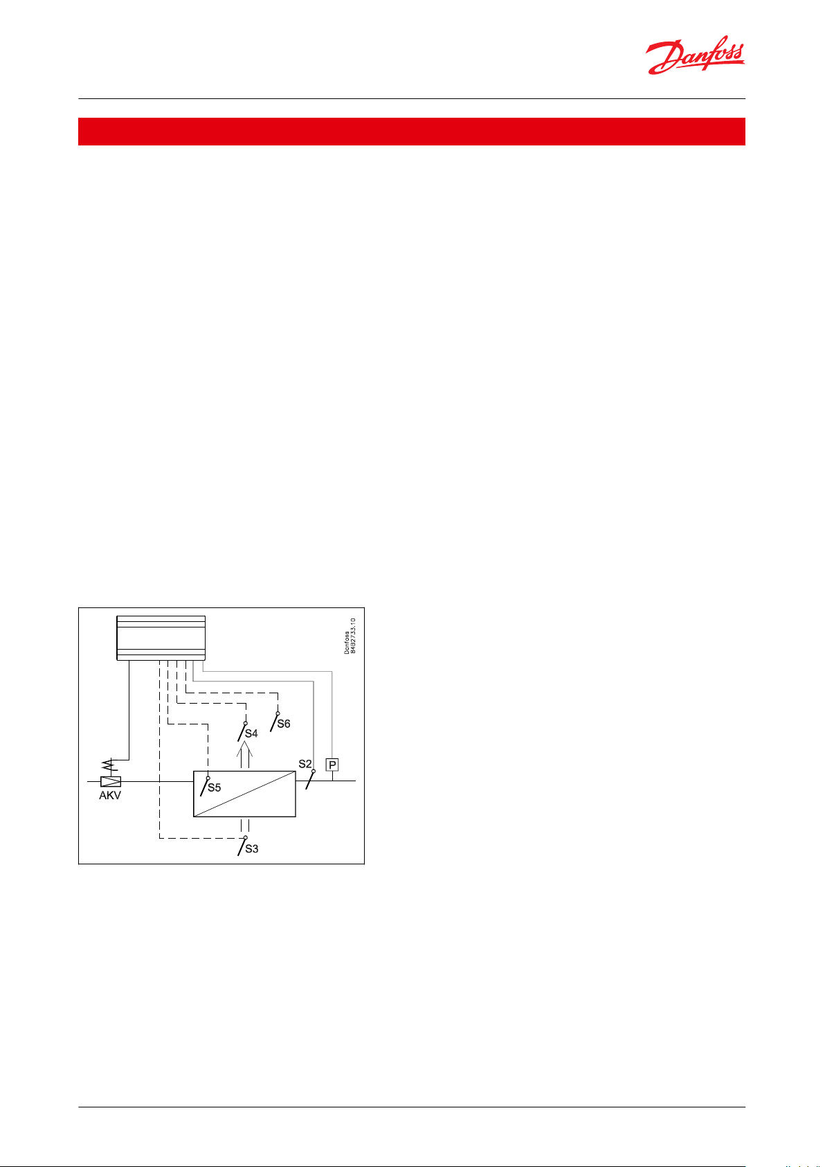
Principle
The temperature in the appliance is registered by one or two temperature sensors which are located in the air ow
before the evaporator (S3) or after the evaporator (S4) respectively. A setting for thermostat, alarm thermostat and
display reading determines the inuence the two sensor values should have for each individual function.
In addition, product sensor S6, which can be optionally placed in the appliance, can be used for registration and
alarming of the temperature near the food items.
The temperature of the evaporator is registered with the S5 sensor which can be used as a defrosting sensor.
In addition to the output of the electronic AKV injection valve, the controller has relay outputs which are dened by
the application setting.
Figure 1: AK-CC55 with evaporator, AKV valve and sensor positions
© Danfoss | Climate Solutions | 2022.03 BC364229688105en-000201 | 6
Page 7
AK-CC55 Compact
AK-CC55 Single Coil
AK-CC55 Single Coil UI
AK-CC55 Multi Coil
Product image
Valve
1 x TXV or AKV
1 x AKV
1 x AKV
3 x AKV
Digital Output3554
Digital input
1 (2)
3 (2)
3 (2)
3 (2)
Analogue Output1111
Analogue Input
5 (4)
6 (7)
6 (7)
6 (7)
Display
1 remote
2 remote
1 remote + 1 Integrated
2 remote
Comm. module
Modbus
Modbus
Modbus
Modbus
Optional comm. module
LON module
LON module
LON module
Application
AK-CC55 Compact
AK-CC55 Single Coil
AK-CC55 Single Coil UI
AK-CC55 Multi Coil
AKV - application (electrically operated expansion valve)
xxx
0 – 10 V to control external stepper driver
x
TXV - application (thermostatic expansion valve + solenoid valve or compressor)
x
Remote hot gas - application
x
One valve, one evaporator, one refrigeration section
xxx
One valve, one evaporator, two refrigeration sections
x
One valve and two evaporators, two refrigeration sections
x
Two valves and two evaporators (same refrigeration section)
x
Three valves and three evaporators (same refrigeration section)
x
Custom conguration of relay outputs
x
x
Two compressorsxx
Heating functionxx
Control of air humidity
x
x
Adaptive superheat
xxx
Adaptive liquid control
(zero superheat control for transcritical CO2 systems with liquid ejectors)
xxx
Adaptive defrosting
x
Product sensor
x
Oil recovery
x
RS485 Lon, option (AK-OB55)
x
x
AK-CC55 Single Coil and AK-CC55 Single Coil UI
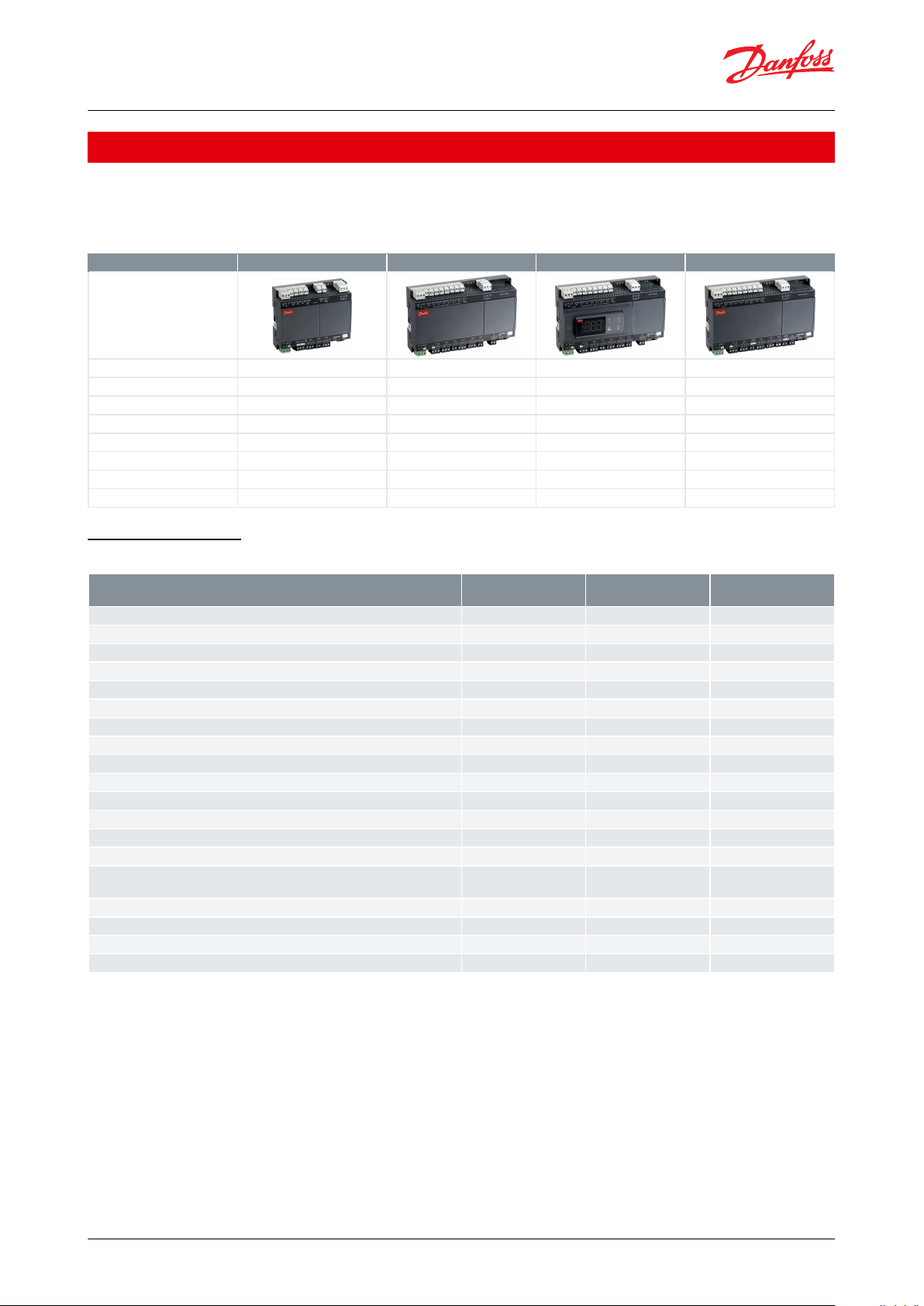
Portfolio overview
The AK-CC55 portfolio contains four controllers with dierent functionalities and application settings, as outlined in
the table.
Table 1: AK-CC55 Portfolio
Function overview
Table 2: AK-CC55 function overview by type
© Danfoss | Climate Solutions | 2022.03 BC364229688105en-000201 | 7
Page 8
Remote Display Service App
AKA 245: LON units
only and max 250
controller parameters
System Manager
Display Bus
Modbus
Modbus
LON/ TCP/IP (SNMP)
Modbus
LON/ TCP/IP (SNMP)
Bluetooth
AK-UI55 Bluetooth
AK-UI55 Set
AK-UI55 Info
Smart Device
(iOS or Android)
AK-CC55 Connect
AK-CC55 Single Coil UI
AK-CC55 Multi Coil
AK-CC55 Compact
KoolProg
Case Controller
Danfoss
80G8333
AK-CC55 Single Coil and AK-CC55 Single Coil UI
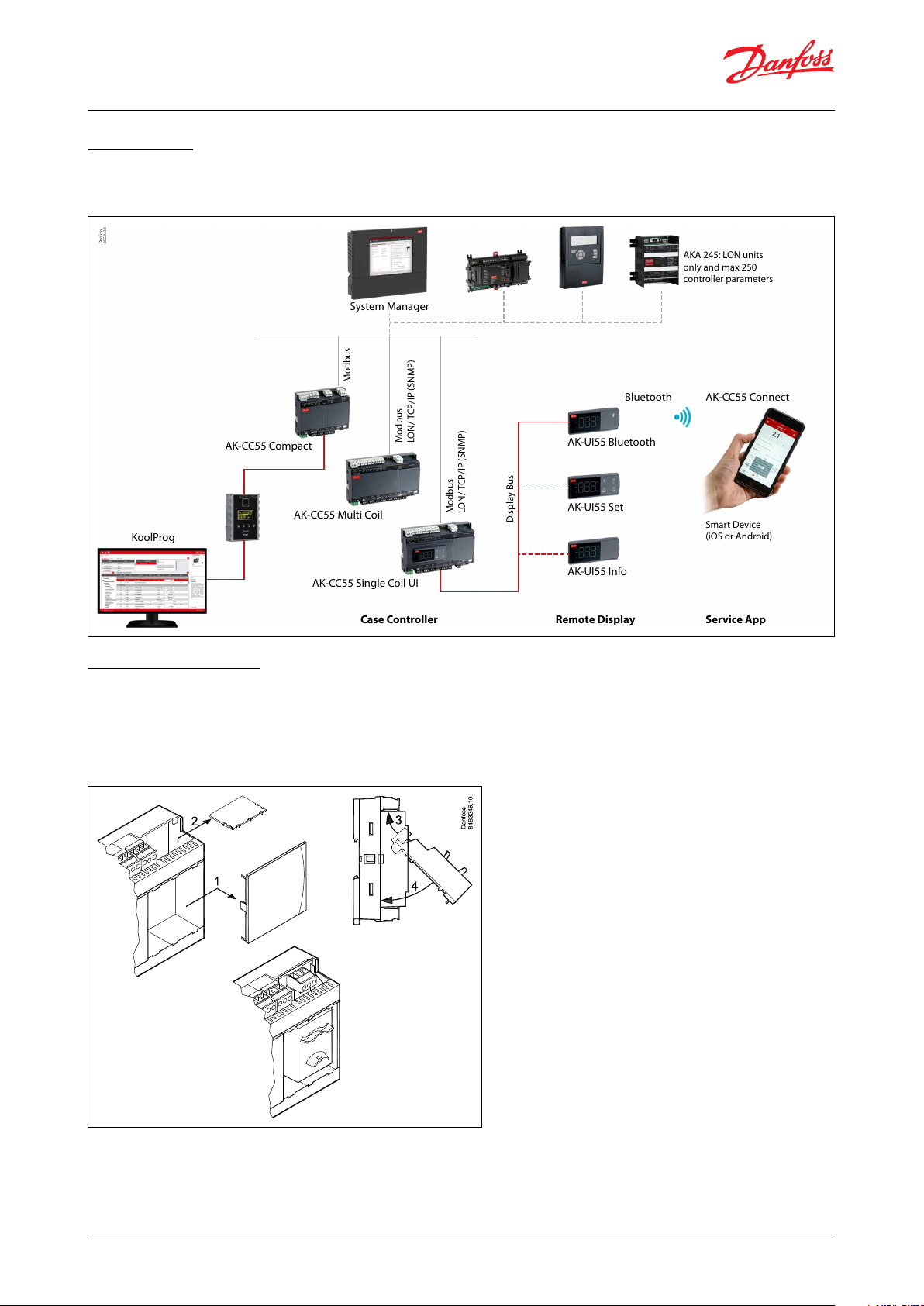
Connectivity
The diagram outlines the connectivity options presented by AK-CC55 for the design of system functionality.
Figure 2: Connectivity
Data communication
The controller has built-in MODBUS data communication. If there is a requirement for a dierent form of data
communication, a Lon RS 485 module can be inserted in the controller.
The connection must then be to the module.
Figure 3: Mounting of communication module
© Danfoss | Climate Solutions | 2022.03 BC364229688105en-000201 | 8
Page 9
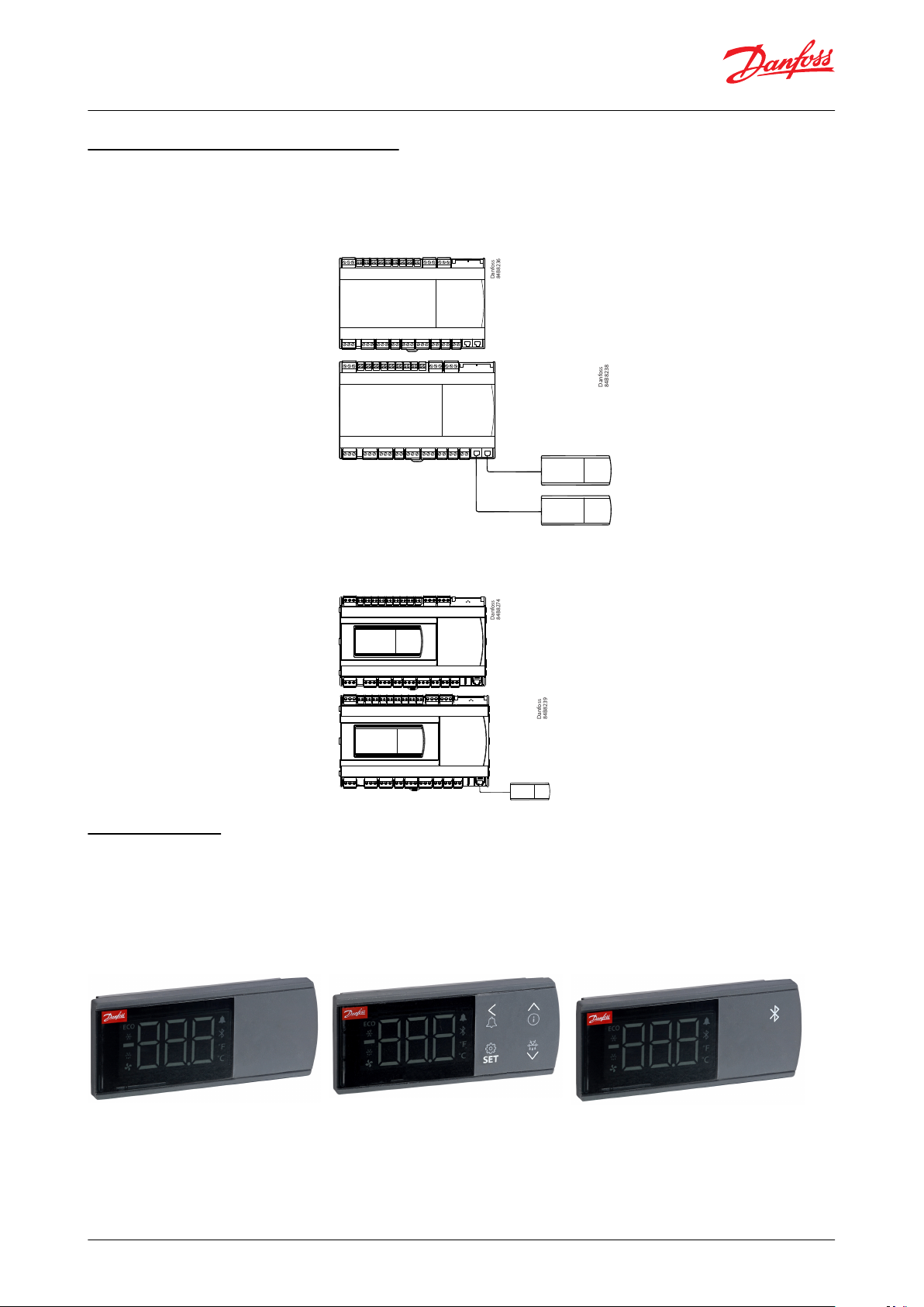
Standard enclosure. Typically used for display cases
where the controller is mounted in a tray.
Danfoss
84B8236
The standard enclosure can be expanded with one or
two external displays.
Danfoss
84B8238
Enclosure with built-in setting display. Typically used
for cold rooms.
Danfoss
84B8274
For controllers with built-in, only one external display
can be connected.
Danfoss
84B8239
AK-CC55 Single Coil and AK-CC55 Single Coil UI
AK-CC55 Single Coil and Single Coil UI
AK-CC55 Single Coil – Controlling one EEV valve.
An application mode setting will congure inputs and outputs for the desired use. There are nine applications to
choose from. Regulation is performed using an AKV expansion valve or an external stepper driver via Analogue
Output A01.
AK-CC55 Single Coil UI
Single Coil controller with built-in display. Same functionalities as AK-CC55 Single Coil.
External display
There are three versions available with dierent functions:
• AK-UI55 Info: Temperature display.
• AK-UI55 Set: Temperature display with control buttons on the front.
• AK-UI55 Bluetooth: Temperature display with Bluetooth communication, for use with AK-CC55 Connect Mobile
app.
Figure 4: AK-UI55 Info Figure 5: AK-UI55 Set Figure 6: AK-UI55 Bluetooth
© Danfoss | Climate Solutions | 2022.03 BC364229688105en-000201 | 9
Page 10
Danfoss
84B2732
S2
AKV
p
e
AK-CC55 Single Coil and AK-CC55 Single Coil UI
Controller functionality
Functions
• Day/night thermostat with ON/OFF or modulating principle
• Product sensor S6 with separate alarm limits
• Switch between thermostat settings via digital input
• Adaptive control of superheat
• Adaptive liquid control
• Oil recovery (ushing oil back to condensing unit)
• Adaptive defrosting based on diagnostics
• Start of defrost via schedule, digital input, network or setting display
• Natural, electric or hot gas defrost
• Stop of defrost on time and/or temperature
• Coordination of defrosting among several controllers in a line-up
• Pulsing or ECO control of fans when thermostat is satised
• Appliance cleaning function for documentation of HACCP procedure
• Rail heat control via day/night load or dewpoint
• Humidity control in cold storage rooms
• Door function
• Control of two compressors
• Control of night blinds
• Light control
• Heat thermostat
• High accuracy inputs will guarantee a better measuring accuracy than stated in the standard EN ISO 23953-2
without subsequent calibration (Pt 1000 ohm sensor)
• Support of user-dened temp. sensor type
• Integrated MODBUS communication with the option of mounting a LonWorks communication card
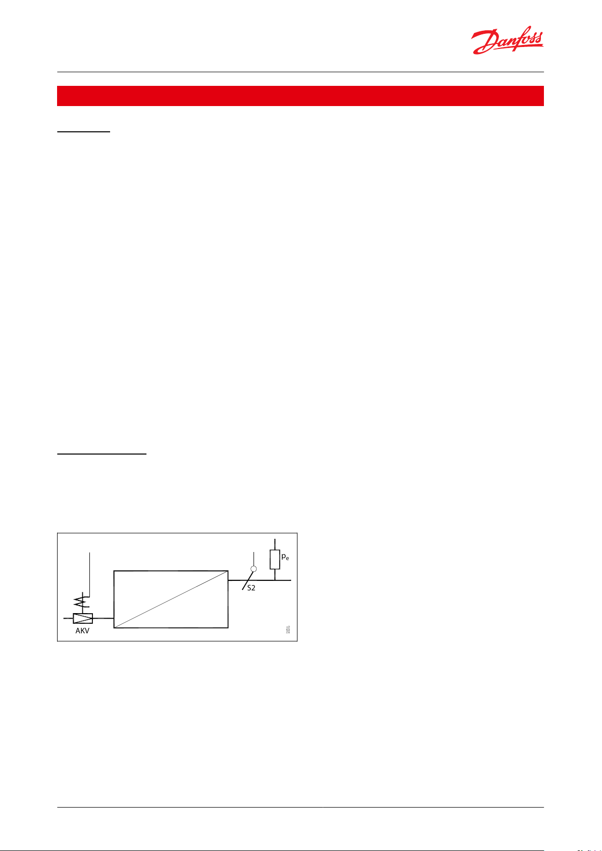
Injection control
Adaptive superheat control
Liquid injection in the evaporator is controlled by an electronic injection valve of the type AKV. The valve operates
as both expansion valve and solenoid valve. The controller opens and closes the valve based on sensor readings.
Figure 7: Adaptive superheat control with AKV valve
The superheat is measured via a pressure sensor Pe and temperature sensor S2. By using a pressure sensor, and
temperature sensor a correct measurement of superheat is achieved under all conditions which ensures a very
robust and precise control. The signal from one pressure transmitter can be shared by max. 10 controllers, but only if
there is no signicant pressure dierence between the evaporators in question.
The function contains an adaptive algorithm which independently adjusts the valve’s opening so that the
evaporator constantly supplies optimum amount of refrigerant.
© Danfoss | Climate Solutions | 2022.03 BC364229688105en-000201 | 10
Page 11
S2
P
EKF
0 – 10 V
ETSLLSV
M
Danfoss
84Z8230
AK-CC55 Single Coil and AK-CC55 Single Coil UI
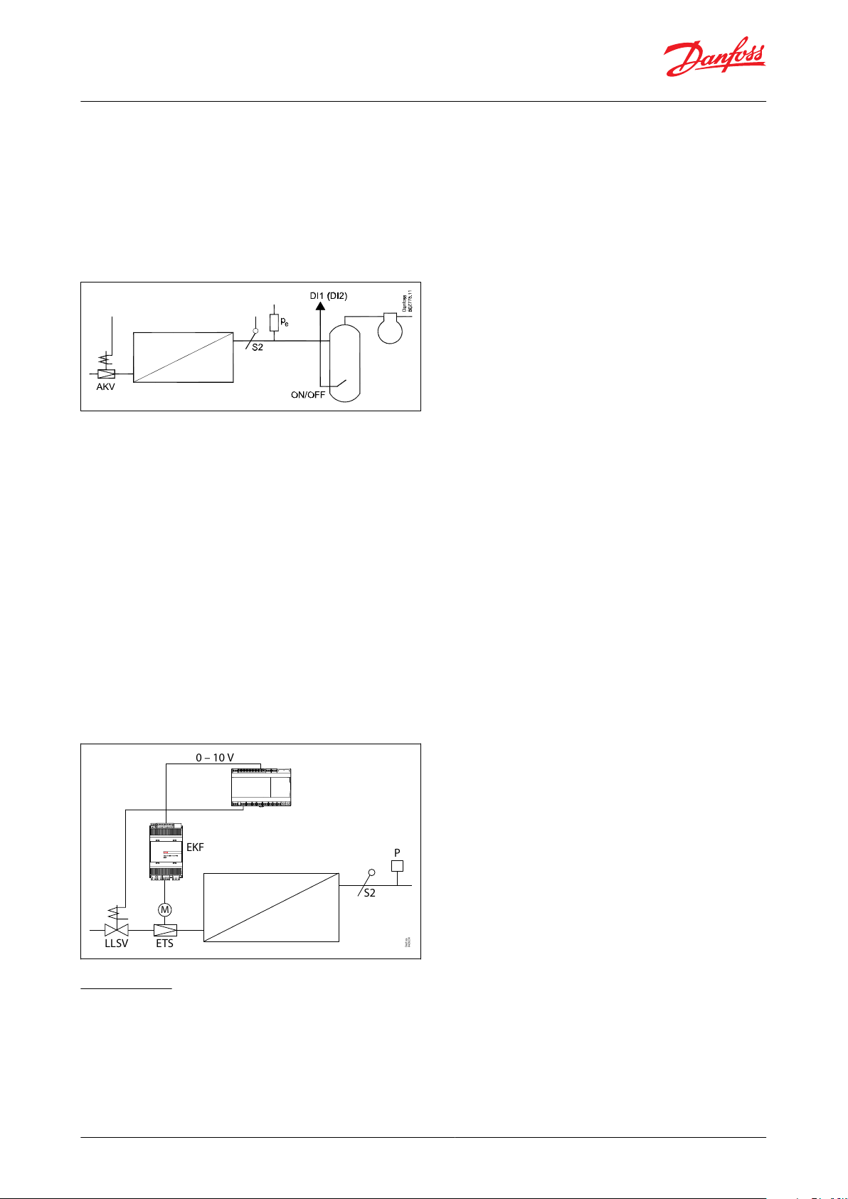
Adaptive liquid control
Adaptive liquid control is used in trans-critical CO2 ejector systems, which allow liquid ow. When adaptive liquid
control is initiated, the superheat of the evaporator will be minimized so that a controlled amount of liquid is
present at the outlet of the evaporator.
This type of control requires that the controller receives an on/o signal from (for example) a suction accumulator in
the suction line.
Figure 8: Adaptive liquid control with AKV valve
A level switch in the tank will register when the liquid level exceeds the max. level. When this happens, the
controller will switch to dry expansion, and then back to liquid control when the liquid level has dropped. The
function is dened in setting o02, o37 or o84.
The function can also be activated via data communication from a system unit. If the adaptive liquid control signal is
lost, the controller will automatically switch back to dry expansion.
WARNING:
Accidental actuation may allow liquid throughput to the compressor. It is the installer’s responsibility to ensure that
signal loss to the controller will not result in liquid throughput to the compressor. Danfoss accepts no responsibility
for damage resulting from inadequate installation.
Liquid injection by use of stepper valve
Instead of AKV, an external stepper driver can be connected to AO1 (0 – 10 V) to drive a stepper valve. DO1 (AKV
output) is then congured to close a liquid line solenoid valve (LLSV) when the stepper valve output is 0%. The LLSV
is also closed at power failure.
Figure 9: Injection control via step motor valve and liquid
line solenoid valve (LLSV)
Oil recovery
In some multi evaporator systems, oil might accumulate in the evaporators over time. The oil recovery feature will
help to get the oil back to the compressors/suction accumulator.
Oil recovery can be initiated via a digital input signal or as a network signal. When oil recovery is initiated, the valve
opening degree will be increased to ush the oil out of the evaporator.
© Danfoss | Climate Solutions | 2022.03 BC364229688105en-000201 | 11
Page 12
y
x
D
E
A
B
C
Danfoss
84B8328
xyABCDE
Time
Temp%
AKV OD%
Superheat
SH ref
Adaptive liquid control forced cooling
Oil recovery
AK-CC55 Single Coil and AK-CC55 Single Coil UI
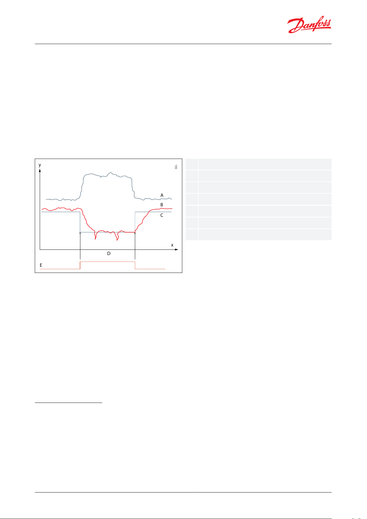
Oil recovery has the following control options:
0 = No oil recovery
1 = Adaptive liquid control + Normal fan control
2 = Adaptive liquid control + Fan OFF
3 = Fixed opening degree of valve + Normal fan control
4 = Fixed opening degree of valve + Fan OFF
Adaptive liquid control (option 1 and 2)
When oil recovery is initiated, the injection function will switch to adaptive liquid control, decreasing the superheat
reference, increasing the valve opening degree and thereby achieving a controlled amount of liquid refrigerant at
the outlet of the evaporator. As the compressor controller at the same time runs with a higher capacity/speed, this
combination will result in a higher amount of returned oil.
Figure 10: Adaptive liquid control increases valve opening degree during oil return
Fixed opening degree (option 3 and 4)
When oil recovery is initiated, the injection function will switch to a user-dened opening degree to ood the
evaporator with refrigerant and thereby ush the oil back to the compressor/suction accumulator. However, this
option provides no control or monitoring of the superheat and it is solely up to the user to ensure that the system
design provides a safeguard of the compressors.
Safety
A couple of safety functions are in place to protect the preserved food from too low temperatures during an oil
recovery cycle.
If an oil recovery has been ongoing for a longer period than the set “Max. oil recovery time”, oil recovery will be
stopped, and normal control resumed.
Oil recovery is stopped if the alarm air temperature decreases below the set low alarm limit.
Temperature control
The temperature in the appliance is registered by one or two temperature sensors which are located in the return air
before the evaporator (S3) or after the evaporator (S4) respectively. A setting for the thermostat, night thermostat,
alarm thermostat and display reading determines how much the two sensor values should inuence each individual
function, e.g. 50% of S4 will produce an equal value from both sensors.
The actual temperature control can take place in two ways:
1.
As an ordinary ON/OFF regulation with a dierential, or
2.
As a modulating control where the temperature variation will not be nearly as high as in ON/OFF control
© Danfoss | Climate Solutions | 2022.03 BC364229688105en-000201 | 12
Page 13
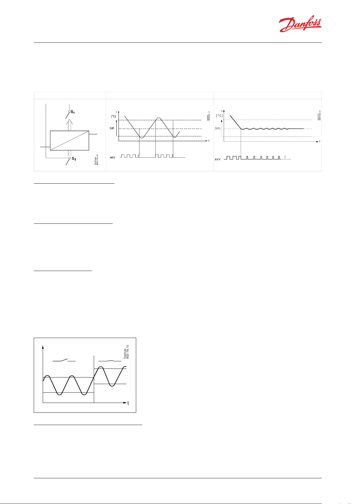
ON/OFF control
Modulating control
AK-CC55 Single Coil and AK-CC55 Single Coil UI
There is, however, a limit to the use of a modulating control as it can only be used in remote cabinets. It is not
recommended to use modulating thermostat control in low temperature applications. In applications with one
evaporator and one compressor the thermostat function with ON/OFF control should be selected. In remote
cabinets, the thermostat function may either be selected for ON/OFF control or modulating control.
Table 3: Control methods
Food temperature sensor
A separate optional product sensor S6, which may be placed in the appliance, can also be used and can register and
monitor the food temperature in the appliance. There are separate alarm limits and time delays for the product
sensor.
Temperature monitoring
Just as is possible for the thermostat, the alarm monitoring can be set with a weighting between S3 and S4 so that
you can decide how much the two sensor values should inuence the alarm monitoring. Minimum and maximum
limits can be set for alarm temperature and time delays. A longer time delay can be set for high temperature alarm.
This time delay is active for pull-down after defrosting, appliance cleaning and start-up.
Thermostat bands
Thermostat bands can be used benecially for appliances where dierent product types are stored, which requires
dierent temperature conditions. It is possible to change between the two dierent thermostat bands via a contact
signal on a digital input. Separate thermostat and alarm limits can be set for each thermostat band – also for the
product sensor.
For the defrost control, separate defrost stop temperature and max. defrost time can be set for each thermostat
band. For the compressor control it is possible to disable the second compressor in thermostat band 2 if required.
Figure 11: Thermostat band function with two dierent band settings
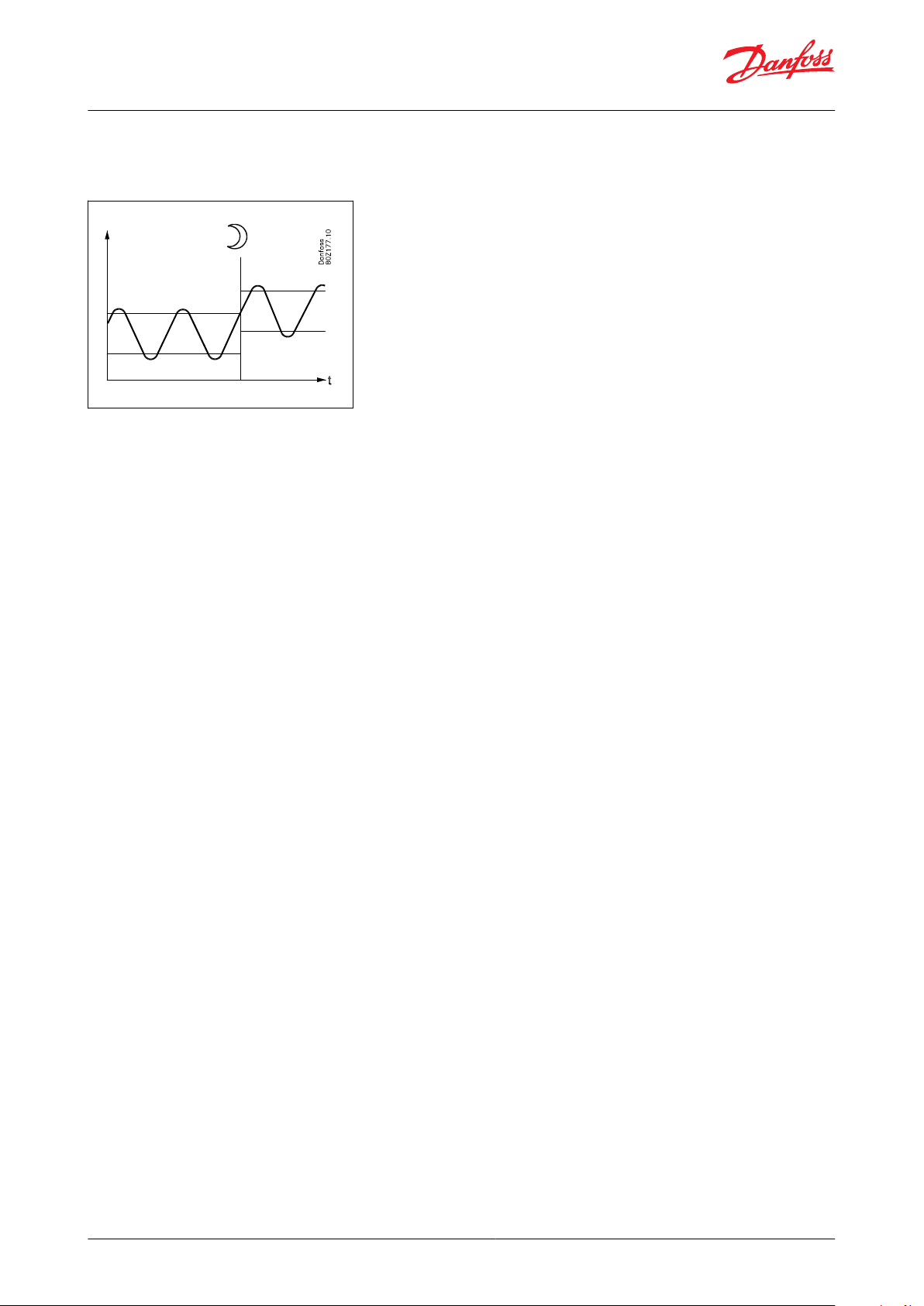
Night setback of thermostat value
In refrigeration appliances there may be big load dierences between the shop’s opening and closing hours,
especially if night lids/blinds are used. The thermostat reference may be raised here without it having any eect on
the product temperature.
Change-over between day and night operation can take place as follows:
© Danfoss | Climate Solutions | 2022.03 BC364229688105en-000201 | 13
Page 14
AK-CC55 Single Coil and AK-CC55 Single Coil UI
• via an external switch connected to a digital input
• via a signal from the data communication system
Figure 12: Thermostat band function with Night setback
Temperature sensor types
The S2 and S6 sensors always have to be Pt1000 sensors due to the high measuring accuracy.
For the S3, S4 and S5 sensors, the user can select between the following sensor types:
0=Pt1000 (Danfoss AKS 11)
1=PTC1000 (Danfoss EKS 111)
2=NTC 5k (Danfoss EKS 211)
3=NTC 10k (Danfoss EKS 221)
4 = User-dened
If “User-dened” is selected, three sensor measuring points must be provided and based on these three sensor
points, a sensor characteristic is generated.
A sensor point is dened by setting a temperature value and the corresponding resistance value at this temperature.
The resistance value is set via two values for kohm and ohm respectively. These values can be found in the data
sheet for the sensor.
The three sensor points must be:
1.
Lowest temperature in wanted measuring range
2.
Highest temperature value in wanted temperature range
3.
Temp. value in the middle where a high measuring accuracy is required
A sensor error is detected at temperature values below/above the min./max. temperature values typed in for the
sensor points.
© Danfoss | Climate Solutions | 2022.03 BC364229688105en-000201 | 14
Page 15

y
x
A
350
300
250
200
150
100
50
0
-40 -20 0 20 40 60 80
Danfoss
80G8338
xyA
Temp [°C]
R [kohm]
Sensor point (-30 °C, 180 kΩ)
-++°C1÷+
Fan2÷÷O3++°C
AK-CC55 Single Coil and AK-CC55 Single Coil UI
Figure 13: Example of sensor points from a NTC sensor
Limitations:
A user dened temperature sensor can only be be dened within the temperature range from -40 – +60 °C and
within the resistance range from 400 – 179.999 ohm.
When applying a new user dened sensor type, please contact Danfoss for validation of compliance and measuring
accuracy.
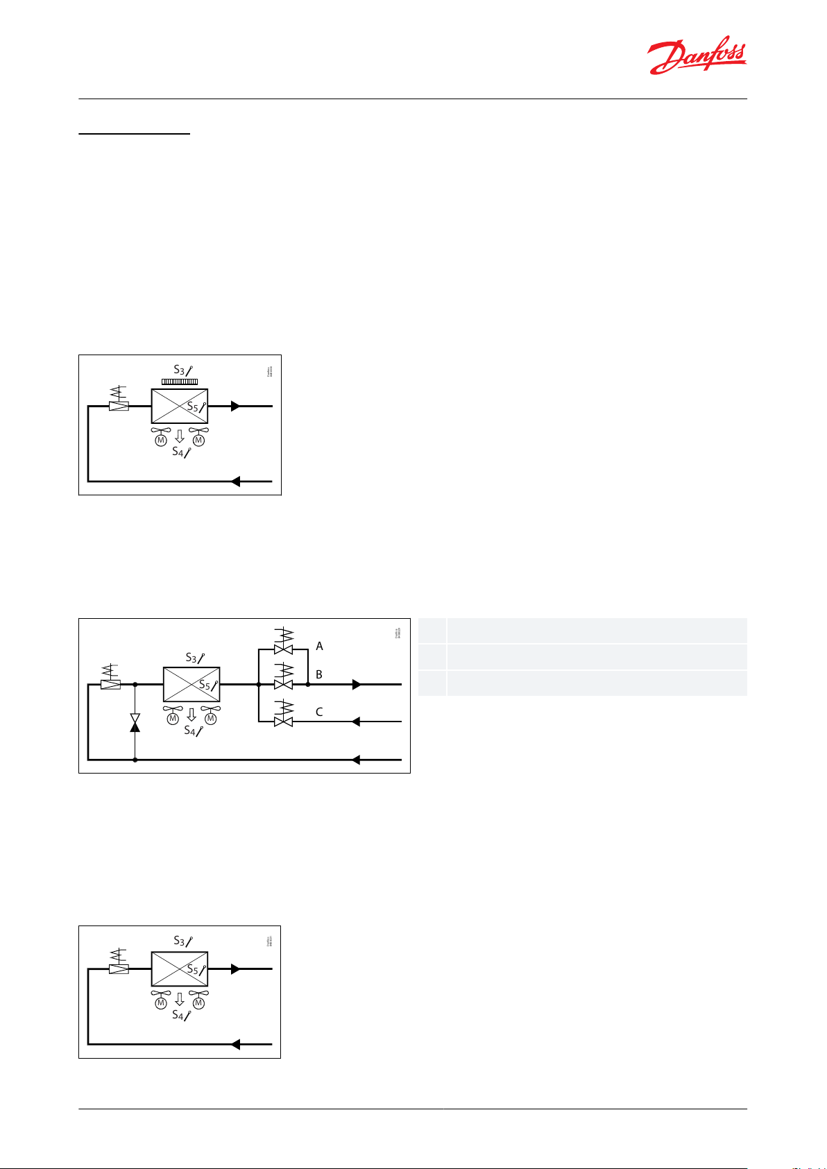
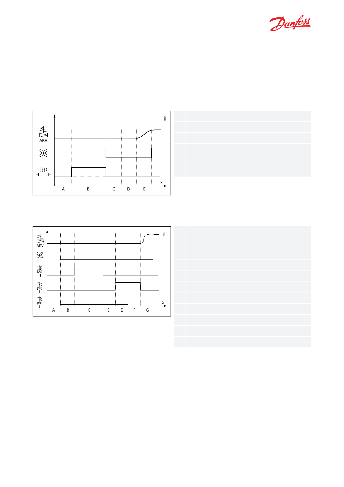
Appliance cleaning
This function makes it easy for the shop’s sta to carry out a cleaning of the appliance according to a standard
procedure. Appliance cleaning is activated via a pulse signal – as a rule via a key switch placed on the appliance or
via the AK-CC55 Connect mobile app.
Appliance cleaning is carried out via three phases:
1.
At the rst activation, the refrigeration is stopped, but the fans keep on operating in order to defrost the
evaporators. ”Fan” is shown on the display.
2.
At the second activation, the fans are also stopped and the appliance can now be cleaned. ”OFF” is shown on the
display.
3.
At the third activation, refrigeration is recommenced. The display will show the actual appliance temperature,
o97 setting.
When appliance cleaning is activated, a cleaning alarm is transmitted to the normal alarm recipient. A later
processing of these alarms will document that the appliance has been cleaned as often as planned.
There are no temperature alarms during appliance cleaning.
Table 4: Appliance cleaning function
Appliance shutdown
The function closes the AKV valve and all outputs are switched o. The cooling appliance is stopped like the “Main
switch”, but this happens without an “A45 standby alarm”. The function can be enabled by a switch on the DI input
or via a setting through data communication.
© Danfoss | Climate Solutions | 2022.03 BC364229688105en-000201 | 15
Page 16
A
B
C
Danfoss
84B8329
S
3
S
4
S
5
M M
ABC
Bypass valve
Suction valve
Hot gas valve
Danfoss
84B8330
S
3
S
4
S
5
M M
Danfoss
84B8331
S
3
S
4
S
5
M M
AK-CC55 Single Coil and AK-CC55 Single Coil UI
Defrost control
Defrost method
The following defrost methods can be selected:
0: None
1: Electrical
2: Hot gas defrost (Simple)
3: Natural
Electrical defrosting
At electrical defrost, an electrical heater is placed in front of the evaporator and the fan will “pull” the hot air through
the evaporator during defrosting.
Figure 14: Electrical defrosting
Hot gas defrosting
Remote hot gas defrost is supported in application mode 5. The hot gas defrost sequence covers control of the hot
gas valve, suction valve and drain valve. It is intended for smaller systems in e.g. supermarkets – the functional
content has not been adapted to industrial systems with large refrigerant charges.
Figure 15: Hot gas defrosting
Simple hot gas defrosting
If hot gas defrost is selected in application 1-3, the compressor will be running during defrost and a hot gas valve
(HGV) is bypassing the compressor discharge gas to the evaporator inlet and thereby the evaporator is defrosted.
Natural defrost
At natural defrost, the ice is melted by running the fans and thereby circulating warm air through the evaporator.
Figure 16: Natural defrost
© Danfoss | Climate Solutions | 2022.03 BC364229688105en-000201 | 16
Page 17
AK-CC55 Single Coil and AK-CC55 Single Coil UI
Start of defrost
A defrost can be started in dierent ways:
Interval:
Defrost is started at xed time intervals like e.g. every eighth hour. An interval must ALWAYS be set to a "higher"
value than the period set between two defrostings when a schedule or network signal is used.
Week schedule:
Here defrost can be started at xed times of the day and night. However, max. 6 defrosts per day.
Contact:
Defrost is started with a contact signal on a digital input.
Figure 17: Defrost start
Network:
The defrost start signal is received from a system manager via data communication.
Adaptive defrost:
Here defrosting is started based on intelligent registering of evaporator performance.
Max. thermostat runtime:
When the aggregate time has passed a preset value, a defrost will be initiated.
Manual:
An extra defrost can be activated from the defrost button on the AK-UI55 Set display (though, not with application
5) or via a parameter setting. All the mentioned methods can be used in parallel – if just one of them is activated, a
defrost will be started.
Stop of defrost
Defrosting can be stopped by either:
• Time
• S4A temperature (with time as safety)
• S5A temperature (with time as safety)
• S5A and S5B temperatures (with time as safety)
When the selected defrost stop sensor reaches the set defrost stop limit, the defrost is terminated. If the defrost stop
sensor does not reach the set defrost stop limit within the set max. defrost time, the defrost will be terminated on
time.
Minimum defrost time
When using hot gas for defrosting, the heat is coming from within the evaporator, and this means that the S5 sensor
is rising fast when the inner layer of ice is melted. This will sometimes cause parts of the evaporator not to be
defrosted when defrost is terminated on S5 evaporator temperature.
To prevent this, the user is given the option of setting a minimum defrost time. When a defrost is initiated, it will
have to run for the set minimum time even if the set defrost stop limit has been reached by the selected defrost stop
sensor.
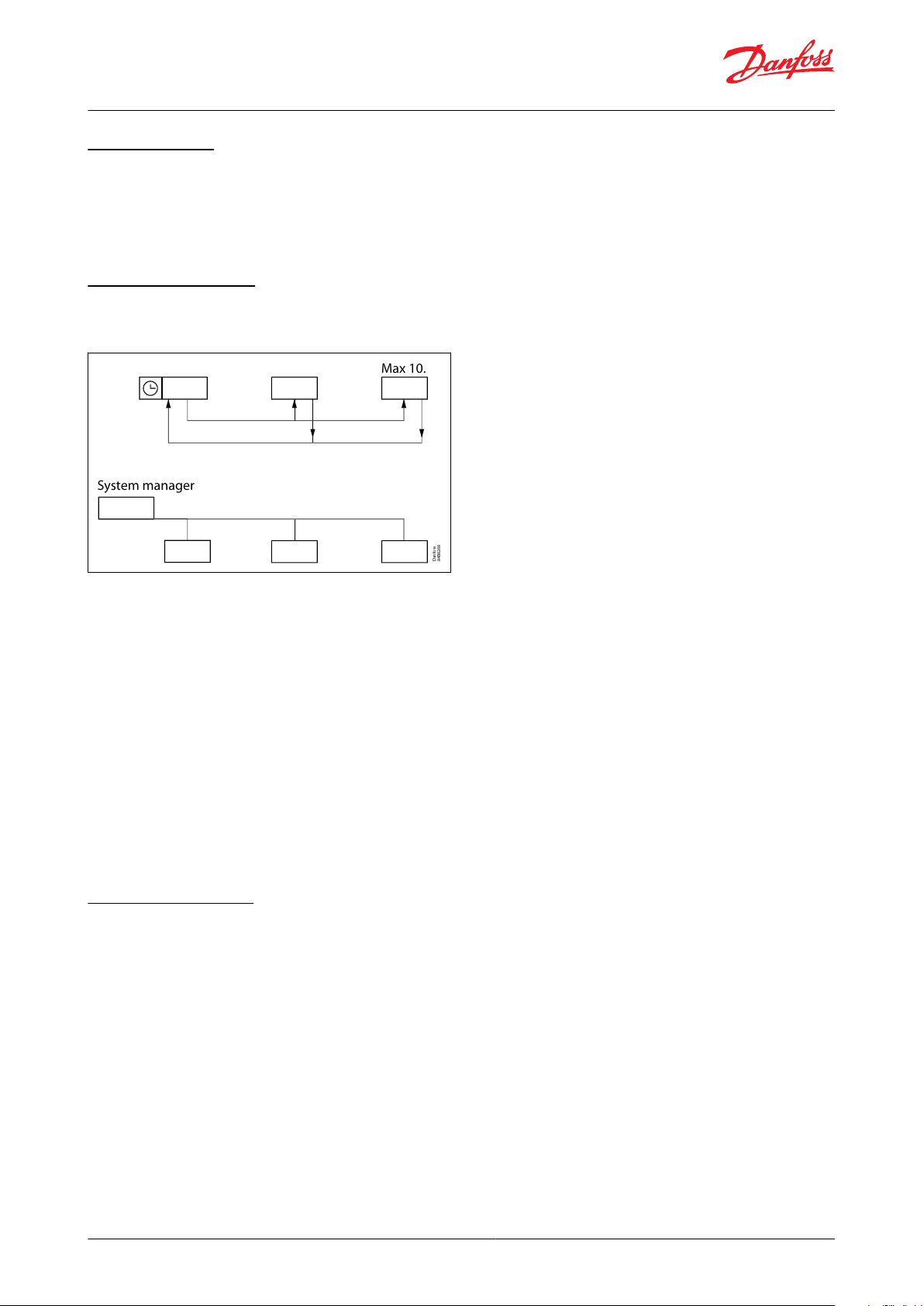
Defrost sequence
When a defrost is initiated, the controller will run through the following sequence:
© Danfoss | Climate Solutions | 2022.03 BC364229688105en-000201 | 17
Page 18
BA C D E
Danfoss
84B8332
X
AKV
xABCDETime
Pump down
Defrost
Hold
Drip
Fan delay
Danfoss
84B8333
A B C D E F G
x
H
I
J
AKV
xABCDEFGHIJ
Time
Pump down
Hot gas injection delay
Defrost
Hold
Drain
Drip
Fan delay
Hot gas valve
Drain
Suction
AK-CC55 Single Coil and AK-CC55 Single Coil UI
1.
Pump down: where the evaporator is emptied of refrigerant
2.
Hot gas inj. delay (Hot gas only): where suction valve is given time for closing
3.
Defrost: where the ice on the evaporator is melted
4.
Hold after defrosting: where multiple controllers wait for each other (coordinated defrost)
5.
Drip o: where remaining water is dripping o evaporator
6.
Drain delay (Hot gas only): where the drain valve is opened to drain the liquid refrigerant
7.
Fan delay: where the fans are restarted when the remaining water on the evaporator has turned into ice
Figure 18: Electrical defrost sequence
During an electrical defrost sequence where the defrost heater is ON during defrost, AKV valve is closed and fans are
running during defrost but stopped during drip.
Figure 19: Remote hot gas defrost sequence
Remote hot gas defrost sequence where suction valve and drain valves are closed while hot gas valve is injecting
hot gas into the evaporator. After defrost, the drain valve is opening to drain the evaporator for liquid refrigerant
and then the suction valve is opening. When the water has dripped o the evaporator, liquid injection is started via
the AKV valve and the fans start when the evaporator temperature has reached the fans' start temperature.
Fan control during defrost
During the defrost sequence, the evaporator fans can be controlled in one of the following ways:
1.
The fan is OFF in the entire defrost sequence
2.
The fan is ON during the entire defrost sequence except during fan delay state
3.
The fan is ON during defrost state and is OFF in the rest of the defrost sequence
4.
Like option 2, however the fans can be stopped if the selected defrost stop sensor exceeds a set fan stop limit
© Danfoss | Climate Solutions | 2022.03 BC364229688105en-000201 | 18
Page 19
System manager
Max 10.
Danfoss
84B8268
AK-CC55 Single Coil and AK-CC55 Single Coil UI
Real-time clock
The controller has a built-in real-time clock which can be used to start defrosts. This clock has a power reserve of
four days.
If the controller is equipped with data communication, the clock will automatically be updated from a Danfoss
system manager.
Coordinated defrost
There are two ways in which coordinated defrost can be arranged.
Figure 20: Coordinated defrost options
Either with wire connections between the controllers or via data communication:
Wire connections
The digital input DI2 must be congured for coordinated defrost and wiring must be connected between the
relevant controllers. When one controller starts a defrost, all the other controllers will follow suit and likewise start a
defrost. After the defrost, the individual controllers will move into waiting position. When all are in waiting position
there will be a change-over to refrigeration.
Coordination via data communication
Here the system manager handles the coordination.
The controllers are gathered in defrosting groups and the system manager ensures that defrosting is started in the
group according to a weekly schedule.
When a controller has completed defrosting, it sends a message to the system manager and then goes into a
waiting position. When every controller in the group is in a waiting position, refrigeration is again permitted in all
the individual controllers.
Adaptive defrosting
The Danfoss adaptive defrost algorithm detects the amount of ice build-up and cancels a scheduled defrost if it is
not needed, or it can be set up to only perform defrost if the evaporator air ow is getting interrupted by frost or ice.
The overall concept is based on comparison of the energy uptake on the refrigerant ow side with the energy
emission on the air ow side. When the evaporator is clean, an energy balance is assumed, while a growing
imbalance can be identied when ice formation is build up on the evaporator surface ending up with blocked
airow.
4 dierent adaptive defrost modes
0 O
1. Monitoring
Can be set up in parallel to other defrost methods and generate an alarm in case of blocked air ow / ice-up of the
evaporator. If ash gas issues are detected on the refrigerant ow side, a ash gas alarm is generated.
© Danfoss | Climate Solutions | 2022.03 BC364229688105en-000201 | 19
Page 20

AK-CC55 Single Coil and AK-CC55 Single Coil UI
2. Adaptive skip day:
Allows the controller to cancel (skip) defrosts scheduled within day time. Defrosts scheduled at night operation will
be carried through and not skipped. Only defrosts that are set up via a schedule in the frontend using master
control functions or set up via the internal defrost schedule in the controller can be skipped.
3. Adaptive skip day and night:
With this set-up, the controller can allow to cancel (skip) defrosts scheduled both within day time and within night
time. For both adaptive skip day and night max. 3 consecutive defrosts can be skipped, whereafter the 4th
scheduled defrost will be performed even if only little ice should be present.
4. Full adaptive:
Full Adaptive mode is ideal for applications where defrost is not requested to be performed at a certain time, but
can be performed whenever ice is starting to interrupt the airow. It makes sense to combine this mode with the
defrost interval timer as a safety timer.
Adaptive defrosting requires the following connections:
• Expansion valve type AKV
• Pe evaporator pressure and S2 gas out temperature
• Temperature signal from both S3 and S4. Sensors must be placed in the airow/channel immediately before / after
the evaporator.
• Condensing temperature Tc is distributed via the network from the system manager. If Tc is not received by the
case controller, the adaptive defrost function is using default back-up values.
NOTE:
Adaptive parameters will be reset after a defrost has been initiated or at main switch in stopped or service mode. At
start up with a warm evaporator (measured with S2 sensor), the evaporator is presumed clean. If the evaporator
temperature is measured below 0.1 °C, adaptive defrost will request a defrost start to secure a clean evaporator.
Min. time between defrosts
There is a preset 2 hours minimum time between defrosts. This avoids that planned defrosts in accordance with the
weekly schedule are carried out immediately after an adaptive defrost has been carried out. The time applies from
when an adaptive defrost has been completed to when a planned defrost is again permitted. The adaptive defrost
will not start defrosting with a shorter interval than the 2 hours either.
Melt function
This function will prevent the air ow in the evaporator from being reduced by frost created by uninterrupted
operation for a long time.
The function is activated if the thermostat temperature has remained in the range between -5 °C and +10 °C for a
longer period than the set melting interval. The refrigeration will then be stopped during the set melting period.
The frost will be melted so that the air ow and hence the evaporator’s capacity will be greatly improved.
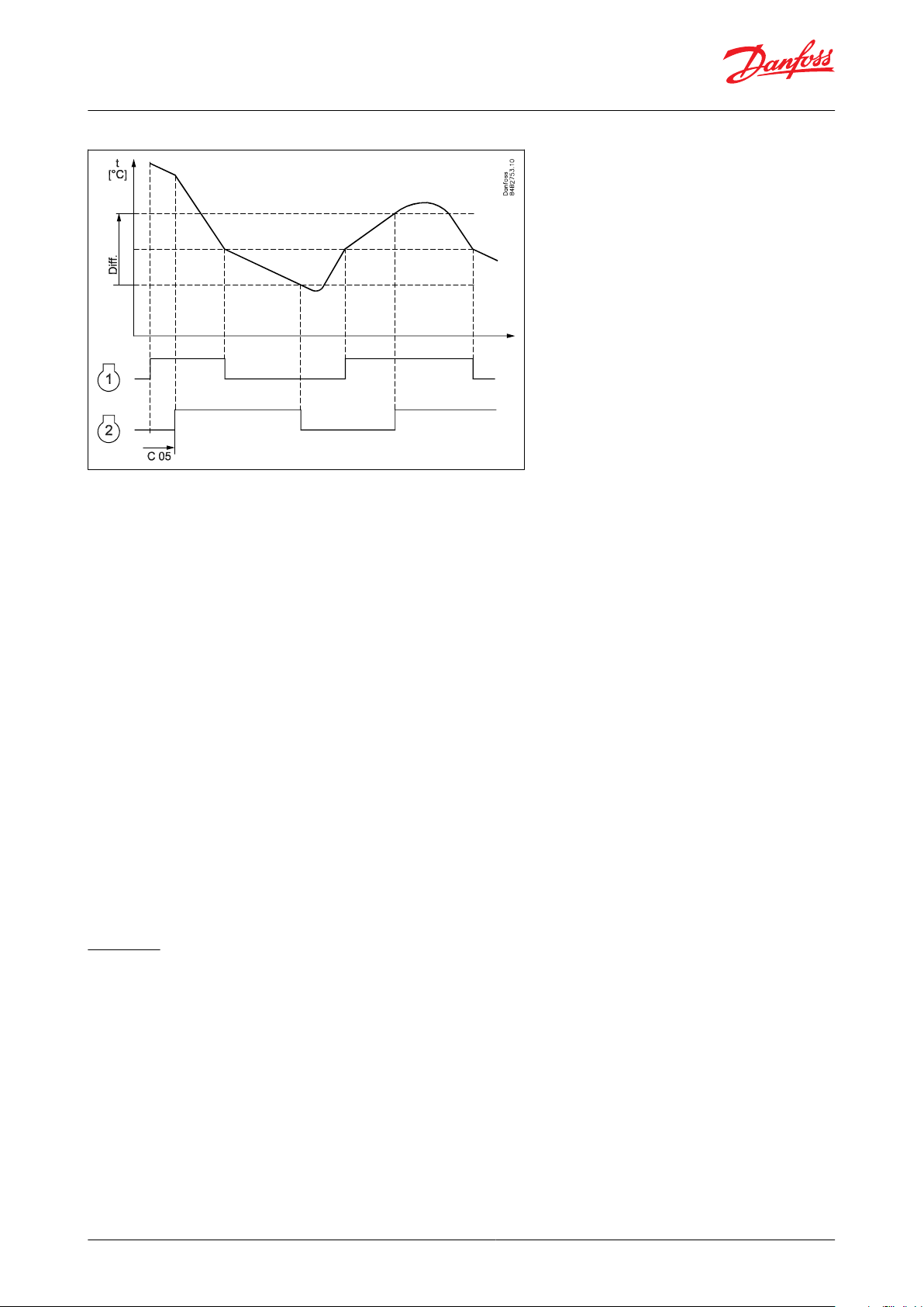
Control of two compressors (only with custom set-up)
Two compressor steps can be controlled cyclic or sequentially. At cyclic control, two compressors must be of the
same size, while in sequential control compressor step 1 can be larger than step 2.
© Danfoss | Climate Solutions | 2022.03 BC364229688105en-000201 | 20
Page 21
AK-CC55 Single Coil and AK-CC55 Single Coil UI
Figure 21: Control of two compressors
Cyclic control
When the controller demands refrigeration, it will rst cut in the compressor with the shortest operating time. After
the time delay, the second compressor will be cut in.
When the temperature has dropped to ”the middle of the dierential”, the compressor with the longest operation
time will be cut out.
The running compressor will continue until the temperature has reached the cut-out value. Then it will cut out.
When the temperature again reaches the middle of the dierential, a compressor will again be started.
If one compressor cannot maintain the temperature within the dierential, the second compressor will also be
started.
If one of the compressors has run on its own for two hours, the compressors will be changed over so that
operational time is balanced.
The two compressors must be of a type that can start up against a high pressure.
The compressor's settings for ”Min. On time” and ”Min. O time” will always have top priority during normal
regulation. But if one of the override functions is activated, like e.g. defrost, door open function, case shutdown,
forced closing, the ”Min. On time” will be disregarded.
Sequential control
Compressor steps are controlled in the same manner as described for cyclic control, but compressor step 1 will
always be started rst and cut out as the last one. No time equalization is available in sequential control mode.
Rail heat
It is possible to pulse-control the power to the rail heat in order to save energy. Pulse control can either be
controlled according to day/night load or dew point.
Relay or analogue output
A relay output can be used when long cycle times are permitted. If fast pulsing is required, the AO1/PWM output
can be used. The output must be connected to an external power solid state relay. The cycle time must be
congured for the relay output in o43 or for analogue output in P82.
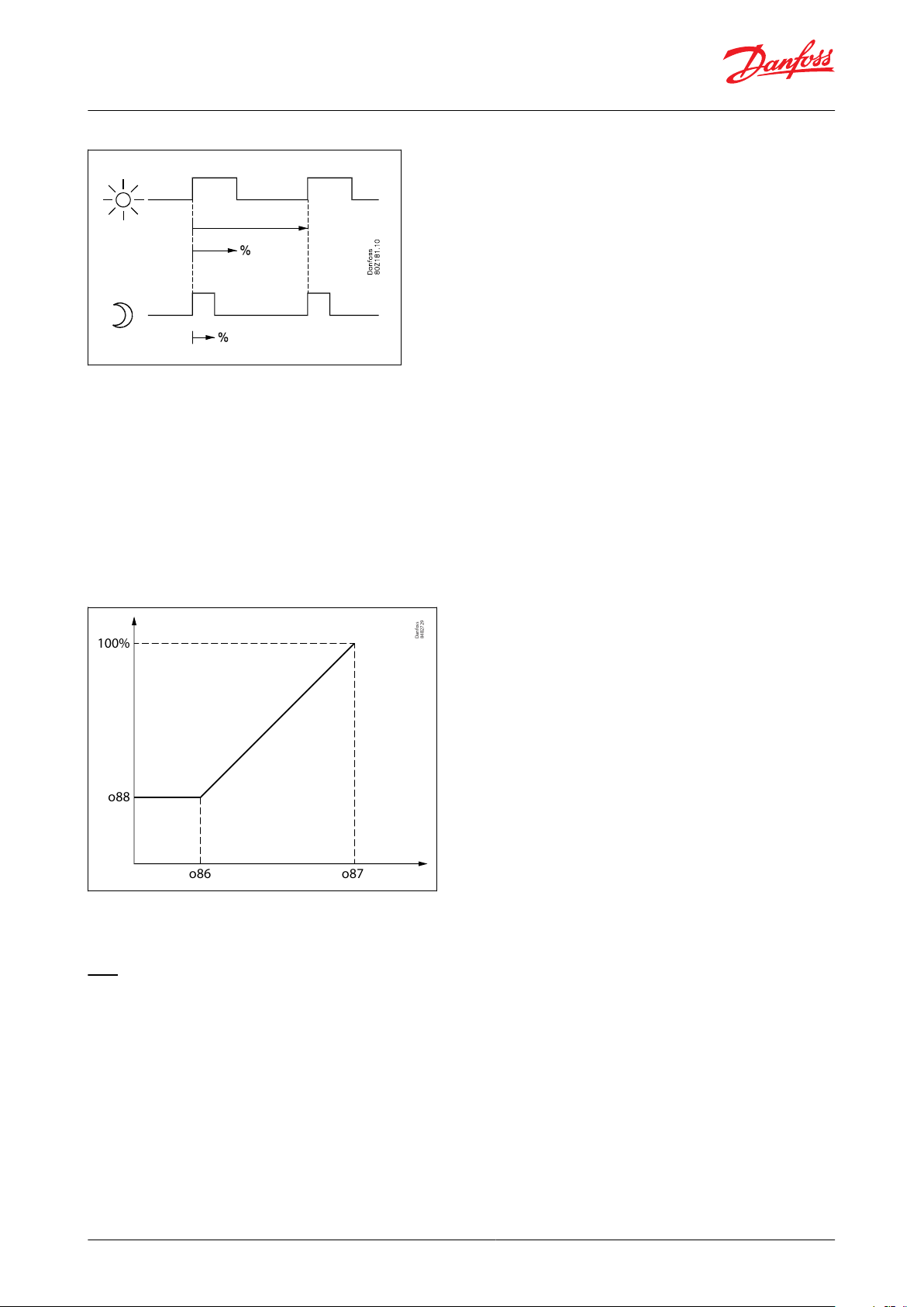
Pulse control according to day and night
Various ON periods can be set for day and night operation. A cycle time is set as well as the percentage part of the
period in which the rail heat is ON.
© Danfoss | Climate Solutions | 2022.03 BC364229688105en-000201 | 21
Page 22
Danfoss
84B2729
o88
o86
100%
o87
AK-CC55 Single Coil and AK-CC55 Single Coil UI
Figure 22: Rail heat control, day/night load
Pulse control according to dewpoint
In order to use this function, a system manager of the type AK-SM is required which can measure ambient
temperature and humidity to calculate dew point and distribute to the appliance controllers. For this the rail heat’s
ON period is controlled according to the distributed dewpoint.
Two dew point values are set in the appliance control:
• One where the eect must be max. i.e. 100%. (o87)
• One where the eect must be min. (o86)
At a dewpoint which is equal to or lower than the value in 086, the eect will be the value indicated in o88. In the
area between the two dew point values, the controller will manage the power to be supplied to the rail heat.
Figure 23: Rail heat control, dew point
During defrosting
During defrosting rail heat will be active, as selected in setting d27.
Fan
Pulse control
To obtain energy savings, it is possible to pulse control the power supply to the evaporator fans.
Pulse control can be accomplished in one of the following ways:
• during the thermostat’s cut-out period (cold room)
• during night operation and during the thermostat’s cut-out period (appliance with night blinds)
(The function is not actual when r14=2, i.e. modulating regulation).
A period of time is set as well as the percentage of this period of time where the fans have to be operating.
© Danfoss | Climate Solutions | 2022.03 BC364229688105en-000201 | 22
Page 23
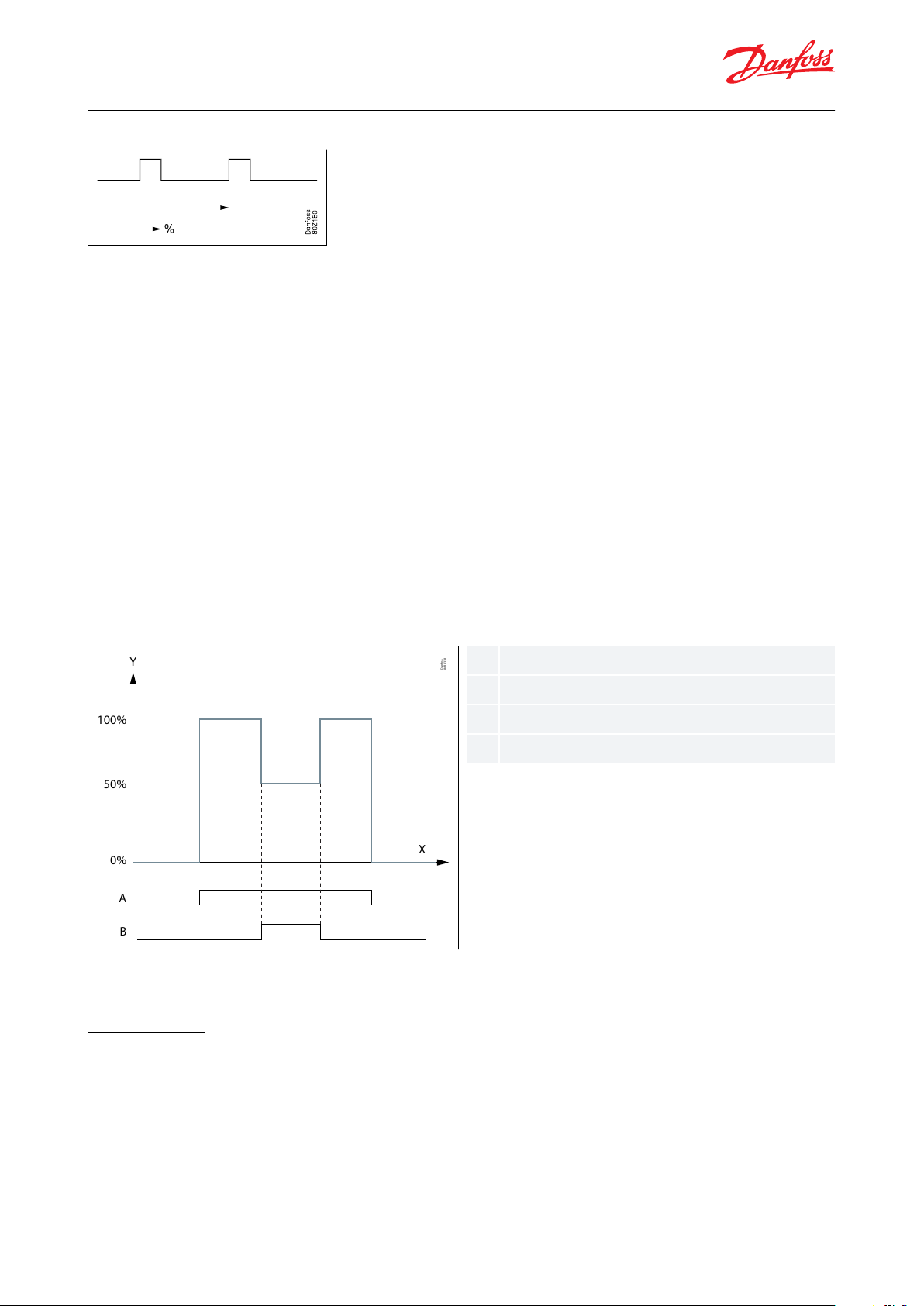
Y
X
100%
50%
0%
A
B
Danfoss
84B8318
XYABTime
Fan speed
Fan
Fan ECO
AK-CC55 Single Coil and AK-CC55 Single Coil UI
Figure 24: Fan cycle time
Cut-out of fans during plant breakdowns
If the refrigeration in a breakdown situation stops, the temperature in the cold room may rise quickly as a result of
the emission of heat from large fans. In order to prevent this situation, the controller can stop the fans if the
temperature at S5 exceeds a set limit value. The fans will start running again when the S5 temperature has dropped
2K below the set limit. (The function can also be used as a type of MOP function. Here the load on the compressors
is limited until the S5 temperature has fallen below the congured value).
Fan ECO operation (only custom set-up)
Fan ECO operation is used to reduce fan speed during night operation – typically on cabinets with night blinds.
The function is enabled when a relay has been congured for Fan ECO function in one of the applications with
custom set-up of relay functions.
The fan economy control (fan speed) is controlled via the two fan outputs:
• Fan output
• Fan Eco output
If the Fan output is activated, then the fan is running with 100% speed.
If the Fan ECO output is also activated, then the fan is running with reduced speed (typically 50%).
If both fan outputs are de-activated, then the fans are stopped.
Figure 25: Fan ECO control – Fan speed reduced to 50% during night operation
The fans will always run with full speed during day operation, rst stage of case cleaning, defrost, forced cooling and
when air heating is active.
Light function
The function can be used for controlling the light in a refrigeration appliance or in a cold room. It can also be used
for controlling a motorised night blind.
The light function can be dened in several ways:
© Danfoss | Climate Solutions | 2022.03 BC364229688105en-000201 | 23
Page 24

AK-CC55 Single Coil and AK-CC55 Single Coil UI
1.
The light is controlled via the day/night function. A digital input setup for light control can switch light ON, if the
light is switched o during night
2.
The light is controlled by a system manager via the parameter o39. A digital input setup for light control can
switch light ON, if the light is switched o by the system manager.
3.
Light is controlled via the door switch. Light is switched ON when door is opened and switched OFF 2 minutes
after the door has been closed.
4.
Like option 2, but here the light is switched ON automatically if the communication to the system manager has
been lost for 15 minutes
5.
Light is only controlled via a digital input setup for light control
The light load must be connected to the NC terminals on the relay.
This ensures that the light remains ON in the appliance if power to the controller should fail.
A setting denes how light is controlled when regulation is stopped via r12 Main switch = OFF (see o98). The light is
switched o when the appliance cleaning function is activated.
Night blind
Motorised night blinds can be controlled automatically from the controller either through the custom set-up night
blind output or via the NO connector on the light relay. The night blinds will follow the status of the light function.
When the light is switched on, the night blinds open, and when the light is switched o, the night blinds close
again. When the night blinds are closed, it is possible to open them using a switch signal on the digital input. If this
pulse signal is activated, the night blinds will open and the refrigeration appliance can be lled with new products.
If the pulse signal is activated again, the blinds close.
When the night blind function is used, the thermostat function can control with dierent weighting between the S3
and S4 sensors. A weighting during day operation and another when the blind is closed.
A night blind is opened when the appliance cleaning function is activated.
A setting can dene that the night blind is opened when "r12" (Main switch) is set to o (see o98).
When the night blind rolls down, the fan will be stopped for the set time. The night blind can thereby roll down to
the correct position.
Humidity control
In application 8 when setup for room control it is possible to dene if humidity control should be done via a
humidier or a dehumidier.
When humidity control is enabled, the second display will read out the actual humidity.
The controller measures the humidity via a 0 – 10 V signal from a humidity sensor and by means of a DO relay it can
activate a humidier or a de-humidier.
High and low humidity alarm limits can be set to generate a humidity alarm.
Humidity control is disabled when main switch is OFF, at manual control, at case shutdown, at forced closing mode,
at door open, if cooling is stopped, at humidity sensor error and at case cleaning.
It is possible to dene whether humidity control is enabled during defrost or not.
© Danfoss | Climate Solutions | 2022.03 BC364229688105en-000201 | 24
Page 25

Danfoss
80G8330
y
x
A
B
C
xyABC
Time
Temperature
Humidity max temp. dierence
Humidity min temp. dierence
Humidity control enabled
Danfoss
80G8221
y
x
A
SP
B
100%
xyASPB
Time
Humidity
Humidity dierence
Setpoint
Humidier
Danfoss
80G8332
y
x
A
100%
SP
B
xySPAB
Time
Humidity
Setpoint
Humidity dierence
Dehumidier
AK-CC55 Single Coil and AK-CC55 Single Coil UI
Figure 26: Humidity control
A Max and Min temperature range can be dened wherein the humidity control is enabled. Upper and lower
dierential is xed at 1K.
It can be dened whether humidity control is active during defrost or not.
Figure 27: Humidier control
If the humidity gets below the SP, then humidication is started via a DO signal to a humidier.
If the humidity increases to SP + humidity dierential, then humidication is stopped.
Figure 28: Dehumidier control
If the humidity rises above the SP, then dehumidication is started via a DO signal to a dehumidier.
If the humidity drops below the SP – Humidity dierential, then dehumidication is stopped.
© Danfoss | Climate Solutions | 2022.03 BC364229688105en-000201 | 25
Page 26

Danfoss
84B8269
A
r01
r01
t
º C
r62
B
C
ABC
Refrigeration
Neutral zone
Heat
Function
Input / Settings menu
Setting
DI1
DI2
DI3
o02
o37
o84
None+++0
DI Status+++1
Door function+++2
Door alarm+++3
Defrost start+++4
Main switch+++5
Night setback+++6
Thermostat band
+++
7
Alarm at closed++
8
Alarm at open++
9
Case cleaning+++10
Forced cooling+++11
Open blinds+++12
Coordinated defrost
+
13
Forced closing+++14
Shutdown+++15
Light control+++16
Leak detection+++20
Adaptive liquid control
+++
21
Valve driver alarm at open
++22
Fan alarm at open
++23
Door fan stop+++29
Oil recovery+++30
AK-CC55 Single Coil and AK-CC55 Single Coil UI
Heating function (only with custom set-up)
The heating function is used to prevent the temperature from becoming too low, e.g. in a cold room, etc. The limit
for when the heating function cuts o is set as an oset value below the current cut-out limit for the refrigeration
thermostat. This ensures that refrigeration and heating do not occur simultaneously. The dierence for the heating
thermostat has the same value as for the refrigeration thermostat. To prevent that the heating thermostat cuts in
during short-term drops in air temperature, a time delay can be set for when to change from refrigeration to
heating.
Figure 29: Heating function
Digital inputs
There are two digital inputs, DI1 and DI2, with dry contact function, and one digital input DI3 with high voltage
signal.
They can be used for the following functions:
Table 5: Function table and DI settings
© Danfoss | Climate Solutions | 2022.03 BC364229688105en-000201 | 26
Page 27

Danfoss
84B8238
AK-CC55 Single Coil and AK-CC55 Single Coil UI
Example: If DI1 is to be used to start a defrost, o02 must be set to 4.
Forced closing
The AKV valves can be closed with an external signal ("Forced closing").
The function must be used in connection with the compressor’s safety circuit, so that there will be no injection of
liquid into the evaporator when the compressor is stopped by the safety controls and cannot start again (however
not at low pressure – LP).
Via a setting (see o90 Fan at forced closing) it is possible to dene whether the fan should be ON or OFF during
forced closing and whether an ongoing defrost is suppressed (i.e. put in standby position for a period of up 10
minutes before it is cancelled) - this feature can be used in CO2 systems to eliminate excessive heating while
compressors cannot run.
The signal can be received from the DI-input or via the data communication.
Door contact
The door contact function can via the digital inputs be dened for two dierent applications:
Alarm monitoring:
The controller monitors the door contact and delivers an alarm message if the door has been opened for a longer
period than the set alarm delay.
Alarm monitoring and stop of refrigeration:
When the door is opened, the refrigeration is stopped, i.e. the injection, the compressor and the fan are stopped and
light switches on. If the door remains open for a longer time than the set restart time, refrigeration will be resumed.
This will ensure that refrigeration is maintained even if the door is left open or if the door contact should be
defective. If the door remains open for a longer period than the set alarm delay, an alarm will also be triggered.
Alarm monitoring and stop of fans:
When the door is opened, only the fans are stopped. If the door remains open for a longer time than the set alarm
delay, an alarm is triggered and the fans will start running again.
Display
The controller has one or two plugs for an external display.
One of the following display types can be connected to a plug:
• AK-UI55 Info (temperature display)
• AK-UI55 Set (temperature display and operation)
• AK-UI55 Bluetooth (temperature display and app interface)
The connection between the display and the controller must be made using an AK-UI55 cable.
The distance between the controller and the display must not exceed 100 m.
If there are two external displays, it will be the sum of the two distances that cannot exceed 100 m.
Figure 30: Controller with two displays
© Danfoss | Climate Solutions | 2022.03 BC364229688105en-000201 | 27
Page 28

Master control function
Description
MC Ther. toggle
Master control signal used for switching case load ON/OFF depending on the load condition
MC Load request
Master control signal used to control the load balance between multiple case controllers on the same suction line
MC Max. Te oset
Requested oset to actual evaporating temperature in order to keep the air temperature at the actual setpoint
MC Liquid control
Master control signal allowing switch to adaptive liquid control
MC Night setback
Master control signal for changing between day and night time operation
MC Case shutdown
Master control signal used to shut down a case for a time period. During shutdown there will be no alarm monitoring
MC Forced closing
Master control signal that will close the injection valve
MC Forced cooling
Master control signal that will provide forced cooling
MC Defrost start
Master control signal for starting a defrost. At adaptive defrost the defrost might be skipped if the defrost is not needed
MC Defrost state
Read out the actual state of the defrost
MC Hold after defrost
Master control signal used for co-ordinated defrost control to hold cabinets from returning to normal refrigeration after a defrost
until all cabinets have terminated defrost
MC Stop defrost
Master control signal used to prevent a defrost start in a controller.
MC Request next defrost
Master control signal used by system manager to see if a controller is requesting that the next defrost has to be carried out
MC Light signal
Master control signal for control of light via a data communication signal from the system manager
MC Actual dewpoint
Master control signal sending the actual measured dewpoint from the system manager to the controller over the network.
MC Tc temp. mean
Master control signal distributing the condensing temperature signal to the case controllers that are using adaptive defrost. At transcritical CO2 sites the receiver pressure is distributed to the case controllers. This function needs to be set up in the system manager.
MC Po load factor
Calculated load factor for the refrigerated appliance. Used for suction pressure optimization.
MC Key/Bluetooth lock
Master control signal that will lock down all Bluetooth data communication and optionally also lock the display keyboard (parameter P89)
MC Min. delta T
Required minimum delta temperature across evaporator (S3 - Te) in order to keep the air temperature at the actual setpoint
MC Oil Recovery
Master control signal used for starting and stopping an oil recovery sequence
AK-CC55 Single Coil and AK-CC55 Single Coil UI
Override
The controller contains a number of override functions which can be used together with Master Control functions in
the Danfoss gateway/system manager:
Table 6: Override functionality
© Danfoss | Climate Solutions | 2022.03 BC364229688105en-000201 | 28
Page 29

Danfoss
84B8277
S₆
S₄
S₃
S₅
S₂
S₃
S₆
S₅
S₄
AK-CC55 Single Coil and AK-CC55 Single Coil UI
Applications
The chapter outlines application examples:
• Standard display case
• Cases with one valve, one evaporator and two refrigeration sections
• Cases with one valve, two evaporators and two refrigeration sections
• Cold rooms
An application setting will congure inputs and outputs so that the controller’s operation interface is reecting the
selected application.
In application 9, users can custom dene the functions of relay 2 (DO1 is always AKV), e.g.:
• Controlling two compressors
• Controlling the night blind
• Controlling the heat function
• ECO operations of fans
Figure 31: Standard display case, upright or normal, with
one evaporator
Figure 32: Back-to-back cabinet with one evaporator
Figure 33: Back-to-back cabinet with two evaporators and
one AKV valve
© Danfoss | Climate Solutions | 2022.03 BC364229688105en-000201 | 29
Page 30

40
41
42
5V
s
AI1
43
44
AI2
45
46
AI3
47
48
AI4
49
50
AI5
51
52
AI6
53
54
DI1/
AI7*
60
61
DI2
70
71
AO1*
PWM
83
84
85
B
A
MODBUS
115 - 230V AC
L
N
1
2
3
8
9
7
10
11
12
DO2
13
14
DO3
15
16
17
DO4
18
19
20
DO5
21
22
DO6
115-230V AC
30
31
DI3
Danfoss
84B3234
Application 1-3
Plugin cabinets. Cabinets with dierent output combinations of alarm, rail heat and light.
Application 4
Remote cabinet including alarm, rail heat, defrost, light and fan.
Application 5
Remote hot gas defrost with suction, drain and hot gas valve.
Application 6
Back-to-back cabinet with one evaporator.
Application 7
Back-to-back cabinet with two evaporators.
Application 8
Cold storage room with defrost and simple humidity control.
Application 9
Custom
dened application, where the outputs can be congured according to custom requirements
No.
Application description
DO1
DO2
DO3
DO4
DO5
DO6
AO1
1
Plug-in cabinet
2
Plug-in cabinet
3
Plug-in cabinet
4
Remote cabinet
5
Remote Hot gas defrost
(Suction)
(Drain)
(Hot gas)
6
Back-to-back cabinet
7
Back-to-back cabinet
B
A
8
Cold storage room
humidity
9
User def. cong.
User def.
User def.
User def.
User def.
User def.
AK-CC55 Single Coil and AK-CC55 Single Coil UI
Figure 34: Cold room conguration with door and light
heat control function
AK-CC55 connections and application options
Upper and lower connection labels are laid out as shown in gure:
Figure 35: Electrical connections AK-CC55 Single Coil
AK-CC55 Single Coil is optimised for control of one expansion valve + dierent combinations of light, rail heat and
alarm relays. It has 6 Digital Outputs (DO), known as DO1 – DO6, one Analogue Output (AO), known as AO1, 6
Analogue Inputs (AI), known as AI1 – AI6, an input that can be used as either DI1 (Digital Input) or AI7 (Sensor Input),
and 2 Digital Inputs, known as DI2 - DI3. AI7 (DI1) can be congured as S5B defrost sensor in application 1-6 and
application 9.
DO1 will be congured for a liquid line solenoid valve if the analogue output AO1 is congured for control of a
stepper valve driver.
Table 7: The controller covers the following nine applications:
Table 8: Application with digital and analogue output specication
© Danfoss | Climate Solutions | 2022.03 BC364229688105en-000201 | 30
Page 31

Pe
Evaporating pressure
S2
Gas outlet of evaporator
S3
Return air temperature
S4
Discharge air temperature
S5
Evaporator temperature
S6
Product temperature
S3B
Return air temperature on second cooling section
S5B
Evaporator temperature on second evaporator or extra evaporator sensor on single evaporator
RH%
Relative humidity sensor
No.
Application description
AI1
AI2
AI3
AI4
AI5
AI6
AI7/DI1
DI2
DI3
1
Plug-in cabinet
PeS2S3S4S5S62
Plug-in cabinet
PeS2S3S4S5S63
Plug-in cabinet
PeS2S3S4S5S64
Remote cabinet
PeS2S3S4S5S65
Remote Hot gas defrost
PeS2S3S4S5S66
Back-to-back cabinet
PeS2S3S4S5
S3B
7
Back-to-back cabinet
PeS2S3S4S5
S3B
S5B
8
Cold storage room
PeS2S3S4S5S6RH%
9
User def. cong.
PeS2S3S4S5
S6
115 – 230 V AC
AKV Alarm Comp. Defrost Light Fan
DI3
115 – 230 V AC
1 2 3 7 8 9 10 11 12 13 14 21 22 30 3115 16 17 18 19 20
L N
40
5V
s
Pe
0 – 10 V/
PWM
S2 S3 S4 S5 S6 DI1/
AI7
DI2 AO1
1
41 42 43 44 45 46 47 48 49 50 51 52 53 54 60 61 70 71 83 84
B-A
+
MODBUS
85
P
1 3 2
Danfoss
84B3247
AK-CC55 Single Coil and AK-CC55 Single Coil UI
= Optional use
Table 9: Sensor description
Table 10: Application with digital and analogue output specication
= Optional use
Application set-ups and IO connections
Figure 36: Connections for application 1
© Danfoss | Climate Solutions | 2022.03 BC364229688105en-000201 | 31
Page 32

115 – 230 V AC
AKV Railheat Comp. Defrost Light Fan
DI3
115 – 230 V AC
1 2 3 7 8 9 10 11 12 13 14 21 22 30 3115 16 17 18 19 20
L N
40
5V
s
Pe
0 – 10 V/
PWM
S2 S3 S4 S5 S6 DI2 AO1
2
41 42 43 44 45 46 47 48 49 50 51 52 53 54 60 61 70 71 83 84
B-A
+
MODBUS
85
P
1 3 2
Danfoss
84B3248
DI1/
AI7
115 – 230 V AC
AKV Alarm Comp. Defrost Railheat Fan
DI3
115 – 230 V AC
1 2 3 7 8 9 10 11 12 13 14 21 22 30 3115 16 17 18 19 20
L N
40
5V
s
Pe
0 – 10 V/
PWM
S2 S3 S4 S5 S6 DI2 AO1
3
41 42 43 44 45 46 47 48 49 50 51 52 53 54 60 61 70 71 83 84
B-A
+
MODBUS
85
P
1 3 2
Danfoss
84B3249
DI1/
AI7
115 – 230 V AC
AKV Alarm Railheat Defrost Light Fan
DI3
115 – 230 V AC
1 2 3 7 8 9 10 11 12 13 14 21 22 30 3115 16 17 18 19 20
L N
40
5V
s
Pe
0 – 10 V/
PWM
S2 S3 S4 S5 S6 DI2 AO1
4
41 42 43 44 45 46 47 48 49 50 51 52 53 54 60 61 70 71 83 84
B-A
+
MODBUS
85
P
1 3 2
Danfoss
84B3250
DI1/
AI7
AK-CC55 Single Coil and AK-CC55 Single Coil UI
Figure 37: Connections for application 2
Figure 38: Connections for application 3
Figure 39: Connections for application 4
© Danfoss | Climate Solutions | 2022.03 BC364229688105en-000201 | 32
Page 33
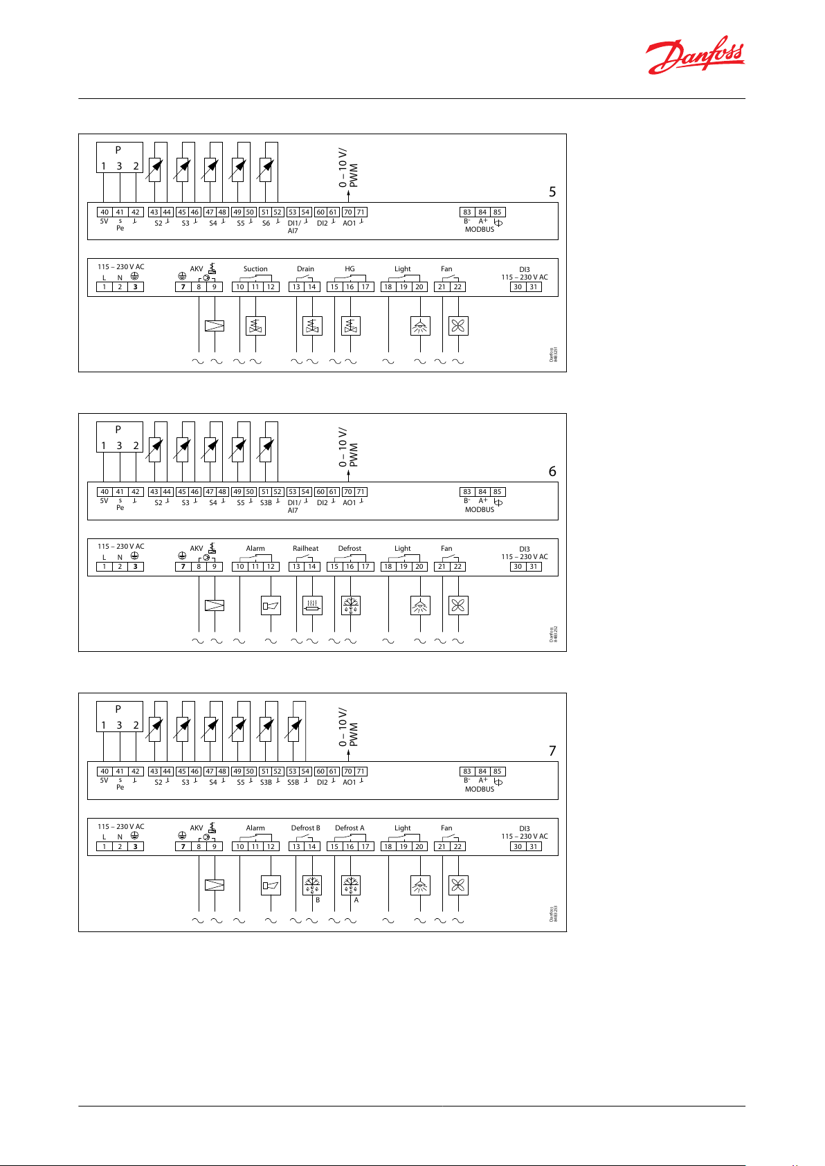
115 – 230 V AC
AKV Suction Drain HG Light Fan
DI3
115 – 230 V AC
1 2 3 7 8 9 10 11 12 13 14 21 22 30 3115 16 17 18 19 20
L N
40
5V
s
Pe
0 – 10 V/
PWM
S2 S3 S4 S5 S6 DI2 AO1
5
41 42 43 44 45 46 47 48 49 50 51 52 53 54 60 61 70 71 83 84
B-A
+
MODBUS
85
P
1 3 2
Danfoss
84B3251
DI1/
AI7
115 – 230 V AC
AKV Alarm Railheat Defrost Light Fan
DI3
115 – 230 V AC
1 2 3 7 8 9 10 11 12 13 14 21 22 30 3115 16 17 18 19 20
L N
40
5V
s
Pe
0 – 10 V/
PWM
S2 S3 S4 S5 S3B DI2 AO1
6
41 42 43 44 45 46 47 48 49 50 51 52 53 54 60 61 70 71 83 84
B-A
+
MODBUS
85
P
1 3 2
Danfoss
84B3252
DI1/
AI7
115 – 230 V AC
AKV Alarm Defrost B Defrost A Light Fan
DI3
115 – 230 V AC
1 2 3 7 8 9 10 11 12 13 14 21 22 30 3115 16 17 18 19 20
L N
AB
40
5V
s
Pe
0 – 10 V/
PWM
S2 S3 S4 S5 S3B S5B DI2 AO1
7
41 42 43 44 45 46 47 48 49 50 51 52 53 54 60 61 70 71 83 84
B-A
+
MODBUS
85
P
1 3 2
Danfoss
84B3253
AK-CC55 Single Coil and AK-CC55 Single Coil UI
Figure 40: Connections for application 5
Figure 41: Connections for application 6
Figure 42: Connections for application 7
© Danfoss | Climate Solutions | 2022.03 BC364229688105en-000201 | 33
Page 34

115 – 230 V AC
AKV Alarm Humidity Defrost Light Fan
DI3
115 – 230 V AC
1 2 3 7 8 9 10 11 12 13 14 21 22 30 3115 16 17 18 19 20
L N
40
5V
s
Pe
0 – 10 V/
PWM
S2 S3 S4 S5 S6 DI2 AO1
8
41 42 43 44 45 46 47 48 49 50 51 52 53 54 60 61 70 71 83 84
B-A
+
MODBUS
85
P
1 3 2
RH
U
0 10
Danfoss
84B3254
DI1/
AI7
115 – 230 V AC
AKV DO2 DO3 DO4
Custom set-up
DO5 DO6
DI3
115 – 230 V AC
1 2 3 7 8 9 10 11 12 13 14 21 22 30 3115 16 17 18 19 20
L N
40
5V
s
Pe
0 – 10 V/
PWM
S2 S3 S4 S5 S6 DI2 AO1
9
41 42 43 44 45 46 47 48 49 50 51 52 53 54 60 61 70 71 83 84
B-A
+
MODBUS
85
P
1 3 2
Danfoss
84B3266
DI1/
AI7
Danfoss
84B8271
AK-CC55 Single Coil and AK-CC55 Single Coil UI
Figure 43: Connections for application 8
Figure 44: Connections for application 9
Product identication
The controller is provided with labels from the factory, indicating a generic application. When selecting the required
application, specic labels are provided so that you can mount the relevant one.
The application number is indicated on the left-hand side of the labels. Use the label tting the selected application.
Some of the labels are applicable to multiple application options.
Figure 45: Product identication
© Danfoss | Climate Solutions | 2022.03 BC364229688105en-000201 | 34
Page 35
230 V AC (115 AC)
AO1/
PWM
60 61 70 71
SSR
Danfoss
80G8234
AK-CC55 Single Coil and AK-CC55 Single Coil UI
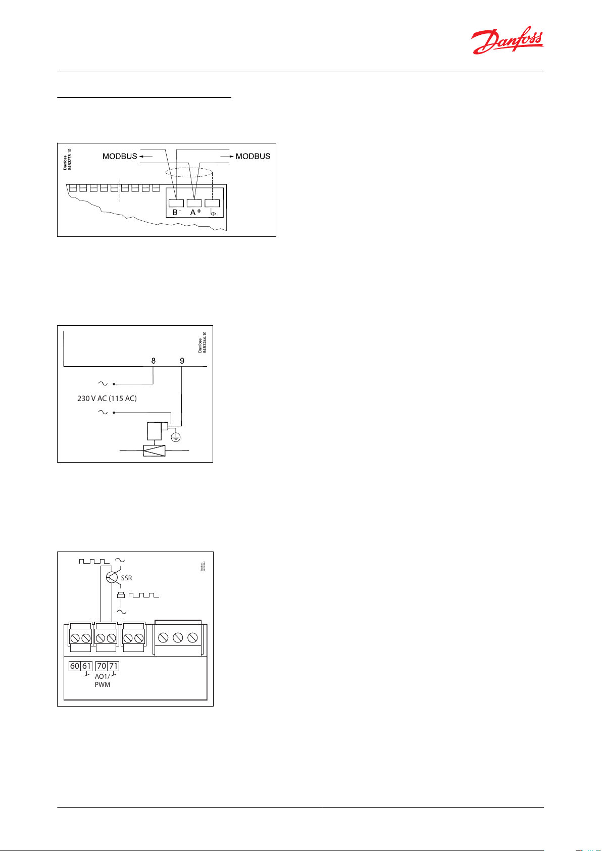
AK-CC55 Single Coil connections
Data communication
Figure 46: Data communication
IMPORTANT:
It is important that the installation of the data communication cable is performed correctly with sucient distance
to high voltage cables.
AKV info
Figure 47: AKV info
230 V or 115 V
AC coil
Max. 0.5 A
External solid state relay for rail heat
Figure 48: External solid state relay for rail heat
0 / 10 V Pulse Width Modulated (PWM)
Max. 15 mA.
© Danfoss | Climate Solutions | 2022.03 BC364229688105en-000201 | 35
Page 36
A
AKS 32R
B
out
C
ABC
Black
Brown
Blue
Danfoss
84B8239
AK-CC55 Single Coil and AK-CC55 Single Coil UI
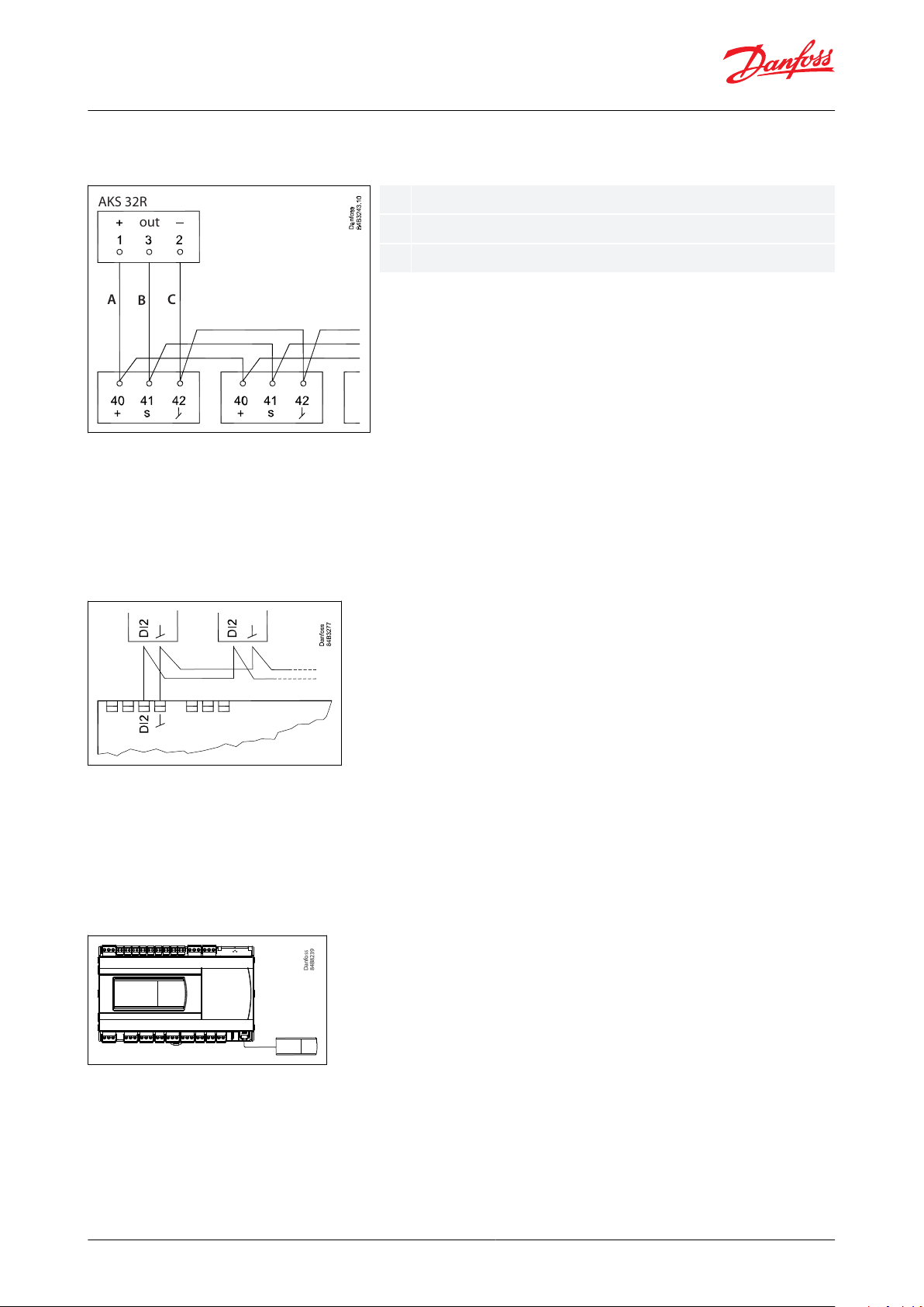
AKS 32R info
Figure 49: AKS 32R info
NOTE:
A ratiometric pressure transmitter with a 5 V, 10 – 90% voltage output signal must be used.
The signal from one pressure transmitter can be received by up to 10 controllers. There must not be a signicant
pressure drop from the pressure transmitter's position in the suction line to the individual evaporators.
Coordinated defrost via cable connections
Figure 50: Coordinated defrost via cable connections
Max. 10
The following controllers can be connected in this way:
EKC 204A, AK-CC 210, AK-CC 250, AK-CC 450, AK-CC 550 and AK-CC55.
Refrigeration is resumed at the same time when all controllers have terminated defrost.
External display AK-UI55
Figure 51: External display AK-UI55
Display
084B4075 / 084B4076 / 084B4077
Cable 3 m: 084B4078
Cable 6 m: 084B4079
(Total length: max. 100 m)
© Danfoss | Climate Solutions | 2022.03 BC364229688105en-000201 | 36
Page 37

AI1
Pressure transmitter
AKS 32R
Connect to terminal 40, 41 and 42.
(Use cable 060G1034: Black=40, Brown=41, Blue=42)
The signal from one pressure transmitter can be received by up to 10 controllers. But only if there are no signicant pressure drops between the evaporators to be controlled. See Figure 49: AKS 32R info.
NOTE:
When replacing AK-CC 550 with AK-CC55, S and ground must be switched.
AI2 - AI7
Primarily for temperature inputs
• S2
Pt 1000 ohm sensor AKS11, placed at the evaporator outlet
• S3, S4, S5
Pt 1000 AKS11, PTC 1000 EKS111, NTC5K EKS211, NTC10K EKS221 or a user-dened sensor type. All have to be of the same type.
• S3, return air sensor, placed in the warm air before the evaporator
• S4, discharge air sensor, placed in the cold air after the evaporator
(the need for either S3 or S4 can be selected in the conguration)
•
S5, defrost sensor, placed in the evaporator
• S6, Pt 1000 ohm sensor, food temperature sensor placed in-between the food products
(If the DI1 input is used for a temperature measurement e.g. S5B, it will appear as AI7.)
DI1
Digital input signal
The dened function is active when the input is short-circuited or opened, depending on the function dened in o02.
DI2
Digital input signal
The dened function is active when the input is short-circuited or opened, depending on the function dened in o37.
AO1
Analogue output signal
• Analogue 0 – 10 V
Can be used to drive an external stepper driver.
• Pulse width modulated signal
Can be used for fast pulse control of rail heat via an external power solid state relay.
MODBUS
For data communication:
• Terminal 83 = B-
• Terminal 84 = A+
• Terminal 85 = screen
NOTE:
When replacing AK-CC 550 with AK-CC55 A+, B- and shield must be switched.
Supply voltage
230 V AC or 115 V AC
DO1
• AKV valve
Connection of expansion valve type AKV, AKVA, AKVH or AKVP. The coil must be a 230 V or 115 V AC coil.
• Liquid line solenoid valve
Connection of normally closed valve in connection with stepper valve.
DO2
• Alarm
There is a connection between terminal 10 and 12 in alarm situations and when the controller is without power. DO2 has reinforced
insulation that can be used with 24 V.
• Light, Rail heat, Compressor, Night blind
There is connection between terminal 10 and 11 (10 and 12 at light) when the function is on.
• Suction line valve
There is connection between terminal 10 and 11 when the suction line must be open.
DO3
• Compressor, Rail heat, Defrost, Drain valve, Humidity
There is connection between terminal 13 and 14 when the function must be active.
DO4
• Defrost
There is connection between terminal 15 and 16 when defrosting takes place.
• Hot gas
There is connection between terminal 15 and 16 when the hot gas valves must open.
NOTE:
When replacing AK-CC 550 with AK-CC55, wires must be switched.
DO5
• Light
There is connection between terminal 18 and 20 when the function must be active.
• Rail heat
There is connection between terminal 18 and 19 when the rail heat must be on.
DO6
• Fan
There is connection between terminal 21 and 22 when the fan is on.
DO2-DO6 + AO1 and
Application 9
Here, the dierent outputs can be custom dened in q02-q09
DI3
Digital input signal
The signal must have a voltage of 0 / 230 V AC (115 V AC)
The function is dened in o84.
AK-CC55 Single Coil and AK-CC55 Single Coil UI
Connections
Table 11: Connection details
© Danfoss | Climate Solutions | 2022.03 BC364229688105en-000201 | 37
Page 38

AK-CC55 Single Coil and AK-CC55 Single Coil UI
Display (RJ12 plug)
If external readings/operation of the controller is required, a display can be connected. If there is no display on the
front, two external displays can be connected. For one display the max. cable length is 100 m. For two displays the
sum of the two cable lengths must not exceed 100 m.
NOTE:
When replacing AK-CC 550 with AK-CC55, AKA 16X remote displays and cables have to be replaced with new AKUI55 displays and cables.
Electric noise
Cables for sensors, low voltage DI inputs and data communication must be kept separate from other high voltage
cables:
• Use separate cable trays
• Keep a distance between cables of at least 10 cm
• Long cables at the low voltage DI input should be avoided
Installation considerations
Accidental damage, poor installation, or site conditions, can give rise to malfunctions of the control system, and
ultimately lead to a plant breakdown.
Every possible safeguard is incorporated into our products to prevent this. However, a wrong installation could still
present problems. Electronic controls are no substitute for normal, good engineering practice.
Danfoss will not be responsible for any goods, or plant components, damaged as a result of the above defects. It is
the installer's responsibility to check the installation thoroughly, and to t the necessary safety devices.
Special reference is made to the necessity of signals to the controller when the compressor is stopped and to the
need of liquid receivers before the compressors.
Your local Danfoss agent will be pleased to assist with further advice, etc.
Replacing AK-CC 550 with AK-CC55
NOTE:
Be aware when exchanging an AK-CC 550 controller with a new AK-CC55 controller - new wiring principles!
© Danfoss | Climate Solutions | 2022.03 BC364229688105en-000201 | 38
Page 39

AK-CC 550
AK-CC55
Pressure sensor has new connection – signal and ground are switched
SPDT relays have a new wiring scheme – NO and NC terminals are switched (e.g. defrost
heater on when it should be o)
Modbus has new connection scheme (A,B and screen)
New AK-UI55 displays and cables with 6 wires vs. 3 wires for EKA 16x
AK-CC55 Single Coil and AK-CC55 Single Coil UI
Table 12: Replacing AK-CC 550 with AK-CC55
• AK-CC55 does not support two EEC coils connected to one AKV output.
• Pressure transmitter can be shared between AK-CC 550 and AK-CC55.
• DI2 defrost coordination can be wired between AK-CC 550 and AK-CC55.
© Danfoss | Climate Solutions | 2022.03 BC364229688105en-000201 | 39
Page 40

012
The display keys are always operative
The display keys will be locked automatically when not used for some time and the keyboard must be
unlocked by pressing the arrow-up and arrow-down keys at the same time.
The display keys will be locked and unlocked by means of a master control signal from the System Manager.
AK-CC55 Single Coil and AK-CC55 Single Coil UI
Operation
The controller can be operated in dierent ways depending on the user interface.
The following options are available:
• Via data commmunication
• Via AK-UI55 Setting Display
• Via AK-UI55 Bluetooth display
Operation via data communication
Via system manager's display
All AK-CC55 controllers can be operated from a central location, e.g. AK-SM 800.
Data communication is to take place via MODBUS or Lon.
Via system manager and service tool
Operation can also be performed from a central location with PC software "Service Tool" connected to a system
manager AK-SM 720 via MODBUS or Lon.
Programming via KoolProg
Programming by use of PC software type KoolProg® via interface MMIMYK connected to RJ12 display connector.
Direct operation
Operation via AK-UI55 setting display
The display can be located on the front of the controller or at a distance of up to 100 metres from the controller.
Smart phone and app via AK-UI55 Bluetooth display
The "AK-CC55 connect" app is used for smart phone operation.
AK-CC55 connect can be downloaded freely to a compatible iOS/Android smartphone device.
The display can be placed at a distance of up to 100 metres from the controller.
Menu operation is established by activating Bluetooth communication to the app.
Operation via AK-UI55 Set
Display AK-UI55 Set
The values will be shown with three digits, and with a setting you can determine whether the temperature is to be
shown in °C or in °F.
To prevent any passing-by user from making unauthorized changes, the access to the display menu is restricted by
access codes.
Besides this, the parameter P89 provides the following options for handling of the display keyboard:
© Danfoss | Climate Solutions | 2022.03 BC364229688105en-000201 | 40
Page 41

ABCDE
F
Danfoss
84B8325
D
C
A
B
E
F
Lights up in event of: Energy optimization, Cool-
ing, Defrosting, Fan operation
Lights in event of alarm
Long press (3 seconds) on alarm button alarm —
relay is reset — alarm code displayed — e.g. “A1”
Long press (3 seconds) gives access to the infor-
mation menu “InF”
Up arrow / Down arrow / Arrow to left: Navigation
in the menu and setting of values.
Long press (3 seconds) will start a defrost, “-d-” is
shown in the display. Ongoing defrosting can be
stopped by a long press.
SET: Long press (3 seconds) gives access to the
“SEt” menu. If the operation is locked with a pass-
word, “PS” is shown. Enter the code.
Shows the setting for a chosen parameter / saves a
changed setting. Short press gives access to enter-
ing of the thermostat’s cut-out limit.
Display readout
Denomination
-d-
Defrost is in progress
Err
The temperature cannot be displayed due to a sensor error
Err1
The display cannot load data from the controller. Disconnect and then reconnect the display
Err2
Lost display communication
ALA
The alarm button is activated. The rst alarm code is then shown
- - -
At top position of the menu or when max. value has been reached, the three dashes are shown in the top of the display
- - -
At bottom position of menu or when min. value has been reached, the three dashes are shown in the bottom of the display
Loc
The menu operation is locked. Unlock by pressing (for 3 seconds) on the ‘up arrow’ and ‘down arrow’ simultaneously
UnL
The menu operation is unlocked
- - -
The parameter has reached min. or max. limit
PS
A password is required for access to the menu
Fan
Appliance cleaning has been initiated. The fans are running
OFF
Appliance cleaning is activated and the appliance can now be cleaned
OFF
The main switch is set to O
SEr
The main switch is set to service / manual operation
CO2
Flashes: Will display in event of a refrigerant leakage alarm, but only if the refrigerant is set up for CO
2
AK-CC55 Single Coil and AK-CC55 Single Coil UI
Figure 52: Operating via AK-UI55 Set
Table 13: Messages provided by the display
Factory setting
If you need to return to the factory-set values, do the following:
• Cut o the supply voltage to the controller
• Keep up "∧" and down "∨" arrow buttons depressed at the same time as you reconnect the supply voltage
• When FAc is shown in the display, select "yes"
NOTE:
The OEM factory setting will either be the Danfoss factory settings or a user dened factory setting if one has been
made.
The user can save his setting as OEM factory setting via parameter o67.
© Danfoss | Climate Solutions | 2022.03 BC364229688105en-000201 | 41
Page 42

(PS)
<
r12
<
o61
r-- o03
A-- r89
c-- r00
r15
r61
A36
o17
d--
o30
n--
o20
F--
o21
t--
d01
h--
d03
o--
d10
p--
d04
q--
d02
u--
<
<
SET
SET
cFg
Set
Danfoss
84B8272
SET button,
3 s: Configuration settings
PS: Password (if any)
Main switch
Menu groups
See also the following pages.
Application
MODBUS address
Food type
Cut-out temperature
Ther. sensor S4 %
Ther. sensor S4% night
Alarm sensor S4%
Display air S4%
Refrigerant type
Min. transmitter range
Max. transmitter range
Defrost method
Defrost interval
Defrost sensor
Max. defrost time
Defrost stop temperature
(Return)
(Return)
Danfoss
84B8279
<
Inf
StA SET
App SET
in SET
di1/
AI7
**
out SET
do1 Akv di2 **
buS SET do2
*
di3 **
SoF SET do3
*
AI1 PE
< do4
*
AI2 S2
do5
*
AI3 S3
do6
*
AI4 S4
AI5 S5
Ao1
*
AI6 **
<
Info button,
3 s: Information for service use
See control state message
Read output status
Read input status
See selected application
(Return)
(Return)
(Return)
Output status
When you want info on a relay
output, the dot will show
whether the relay is activated
(energized) for, e.g.:
do4 = not activated
do.4 = activated
MODBUS quality
See SW version
*
**
StA
The output's function (determined at
conguration). The DOs and AOs can also be
forced controlled from this menu, when r12 Main
switch has been set in position "service". Forced
control of a function can also be performed in
codes q11 to q27.
The input's function (determined at conguration).
See control state message in Table 49
AK-CC55 Single Coil and AK-CC55 Single Coil UI
Parameter groups when operating via display
Figure 53: SET button parameter list
Figure 54: Info button parameter list
Get a good start
With the following procedure you can start regulation very quickly:
1.
2.
3.
4.
5.
© Danfoss | Climate Solutions | 2022.03 BC364229688105en-000201 | 42
Open parameter r12 and stop the regulation (in a new and not previously set unit, r12 will already be set to 0
which means stopped regulation)
Select application based on the wiring diagrams on Page 31
Open parameter o61 and set the application number
For network. Set the address in o03
Then select a set of presets from the "Food type" help table
Page 43

Setting of presettings (r89).
After setting 1-5, setting is returned to 0.
12345
Food type
Vegetables
Milk
Meat/sh
Frozen food
Ice cream
Temperature (r00)
8 °C
0 °C
-2 °C
-20 °C
-24 °C
Max. temp. setting (r02)
10 °C
4 °C
2 °C
-16 °C
-20 °C
Min. temp. setting (r03)
4 °C
-4 °C
-6 °C
-24 °C
-28 °C
Upper alarm limit (A13)
14 °C
8 °C
8 °C
-15 °C
-15 °C
Lower alarm limit (A14)
0 °C
-5 °C
-5 °C
-30 °C
-30 °C
Upper alarm limit for S6 (A22)
14 °C
8 °C
8 °C
-15 °C
-15 °C
Lower alarm limit for S6 (A23)
0 °C
-5 °C
-5 °C
-30 °C
-30 °C
AK-CC55 Single Coil and AK-CC55 Single Coil UI
6.
Open parameter r89 and set the number for the array of presettings. The few selected settings will now be
transferred to the menu
7.
Set the desired cut-out temperature r00
8.
Set the weighted thermostat air temperature between S4 and S3 sensor r15
9.
Set the weighted thermostat air temperature between S4 and S3 during night operation r61
10.
Set the weighted alarm air temperature between S4 and S3 A36
11.
Set the weighted display readout between S4 and S3 o17
12.
Select refrigerant via parameter o30
13.
Set the pressure transmitter min. and max. range via parameter o20 and o21
14.
Set the desired defrost method in d01
15.
Set the interval time between defrost starts in d03
16.
Set the desired defrost sensor in d10
17.
Set the maximum defrost time in d04
18.
Set the defrost stop temperature in d02
19.
Open parameter r12 and start the regulation
20.
Go through the parameter list and change the factory values where needed
21.
Get the controller up and running on network:
◦ MODBUS: Activate scan function in system unit
◦ If another data communication card is used in the controller:
▪ Lon RS485: Activate the function o04
▪ Ethernet: Use the MAC address
Table 14: Food type settings
© Danfoss | Climate Solutions | 2022.03 BC364229688105en-000201 | 43
Page 44

R-W
RW*
If the operation is protected by one or more passwords, reading and setting the parameter will be limited to:
R or W
This setting can be seen with password no. _ or higher (3 is the highest level).
This setting can be performed with password no. _ or higher (3 is the highest level).
The asterisk indicates in which application from 1-9 the parameter is applicable.
Function
Values
R-W
Code123456789Min. value
Max. value
Fact. value
Cut-out 1
0-0
r00*********r03
r02
2.0 °C
Dierential 1
1-2
r01*********0.1 °C
20.0 °C
2.0 °C
Max cut-out limit
0-2
r02*********r03
50.0 °C
50.0 °C
Min cut-out limit
0-2
r03*********-60.0 °C
r02
-60.0 °C
Display readout adjustment
1-2
r04*********-10.0 °C
10.0 °C
0.0 °C
Temperature unit
0=Celsius, 1=Fahrenheit
1-2
r05*********010
S4 Air OFF evap. A - Adjustment
1-2
r09*********-10.0 °C
10.0 °C
0.0 °C
S3 Air ON evap. A - Adjustment
1-2
r10*********-10.0 °C
10.0 °C
0.0 °C
S5 Evaporator A - Adjustment
1-2
r11*********-10.0 °C
10.0 °C
0.0 °C
Main switch
-1=Manual, 0=Stop,
1=Start
0-2
r12*********-110
Night oset
1-2
r13*********-50.0 °C
50.0 °C
0.0 °C
Thermostat mode
1=ON/OFF, 2=Modulating
1-2
r14*********121
Thermostat sensor S4 %
1-2
r15*********0 %
100 %
100%
Melt interval
1-2
r16*********0 h
10 h
1 h
Melt period
1-2
r17*********0 min
30 min
5 min
S2 Gas outlet A - Adjustment
1-2
r19*********-10.0 °C
10.0 °C
0.0 °C
Cut-out 2
0-2
r21*********-60.0 °C
50.0 °C
2.0 °C
S3 Air ON evap. B - Adjustment
1-2
r53**
-10.0 °C
10.0 °C
0.0 °C
S6 product temp. - Adjustment
1-2
r59*******-10.0 °C
10.0 °C
0.0 °C
Thermostat sensor S4 %
night
1-2
r61*********0 %
100 %
100%
Air heater neutral zone
1-2
r62*0.0 °C
50.0 °C
5.0 °C
Air heater start delay
1-2
r63*0 min
240 min
240 min
Food type
0=None, 1=Vegetables,
2=Dairy, 3=Meat and sh,
4=Frozen food, 5=Ice
cream
1-2
(1)
r89*********050
Dierential 2
1-2
r93*********0.1 °C
20.0 °C
2.0 °C
S4 frost protection
1-2
r98*********-60.0 °C
50.0 °C
-60.0 °C
Function
Values
R-W
Code123456789Min. value
Max. value
Fact. value
Alarm delay A
1-2
A03*********0 min
240 min
30 min
Door open alarm delay
1-2
A04*********0 min
240 min
60 min
Alarm delay pull down A
1-2
A12*********0 min
240 min
90 min
AK-CC55 Single Coil and AK-CC55 Single Coil UI
AK-UI55 display menu (SW ver. 1.7x)
Thermostat
Table 15: Thermostat
(1)
(1)
In order to change this parameter the regulation must be stopped via the parameter r12 Main switch = OFF.
In order to change this parameter the regulation must be stopped via the parameter r12 Main switch = OFF.
Alarm settings
Table 16: Alarm settings
© Danfoss | Climate Solutions | 2022.03 BC364229688105en-000201 | 44
Page 45

Function
Values
R-W
Code123456789Min. value
Max. value
Fact. value
High alarm limit 1
1-2
A13*********-60.0 °C
50.0 °C
8.0 °C
Low alarm limit 1
1-2
A14*********-60.0 °C
50.0 °C
-30.0 °C
High alarm limit 2
1-2
A20*********-60.0 °C
50.0 °C
8.0 °C
Low alarm limit 2
1-2
A21*********-60.0 °C
50.0 °C
-30.0 °C
S6 High alarm limit 1
1-2
A22*******-60.0 °C
50.0 °C
8.0 °C
S6 Low alarm limit 1
1-2
A23*******-60.0 °C
50.0 °C
-30.0 °C
S6 High alarm limit 2
1-2
A24*******-60.0 °C
50.0 °C
8.0 °C
S6 Low alarm limit 2
1-2
A25*******-60.0 °C
50.0 °C
-30.0 °C
S6 alarm delay
1-2
A26*******0 min
240 min
60 min
Alarm delay DI 1
1-2
A27*******0 min
240 min
30 min
Alarm delay DI 2
1-2
A28*********0 min
240 min
30 min
Alarm sensor S4% A
1-2
A36*********0 %
100 %
100%
S6 alarm pull down delay
1-2
A52*******0 min
240 min
90 min
Alarm delay B
1-2
A53**
0 min
240 min
30 min
Use product sensor S6
0=No, 1=Yes
1-2
(1)
a01*******010
Function
Values
R-W
Code123456789Min. value
Max. value
Fact. value
Min ON time
1-2
c01****
0 min
30 min
0 min
Min OFF time
1-2
c02****
0 min
30 min
0 min
Delay between comp.
1-2
c05*0 s
999 s
5 s
Step control mode
1=Sequential, 2=Cyclic
1-2
c08*122
Comp. 2 ctrl. Th. band 2
0=OFF, 1=ON
1-2
c85*011
Function
Values
R-W
Code123456789Min. value
Max. value
Fact. value
Defrost method
0=None, 1=Electrical,
2=Hot gas, 4=Air/Ocycle
1-3
d01*********041
Defrost stop limit 1
1-2
d02*********0.0 °C
50.0 °C
6.0 °C
Defrost start interval
1-2
d03*********0 h
240 h
8 h
Max. defrost time 1
1-2
d04*********0 min
360 min
45 min
Time staggering power-up
1-2
d05*********0 min
240 min
0 min
Drip
o time
1-2
d06*********0 min
60 min
0 min
Fan start delay
1-2
d07*********0 min
60 min
0 min
Fan start temperature
1-2
d08*********-60.0 °C
10.0 °C
-5.0 °C
Fan control during defrost
0=OFF, 1=ON, 2=OFF at
drip, 3=OFF at high temp
1-2
d09*********031
Defrost stop method
0=Time, 1=S5 sensor, 2=S4
sensor, 3=S5A and S5B
1-2
d10*********030
Pump down delay
1-2
d16*********0 min
60 min
0 min
Drain delay
1-2
d17*0 min
60 min
0 min
Max. thermostat run time
1-2
d18*********0 h
240 h
0 h
Adaptive defrost mode
0=OFF, 1=Monitoring,
2=Skip day, 3=Skip day/
night, 4=Full adaptive
1-2
(1)
d21*********040
Hot gas injection delay
1-2
d23*0 min
60 min
0 min
Min. defrost time
1-2
d24*********0 min
d04
0 min
Rail heat during defrost
0=OFF, 1=ON, 2=Normal
control
1-2
d27*********021
Defrost stop limit 2
1-2
d28*********0.0 °C
50.0 °C
6.0 °C
Max. defrost time 2
1-2
d29*********d24
360 min
45 min
Display delay after defrost
1-2
d40*********5 min
240 min
30 min
Fan stop temperature
1-2
d41*********-20.0 °C
20.0 °C
0.0 °C
AK-CC55 Single Coil and AK-CC55 Single Coil UI
(1)
(1)
In order to change this parameter the regulation must be stopped via the parameter r12 Main switch = OFF.
In order to change this parameter the regulation must be stopped via the parameter r12 Main switch = OFF.
Compressor
Table 17: Compressor
Defrost
Table 18: Defrost
© Danfoss | Climate Solutions | 2022.03 BC364229688105en-000201 | 45
Page 46

Function
Values
R-W
Code123456789Min. value
Max. value
Fact. value
Max. superheat limit
1-2
n09*********n10
20.0 °C
12.0 °C
Min. superheat limit
1-2
n10*********2.0 °C
n09
3.0 °C
MOP temperature
1-2
n11*********-60.0 °C
15.0 °C
15.0 °C
AKV Period time
1-2
(1)
n13*********3 s
6 s
6 s
Function
Values
R-W
Code123456789Min. value
Max. value
Fact. value
Fan stop high S5 temp.
1-2
F04*********-60.0 °C
50.0 °C
50.0 °C
Fan pulsing mode
0=No pulsing, 1=Pulsing
cut-out, 2=Pulsing cut-out
night
1-2
F05*********020
Fan period time
1-2
F06*********1 min
30 min
5 min
Fan ON cycle
1-2
F07*********0 %
100 %
100%
Function
Values
R-W
Code123456789Min. value
Max. value
Fact. value
Defrost schedule
0=No, 1=Yes
1-2
t00*********010
Def. start 1 - Hours
1-2
t01*********0 h
23 h
0 h
Def. start 1 - Minutes
1-2
t11*********0 min
59 min
0 min
Def. start 2 - Hours
1-2
t02*********0 h
23 h
0 h
Def. start 2 - Minutes
1-2
t12*********0 min
59 min
0 min
Def. start 3 - Hours
1-2
t03*********0 h
23 h
0 h
Def. start 3 - Minutes
1-2
t13*********0 min
59 min
0 min
Def. start 4 - Hours
1-2
t04*********0 h
23 h
0 h
Def. start 4 - Minutes
1-2
t14*********0 min
59 min
0 min
Def. start 5 - Hours
1-2
t05*********0 h
23 h
0 h
Def. start 5 - Minutes
1-2
t15*********0 min
59 min
0 min
Def. start 6 - Hours
1-2
t06*********0 h
23 h
0 h
Def. start 6 - Minutes
1-2
t16*********0 min
59 min
0 min
Time hours
0-1
t07*********0 h
23 h
0 h
Time minutes
0-1
t08*********0 min
59 min
0 min
Time date
0-1
t45*********1311
Time month
0-1
t46*********1121
Time year
0-1
t47*********0
100
0
Monday - Follow schedule
0=No, 1=Yes
1-2
t51*********011
Tuesday - Follow schedule
0=No, 1=Yes
1-2
t52*********011
Wednesday - Follow schedule
0=No, 1=Yes
1-2
t53*********011
Thursday - Follow schedule
0=No, 1=Yes
1-2
t54*********011
Friday - Follow schedule
0=No, 1=Yes
1-2
t55*********011
Saturday - Follow schedule
0=No, 1=Yes
1-2
t56*********011
Sunday - Follow schedule
0=No, 1=Yes
1-2
t57*********011
AK-CC55 Single Coil and AK-CC55 Single Coil UI
(1)
(1)
In order to change this parameter the regulation must be stopped via the parameter r12 Main switch = OFF.
In order to change this parameter the regulation must be stopped via the parameter r12 Main switch = OFF.
Injection control
Table 19: Injection control
(1)
(1)
In order to change this parameter the regulation must be stopped via the parameter r12 Main switch = OFF.
In order to change this parameter the regulation must be stopped via the parameter r12 Main switch = OFF.
Fan control
Table 20: Fan control
Defrost schedule
Table 21: Defrost schedule
© Danfoss | Climate Solutions | 2022.03 BC364229688105en-000201 | 46
Page 47

Function
Values
R-W
Code123456789Min. value
Max. value
Fact. value
Humidity cut-in
0-2
h23*0 RH%
100 RH%
70RH%
Humidity dierential
1-2
h24*1 RH%
30 RH%
5RH%
Humidity high alarm limit
1-2
h25*0 RH%
100 RH%
100RH%
Humidity low alarm limit
1-2
h26*0 RH%
100 RH%
0RH%
Humidity alarm delay
1-2
h27*0 min
240 min
60 min
Humidity ctrl. at defrost
0=No, 1=Yes
1-2
h28*010
Humidity sensor - Min signal
1-2
(1)
h29*0 RH%
h30
0RH%
Humidity sensor - Max signal
1-2
(1)
h30*h29
100 RH%
100RH%
Humidity control
0=None, 1=Humidier,
2=Dehumidier
1-3
(1)
h31*020
Humidity max. temp.
1-2
h32*h33
70.0 °C
70.0 °C
Humidity min. temp.
1-2
h33*-5.0 °C
h32
2.0 °C
Function
Values
R-W
Code123456789Min. value
Max. value
Fact. value
Delay of outputs at powerup
1-2
o01*********0 s
600 s
5 s
DI1 Conguration
0=None, 1=DI status,
2=Door function, 3=Door
alarm, 4=Defrost start,
5=Main switch, 6=Night
setback, 7=Thermostat
band, 8=Alarm at closed,
9=Alarm at open, 10=Case
cleaning, 11=Forced cooling, 12=Open blinds,
13=Coordinated defrost,
14=Forced closing,
15=Shutdown, 16=Light
control, 20=Leak detection,
21=Adaptive liquid control,
22=Valve driver, 23=Fan
alarm, 29=Door fan stop,
30=Oil recovery
1-2
(1)
o02*******0300
Network address
1-3
(1)
o03*********0
240
0
Service pin
0=OFF, 1=ON
1-2
o04*********010
Access code 3
3-3
o05*********0
999
0
Temperature sensor type
0=Pt 1000, 1=PTC 1000,
2=NTC 5k, 3=NTC 10k,
4=User-dened
1-3
(1)
o06*********040
Max. hold time
1-2
o16*********0 min
360 min
20 min
Display air S4%
1-2
o17*********0 %
100 %
100%
Pe Min range
1-3
(1)
o20*********-1.0 Bar
5.0 Bar
-1.0Bar
Pe Max range
1-3
(1)
o21*********6.0 Bar
200.0 Bar
12.0 Bar
AO1 Min. voltage
1-3
(1)
o27********
0.0 V
o28
0.0V
AO1 Max. voltage
1-3
(1)
o28********
o27
10.0 V
10.0 V
AK-CC55 Single Coil and AK-CC55 Single Coil UI
Humidity control
Table 22: Humidity control
(1)
(1)
In order to change this parameter the regulation must be stopped via the parameter r12 Main switch = OFF.
In order to change this parameter the regulation must be stopped via the parameter r12 Main switch = OFF.
Miscellaneous
Table 23: Miscellaneous
© Danfoss | Climate Solutions | 2022.03 BC364229688105en-000201 | 47
Page 48

Function
Values
R-W
Code123456789Min. value
Max. value
Fact. value
Refrigerant
0=Not seleted, 6=R13,
7=R13b1, 2=R22, 8=R23,
14=R32, 11=R114,
3=R134a, 12=R142b,
24=R170, 15=R227,
25=R290, 16=R401A,
18=R402A, 19=R404A,
21=R407A, 22=R407B,
20=R407C, 37=R407F,
49=R407H, 23=R410A,
32=R413A, 30=R417A,
31=R422A, 33=R422D,
34=R427A, 35=R438A,
40=R448A, 41=R449A,
48=R449B, 43=R450A,
44=R452B, 45=R454B,
9=R500, 4=R502, 10=R503,
17=R507, 36=R513A,
26=R600, 27=R600a,
5=R717, 28=R744,
46=R1233zdE, 38=R1234ze,
39=R1234yf, 47=R1234zeZ,
29=R1270, 42=R452A,
1=User dened display,
13=User dened
1-3
(1)
o30*********0490
DI2 Conguration
0=None, 1=DI status,
2=Door function, 3=Door
alarm, 4=Defrost start,
5=Main switch, 6=Night
setback, 7=Thermostat
band, 8=Alarm at closed,
9=Alarm at open, 10=Case
cleaning, 11=Forced cooling, 12=Open blinds,
13=Coordinated defrost,
14=Forced closing,
15=Shutdown, 16=Light
control, 20=Leak detection,
21=Adaptive liquid control,
22=Valve driver, 23=Fan
alarm, 29=Door fan stop,
30=Oil recovery
1-2
(1)
o37*********0300
Light control mode
1=Day and night, 2=Network, 3=Door switch,
4=Network (Fallback),
5=Digital input
1-2
o38********15
1
MC Light signal
0=OFF, 1=ON
1-2
o39********010Rail heat ON cycle day
1-2
o41*********0 %
100 %
100%
Rail heat ON cycle night
1-2
o42*********0 %
100 %
100%
Rail heat period time
1-2
o43*****6 min
60 min
6 min
Case cleaning mode
0=OFF, 1=Fans run,
2=Cleaning
0-1
o46*********020
Application mode
1=1. Comp/Alarm/Light,
2=2. Comp/Rail/Light, 3=3.
Comp/Alarm/Rail, 4=4.
Alarm/Rail/Light, 5=5. Hot
gas remote, 6=6. Dual with
1 evap., 7=7. Dual with 2
evap., 8=8. Cold room, 9=9.
Custom
1-3
(1)
o61*********191
Access code 2
2-2
o64*********0
999
0
Make new factory
0=OFF, 1=ON
3-3
(1)
o67*********010
AK-CC55 Single Coil and AK-CC55 Single Coil UI
© Danfoss | Climate Solutions | 2022.03 BC364229688105en-000201 | 48
Page 49
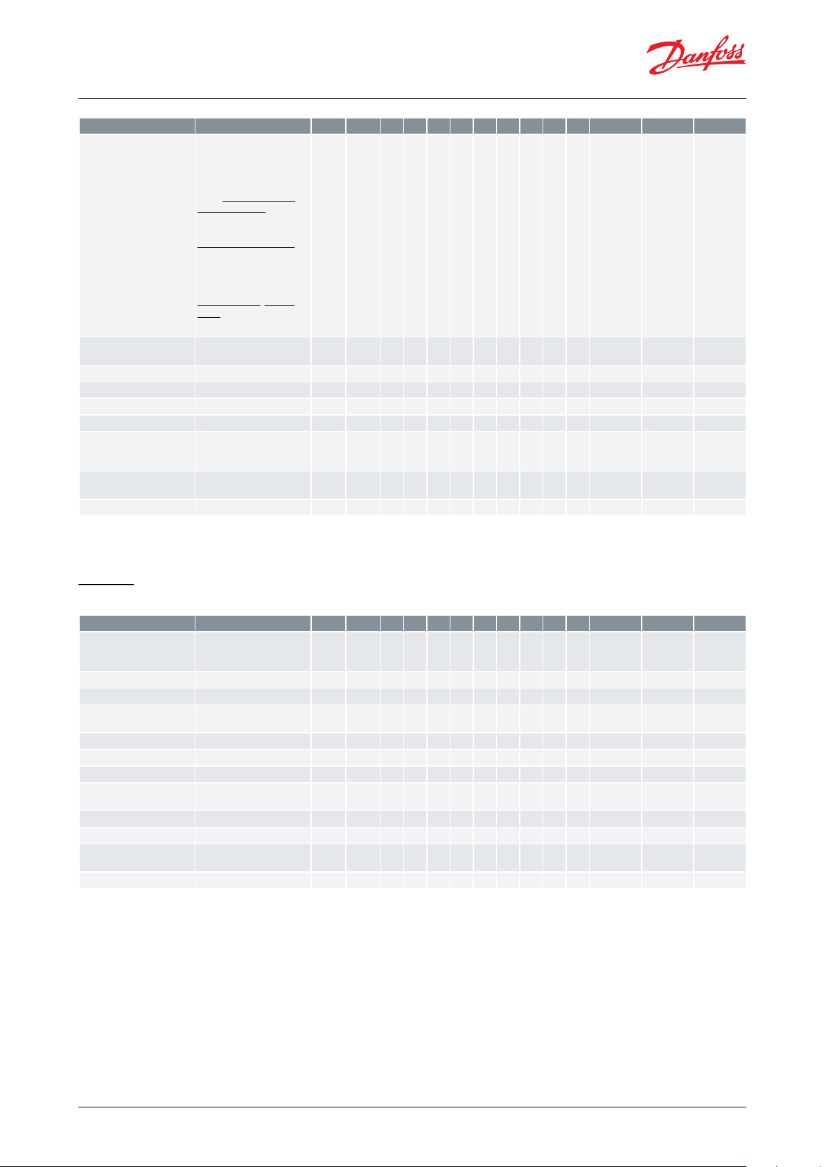
Function
Values
R-W
Code123456789Min. value
Max. value
Fact. value
DI3 Conguration
0=None, 1=DI status,
2=Door function, 3=Door
alarm, 4=Defrost start,
5=Main switch, 6=Night
setback, 7=Thermostat,
band, 8=Alarm at closed,
9=Alarm at open, 10=Case
cleaning, 11=Forced cooling, 12=Open blinds,
13=Coordinated defrost,
14=Forced closing,
15=Shutdown, 16=Light
control, 20=Leak detection,
21=Adaptive liquid control,
22=Valve driver, 23=Fan
alarm, 29=Door fan stop,
30=Oil recovery
1-2
(1)
o84*********0300
Rail heat control mode
0=ON, 1=Day/Night timer,
2=Dewpoint ctrl.
1-2
o85*********020
Dewpoint min. limit
1-2
o86*********-10.0 °C
o87
8.0 °C
Dewpoint max. limit
1-2
o87*********o86
50.0 °C
17.0 °C
Rail heat min. ON cycle
1-2
o88*********0 %
100 %
30%
Door restart inj. delay
1-2
o89*********0 min
240 min
30 min
Fan at forced closing
0=OFF, 1=ON, 2=OFF and
suppress defrost, 3=ON
and suppress defrost
1-2
o90*********031
Display readout
1=Display air, 2=S6 Product
temp.
1-2
o97*******121
Light at Main switch OFF
0=OFF, 1=Normal ctrl.
1-2
o98********01
0
Function
Values
R-W
Code123456789Min. value
Max. value
Fact. value
Alarm relay priority
0=Not used, 1=High Priority, 2=Medium priority,
3=All
1-2
P41*******032
Blinds max. open time
1-2
P60*0 min
60 min
5 min
Fan stop at blinds closing
1-2
P65********
0 s
300 s
0s
Rail heat PWM - Period
time
1-2
P82*********4 s
60 s
10 s
Refrigerant factor K1
1-3
(1)
P83*********-999
999
300
Refrigerant factor K2
1-3
(1)
P84*********-999
999
300
Refrigerant factor K3
1-3
(1)
P85*********-999
999
300
Max. superheat liquid ctrl.
A
1-2
P86*********P87
20.0 °C
3.0 °C
Min. superheat liquid ctrl A
1-2
P87*********0.0 °C
P86
1.0 °C
Access code 1
1-1
P88*********0
999
0
Display keyboard lock
0=None, 1=Local, 2=Network
1-2
P89*********020
LLSV closing delay
1-2
P92********
0 s
300 s
5 s
AK-CC55 Single Coil and AK-CC55 Single Coil UI
(1)
(1)
In order to change this parameter the regulation must be stopped via the parameter r12 Main switch = OFF.
In order to change this parameter the regulation must be stopped via the parameter r12 Main switch = OFF.
Control
Table 24: Control
(1)
(1)
In order to change this parameter the regulation must be stopped via the parameter r12 Main switch = OFF.
In order to change this parameter the regulation must be stopped via the parameter r12 Main switch = OFF.
© Danfoss | Climate Solutions | 2022.03 BC364229688105en-000201 | 49
Page 50

Function
Values
R-W
Code123456789Min. value
Max. value
Fact. value
DO2 Conguration
0=None, 1=Fans, 2=Fan
ECO, 3=Defrost, 4=Rail
heat, 5=Alarm, 6=Light,
7=Blinds, 8=Compressor/
LLSV, 9=Compressor 2,
10=Air heater
1-3
(1)
q02*0105
DO3 Conguration
0=None, 1=Fans, 2=Fan
ECO, 3=Defrost, 4=Rail
heat, 5=Alarm, 6=Light,
7=Blinds, 8=Compressor/
LLSV, 9=Compressor 2,
10=Air heater
1-3
(1)
q03*0108
DO4 Conguration
0=None, 1=Fans, 2=Fan
ECO, 3=Defrost, 4=Rail
heat, 5=Alarm, 6=Light,
7=Blinds, 8=Compressor/
LLSV, 9=Compressor 2,
10=Air heater
1-3
(1)
q04*0109
DO5 Conguration
0=None, 1=Fans, 2=Fan
ECO, 3=Defrost, 4=Rail
heat, 5=Alarm, 6=Light,
7=Blinds, 8=Compressor/
LLSV, 9=Compressor 2,
10=Air heater
1-3
(1)
q05*0103
DO6 Conguration
0=None, 1=Fans, 2=Fan
ECO, 3=Defrost, 4=Rail
heat, 5=Alarm, 6=Light,
7=Blinds, 8=Compressor/
LLSV, 9=Compressor 2,
10=Air heater
1-3
(1)
q06*0101
AO1 Conguration
0=None, 1=Rail heat PWM,
2=Valve driver
1-3
(1)
q09*********020
EEV override A
1-2
(2)
q11*********0 %
100 %
0%
Compressor 1 - override
0=MAN OFF, 1=MAN ON
1-2
(2)
q12****010Fan - override
0=MAN OFF, 1=MAN ON
1-2
(2)
q13*********010
Defrost A - override
0=MAN OFF, 1=MAN ON
1-2
(2)
q14********010Rail heat - override
0=MAN OFF, 1=MAN ON
1-2
(2)
q15*****010
Alarm relay - override
0=MAN OFF, 1=MAN ON
1-2
(2)
q16*******010
Light - override
0=MAN OFF, 1=MAN ON
1-2
(2)
q17********010Suction valve - override
0=MAN OFF, 1=MAN ON
1-2
(2)
q18*010
Compressor 2 - override
0=MAN OFF, 1=MAN ON
1-2
(2)
q19*010
Hot gas valve - override
0=MAN OFF, 1=MAN ON
1-2
(2)
q20*010
Blinds - override
0=MAN OFF, 1=MAN ON
1-2
(2)
q21*010
Defrost B - override
0=MAN OFF, 1=MAN ON
1-2
(2)
q22*010
Air heater - override
0=MAN OFF, 1=MAN ON
1-2
(2)
q23*010
Fan ECO - override
0=MAN OFF, 1=MAN ON
1-2
(2)
q24*010
Drain valve - override
0=MAN OFF, 1=MAN ON
1-2
(2)
q25*010
Humidier - override
0=MAN OFF, 1=MAN ON
1-2
(2)
q26*010
Rail heat PWM - override
1-2
(2)
q27*********0 %
100 %
0%
High temperature - Priority
0=Disabled, 3=Low, 2=Medium, 1=High
1-2
q28*********031
Low temperature - Priority
0=Disabled, 3=Low, 2=Medium, 1=High
1-2
q29*********031
Sensor errors - Priority
0=Disabled, 3=Low, 2=Medium, 1=High
1-2
q30*********031
DI alarms - Priority
0=Disabled, 3=Low, 2=Medium, 1=High
1-2
q31*********032
Defrost - Priority
0=Disabled, 3=Low, 2=Medium, 1=High
1-2
q32*********033
Miscellaneous - Priority
0=Disabled, 3=Low, 2=Medium, 1=High
1-2
q33*********032
Injection - Priority
0=Disabled, 3=Low, 2=Medium, 1=High
1-2
q34*********032
Control stopped - Priority
0=Disabled, 3=Low, 2=Medium, 1=High
1-2
q35*********033
AK-CC55 Single Coil and AK-CC55 Single Coil UI
DO cong and manual
Table 25: DO cong and manual
© Danfoss | Climate Solutions | 2022.03 BC364229688105en-000201 | 50
Page 51
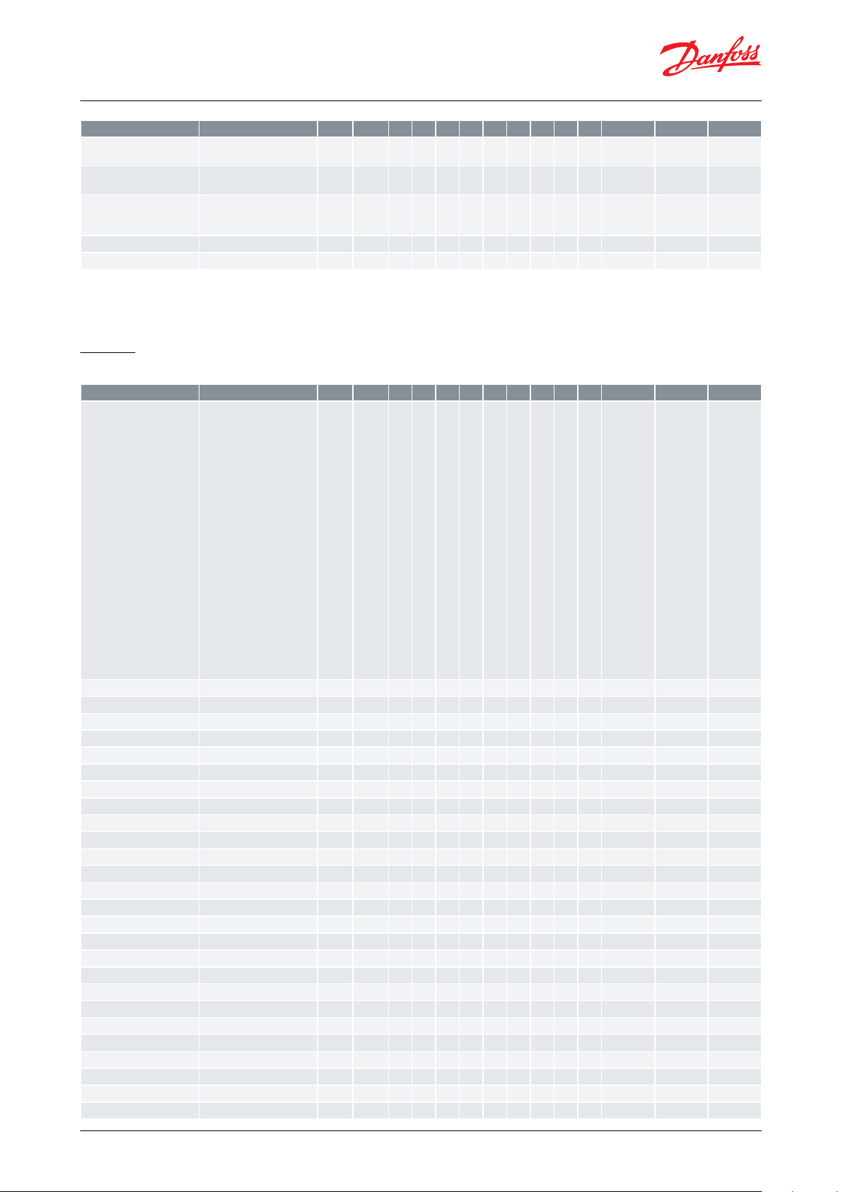
Function
Values
R-W
Code123456789Min. value
Max. value
Fact. value
Leak detection - Priority
0=Disabled, 3=Low, 2=Medium, 1=High
1-2
q36*********032
Humidity ctrl. - Priority
0=Disabled, 3=Low, 2=Medium, 1=High
1-2
q37*032
Food temp. sensor
1=Thermostat air, 2=Alarm
air, 3=S3 Air ON evap., 4=S6
Product temp.
1-2
(1)
q39*********142
LLSV - override
0=MAN OFF, 1=MAN ON
1-2
(2)
q45********010Dehumidier - override
0=MAN OFF, 1=MAN ON
1-2
(2)
q46*010
Function
Values
R-W
Code123456789Min. value
Max. value
Fact. value
Control state A
0=Normal ctrl., 1=Hold after defrost, 2=Min ON timer, 3=Min OFF timer,
4=Drip o, 10=Main switch
OFF, 11=Thermostat cutout, 12=Frost protection
S4, 14=Defrost, 15=Fan delay, 16=Forced closing,
17=Door open, 18=Melt
period, 19=Modulating
temp. control, 20=Emergency control, 23=Adaptive superheat control,
24=Start injection,
25=Manual control, 26=No
refrigerant selected,
29=Case cleaning,
30=Forced cooling,
31=Door open, 32=Powerup delay, 33=Air heating,
45=Shut down controller,
48=Adaptive liquid control,
51=Oil recovery
0-X
u00*********0510
S5 Evaporator A
0-X
u09*********-200.0 °C
200.0 °C
0.0 °C
DI1 Status
0=OFF, 1=ON
0-X
u10*******010
Defrost time A
0-X
u11*********0 min
900 min
0 min
S3 Air ON evap. A
0-X
u12*********-200.0 °C
200.0 °C
0.0 °C
Night condition
0=OFF, 1=ON
0-X
u13*********010
S4 Air OFF evap. A
0-X
u16*********-200.0 °C
200.0 °C
0.0 °C
Thermostat air temp. A
0-X
u17*********-200.0 °C
200.0 °C
0.0 °C
Thermostat run time A
0-X
u18*********0 min
999 min
0 min
S2 Gas outlet A
0-X
u20*********-200.0 °C
200.0 °C
0.0 °C
Superheat A
0-X
u21*********-200.0 °C
200.0 °C
0.0 °C
Superheat reference A
0-X
u22*********-200.0 °C
200.0 °C
0.0 °C
EEV opening A
0-X
u23*********0 %
100 %
0%
Pe Evap. pressure
0-X
u25*********-1.0 Bar
200.0 Bar
0.0 Bar
Te Evap. temp.
0-X
u26*********-200.0 °C
200.0 °C
0.0 °C
S6 product temp.
0-X
u36*******-200.0 °C
200.0 °C
0.0 °C
DI2 Status
0=OFF, 1=ON
0-X
u37*********010
Display readout 1
0-X
u56*********-200.0 °C
200.0 °C
0.0 °C
Alarm air temp. A
0-X
u57*********-200.0 °C
200.0 °C
0.0 °C
Compressor 1
0=OFF, 1=ON
0-X
u58****010Fan
0=OFF, 1=ON
0-X
u59*********010
Defrost A
0=OFF, 1=ON
0-X
u60********010Rail heat
0=OFF, 1=ON
0-X
u61*****010
Alarm relay
0=OFF, 1=ON
0-X
u62*******010
Light
0=OFF, 1=ON
0-X
u63********010Suction valve
0=OFF, 1=ON
0-X
u64*010
Compressor 2
0=OFF, 1=ON
0-X
u67*010
AK-CC55 Single Coil and AK-CC55 Single Coil UI
(1)
(1)
In order to change this parameter the regulation must be stopped via the parameter r12 Main switch = OFF.
In order to change this parameter the regulation must be stopped via the parameter r12 Main switch = OFF.
(2)
(2)
In order to change this parameter the parameter r12 Main switch must be set in position "SEr" allowing manual control of outputs.
In order to change this parameter the parameter r12 Main switch must be set in position "SEr" allowing manual control of outputs.
Service
Table 26: Service
© Danfoss | Climate Solutions | 2022.03 BC364229688105en-000201 | 51
Page 52

Function
Values
R-W
Code123456789Min. value
Max. value
Fact. value
S5 Evaporator B
0-X
u75********
-200.0 °C
200.0 °C
0.0 °C
S3 Air ON evap. B
0-X
u76**
-200.0 °C
200.0 °C
0.0 °C
Hot gas valve
0=OFF, 1=ON
0-X
u80*010
Blinds
0=OFF, 1=ON
0-X
u82*010
Defrost B
0=OFF, 1=ON
0-X
u83*010
Air heater
0=OFF, 1=ON
0-X
u84*010
Rail heat power
0-X
u85*********0 %
100 %
0%
Thermostat band
1=Band 1, 2=Band 2
0-X
u86*********121
DI3 Status
0=OFF, 1=ON
0-X
u87*********010
Thermostat cut-in temp.
0-X
u90*********-200.0 °C
200.0 °C
4.0 °C
Thermostat cut-out temp.
0-X
u91*********-200.0 °C
200.0 °C
2.0 °C
Adaptive defrost state
0=OFF, 1=Error, 2=Tuning,
3=OK, 4=Little ice, 5=Medium ice, 6=Heavy ice
0-X
U01*********060
Accumulated defrosts
0-X
U10*********0
32767
0
Accumulated skipped defrosts
0-X
U11*********0
32767
0
Alarm air temp. B
0-X
U34**
-200.0 °C
200.0 °C
0.0 °C
Display readout 2
0-X
U35********
-200.0 °C
200.0 °C
0.0 °C
Fan ECO
0=OFF, 1=ON
0-X
U37*010
Network status
0-X
U45*********0 %
100 %
0%
Drain valve
0=OFF, 1=ON
0-X
U55*010
Humidity sensor
0-X
U57*0 %
100 %
0%
Humidier
0=OFF, 1=ON
0-X
U58*010
Rail heat PWM
0-X
U59*********0 %
100 %
0%
Food temperature A
0-X
U72*********-200.0 °C
200.0 °C
0.0 °C
Defrost sensor temperature
A
0-X
U73*********-200.0 °C
200.0 °C
0.0 °C
Liquid line solenoid
0=OFF, 1=ON
0-X
U95********010Dehumidier
0=OFF, 1=ON
0-X
U96*010
AK-CC55 Single Coil and AK-CC55 Single Coil UI
© Danfoss | Climate Solutions | 2022.03 BC364229688105en-000201 | 52
Page 53
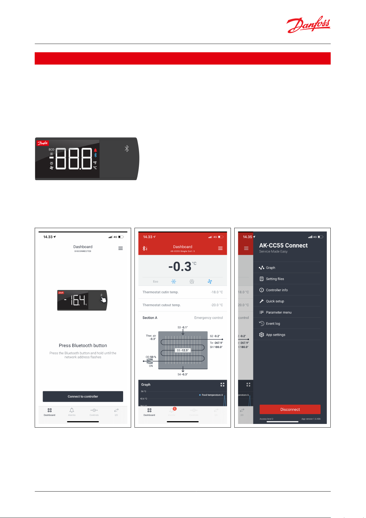
AK-CC55 Single Coil and AK-CC55 Single Coil UI
Operation via AK-UI55 Bluetooth
Access to parameters via Bluetooth and app
1.
App can be downloaded from App Store and Google Play.
◦ Name = AK-CC55 Connect
◦ Start the app.
2.
Click on the display’s Bluetooth button for 3 seconds.
◦ The Bluetooth light will then ash while display is showing the controller’s address.
3.
Connect to the controller from the app.
Figure 55: AK-UI55 Bluetooth
Display info:
• Loc
• The operation is locked and cannot be operated via Bluetooth.
• Unlock from the system manager.
Figure 56: Connect to controller Figure 57: Controller dashboard Figure 58: Set-up menu
The functions are described on Page 54 – Page 69.
© Danfoss | Climate Solutions | 2022.03 BC364229688105en-000201 | 53
Page 54
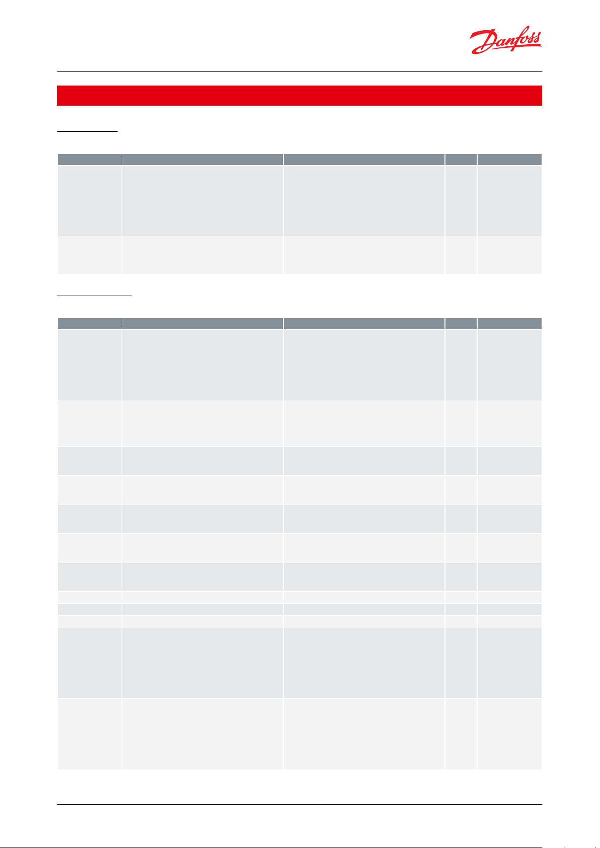
Function
Description
Values
Code
Short name
Main switch
Start / stop of refrigeration. With this setting refrigeration can be started, stopped or a manual override of
the outputs can be allowed. (For manual control the
value is set at -1). Then the outputs can be force controlled. Start / stop of refrigeration can also be accomplished with the external switch function connected
to a DI input.Stopped control will give a ”Main switch
OFF" alarm.
-1=Manual, 0=Stop, 1=Start
r12
r12 Main switch
Delay of outputs at
power-up
Delay of output signal after start-up After start-up or
a power failure the controller’s functions can be delayed so that overloading of the electricity supply
network is avoided. Here you can set the time delay.
o01
o01 DelayOfOutp.
Function
Description
Values
Code
Short name
Main switch
Start / stop of refrigeration. With this setting refrigeration can be started, stopped or a manual override of
the outputs can be allowed. (For manual control the
value is set at -1). Then the outputs can be force controlled. Start / stop of refrigeration can also be accomplished with the external switch function connected
to a DI input.Stopped control will give a ”Main switch
OFF" alarm.
-1=Manual, 0=Stop, 1=Start
r12
r12 Main switch
Application mode
Selection of application The controller covers several
applications for control of a refrigerated case. Here
you set which of the possible applications is required.This menu can only be set when regulation is
stopped, i.e. “r12 Main Switch” is set to 0.
1=1. Comp/Alarm/Light, 2=2. Comp/Rail/Light, 3=3.
Comp/Alarm/Rail, 4=4. Alarm/Rail/Light, 5=5. Hot gas
remote, 6=6. Dual with 1 evap., 7=7. Dual with 2
evap., 8=8. Cold room, 9=9. Custom
o61
o61 Appl. mode
DO2 Conguration
Select the function of the digital output
0=None, 1=Fans, 2=Fan ECO, 3=Defrost, 4=Rail heat,
5=Alarm, 6=Light, 7=Blinds, 8=Compressor/LLSV,
9=Compressor 2, 10=Air heater
q02
q02 DO2 Cong.
DO3 Conguration
Select the function of the digital output
0=None, 1=Fans, 2=Fan ECO, 3=Defrost, 4=Rail heat,
5=Alarm, 6=Light, 7=Blinds, 8=Compressor/LLSV,
9=Compressor 2, 10=Air heater
q03
q03 DO3 Cong.
DO4 Conguration
Select the function of the digital output
0=None, 1=Fans, 2=Fan ECO, 3=Defrost, 4=Rail heat,
5=Alarm, 6=Light, 7=Blinds, 8=Compressor/LLSV,
9=Compressor 2, 10=Air heater
q04
q04 DO4 Cong.
DO5 Conguration
Select the function of the digital output
0=None, 1=Fans, 2=Fan ECO, 3=Defrost, 4=Rail heat,
5=Alarm, 6=Light, 7=Blinds, 8=Compressor/LLSV,
9=Compressor 2, 10=Air heater
q05
q05 DO5 Cong.
DO6 Conguration
Select the function of the digital output
0=None, 1=Fans, 2=Fan ECO, 3=Defrost, 4=Rail heat,
5=Alarm, 6=Light, 7=Blinds, 8=Compressor/LLSV,
9=Compressor 2, 10=Air heater
q06
q06 DO6 Cong.
AO1 Conguration
Select the function of the analogue output
0=None, 1=Rail heat PWM, 2=Valve driver
q09
q09 AO1 Cong.
AO1 Min. voltage
Minimum voltage signal of the analogue output
o27
o27 AO1 Min volt
AO1 Max. voltage
Maximum voltage signal of the analogue output
o28
o28 AO1 Max volt
DI1 Conguration
Select the function of the digital input
0=None, 1=DI status, 2=Door function, 3=Door alarm,
4=Defrost start, 5=Main switch, 6=Night setback,
7=Thermostat band, 8=Alarm at closed, 9=Alarm at
open, 10=Case cleaning, 11=Forced cooling,
12=Open blinds, 14=Forced closing, 15=Shutdown,
16=Light control, 20=Leak detection, 21=Adaptive
liquid control, 22=Valve driver, 23=Fan alarm,
29=Door fan stop, 30=Oil recovery
o02
o02 DI1 Cong.
DI2 Conguration
Select the function of the digital input
0=None, 1=DI status, 2=Door function, 3=Door alarm,
4=Defrost start, 5=Main switch, 6=Night setback,
7=Thermostat band, 8=Alarm at closed, 9=Alarm at
open, 10=Case cleaning, 11=Forced cooling,
12=Open blinds, 13=Coordinated defrost, 14=Forced
closing, 15=Shutdown, 16=Light control, 20=Leak detection, 21=Adaptive liquid control, 22=Valve driver,
23=Fan alarm, 29=Door fan stop, 30=Oil recovery
o37
o37 DI2 Cong.
AK-CC55 Single Coil and AK-CC55 Single Coil UI
AK-CC55 connect menu (SW ver. 1.7x)
Start / Stop
Table 27: Start/Stop
Conguration
Table 28: Conguration
© Danfoss | Climate Solutions | 2022.03 BC364229688105en-000201 | 54
Page 55

Function
Description
Values
Code
Short name
DI3 Conguration
Select the function of the digital input
0=None, 1=DI status, 2=Door function, 3=Door alarm,
4=Defrost start, 5=Main switch, 6=Night setback,
7=Thermostat band, 8=Alarm at closed, 9=Alarm at
open, 10=Case cleaning, 11=Forced cooling,
12=Open blinds, 13=Coordinated defrost, 14=Forced
closing, 15=Shutdown, 16=Light control, 20=Leak detection, 21=Adaptive liquid control, 29=Door fan
stop, 30=Oil recovery
o84
o84 DI3 Cong
Refrigerant
Select the type of refrigerant. If the required refrigerant is not part of the list, the user dened option can
be used. Please contact Danfoss for detailed information
WARNING:
Wrong selection of refrigerant may cause damage to
the system.
0=Not seleted, 6=R13, 7=R13b1, 2=R22, 8=R23,
14=R32, 11=R114, 3=R134a, 12=R142b, 24=R170,
15=R227, 25=R290, 16=R401A, 18=R402A, 19=R404A,
21=R407A, 22=R407B, 20=R407C, 37=R407F,
49=R407H, 23=R410A, 32=R413A, 30=R417A,
31=R422A, 33=R422D, 34=R427A, 35=R438A,
40=R448A, 41=R449A, 48=R449B, 43=R450A,
44=R452B, 45=R454B, 9=R500, 4=R502, 10=R503,
17=R507, 36=R513A, 26=R600, 27=R600a, 5=R717,
28=R744, 46=R1233zdE, 38=R1234ze, 39=R1234yf,
47=R1234zeZ, 29=R1270, 42=R452A, 1=User dened
display, 13=User dened
o30
o30 Refrigerant
Refrigerant factor K1
Refrigerant factor for a custom refrigerant - please
contact Danfoss for detailed information
P83
P83 RfgFac.K1
Refrigerant factor K2
Refrigerant factor for a custom refrigerant - please
contact Danfoss for detailed information
P84
P84 RfgFac.K2
Refrigerant factor K3
Refrigerant factor for a custom refrigerant - please
contact Danfoss for detailed information
P85
P85 RfgFac.K3
Refrigerant factor A1
Refrigerant factor for a custom refrigerant - please
contact Danfoss for detailed information
x65
--- Rfg.Fac.A1
Refrigerant factor A2
Refrigerant factor for a custom refrigerant - please
contact Danfoss for detailed information
x66
--- Rfg.Fac.A2
Refrigerant factor A3
Refrigerant factor for a custom refrigerant - please
contact Danfoss for detailed information
x67
--- Rfg.Fac.A3
Pe Min range
Minimum measuring range for sensor
o20
o20 MinTransPres
Pe Max range
Maximum measuring range for sensor
o21
o21 MaxTransPres
Temperature sensor
type
Sensor type for S3, S4 and S5. Normally a Pt 1000 sensor with great signal accuracy is used. But you can also use a sensor with another signal accuracy. That
could e.g. be a PTC sensor (1000 ohm at 25 °C). All the
mounted sensors S3-S5 must be of the same type.
0=Pt 1000, 1=PTC 1000, 2=NTC 5k, 3=NTC 10k,
4=User-dened
o06
o06 SensorCong
Sensor point 1 Temp.
The temperature value for the user-dened temperature sensor in the reference point
X20
--- SP1 Temp.
Sensor point 1 kohm
The resistance value in kohm for the user-dened
temperature sensor in the reference point
X21
--- SP1 kohm
Sensor point 1 ohm
The resistance value in ohm for the user-dened temperature sensor in the reference point
X22
--- SP1 Ohm
Sensor point 2 Temp.
The temperature value for the user-dened temperature sensor in the reference point
X23
--- SP2 Temp.
Sensor point 2 kohm
The resistance value in kohm for the user-dened
temperature sensor in the reference point
X24
--- SP2 kohm
Sensor point 2 ohm
The resistance value in ohm for the user-dened temperature sensor in the reference point
X25
--- SP2 Ohm
Sensor point 3 Temp.
The temperature value for the user-dened temperature sensor in the reference point
X26
--- SP3 Temp.
Sensor point 3 kohm
The resistance value in kohm for the user-dened
temperature sensor in the reference point
X27
--- SP3 kohm
Sensor point 3 ohm
The resistance value in ohm for the user-dened temperature sensor in the reference point
X28
--- SP3 Ohm
Food type
When changing the food type the controller will automatically adapt temperature setpoints and alarm limits according to the selected food type. Please be
aware that the setting will revert to "None" after having been changed.
0=None, 1=Vegetables, 2=Dairy, 3=Meat and sh,
4=Frozen food, 5=Ice cream
r89
r89 Food type
Food temp. sensor
Select the temperature to be used for the food temperature representation
1=Thermostat air, 2=Alarm air, 3=S3 Air ON evap.,
4=S6 Product temp.
q39
q39 Food sensor
Defrost method
Select method of defrost
0=None, 1=Electrical, 2=Hot gas, 4=Air/Ocycle
d01
d01 Def. method
Defrost stop method
Here you dene whether a defrost cycle is to be stopped by time or by a temperature sensor
0=Time, 1=S5 sensor, 2=S4 sensor, 3=S5A and S5B
d10
d10 DefStopSens.
AK-CC55 Single Coil and AK-CC55 Single Coil UI
© Danfoss | Climate Solutions | 2022.03 BC364229688105en-000201 | 55
Page 56

Function
Description
Values
Code
Short name
Defrost stop limit A
When the selected defrost stop sensor reaches the set
limit, the defrost cycle is terminated
d02
d02 Def.StopTemp
Network address
Network address of the controller
o03
o03 Unit addr.
Service pin
If the controller is built into a LonWorks network with
data communication, it must have an address, and
the system manager must know this address.The address is sent to the system manager when the menu
is set in pos. ON.
IMPORTANT:
Before you set o04, you MUST set the application
mode of the controller (The function is not used
when the data communication is MODBUS)
0=OFF, 1=ON
o04
o04 Service pin
Function
Description
Values
Code
Short name
Control state A
Readout of the actual control state of the controller
0=Normal ctrl., 1=Hold after defrost, 2=Min ON timer,
3=Min OFF timer, 4=Drip o, 10=Main switch OFF,
11=Thermostat cut-out, 12=Frost protection S4,
14=Defrost, 15=Fan delay, 16=Forced closing,
17=Door open, 18=Melt period, 19=Modulating
temp. control, 20=Emergency control, 23=Adaptive
superheat control, 24=Start injection, 25=Manual
control, 26=No refrigerant selected, 29=Case cleaning, 30=Forced cooling, 31=Door open, 32=Power-up
delay, 33=Air heating, 45=Shut down controller,
48=Adaptive liquid control, 51=Oil recovery
u00
u00 Ctrl. state
Thermostat air
temp. A
Thermostat temperature
u17
u17 Ther. air
Food temperature A
Readout of food temperature
U72
U72 Food temp.
S3 Air ON evap. A
Actual sensor value
u12
u12 S3 air temp.
S3 Air ON evap. B
Actual sensor value
u76
u76 S3 airtemp B
S4 Air OFF evap. A
Actual sensor value
u16
u16 S4 air temp.
Night condition
Status of the day/night operation (night operation:
on/o)
0=OFF, 1=ON
u13
u13 Night Cond.
Thermostat cut-in
temp.
Readout of the actual cut-in value for the thermostat
u90
u90 Cutin temp.
Thermostat cut-out
temp.
Readout of the actual cut-out value for the thermostat
u91
u91 Cutout temp.
Thermostat run time
A
Read the ongoing cut-in time for the thermostat or
the duration of the last completed cut-in
u18
u18 Ther runtime
Thermostat band
Readout of which thermostat is used for regulation:
1= Thermostat band, 12= Thermostat band 2
1=Band 1, 2=Band 2
u86
u86 Ther. band
Air heater
Actual status of output function
0=OFF, 1=ON
u84
u84 Heat relay
Thermostat mode
Here it is dened how the thermostat is to be operated. Either as an ordinary ON/OFF thermostat or as a
modulating thermostat. When operation is ”modulating” the valve will limit the ow of refrigerant so that
the temperature variation will be less than for the
ON/OFF thermostat. The thermostat dierential (r01)
must not be set lower than 2K for "modulating". In a
decentralised plant you must select the ON/OFF thermostat setting.
1=ON/OFF, 2=Modulating
r14
r14 Therm. mode
Cut-out 1
Setpoint. The thermostat’s cut-out value when the
given thermostat band is in use
r00
r00 Cutout
Cut-out 2
Setpoint. The thermostat’s cut-out value when the
given thermostat band is in use
r21
r21 Cutout 2
Dierential 1
When the temperature is higher than the set cut-out
+ the set dierential, the compressor relay will be cutin. It will cut-out again when the temperature comes
down to the set cut-out limit
r01
r01 Dierential
Dierential 2
When the temperature is higher than the set cut-out
+ the set dierential, the compressor relay will be cutin. It will cut-out again when the temperature comes
down to the set cut-out limit
r93
r93 Di Th2
AK-CC55 Single Coil and AK-CC55 Single Coil UI
Thermostat control
Table 29: Thermostat control
© Danfoss | Climate Solutions | 2022.03 BC364229688105en-000201 | 56
Page 57

Function
Description
Values
Code
Short name
Max cut-out limit
Setpoint limitation - The controller’s setting range for
the thermostat setpoint may be narrowed down, so
that too high or too low values are not set accidentally - with resulting damages. To avoid a too high setting of the setpoint, the max. allowable reference value may be lowered
r02
r02 Max cutout
Min cut-out limit
Setpoint limitation - The controller’s setting range for
the thermostat setpoint may be narrowed down, so
that too high or too low values are not set accidentally - with resulting damages. To avoid a too low setting
of the setpoint, the min. allowable reference value
may be increased
r03
r03 Min cutout
Thermostat sensor
S4 %
Selection of thermostat sensor. Here you dene the
sensor that the thermostat is to use for its control
function. S3, S4, or a combination of them. With the
setting 0%, only S3 is used. With 100%, only S4.
r15
r15 Ther. S4 %
Thermostat sensor
S4 % night
Selection of thermostat sensor S4% during night operation with night blinds. Here you dene the sensor
that the thermostat is to use for its control function.
S3, S4, or a combination of them. With the setting 0%,
only S3 is used. With 100%, only S4.
r61
r61 Ther.S4% Ngt
Night oset
Night setback value.The thermostat’s reference will
be the setpoint plus this value when the controller
changes over to night operation.
r13
r13 Night oset
S4 frost protection
Frost protection on S4 air temperature. If the S4 temperature sensor measure a temperature lower than
the set limit, refrigeration will be stopped in order to
protect products from ice formation. Refrigeration
will start again when the S4 temperature has risen 2K
above the set limit
r98
r98 S4 Min Lim
Air heater neutral
zone
Heat function. Set the width of the Neutral Zone for
changeover from cooling to heating
r62
r62 Heat NZ
Air heater start delay
Time delay on transition from refrigeration phase to
heating phase (there is no time delay on transition
from heating phase to refrigeration)
r63
r63 HeatStartDel
Melt interval
Melt function. Only for control of MT cases/rooms (-5
– +10 °C). The function ensures that the evaporator
will not be blocked by ice crystals. Here you set how
often the function is to stop the refrigeration and
hence transform the ice crystals to water.
r16
r16 MeltInterval
Melt period
Melt period. Here you set how long an ongoing melt
function is to last
r17
r17 Melt period
Function
Description
Values
Code
Short name
Alarm status
Actual alarm status
0=OFF, 1=ON
x16
--- Sum alarm
Control state A
Readout of the actual control state of the controller
0=Normal ctrl., 1=Hold after defrost, 2=Min ON timer,
3=Min OFF timer, 4=Drip o, 10=Main switch OFF,
11=Thermostat cut-out, 12=Frost protection S4,
14=Defrost, 15=Fan delay, 16=Forced closing,
17=Door open, 18=Melt period, 19=Modulating
temp. control, 20=Emergency control, 23=Adaptive
superheat control, 24=Start injection, 25=Manual
control, 26=No refrigerant selected, 29=Case cleaning, 30=Forced cooling, 31=Door open, 32=Power-up
delay, 33=Air heating, 45=Shut down controller,
48=Adaptive liquid control, 51=Oil recovery
u00
u00 Ctrl. state
Alarm air temp. A
Measured temperature for alarm thermostat
u57
u57 Alarm air
Alarm air temp. B
Measured temperature for alarm thermostat
U34
U34 Alarm air B
High alarm limit
Readout of actual high alarm limit for the temperature monitoring
y10
--- High al. lim
Low alarm limit
Readout of actual low alarm limit for the temperature
monitoring
y11
--- Low al. lim
S3 Air ON evap. A
Actual sensor value
u12
u12 S3 air temp.
S3 Air ON evap. B
Actual sensor value
u76
u76 S3 airtemp B
S4 Air OFF evap. A
Actual sensor value
u16
u16 S4 air temp.
S6 product temp.
Actual sensor value
u36
u36 S6 temp.
Reset alarms
Command for resetting all alarms, unless they are still
active
0=OFF, 1=ON
x15
--- Reset alarm
AK-CC55 Single Coil and AK-CC55 Single Coil UI
Alarm limits and delays
Table 30: Alarm limits and delays
© Danfoss | Climate Solutions | 2022.03 BC364229688105en-000201 | 57
Page 58

Function
Description
Values
Code
Short name
Alarm sensor S4% A
Signal to the alarm thermostat Here you have to dene the ratio between the sensors which the alarm
thermostat has to use. S3, S4 or a combination of the
two. With setting 0% only S3 is used. With 100% only
S4 is used
A36
A36 Alarm S4 %
High alarm limit 1
Upper alarm limit. The limit value is set in absolute
value. The limit value will be raised with the night o-
set during night operation.
A13
A13 HighLim Air
Low alarm limit 1
Lower alarm limit. The limit value is set in absolute
value
A14
A14 LowLim Air
High alarm limit 2
Upper alarm limit. The limit value is set in absolute
value. The limit value will be raised with the night o-
set during night operation.
A20
A20 HighLim2 Air
Low alarm limit 2
Lower alarm limit. The limit value is set in absolute
value
A21
A21 LowLim2 Air
Alarm delay A
Alarm delay (short alarm delay on air temperature). If
the upper or the lower alarm limit values are exceeded, a timer function will commence. The alarm will
not become active until the set time delay has been
passed. The time delay is set in minutes
A03
A03 Alarm delay
Alarm delay pull
down A
Alarm delay at tempeature pull down conditions
(long alarm delay). This time delay is used during
start-up, during defrost and immediately after a defrost. There will be a change-over to the normal time
delay when the temperature has dropped below the
set upper alarm limit.
A12
A12 Pulldown del
Alarm delay B
Alarm delay (short alarm delay on air temperature). If
the upper or the lower alarm limit values are exceeded, a timer function will commence. The alarm will
not become active until the set time delay has been
passed. The time delay is set in minutes
A53
A53 Al.Del.S3 B
Use product sensor
S6
Select whether a separate S6 product sensor must be
used for monitoring of the product temperature
0=No, 1=Yes
a01
a01 S6 function
S6 High alarm limit 1
Upper alarm limit for S6 product temperature. The
limit is raised with the nightoset during night operation.
A22
A22 HighLim1 S6
S6 Low alarm limit 1
Lower alarm limit for S6 product temperature
A23
A23 LowLim1 S6
S6 High alarm limit 2
Upper alarm limit for S6 product temperature. The
limit is raised with the nightoset during night operation.
A24
A24 HighLim2 S6
S6 Low alarm limit 2
Lower alarm limit for S6 product temperature
A25
A25 LowLim2 S6
S6 alarm delay
S6 temperature alarm delay. The alarm is activated if
one of the relevant alarm limits is exceeded. The time
delay is set in minutes. (Alarms will not activate when
the setting is set to the maximum value.)
A26
A26 AL.Delay S6
S6 alarm pull down
delay
Time delay on S6 (product sensor) at temperature pull
down conditions (long alarm delay). This time delay is
used for start-up, during defrosting, immediately after
a defrost and after an appliance cleaning. A change is
carried out to standard time delay when the temperature has reached below the set upper alarm limit.
A52
A52 PullD del.S6
Door open alarm
delay
Time delay for door alarm
A04
A04 DoorOpen del
Door restart inj. delay
Start of refrigeration when the door is open. If the
door has been left open, refrigeration will be started
after the set time.
o89
o89 DoorInjStart
Alarm delay DI 1
Time delay for digital input alarm
A27
A27 Al.Delay DI1
Alarm delay DI 2
Time delay for digital input alarm
A28
A28 Al.Delay DI2
AK-CC55 Single Coil and AK-CC55 Single Coil UI
© Danfoss | Climate Solutions | 2022.03 BC364229688105en-000201 | 58
Page 59

Function
Description
Values
Code
Short name
Control state A
Readout of the actual control state of the controller
0=Normal ctrl., 1=Hold after defrost, 2=Min ON timer,
3=Min OFF timer, 4=Drip o, 10=Main switch OFF,
11=Thermostat cut-out, 12=Frost protection S4,
14=Defrost, 15=Fan delay, 16=Forced closing,
17=Door open, 18=Melt period, 19=Modulating
temp. control, 20=Emergency control, 23=Adaptive
superheat control, 24=Start injection, 25=Manual
control, 26=No refrigerant selected, 29=Case cleaning, 30=Forced cooling, 31=Door open, 32=Power-up
delay, 33=Air heating, 45=Shut down controller,
48=Adaptive liquid control, 51=Oil recovery
u00
u00 Ctrl. state
Humidity sensor
U57
U57 RH level %
Humidier
Actual status of output function
0=OFF, 1=ON
U58
U58 Humidier
Dehumidier
Actual status of output function
0=OFF, 1=ON
U96
U96 Dehumidier
Humidity control
Select the type of humidity control
0=None, 1=Humidier, 2=Dehumidier
h31
h31 RH function
Humidity cut-in
Setpoint for the humidity control. If the relative humidity goes below the setpoint, the humidier is started
h23
h23 RH Cutin SP
Humidity dierential
Dierential for stopping humidier. Humidication is
stopped when the humidity has increased with the
set dierntial above the setpoint
h24
h24 RH Di.
Humidity high alarm
limit
High alarm limit for relative humidity
h25
h25 RH HighLimAl
Humidity low alarm
limit
Low alarm limit for relative humidity
h26
h26 RH LowLimAl
Humidity alarm delay
Delay of high and low humidity alarms
h27
h27 RH Al. delay
Humidity sensor Min signal
h29
h29 RH Min Value
Humidity sensor Max signal
h30
h30 RH Max Value
Humidity ctrl. at defrost
Select how to control humidity during defrost:No: Humidity control is stopped during defrostYes: Normal
humidity control is running during defrost
0=No, 1=Yes
h28
h28 RH CtrlAtDef
Humidity max.
temp.
Maximum limit for thermostat air temperature in order for humidity control to run (frost limit)
h32
h32 RH Max temp.
Humidity min. temp.
Minimum limit for thermostat air temperature in order for humidity control to run (frost limit)
h33
h33 RH Min temp.
Function
Description
Values
Code
Short name
Control state A
Readout of the actual control state of the controller
0=Normal ctrl., 1=Hold after defrost, 2=Min ON timer,
3=Min OFF timer, 4=Drip o, 10=Main switch OFF,
11=Thermostat cut-out, 12=Frost protection S4,
14=Defrost, 15=Fan delay, 16=Forced closing,
17=Door open, 18=Melt period, 19=Modulating
temp. control, 20=Emergency control, 23=Adaptive
superheat control, 24=Start injection, 25=Manual
control, 26=No refrigerant selected, 29=Case cleaning, 30=Forced cooling, 31=Door open, 32=Power-up
delay, 33=Air heating, 45=Shut down controller,
48=Adaptive liquid control, 51=Oil recovery
u00
u00 Ctrl. state
Thermostat air
temp. A
Thermostat temperature
u17
u17 Ther. air
S3 Air ON evap. A
Actual sensor value
u12
u12 S3 air temp.
S3 Air ON evap. B
Actual sensor value
u76
u76 S3 airtemp B
S4 Air OFF evap. A
Actual sensor value
u16
u16 S4 air temp.
EEV opening A
Actual status of output function
u23
u23 EEV OD %
Liquid line solenoid
Actual status of output function
0=OFF, 1=ON
U95
U95 LLSV
Pe Evap. pressure
Actual sensor signal
u25
u25 EvapPress Pe
Te Evap. temp.
Temperature converted from pressure
u26
u26 EvapTemp Te
S2 Gas outlet A
Actual sensor value
u20
u20 S2 temp.
Superheat A
Readout of actual superheat at the outlet of the evaporator
u21
u21 Superheat
AK-CC55 Single Coil and AK-CC55 Single Coil UI
Humidity control
Table 31: Humidity control
Injection control
Table 32: Injection control
© Danfoss | Climate Solutions | 2022.03 BC364229688105en-000201 | 59
Page 60

Function
Description
Values
Code
Short name
Superheat reference
A
Readout of the actual superheat reference
u22
u22 SuperheatRef
Min. superheat limit
Min. value for the superheat reference
n10
n10 Min SH
Max. superheat limit
Max. value for the superheat reference
n09
n09 Max SH
MOP temperature
MOP temperature. The valve opening degree is reduced until the evaporating temperature reaches the
set MOP limit. If no MOP function is required, select
the highest value that corresponds to OFF
n11
n11 MOP temp.
AKV Period time
Period time for the pulse width modulation
n13
n13 AKV Period
Min. superheat liquid ctrl A
Min. value for the superheat reference during adaptive liquid control
P87
P87 SH Min Liq.
Max. superheat liquid ctrl. A
Max. value for the superheat reference during adaptive liquid control
P86
P86 SH Max Liq.
LLSV closing delay
Closing delay for liquid line solenoid valve
P92
P92 LLSV OFF del
Oil recovery mode
Select how oil recovery is to be handled:
0 = None
1 = Adaptive liquid control with normal fan control
2 = Adaptive liquid control with fans OFF
3 = Fixed valve opening degree with normal fan control
4 = Fixed valve opening degree with fans OFF
WARNING:
In option 3 and 4, superheat control is omitted and it
is the responsibility of the user to safeguard the compressors.
0=None, 1=ALC and Fan ctrl, 2=ALC and Fan OFF,
3=Fixed OD and Fan ctrl, 4=Fixed OD and Fan OFF
x30
--- Oil rec mode
Max oil recovery
time
Maximum time for an oil recovery cycle. If an oil recovery cycle lasts longer than the set time, the oil recovery cycle will be terminated
x31
--- Oil rec max
Oil recovery OD
Fixed valve opening degree during oil recoveryWarning: Superheat control is omitted and it is the responsibility of the user to safeguard the compressors
x32
--- Oil rec OD%
Function
Description
Values
Code
Short name
Control state A
Readout of the actual control state of the controller
0=Normal ctrl., 1=Hold after defrost, 2=Min ON timer,
3=Min OFF timer, 4=Drip o, 10=Main switch OFF,
11=Thermostat cut-out, 12=Frost protection S4,
14=Defrost, 15=Fan delay, 16=Forced closing,
17=Door open, 18=Melt period, 19=Modulating
temp. control, 20=Emergency control, 23=Adaptive
superheat control, 24=Start injection, 25=Manual
control, 26=No refrigerant selected, 29=Case cleaning, 30=Forced cooling, 31=Door open, 32=Power-up
delay, 33=Air heating, 45=Shut down controller,
48=Adaptive liquid control, 51=Oil recovery
u00
u00 Ctrl. state
Defrost sensor temperature A
Actual temperature of selected defrost stop sensor
U73
U73 Def.StopTemp
S5 Evaporator A
Actual sensor value
u09
u09 S5 temp.
S5 Evaporator B
Actual sensor value
u75
u75 S5 temp. B
Defrost A
Actual status of output function
0=OFF, 1=ON
u60
u60 Def. relay
Defrost B
Actual status of output function
0=OFF, 1=ON
u83
u83 Def. relay B
Defrost time A
Read the duration of the ongoing defrost or the duration of the last completed defrost.
u11
u11 Defrost time
Adaptive defrost
state
Actual state of the adaptive defrost function
0=OFF, 1=Error, 2=Tuning, 3=OK, 4=Little ice, 5=Medium ice, 6=Heavy ice
U01
U01 AD state
Accumulated defrosts
Number of defrosts carried out since the initial power-up or since the resetting of the function
U10
U10 Acc.defrost
Accumulated skipped defrosts
Number of defrosts skipped since the initial power-up
or since the resetting of the function
U11
U11 Acc.def.skip
Tc average temp.
Average value of the condensing temperature signal
distributed via the system manager to the case controllers that are using adaptive defrost. At transcritical
CO2 sites the receiver pressure is distributed to the
case controllers. The function needs to be set up in
the system manager.
x02
--- Tc temp. Ave
Start defrost
Command for starting a defrost
0=OFF, 1=ON
x09
--- Def. Start
Stop defrost
Command for stopping an ongoing defrost cycle
0=OFF, 1=ON
x10
--- Def. Stop
AK-CC55 Single Coil and AK-CC55 Single Coil UI
Defrost control
Table 33: Defrost control
© Danfoss | Climate Solutions | 2022.03 BC364229688105en-000201 | 60
Page 61

Function
Description
Values
Code
Short name
Defrost method
Select method of defrost
0=None, 1=Electrical, 2=Hot gas, 4=Air/Ocycle
d01
d01 Def. method
Defrost stop method
Here you dene whether a defrost cycle is to be stopped by time or by a temperature sensor
0=Time, 1=S5 sensor, 2=S4 sensor, 3=S5A and S5B
d10
d10 DefStopSens.
Defrost stop limit 1
When the selected defrost stop sensor reaches the set
limit, the defrost cycle is terminated
d02
d02 Def.StopTemp
Defrost stop limit 2
Defrost stop temperature limit when thermostat
band 2 is in operation.When the selected defrost stop
sensor reaches the set limit, the defrost cycle is terminated
d28
d28 DefStopTemp2
Min. defrost time
Minimum duration of a defrost cycle. The defrost cycle will as a minimum run for the set minimum defrost time once it is started
d24
d24 Min Def.time
Max. defrost time 1
Max duration of a defrost cycle. The setting is also
used as a safety time if the defrost is stopped on temperature. If the selected defrost stop sensor does not
reach the set defrost stop temperature limit within
the set time, the defrost will be stopped anyway.
d04
d04 Max Def.time
Max. defrost time 2
Max duration of a defrost cycle when thermostat
band 2 is in operation. The setting is also used as a
safety time if the defrost is stopped on temperature. If
the selected defrost stop sensor does not reach the
set defrost stop temperature limit within the set time,
the defrost will be stopped anyway.
d29
d29 MaxDefTime2
Defrost start interval
The function is zeroset and will start the timer function at each defrost start. When the time has expired
the function will start a defrost. The function is used
as a simple defrost start, or it may be used as a safeguard if the normal signal fails to appear. If master/
slave defrost without clock function or without data
communication is used, the interval time will be used
as max. time between defrosts. If a defrost start via
data communcation does not take place, the interval
time will be used as max. time between defrosts.When there is defrost with clock function or data communication, the interval time must be set for a
somewhat longer period of time than the planned
one. In connection with power failure the interval
time will be maintained, and when the power returns
the interval time will continue from the maintained
value. he interval time is not active when set to 0
d03
d03 Def.Interval
Time staggering
power-up
Time staggering for defrost cut-ins during start-up
The function is only relevant if you have several refrigeration appliances or groups where you want the defrost to be staggered in relation to one another. The
function is furthermore only relevant if you have
chosen defrost with interval start. The function delays
the interval time by the set number of minutes, but it
only does it once, and this at the very rst defrost taking place when voltage is connected to the controller.
The function will be active after each and every power failure.
d05
d05 Time stagg.
Max. thermostat run
time
Defrost on demand. Aggregate refrigeration time set
here is the refrigeration time allowed without defrosts. If the time is passed, a defrost will be started.
With setting = 0 the function is not in use.
d18
d18 MaxTherRunT.
Pump down delay
Set the time where the evaporator is emptied of refrigerant prior to the actual defrost cycle
d16
d16 Pump dwn del
Hot gas injection
delay
Delay before opening hot gas valve
d23
d23 HotGasInjDel
Drip o time
Here you set the time that is to elapse from a defrost
and until the compressor is to start again. (The time
when water drips o the evaporator).
d06
d06 DripO time
Max. hold time
Max. standby time after coordinated defrost. When a
controller has completed a defrost it will wait for a
signal tellingthat the refrigeration may be resumed. If
this signal fails to appear for one reason or another,
the controller itself will start the refrigeration when
the standby time has elapsed.
o16
o16 MaxHoldTime
Drain delay
Drain delay (only in connection with hot gas). Set the
time where the evaporator is emptied of condensed
refrigerant after the defrost.
d17
d17 Drain delay
AK-CC55 Single Coil and AK-CC55 Single Coil UI
© Danfoss | Climate Solutions | 2022.03 BC364229688105en-000201 | 61
Page 62

Function
Description
Values
Code
Short name
Fan control during
defrost
Fan operation during defrost Here you can set how
the fan is to operate during defrost.
0: Stopped (runs during pump down)
1: Running (stopped during "fan delay)
2: Running during pump down and defrost. After that
stopped
3: Running during pump down and defrost until defrost stop sensor reaches fan stop temperature limit
0=OFF, 1=ON, 2=OFF at drip, 3=OFF at high temp
d09
d09 FanDuringDef
Fan stop temperature
If the fan control during defrost has been set up for it,
the fans can be stopped during the defrost if the defrost sensor exceeds the set temperature limit
d41
d41 Def Fan Stop
Fan start delay
Delay of fan start after defrost. Here you set the time
that is to elapse from compressor start after a defrost
and until the fan may start again. (The time when remaining water is transformed into ice on the evaporator).
d07
d07 FanStartDel
Fan start temperature
Temperature limit for starting the fans after a defrost.
When the measured S5 evaporator temperature is
getting below the set limit, the fans are started
d08
d08 FanStartTemp
Rail heat during defrost
Dene how rail heat is controlled during defrost
0: Rail heat is OFF all the time
1: Rail heat is ON all the time
2: Normal rail heat control
0=OFF, 1=ON, 2=Normal control
d27
d27 Railh.at def
Display delay after
defrost
Set the maximum time the display should show the
defrost code "-d-" after a defrost. The normal temperature readout is normally started when the temperature in the case is OK again or if a high temperature
alarm is raised.
d40
d40 Disp. d del.
Adaptive defrost
mode
Adaptive defrost is used to skip planned defrost cycles if they are not needed or in odrer to start an extra
defrost when required
0: Not used
1: Monitors the evaporator and triggers an alarm in
the case of icing up.
2: Scheduled defrosts during day time can be skipped.
3: Scheduled defrosts during day and night time can
be skipped.
4: All schedules are carried out + extra if it is registered that this is required. (Temporary setting to 0FF
will reset the recorded values.)
0=OFF, 1=Monitoring, 2=Skip day, 3=Skip day/night,
4=Full adaptive
d21
d21 AD mode
Function
Description
Values
Code
Short name
Defrost schedule
0=No, 1=Yes
t00
t00 Def.Schedule
Def. start 1 - Hours
Time in hours for start of defrost
t01
t01 Def. 1 hr.
Def. start 1 - Minutes
Time in minutes for when defrost cycle is to be started
t11
t11 Def. 1 min.
Def. start 2 - Hours
Time in hours for start of defrost
t02
t02 Def. 2 hr.
Def. start 2 - Minutes
Time in minutes for when defrost cycle is to be started
t12
t12 Def. 2 min.
Def. start 3 - Hours
Time in hours for start of defrost
t03
t03 Def. 3 hr.
Def. start 3 - Minutes
Time in minutes for when defrost cycle is to be started
t13
t13 Def. 3 min.
Def. start 4 - Hours
Time in hours for start of defrost
t04
t04 Def. 4 hr.
Def. start 4 - Minutes
Time in minutes for when defrost cycle is to be started
t14
t14 Def. 4 min.
Def. start 5 - Hours
Time in hours for start of defrost
t05
t05 Def. 5 hr.
Def. start 5 - Minutes
Time in minutes for when defrost cycle is to be started
t15
t15 Def. 5 min.
Def. start 6 - Hours
Time in hours for start of defrost
t06
t06 Def. 6 hr.
Def. start 6 - Minutes
Time in minutes for when defrost cycle is to be started
t16
t16 Def. 6 min.
Monday - Follow
schedule
0=No, 1=Yes
t51
t51 Mon.Schedule
Tuesday - Follow
schedule
0=No, 1=Yes
t52
t52 Tue.Schedule
Wednesday - Follow
schedule
0=No, 1=Yes
t53
t53 Wed.Schedule
AK-CC55 Single Coil and AK-CC55 Single Coil UI
Defrost schedules
Table 34: Defrost schedules
© Danfoss | Climate Solutions | 2022.03 BC364229688105en-000201 | 62
Page 63

Function
Description
Values
Code
Short name
Thursday - Follow
schedule
0=No, 1=Yes
t54
t54 Thu.Schedule
Friday - Follow
schedule
0=No, 1=Yes
t55
t55 Fri.Schedule
Saturday - Follow
schedule
0=No, 1=Yes
t56
t56 Sat.Schedule
Sunday - Follow
schedule
0=No, 1=Yes
t57
t57 Sun.Schedule
Function
Description
Values
Code
Short name
Compressor 1
Actual status of output function
0=OFF, 1=ON
u58
u58 Comp1/LLSV
Compressor 2
Actual status of output function
0=OFF, 1=ON
u67
u67 Comp2 relay
Min ON time
Minimum time the compressor is to run once it has
been started.
c01
c01 Min. On time
Min OFF time
Minimum time the compressor has to be stopped
c02
c02 Min.O time
Step control mode
Selection of step control mode for compressors. At
sequential mode compressor 1 will always be the rst
to start and the last to stop. In cyclic mode the run
time between the compressor will be equalized.
1=Sequential, 2=Cyclic
c08
c08 Step mode
Delay between
comp.
Time delay for couplings of two compressors. The
step delay is the time that has to elapse from the rst
compressor cuts in and until the next compressor can
cut in.
c05
c05 Step delay
Comp. 2 ctrl. Th.
band 2
Select whether compressor 2 is to be in operation in
thermostat band 2
0=OFF, 1=ON
c85
c85 Cmp2 In Th2
Function
Description
Values
Code
Short name
Control state A
Readout of the actual control state of the controller
0=Normal ctrl., 1=Hold after defrost, 2=Min ON timer,
3=Min OFF timer, 4=Drip o, 10=Main switch OFF,
11=Thermostat cut-out, 12=Frost protection S4,
14=Defrost, 15=Fan delay, 16=Forced closing,
17=Door open, 18=Melt period, 19=Modulating
temp. control, 20=Emergency control, 23=Adaptive
superheat control, 24=Start injection, 25=Manual
control, 26=No refrigerant selected, 29=Case cleaning, 30=Forced cooling, 31=Door open, 32=Power-up
delay, 33=Air heating, 45=Shut down controller,
48=Adaptive liquid control, 51=Oil recovery
u00
u00 Ctrl. state
Fan
Actual status of output function
0=OFF, 1=ON
u59
u59 Fan relay
Fan ECO
Actual status of output function
0=OFF, 1=ON
U37
U37 Fan Eco
Fan pulsing mode
Pulse operation of fan 0: No pulse operation
1: Pulse operation when the thermostat is cut out
2: Pulse operation when the thermostat is cut out, but
only during night operation
0=No pulsing, 1=Pulsing cut-out, 2=Pulsing cut-out
night
F05
F05 FanPulseMode
Fan period time
Period time for pulsing of fan
F06
F06 Fan cycle
Fan ON cycle
ON time for fan. The ON period is set as a percentage
of the period time
F07
F07 Fan ON %
Fan stop high S5
temp.
Fan stop temperature The function stops the fans in
an error situation, so that they will not provide power
to the appliance. If the defrost sensor registers a higher temperature than the one set here, the fans will be
stopped. There will be re-start at 2 K below the setting. The function is not active during a defrost or
start-up after a defrost.
F04
F04 FanStop temp
Fan at forced closing
You can set whether fans should be operational or
stopped if the function "Forced closing" is activated
here.
0: Fans are OFF
1: Fans are ON
2: Fans are OFF and defrost is not permitted
3: Fans are ON and defrost is not permitted
0=OFF, 1=ON, 2=OFF and suppress defrost, 3=ON and
suppress defrost
o90
o90 Fan ForcedCl
Fan stop at blinds
closing
When blinds are closing the fans are stopped in the
dened time delay in order to ensure that the blinds
are closed correctly
P65
P65 BlindFanStop
AK-CC55 Single Coil and AK-CC55 Single Coil UI
Compressor
Table 35: Compressor
Fan control
Table 36: Fan control
© Danfoss | Climate Solutions | 2022.03 BC364229688105en-000201 | 63
Page 64

Function
Description
Values
Code
Short name
Control state A
Readout of the actual control state of the controller
0=Normal ctrl., 1=Hold after defrost, 2=Min ON timer,
3=Min OFF timer, 4=Drip o, 10=Main switch OFF,
11=Thermostat cut-out, 12=Frost protection S4,
14=Defrost, 15=Fan delay, 16=Forced closing,
17=Door open, 18=Melt period, 19=Modulating
temp. control, 20=Emergency control, 23=Adaptive
superheat control, 24=Start injection, 25=Manual
control, 26=No refrigerant selected, 29=Case cleaning, 30=Forced cooling, 31=Door open, 32=Power-up
delay, 33=Air heating, 45=Shut down controller,
48=Adaptive liquid control, 51=Oil recovery
u00
u00 Ctrl. state
Dewpoint
Actual dewpoint received from system manager via
network
x18
--- Dew point
Rail heat
Actual status of output function
0=OFF, 1=ON
u61
u61 Railh. relay
Rail heat power
Readout of the actual rail power in %
u85
u85 Rail DutyC %
Rail heat PWM
Actual status of output function
U59
U59 Railheat PWM
Rail heat control
mode
The rail heat can be controlled in several ways:
0: Rail heat is running all the time
1: Pulse control is used with a timer function following the day/night operation
2: Pulse control is used with a dewpoint function. This
function requires that a signal is received about the
dewpoint value. The value is measured by a system
manager and sent to the controller via the data communication.
0=ON, 1=Day/Night timer, 2=Dewpoint ctrl.
o85
o85 Railh. mode
Rail heat ON cycle
day
Rail heat power during day time. The ON period is set
as a percentage of the period
o41
o41 Railh.ONday%
Rail heat ON cycle
night
Rail heat power during night time. The ON period is
set as a percentage of the period time
o42
o42 Railh.ONngt%
Rail heat period time
Period time for pulsing of rail heat
o43
o43 Railh.cycle
Rail heat PWM - Period time
Period time for the pulse width modulation
P82
P82 RailCyclePWM
Rail heat min. ON cycle
Lowest permitted rail heat power. When the measured dewpoint is below the dened minimum limit
the rail heat will run with the set minimum power
o88
o88 Rail Min ON%
Dewpoint min. limit
If the measuered dewpoint is below the set value the
rail heat is running at minimum heat
o86
o86 DewP Min lim
Dewpoint max. limit
If the measured dewpoint is above the set value the
rail heat is maximum
o87
o87 DewP Max lim
Function
Description
Values
Code
Short name
Control state A
Readout of the actual control state of the controller
0=Normal ctrl., 1=Hold after defrost, 2=Min ON timer,
3=Min OFF timer, 4=Drip o, 10=Main switch OFF,
11=Thermostat cut-out, 12=Frost protection S4,
14=Defrost, 15=Fan delay, 16=Forced closing,
17=Door open, 18=Melt period, 19=Modulating
temp. control, 20=Emergency control, 23=Adaptive
superheat control, 24=Start injection, 25=Manual
control, 26=No refrigerant selected, 29=Case cleaning, 30=Forced cooling, 31=Door open, 32=Power-up
delay, 33=Air heating, 45=Shut down controller,
48=Adaptive liquid control, 51=Oil recovery
u00
u00 Ctrl. state
Night condition
Status of the day/night operation (night operation:
on/o)
0=OFF, 1=ON
u13
u13 Night Cond.
Light
Actual status of output function
0=OFF, 1=ON
u63
u63 Light relay
Blinds
Actual status of output function
0=OFF, 1=ON
u82
u82 Blinds relay
AK-CC55 Single Coil and AK-CC55 Single Coil UI
Railheat control
Table 37: Railheat control
Light/Blinds/Cleaning control
Table 38: Light/Blinds/Cleaning control
© Danfoss | Climate Solutions | 2022.03 BC364229688105en-000201 | 64
Page 65

Function
Description
Values
Code
Short name
Light control mode
Conguration of light function
1: Light is controlled via day/night status
2: Light is controlled via data communication and
master control parameter "MC Light signal"
3: Light is controlled by door contact on DI input.
When the door is opened the relay will cut in. When
the door is closed again there will be a time delay of
two minutes before the light is switched o.
4: As "2" but if there are any 15-minute network errors, the light will switch on and the night blind will
open.
5: Light is controlled via DI input signal
1=Day and night, 2=Network, 3=Door switch, 4=Network (Fallback), 5=Digital input
o38
o38 Light cong
Light at Main switch
OFF
Dene how light and blinds are to be controlled at
Main switch OFF
0: Light is switched o and night blinds are open
when the main switch is o
1: Light and night blinds are independent of main
switch.
0=OFF, 1=Normal ctrl.
o98
o98 Light MS=O
Blinds max. open
time
Time delay from when blinds have been opened
manually until they close again
P60
P60 BlindOpenTim
Case cleaning mode
The status of the function can be seen here or the
function can be started manually.
0 = Normal operation (no cleaning)
1 = Only fans are running to defrost the evaporator.
All other outputs are O.
2 = Cleaning with stopped fans. All outputs are O. If
the function is controlled by a digital input signal, the
relevant status can be seen here in the menu.
0=OFF, 1=Fans run, 2=Cleaning
o46
o46 Case clean
Function
Description
Values
Code
Short name
Control state A
Readout of the actual control state of the controller
0=Normal ctrl., 1=Hold after defrost, 2=Min ON timer,
3=Min OFF timer, 4=Drip o, 10=Main switch OFF,
11=Thermostat cut-out, 12=Frost protection S4,
14=Defrost, 15=Fan delay, 16=Forced closing,
17=Door open, 18=Melt period, 19=Modulating
temp. control, 20=Emergency control, 23=Adaptive
superheat control, 24=Start injection, 25=Manual
control, 26=No refrigerant selected, 29=Case cleaning, 30=Forced cooling, 31=Door open, 32=Power-up
delay, 33=Air heating, 45=Shut down controller,
48=Adaptive liquid control, 51=Oil recovery
u00
u00 Ctrl. state
Display readout 1
Readout of the temperature shown on the display
u56
u56 Display air
Display readout 2
Readout of the temperature shown on the display
U35
U35 Display air2
Display readout
Select which temperature to show in the display
1=Display air, 2=S6 Product temp.
o97
o97 Displ. Ctrl.
Display air S4%
Signal to the display sensor. Here you have to
dene
the ratio between the sensors which the display has
to use. S3, S4 or a combination of the two. With setting 0% only S3 is used. With 100% only S4 is used
o17
o17 Disp. S4 %
Display readout adjustment
Correction of the display´s temperature.If the temperature at the products and the temperature received
by the controller are not identical, an oset adjustment of the display temperature can be carried out.
r04
r04 Disp. Adj. K
Temperature unit
Select whether temperatures are to be shown as °C or
as °F.
0=Celsius, 1=Fahrenheit
r05
r05 Temp.unit
Display keyboard
lock
With this setting it is possible to lock the keyboard
operation of the local display.
None: Display keyboard operation will never be
locked.
Local: When not used for some time, the local display
will lock the keyboard operations and a special key
combination is required in order to enable the keyboard operations.
Network: When the controller receives a master control signal (--- Key/BT lock) via the network, the display keyboard operations will be locked. The keyboard operations can only be activated again by setting the master control signal OFF via the System
Manager.
0=None, 1=Local, 2=Network
P89
P89 LockDispKey
AK-CC55 Single Coil and AK-CC55 Single Coil UI
Display control
Table 39: Display control
© Danfoss | Climate Solutions | 2022.03 BC364229688105en-000201 | 65
Page 66

Function
Description
Values
Code
Short name
Alarm relay
Actual status of output function
0=OFF, 1=ON
u62
u62 Alarm relay
Alarm relay priority
Set which alarm priorities that are to activate the
alarm relay:
0=Not used, alarm relay is not used
1: High. Alarm with high priority will activate relay
2: Medium. Alarms with high or medium priority will
activate the alarm relay
3: All. All alarms will activate alarm relay
0=Not used, 1=High Priority, 2=Medium priority,
3=All
P41
P41 Al.Rel.Prio
Mute alarm
When muting alarms, the alarm relay will stop signalling the alarm until a new alarm arises
0=OFF, 1=ON
q38
q38 Mute Alarm
High temperature Priority
Select the priority of the alarms associated to the
alarm group. Be aware - by selecting "Disable" the
alarms will not be shown on the display or be routed
to the alarm relay or to the network.
0=Disabled, 3=Low, 2=Medium, 1=High
q28
q28 Hi Temp Prio
Low temperature Priority
Select the priority of the alarms associated to the
alarm group. Be aware - by selecting "Disable" the
alarms will not be shown on the display or be routed
to the alarm relay or to the network.
0=Disabled, 3=Low, 2=Medium, 1=High
q29
q29 Lo Temp Prio
Sensor errors - Priority
Select the priority of the alarms associated to the
alarm group. Be aware - by selecting "Disable" the
alarms will not be shown on the display or be routed
to the alarm relay or to the network.
0=Disabled, 3=Low, 2=Medium, 1=High
q30
q30 Sensor Prio
DI alarms - Priority
Select the priority of the alarms associated to the
alarm group. Be aware - by selecting "Disable" the
alarms will not be shown on the display or be routed
to the alarm relay or to the network.
0=Disabled, 3=Low, 2=Medium, 1=High
q31
q31 DIAlarm Prio
Defrost - Priority
Select the priority of the alarms associated to the
alarm group. Be aware - by selecting "Disable" the
alarms will not be shown on the display or be routed
to the alarm relay or to the network.
0=Disabled, 3=Low, 2=Medium, 1=High
q32
q32 Defrost Prio
Miscellaneous - Priority
Select the priority of the alarms associated to the
alarm group. Be aware - by selecting "Disable" the
alarms will not be shown on the display or be routed
to the alarm relay or to the network.
0=Disabled, 3=Low, 2=Medium, 1=High
q33
q33 Misc Prio
Injection - Priority
Select the priority of the alarms associated to the
alarm group. Be aware - by selecting "Disable" the
alarms will not be shown on the display or be routed
to the alarm relay or to the network.
0=Disabled, 3=Low, 2=Medium, 1=High
q34
q34 Inject Prio
Control stopped Priority
Select the priority of the alarms associated to the
alarm group. Be aware - by selecting "Disable" the
alarms will not be shown on the display or be routed
to the alarm relay or to the network.
0=Disabled, 3=Low, 2=Medium, 1=High
q35
q35 CtrlOFF Prio
Leak detection - Priority
Select the priority of the alarms associated to the
alarm group. Be aware - by selecting "Disable" the
alarms will not be shown on the display or be routed
to the alarm relay or to the network.
0=Disabled, 3=Low, 2=Medium, 1=High
q36
q36 Leak Prio
Humidity ctrl. - Priority
Select the priority of the alarms associated to the
alarm group. Be aware - by selecting "Disable" the
alarms will not be shown on the display or be routed
to the alarm relay or to the network.
0=Disabled, 3=Low, 2=Medium, 1=High
q37
q37 Humid Prio
Function
Description
Values
Code
Short name
Access code 3
Access code for local display
o05
o05 Acc. code 3
Access code 2
Access code for local display
o64
o64 Acc. code 2
Access code 1
Access code for local display
P88
P88 Acc. code 1
Function
Description
Values
Code
Short name
Network status
Quality of the network communication
U45
U45 Comm. status
Network address
Network address of the controller
o03
o03 Unit addr.
Baudrate
Communication speed of network
1=Auto, 2=9600 Baud, 3=19200 Baud, 4=38400 Baud
x96
--- Bus baudrate
Parity and stop bit
Select parity and stop bit of Modbus messages
0=None, 1=Even, 2=Odd
x97
--- Parity bit
AK-CC55 Single Coil and AK-CC55 Single Coil UI
Alarm relay priorities
Table 40: Alarm relay priorities
Miscellaneous
Table 41: Miscellaneous → Access codes
Table 42: Miscellaneous → Network
© Danfoss | Climate Solutions | 2022.03 BC364229688105en-000201 | 66
Page 67

Function
Description
Values
Code
Short name
S2 Gas outlet A - Adjustment
Correction of sensor signal e.g. due to long sensor cable
r19
r19 Adjust S2
S3 Air ON evap. A Adjustment
Correction of sensor signal e.g. due to long sensor cable
r10
r10 Adjust S3
S4 Air OFF evap. A Adjustment
Correction of sensor signal e.g. due to long sensor cable
r09
r09 Adjust S4
S3 Air ON evap. B Adjustment
Correction of sensor signal e.g. due to long sensor cable
r53
r53 Adjust S3 B
S5 Evaporator A Adjustment
Correction of sensor signal e.g. due to long sensor cable
r11
r11 Adjust S5
S6 product temp. Adjustment
Correction of sensor signal e.g. due to long sensor cable
r59
r59 Adjust S6
Function
Description
Values
Code
Short name
Reset to factory settings
Command which will revert all controller settings to
factory values.
0=OFF, 1=ON
z06
--- Reset factory
Make new factory
With this command you save the controller’s actual
settings as a new basic setting (the earlier factory settings are overwritten).
0=OFF, 1=ON
o67
o67 Make factory
Function
Description
Values
Code
Short name
Superheat ctrl.
mode A
Select how to control the superheat of the evaporator. At adaptive control the superheat reference is
adapted automatically to give the best utilization of
the evaporator surface. At load based control the superheat reference is increased at high loads
1=Adaptive, 2=Load based
n21
n21 SH mode
Superheat close A
Minimum superheat limit where the valve is closing
x68
--- SH close
AFidentForce A
Expert setting - contact Danfoss for further information
x69
--- AFidentForce
Superheat Kp min. A
Min limit for amplication factor of the PI controller
adjusting the valve opening degree (expert setting)
x70
--- SH Kp min
Superheat Kp max.
A
Max limit for amplication factor of the PI controller
adjusting the valve opening degree (expert setting)
x71
--- SH Kp max
Superheat Tn A
Integration time of the PI controller adjusting the
valve opening degree (expert setting)
x72
--- SH Tn
S2 stabillity A
Setting required stability of S2 gas outlet temperature
before the superheat reference is reduced (Expert setting)A higher value will allow more instabillity in S2
signalA lower value will allow less instabillity in S2 signal
Y33
--- S2 Stability
S2 Std deviation
Expert readout - contact Danfoss for further information
Y34
--- S2 Std dev
Te feedback gain A
Gain factor for feedback of evaporating temperature
signal Te to the PI controller controlling the superheat
(expert setting)
x73
--- Te-gain
Kp MTR control A
Amplication factor for modulating temperature control (Expert setting)
x77
--- MTR Kpfactor
Tn MTR control A
Integration time for modulating temperature control
(Expert setting)
x78
--- MTR Tn sec
AFident A
Expert readout - contact Danfoss for further information
x79
--- AFident
Calculated Max OD
A
Calculated maximum opening degree of the injection
valve (expert readout)
x80
--- Max OD %
Superheat close liquid ctrl. A
Minimum limit of superheat where the valve is closing during adaptive liquid control
x87
--- SH close Liq
AFident Ee
Expert readout - contact Danfoss for further information
Y20
--- AFident Ee
Aver.OD Ee
Expert readout - contact Danfoss for further information
Y21
--- Aver.OD Ee
SH Band
Expert injection setting - contact Danfoss for further
information
Y28
--- SH band
Ther. duty cycle SP
Expert setting - contact Danfoss for further information
Y29
--- ThDutyCycle
AK-CC55 Single Coil and AK-CC55 Single Coil UI
Table 43: Miscellaneous → Sensor adjustment
Table 44: Miscellaneous → Factory reset
Advanced
Table 45: Advanced → Advanced injection control
© Danfoss | Climate Solutions | 2022.03 BC364229688105en-000201 | 67
Page 68

Function
Description
Values
Code
Short name
Ther. duty cycle
Expert setting - contact Danfoss for further information
Y30
--- ActDutyCycle
P-gain
Expert injection setting - contact Danfoss for further
information
Y31
--- P-gain
OD Ctrl. status
Readout showing which part of the injection function
that is in control of the valve opening degree
Values must be changed as per below:
0=Adaptive SH control
1=MOP
2=Superheat close
3=MTR
Y32
--- OD status
Function
Description
Values
Code
Short name
AD sensibility
Expert setting - contact Danfoss for further information
Z06
--- AD sense
Flash gas sense
Expert setting - contact Danfoss for further information
x89
--- FlashGasSens
Air tuning value
Expert setting - contact Danfoss for further information
x90
--- AD AirTuning
New air tuning value
Expert readout - contact Danfoss for further information
x92
--- NewAirTunVal
Little ice indicator
Expert readout - contact Danfoss for further information
Y04
--- FaultIndic.0
Medium ice indicator
Expert readout - contact Danfoss for further information
x91
--- FaultIndic.1
Heavy ice indicator
Expert readout - contact Danfoss for further information
Y05
--- FaultIndic.2
Flash gas indicator
Expert readout - contact Danfoss for further information
x93
--- Fl.Gas.Indic
AD int. state
Expert readout - contact Danfoss for further information
Y11
--- ADintState
Time constant Lpf
Expert setting - contact Danfoss for further information
Y19
--- TimeConstLpf
DefrostOut
Y24
DefrostOut
AirTuneValR
Y26
AirTuneValR
IceLevel
Y27
IceLevel
Function
Description
Values
Code
Short name
Control state A
Readout of the actual control state of the controller
0=Normal ctrl., 1=Hold after defrost, 2=Min ON timer,
3=Min OFF timer, 4=Drip o, 10=Main switch OFF,
11=Thermostat cut-out, 12=Frost protection S4,
14=Defrost, 15=Fan delay, 16=Forced closing,
17=Door open, 18=Melt period, 19=Modulating
temp. control, 20=Emergency control, 23=Adaptive
superheat control, 24=Start injection, 25=Manual
control, 26=No refrigerant selected, 29=Case cleaning, 30=Forced cooling, 31=Door open, 32=Power-up
delay, 33=Air heating, 45=Shut down controller,
48=Adaptive liquid control, 51=Oil recovery
u00
u00 Ctrl. state
Regulation condition A
Readout of the actual control state of the controller
0=Main switch OFF, 1=Injection start, 2=Superheat
ctrl., 3=Fill evap., 4=Defrost, 5=Post defrost, 6=Forced
closing, 7=Injection fault, 8=Emergency control,
9=Modulating ctrl., 10=Melt period, 11=Door open,
12=Case cleaning, 13=Cutout, 14=Forced cooling,
15=Shut down
x62
--- Reg. Cond.
MC Actual cut-in
temp.
x63
--- Cutin temp.
MC Actual cut-out
temp.
x64
--- Cutout temp.
MC Ther. toggle
Master control signal used for switching case load
ON/OFF depending on the load condition
0=No action, 1=Toggle ON, 2=Toggle OFF
x81
--- TherToggle
MC Load request
Master control signal used to control the load balance
between multiple case controllers on the same suction line
x82
--- LoadReq
MC Max. Te oset
Requested oset to actual evporating temperature in
order to keep the air temperature at the actual setpoint
x84
--- MaxTeOset
MC Liquid control
Master control signal allowing switch to adaptive liquid control
0=OFF, 1=ON
x85
--- MC Liq. Ctrl
AK-CC55 Single Coil and AK-CC55 Single Coil UI
Table 46: Advanced → Advanced adaptive defrost control
Table 47: Advanced → Master control
© Danfoss | Climate Solutions | 2022.03 BC364229688105en-000201 | 68
Page 69

Function
Description
Values
Code
Short name
MC Night setback
Master control signal for changing between day and
night time operation
0=OFF, 1=ON
x06
--- Night setbck
MC Case shutdown
Master control signal used to shut down a case for a
time period. During shutdown there will be no alarm
monitoring
0=OFF, 1=ON
x17
--- Case shutdwn
MC Forced closing
Master control signal that will close the injection
valve
0=OFF, 1=ON
x07
--- Forced close
MC Forced cooling
Master control signal that will provide forced cooling
0=OFF, 1=ON
x08
--- Forced cool.
MC Defrost start
Master control signal for starting a defrost. At adaptive defrost the defrost might be skipped if the defrost is not needed
0=OFF, 1=ON
x13
--- MC def.start
MC Defrost state
Read out the actual state of the defrost
0=OFF, 1=ON
x14
--- DefrostState
MC Hold after defrost
Master control signal used for co-ordinated defrost
control to hold cabinets from returning to normal refrigeration after a defrost until all cabinets have terminated defrost
0=OFF, 1=ON
x11
--- HoldAfterDef
MC Stop defrost
Master control signal used to prevent a defrost start
in a controller.
0=OFF, 1=ON
x12
--- Disable def.
MC Request next
defrost
Master control signal used by system manager to see
if a controller is requesting that the next defrost has
to be carried out
0=No, 1=Yes
x94
--- AD def.req.
MC Light signal
Master control signal for control of light via a data
communication signal from the system manager
0=OFF, 1=ON
o39
o39 Light remote
MC Actual dewpoint
Master control signal sending the actual measured
dewpoint from the system manager to the controller
over the network.
x03
--- Act.DewPoint
MC Tc temp. mean
Master control signal distributing the condensing
temperature signal to the case controllers that are using adaptive defrost. At transcritical CO2 sites the receiver pressure is distributed to the case controllers.
This function needs to be set up in the system manager.
x04
--- TcTempMean
MC Po load factor
x83
--- Load factor
MC Key/Bluetooth
lock
Master control signal that will lock down all Bluetooth
data communication and optionally also the operation of the display keys (depends on selection in P89
Display keyboard lock)
0=OFF, 1=ON
x33
--- Key/BT lock
MC Min. delta T
Required minimum delta temperature across evaporator (S3 - Te) in order to keep the air temperature at
the actual setpoint
y04
--- Min Delta T
MC Oil recovery
Master control signal for starting and stopping a oil
recovery cycle
0=OFF, 1=ON
x29
--- Oil recov.
Code
Alarm text
Description
E01
Hardware failure
The controller has a hardware failure
E06
Clock lost time
Clock has lost valid time
E20
Pe Evap. pressure A - Sensor error
Sensor signal is out of range. Please check the sensor for correct operation
E24
S2 Gas outlet A - Sensor error
Sensor signal is out of range. Please check the sensor for correct operation
E25
S3 Air ON evap. A - Sensor error
Sensor signal is out of range. Please check the sensor for correct operation
E26
S4 Air OFF evap. A - Sensor error
Sensor signal is out of range. Please check the sensor for correct operation
E27
S5 Evaporator A - Sensor error
Sensor signal is out of range. Please check the sensor for correct operation
E28
S6 product temp. A - Sensor error
Sensor signal is out of range. Please check the sensor for correct operation
E34
S3 Air ON evap. B - Sensor error
Sensor signal is out of range. Please check the sensor for correct operation
E37
S5 Evaporator B - Sensor error
Sensor signal is out of range. Please check the sensor for correct operation
E59
Humidity sensor - Sensor error
Sensor signal is out of range. Please check the sensor for correct operation
A01
High temperature alarm A
The alarm temperature has been above the max alarm limit for a longer time period than the set alarm delay.
A02
Low temperature alarm A
The alarm temperature has been below the min alarm limit for a longer time period than the set alarm delay.
A04
Door open alarm
The door has been open for a too long time
A05
Max defrost hold time exceeded
The controller has been waiting longer time than permitted after a co-ordinated defrost.
AK-CC55 Single Coil and AK-CC55 Single Coil UI
Fault message
In an error situation the alarm LED on the front will be on and the alarm relay will be activated (depending on
priority). If you push the alarm button for 3 seconds you can see the alarm report in the display. (Alarm priorities can
be changed. See Table 40: Alarm relay priorities.) Here are the messages that may appear:
Table 48: Fault message
© Danfoss | Climate Solutions | 2022.03 BC364229688105en-000201 | 69
Page 70

Code
Alarm text
Description
A11
Refrigerant not selected
The refrigerant has not been selected hence control can not be initiated
A13
S6 high product temperature A
The S6 Product temperature has been above the max alarm limit for a longer time period than the set alarm
delay.
A14
S6 low product temperature A
The S6 Product temperature has been below the min alarm limit for a longer time period than the set alarm
delay.
A15
DI alarm 1
Alarm signal from digital input signal
A16
DI alarm 2
Alarm signal from digital input signal
A45
Main switch set OFF
The controller manin switch has been set to either Stop or Manaual control. Alternatively a digital input set
up for "main switch" function, has stopped control
A59
Case in cleaning mode
A case cleaning operation has been started on a case
A70
High temperature alarm B
The alarm temperature has been above the max alarm limit for a longer time period than the set alarm delay.
A71
Low temperature alarm B
The alarm temperature has been below the min alarm limit for a longer time period than the set alarm delay.
AA2
CO2 leak detected
CO2 is leaking from the refrigerantion system
AA3
Refrigerant leak detected
Refrigerant is leaking from the refrigeration system
a02
High humidity alarm
The humidity level is too high
a03
Low humidity alarm
The humidity level is too low
a04
Wrong IO conguration
Inputs and outputs have not been congured correctly
X02
Evaporator is icing up
The adaptive defrost function has detected heavy ice formation on evaporator.
X03
Flash gas detected
The adaptive defrost function has detected heavy ash gas in front of injection valve
Z01
Max defrost time exceeded A
The last defrost cycle has stopped on time instead of set temperature
A34
Fan alarm
Alarm from digital input monitoring function
A43
Valve driver alarm
Alarm from digital input monitoring function
AK-CC55 Single Coil and AK-CC55 Single Coil UI
NOTE:
Data communication
The importance of individual alarms can be dened with a setting. The setting must be carried out in the group
"Alarm destinations".
© Danfoss | Climate Solutions | 2022.03 BC364229688105en-000201 | 70
Page 71

Ctrl. State/
Code
Operating status
Description
Push the info button for 3 seconds to see status. If there is a status code, it will be shown on the display. The individual status codes have the
following meanings:
S0
Normal ctrl.
The controller is running normal control. There is no other control taking priority
S1
Hold after defrost
The controller is waiting for other controllers to terminate coordinated defrost
S2
Min ON timer
The compressor is restricted from stopping until the minimum ON timer expires
S3
Min OFF timer
The compressor is restricted from starting until the minimum OFF timer expires
S4
Drip o
The defrost has terminated and the controller is waiting for drip delay to expire, while the water is dripping o the
evaporator
S10
Main switch OFF
The controller has been stopped because the parameter r12 Main switch has been set in OFF or Service position or
the controller has been stopped via Main switch function on DI input
S11
Thermostat cut-out
The air temperature has reached the thermostat cut-out value
S12
Frost protection S4
The air o temperature is below the minimum S4 frost limit (r98, S4 frost protection)
S14
Defrost
The controller is running a defrost cycle
S15
Fan delay
The evaporator fans are waiting to start after a defrost cycle (d07, Fan start delay and d08, Fan start temperature)
S16
Forced closing
The injection valve has been forced closed via a signal on a digital input or from the system manager (compressor
pack is restricted from starting)
S17
Door open
DI signal indicates that the cold room door is open
S18
Melt period
The controller has stopped refrigeration for a short while to turn ice crystals into water and thereby improve air
ow through the evaporator
S19
Modulating temp. control
The air temperature is controlled close to the set point via a modulating temperature control
S20
Emergency control
(1)
The air temperature is controlled according to an emergency procedure due to sensor error (Pe, S2, S3 or S4)
S23
Adaptive superheat control
The superheat of the evaporator is optimized
S24
Start injection
The liquid injection into the evaporator has started
S25
Manual control
Main switch has been set in Service position for manual control of outputs
S26
No refrigerant selected
The refrigerant type has not been selected (parameter o30 Refrigerant)
S29
Case cleaning
A case cleaning operation has been initiated via parameter o46 Case cleaning mode or via a signal on a digital
input or via the AK-CC55 Connect app
S30
Forced cooling
The thermostat has been overruled to run forced cooling via a signal on a digital input
S32
Power-up delay
The controller has just been powered up and the output control is waiting for the power-up delay to expire (parameter o01, Delay of outputs at power-up)
S33
Air heating
The air heater is energized in order to raise the air temperature (parameters r62, Air heater neutral zone and r63, Air
heater start delay)
S45
Shut down controller
The control has been stopped due to a digital input signal or from the system manager
S48
Adaptive liquid control
The superheat control is running adaptive liquid control with reduced superheat for transcritical CO2 systems with
ejectors. Signal is provided via digital input or from the system manager
S50
Oil recovery
The controller is running an oil recovery sequence
AK-CC55 Single Coil and AK-CC55 Single Coil UI
Operating status
Table 49: Operating status
(1)
(1)
Emergency control:
Emergency control:
• If Pe or S2 sensor fails, the controller will operate with a safe opening degree based on normally registered opening degree during day and
• If Pe or S2 sensor fails, the controller will operate with a safe opening degree based on normally registered opening degree during day and
night operation.
night operation.
• If S3 or S4 sensor fails, the thermostat will operate with a registered ON/OFF duty cycle during day and night operation.
• If S3 or S4 sensor fails, the thermostat will operate with a registered ON/OFF duty cycle during day and night operation.
© Danfoss | Climate Solutions | 2022.03 BC364229688105en-000201 | 71
Page 72

Electrical data
Value
Supply voltage AC [V]
115 V / 230 V, 50/60 Hz
Power consumption [VA]
5 VA
Power ON indicator
Green LED
Electrical cable dimensioning [mm2]
Max. 1.5 mm2 multi-core cable
Sensor and measuring data
Value
Sensor S2, S6
Pt 1000 AKS11
Sensor S3, S4, S5
Pt 1000 AKS11
PTC 1000 EKS111
NTC5K EKS211
NTC10K EKS221 sensor
(All 3 must be of the same type)
Temperature measuring accuracy
Pt1000: -60 – 120 °C. ±0.5 K
PTC1000: -60 – 80 °C. ±0.5 K
NTC5K: -40 – 80 °C. ±1.0 K
NTC10K: -40 – 120 °C. ±1.0 K
Pt1000 sensor specication
±0.3 K at 0 °C
±0.005 K per degree
Pe measuring
AKS 32R Ratiometric pressure transmitter: 10-90%
RH measuring
0 – 10 V
Ri > 10K ohm
Accuracy +/- 0,3% FS
Input and output relay
specications
Input/output
Description
Digital input
DI1
DI2
Signal from dry contact functions
Requirements to contacts: Gold plating
Cable length must be max. 15 m
Use auxiliary relays when the cable is longer
Open loop: 12 V (SELV)
Contact 3.5 mA
Digital input
DI3
115 V / 230 V AC
Solid state output
DO1 (for AKV coil)
115V / 230 V AC
Max. 0.5 A
Max. 1 x 20 W AKV for 115 V AC
2 x 20 W AKV for 230 V AC
Note: 2 EC coils are not supported.
Relays
DO2
DO3
DO4
DO5
DO6
115 V / 230 V AC
Load max.: CE. 8 (6)A
UL. 8A res. 3FLA 18LRA
Load min.: 1VA
Inrush: DO5 DO6 TV-5 80A
Analogue output/ PWM
AO1
0 / 10 V Pulse Width Modulated
(PWM) max. 15 mA.
0 – 10 V variable, max. 2 mA
AK-CC55 Single Coil and AK-CC55 Single Coil UI
Product specication
Technical data
Electrical specications
Table 50: Electrical specications
Sensor and measuring data
Table 51: Sensor and measuring data
Input and output relay specications
Table 52: Input and output relay specications
© Danfoss | Climate Solutions | 2022.03 BC364229688105en-000201 | 72
Page 73
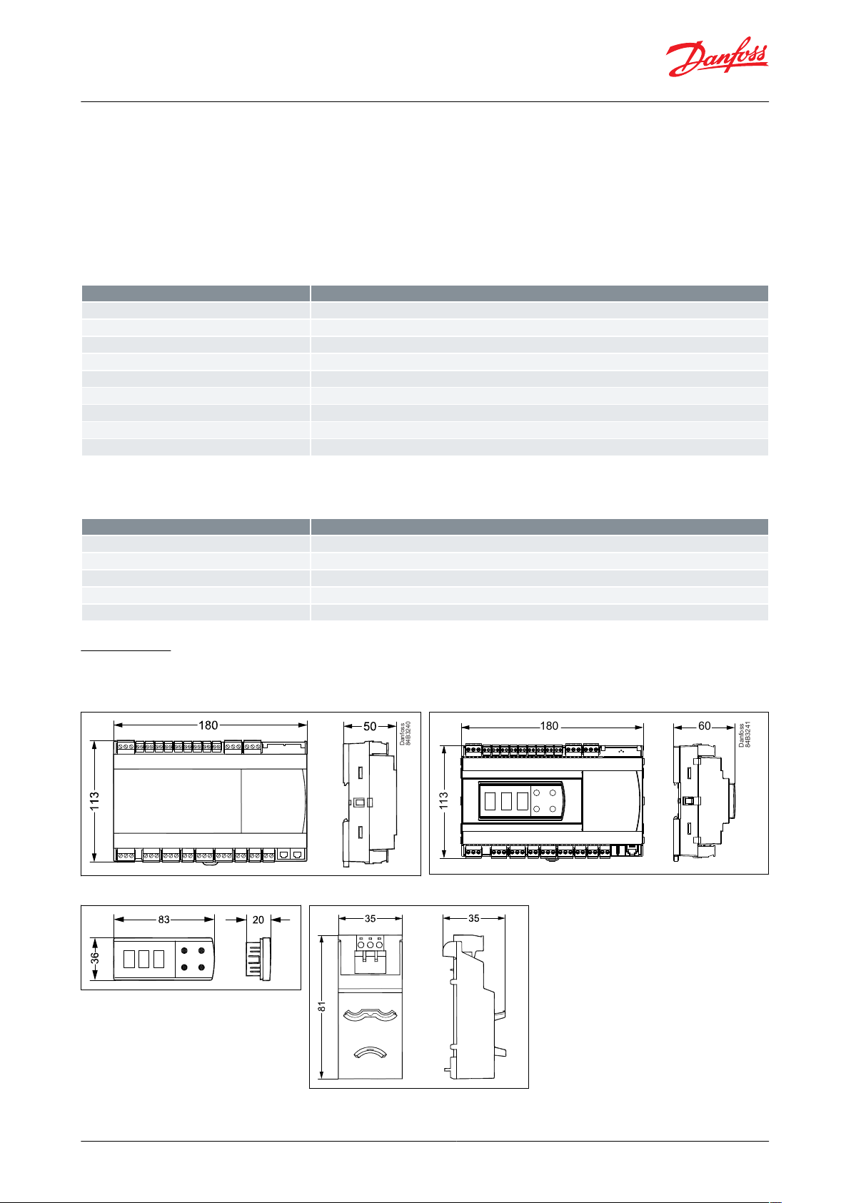
Danfoss
84B3240
113
180 60
Danfoss
84B3241
Danfoss
84B3242
Danfoss
84B3245
Function data
Value
Display
LED 3 digit
External display, AK-CC55 Single Coil UI
1 external display
External display, AK-CC55 Single Coil
2 external displays
External display connection
RJ12
Max. display cable length [m]
100 m
Data communication built-in
MODBUS
Data communication option
AK-OB55 Lon RS485 module (Not AK-CC55 Compact)
Clock battery backup power reserve
4 days
Mounting
DIN rail
Environmental conditions
Value
Ambient temperature range, transport [°C]
0 – 55 °C
Ambient temperature range, storage [°C]
-40 – 70 °C
Enclosure rating IP
IP20
Relative humidity range [%]
20 – 80%, non-condensing
Shocks/Vibrations
No shocks and vibrations allowed
AK-CC55 Single Coil and AK-CC55 Single Coil UI
NOTE:
• DO2 to DO6 are 16 A relays.
• Max. load must be observed.
• DO5 / DO6 is recommended for load with high inrush current e.g. EC Fan and LED light.
• All relays are sealed for use with ammable refrigerant like Propane R290.
• Compliance with EN 60 335-2-89: 2010 Annex BB.
Function data
Table 53: Function data
Environmental conditions
Table 54: Environmental conditions
Dimensions
Measurements are in mm.
Figure 59: AK-CC55 Single Coil
Figure 61: AK-UI55 Set
Figure 60: AK-CC55 Single Coil UI
Figure 62: AK-OB55
© Danfoss | Climate Solutions | 2022.03 BC364229688105en-000201 | 73
Page 74

Type
Symbol
Function
Code no.
AK-CC55 Single Coil
Case controller for one AKV valve
084B4082
AK-CC55 Single Coil UI
Case controller for one AKV valve
Integrated display with control buttons
084B4083
AK-UI55 Info
External display
084B4077
AK-UI55 Bluetooth
External display with Bluetooth operation
084B4075
AK-UI55 Set
External display with control buttons
084B4076
AK-UI55 Mounting Base
Danfoss
80G8236
Mounting kit for display types: AK-UI55 Set, AK-UI55 Bluetooth, AK-UI55 Info
084B4099
AK-UI cable
External display cable with RJ12 connector. 3 m
084B4078
AK-UI cable
External display cable with RJ12 connector. 6 m
084B4079
AK-OB55 Lon
Data communication module Lon
Can be mounted in Single Coil and Multi Coil versions
084B4070
MMIMYK
Danfoss
80G8284
Gateway between AK-CC55 and PC installed with KoolProg software
080G0073
AK-CC55 Single Coil and AK-CC55 Single Coil UI
Ordering
The list contains the components that make up an AK-CC55 Single Coil setup. For other Danfoss products
mentioned in the document, such as sensors and valves, refer to relevant product documentation.
Table 55: Ordering
© Danfoss | Climate Solutions | 2022.03 BC364229688105en-000201 | 74
Page 75

Control
Certication
Mark
Country
Single Coil / Single Coil UI
EMC/LVD/RoHS
CEEUSingle Coil/Single Coil UI
UL recognized
cURus
NAM (US and Canada)
Single Coil / Single Coil UI
ACMA (EMC)
RCM
Australia/New Zealand
Single Coil / Single Coil UI
LVE/EMC/RoHS
EAC
Russia, Kazakhstan, belarus
Single Coil / Single Coil UI
LVD/EMC/RoHS
UA
Ukraine
Display module
Certication
Mark
Country
AK-UI55 Bluetooth
REDCEEU
AK-UI55 Bluetooth
FCC
FCC ID
USA
AK-UI55 Bluetooth
IC (ISED)
IC ID
Canada
AK-UI55 Bluetooth
CMIIT
CMITT ID
China
AK-UI55 Bluetooth
ACMA (EMC/Wireless)
RCM
Australia
AK-UI55 Bluetooth
RSM (EMC/Wireless)
RCM
New Zealand
AK-UI55 Bluetooth
EMC/LVD/Wireless
UA
Ukraine
AK-UI55 Bluetooth
ANATEL
ANATEL ID
Brazil
AK-UI55 Bluetooth
SUBTEL
N/A
Chile
AK-UI55 Bluetooth
RoHS
EAC
Russia, Kazakhstan, Belarus
AK-UI55 Info
EMC/LVD
UA
Ukraine
AK-UI55 Info
ACMA (EMC)
RCM
Australia
AK-UI55 Info
RSM (EMC)
RCM
New Zealand
AK-UI55 Info
RoHS
EAC
Russia, Kazakhstan, belarus
AK-UI55 Set
EMC/LVD
UA
Ukraine
AK-UI55 Set
ACMA (EMC)
RCM
Australia
AK-UI55 Set
RSM (EMC)
RCM
New Zealand
AK-UI55 Set
RoHS
EAC
Russia, Kazakhstan, belarus
Option module
Certication
Mark
Country
AK-OB55 LoN
EMC/LVD
UA
Ukraine
AK-CC55 Single Coil and AK-CC55 Single Coil UI
Certicates, declar
ations, and approvals
The list contains all certicates, declarations, and approvals for this product type. Individual code number may have
some or all of these approvals, and certain local approvals may not appear on the list.
Some approvals may change over time. You can check the most current status at danfoss.com or contact your local
Danfoss representative if you have any questions.
Table 56: Controller
Table 57: Display module
Table 58: Option module
Controllers/displays/option module:
CB certificate including all deviation according to IEC 60730-1 and 2-9
Relays:
T
ested according to IEC 60079-15
© Danfoss | Climate Solutions | 2022.03 BC364229688105en-000201 | 75
Page 76

AK-CC55 Single Coil and AK-CC55 Single Coil UI
Statements for the AK-UI55 Bluetooth display
FCC COMPLIANCE STATEMENT
CAUTION:
Changes or
complies with Part 15 of the FCC Rules. Operation to the following two conditions: (1) This device may not cause
harmful interference, and (2) this device must accept any interference received, including interference that may
cause undesired operation.
INDUSTRY CANADA STATEMENT
This device complies with Industry Canada license-exempt RSS standard(s). Operation is subject to the following
two conditions: (1) this device may not cause interference, and (2) this device must accept any interference,
including interference that may cause undesired operation of the device.
Le présent appareil est conforme aux CNR d'Industrie Canada applicables aux appareils radio exempts de licence.
L'exploitation est autorisée aux deux conditions suivantes : (1) l'appareil ne doit pas produire de brouillage, et (2)
l'utilisateur de l'appareil doit accepter tout brouillage radioélectrique subi, même si le brouillage est susceptible
d'en compromettre le fonctionnement.
modications not expressly approved could void your authority to use this equipment This device
© Danfoss | Climate Solutions | 2022.03 BC364229688105en-000201 | 76
Page 77

Online support
Play Store
App Store
oss oers a wide range of support along with our products, including digital product information, software,
Danf
mobile apps, and expert guidance. See the possibilities below.
The Danfoss Product Store
The Danfoss Product Store is your one-stop shop for everything product related—no matter where
you are in the world or what area of the cooling industry you work in. Get quick access to essential
information like product specs, code numbers, technical documentation, certications, accessories,
and more.
Start browsing at store.danfoss.com.
Find technical documentation
Find the technical documentation you need to get your project up and running. Get direct access to
our ocial collection of data sheets, certicates and declarations, manuals and guides, 3D models
and drawings, case stories, brochures, and much more.
Start searching now at www.danfoss.com/en/service-and-support/documentation.
Get local information and support
Local Danfoss websites are the main sources for help and information about our company and
products. Find product availability, get the latest regional news, or connect with a nearby expert—all
in your own language.
Find your local Danfoss website here: www.danfoss.com/en/choose-region.
AK-CC55 Connect
Make service easy with the free AK-CC55 Connect app. Via a Danfoss Bluetooth display you can
connect to an AK-CC55 case controller and get a visual overview of the display functions. The app
ensures smooth interaction with a Danfoss AK-CC55 case controller in a user-friendly design.
Download the app here:
Any information, including, but not limited to information on selection of product, its application or use, product design, weight, dimensions, capacity or any other
technical data in product manuals, catalogues descriptions, advertisements, etc. and whether made available in writing, orally, electronically, online or via download,
shall be considered informative, and is only binding if and to the extent, explicit reference is made in a quotation or order conrmation. Danfoss cannot accept any
responsibility for possible errors in catalogues, brochures, videos and other material. Danfoss reserves the right to alter its products without notice. This also applies to
products ordered but not delivered provided that such alterations can be made without changes to form, t or function of the product. All trademarks in this material
are property of Danfoss A/S or Danfoss group companies. Danfoss and the Danfoss logo are trademarks of Danfoss A/S. All rights reserved.
© Danfoss | Climate Solutions | 2022.03 BC364229688105en-000201 | 77
 Loading...