

Page 1
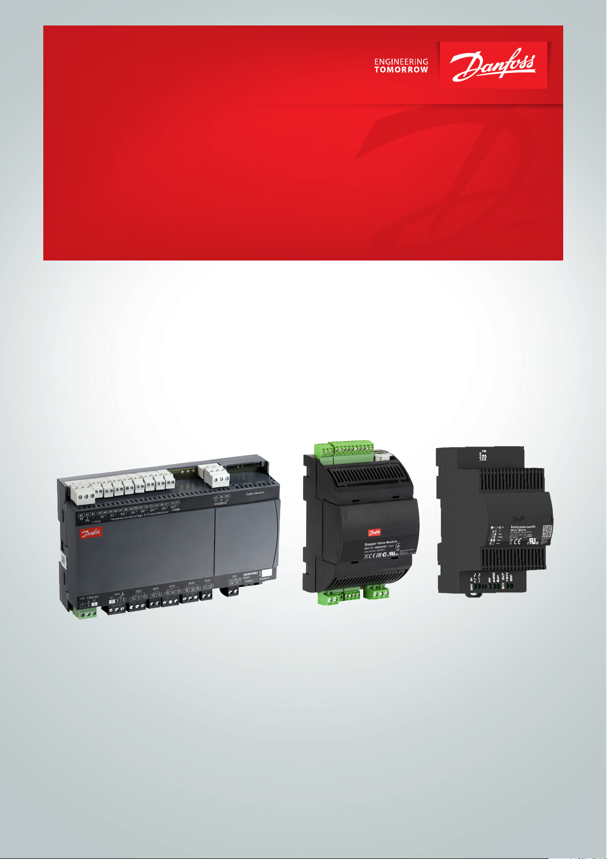
Operating Guide
Control of stepper motor valves
with AK-CC55 Single Coil, EKE 1P and EKE 2U
Wiring and controller set-up
Page 2
84B8326
Operating Guide | Control of stepper motor valves with AK-CC55 Single Coil, EKE 1P, EKE 2U
Introduction
Wiring example
AK-CC55 Single Coil can be set up to control stepper motor valves.
This document will describe how the wiring is done and how the controller can be set up.
The stepper motor valve is controlling the injection of refrigerant into the evaporator, hence replacing
the AKV valve. The AKV valve output can then be used to control a solenoid valve in the liquid line. The
solenoid valve will close in case of power failure.
A stepper motor driver is needed to convert the analogue output that the AK-CC55 controller can
deliver to a stepper motor output. The stepper motor driver used here is the EKE 1P.
There is no bus communication between the AK-CC55 controller and the EKE 1P, but the controller can
receive a “--- Driver alarm” in case of an alarm on the EKE 1P.
A back-up power module can be installed to secure closure of the stepper motor valve in case of
power failure. The power module used here is the EKE 2U.
This stepper driver feature is implemented in software version 1.53 of the AK-CC55 Single Coil
controller.
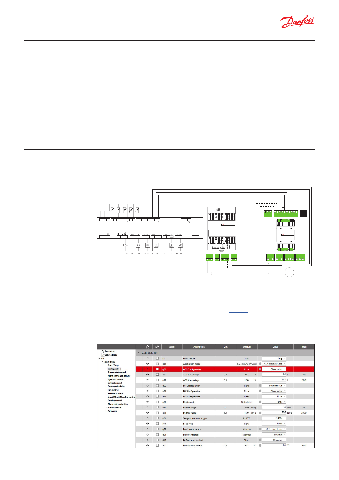
The sketch below is showing how the analogue output on the AK-CC55 controller is connected to the
EKE 1P stepper motor driver where the stepper motor valve is connected.
The sketch also shows how the back-up power module is integrated.
When the wiring is done, the controller and the two modules can be powered up.
P
132
40
41 42 43 44 45 46 47 48 49 50 51 52 53 54 60 61 70 71 83 84
s
5V
S2 S3 S4 S5 S6 DI2AO1
Pe
115 – 230 V AC
LN
1
AKVAlarm RailheatDefrost LightFan
2 3 7 8 9 10 11 12 13 14 21 22 30 3115 16 17 18 19 20
DI1/
AI7
0 – 10 V
Application 4
+
B-A
MODBUS
85
115 – 230 V AC
LOAD SWITCH
Backup power module
DI3
EKE 2U - 080G5555
SoH communication (optional)
COM
D-D+RGND
RS-485
5V+
DI2
COM
RGND
D-
D+
Superheat controller
EKE xx - 080G5xxx
Main switch
DI1/Com.
DI1
5V+
DI2
CAN RJ
COM
AI4
AI3
AI2
AI1
COM
CAN RJ
DI1
COM
AI4
AI3
AI2
AI1
COM
Danfoss
Setting up AK-CC55 Single
Coil using KoolProg
–/~
+/~
GND
Bat+
A1A2B1B2NO1C1NC1
+/~
GND
Bat+
Stepper valve digital output
A1A2B1B2NO1C1NC1
M
Power
24 V
PWR 24 VWbat
PF
SoH
SGND
GND
–/~
+/~
+/~
-/~
+24 V
RED
GREEN
–/~
Products used in this example:
AK-CC55 Single Coil, 084B4082, SW version 1.53
EKE 1P, 080G0325, SW version 2.10
EKE 2U, 080G5555, PV00
KoolProg is a PC software which can be downloaded from the KoolProg download site where the
User Guide can also be found. Please notice that the User Guide describes the need for an MMIMYK
interface (Code No. 080G0073), a Mini USB cable and an RJ11 cable (Code No. 080G0075) for
connection with AK-CC55 controller. The controller can also be set up using the AK-CC55 Connect App
(a mobile phone application) via the AK-UI55 Bluetooth display and it can be set up via the AK-SM
800A type System Manager.
2 | AQ391029518843en-000101 © Danfoss | Climate Solutions | 2021.11
Page 3

Operating Guide | Control of stepper motor valves with AK-CC55 Single Coil, EKE 1P, EKE 2U
The picture on the previous page shows an example of how the AK-CC55 Single Coil controller can be
set up.
• Application mode (q61) is set to “4” (as an example)
• AO1 Configuration (q09) on the analogue output is set to “Valve driver”
• AO1 Minimum voltage (o27) on the analogue output is set to “0” V
• AO1 Maximum voltage (o28) on the analogue output is set to “10” V
• DI2 Configuration (o37) on the digital input 2 is set to “Valve driver”
With this setting the analogue output will send a signal in the range of 0 to 10 V to the stepper driver
module and should an alarm situation be raised on the stepper driver, the AK-CC55 controller will
receive the alarm message “Valve driver”, which can be seen in the alarm list on the controller and
hence on the system manager.
Setting up EKE 1P using the
MMIGRS2 display
The set-up requires the use of the MMIGRS2 display (Code No. 080G0294) and the RJ11 cable (Code
No. 080G0075). But, this EKE module cannot be set up via KoolProg PC software.
The MMIGRS2 display has to be connected to the EKE 1P stepper motor driver via the RJ11 cable
before the set-up can start.
The settings shown here sets up the driver:
• Press “Enter” to activate display.
• Press “Enter” and hold “Enter” a couple of seconds to activate “Setup & service” (an access code might
have to be set)
• START/STOP
– Main switch is already ON (by default with Application 1) so it has to be switched OFF to allow
changes to Application Mode.
– Main switch: OFF
– Application Mode: 2
• Device config.
– Mode settings: AI HP/Rec., HP exp, Rec. exp., AI valve
– Mode set to: AI valve
• AI valve in…
– AI valve input scale: 0 – 10 V
• I/O
– Output Relay control: Auto
– Configure:
– DI1 Active: ON
– DI2 Active: ON
• Alarm config.
– Battery Alarm options: NO, EKE 2U, Bat.
– Battery alarm: EKE2U
• Valve config.
– Valve configuration: e.g. CCMT-3L
© Danfoss | Climate Solutions | 2021.11 AQ391029518843en-000101 | 3
Page 4

EKE 2U alarm and status on
EKE 1P
The following screenshots are captured from an MMIGRS2 display.
Alarm signalling from EKE 2U (SoH) can trigger a “Driver alarm” on AK-CC55 via EKE 1P / DO
EKE 2U alarm and status on
EKE 1P (KoolProg & Service
Tool)
EKE 1P: No alarm on EKE 2U (DO
= OFF)
EKE 1P: Alarm for Battery Critical
Low voltage
EKE 1P: Battery charging on EKE
2U
DO = ON (DI2 alarm on AK-CC55
Single Coil)
EKE 1P: Battery Fault on EKE
2U because the Power supply is
interrupted (low battery voltage)
Note: The alarm is ON because of
"Battery critical low voltage".
The following screenshots are captured from KoolProg and AK-ST 500 Service Tool.
• “--- Driver alarm” on AK-CC55 Single Coil, so, the alarm chain
works!
• However, NO bus communication between EKE 1P and AK-CC55
Code numbers
AK-CC55 Single Coil 084B4082
AK-CC55 Single Coil UI 084B4083
EKE 1P 080G0325
EKE 2U 080G5555
MMIGRS2 080G0294
Wire for display 1.5 m 080G0075
Wire for display 3 m 080G0076
© Danfoss | Climate Solutions | 2021.11 AQ391029518843en-000101 | 4
ADAP-KOOL®
 Loading...