

User Guide
Controller for appliance control
AK-CC 525A
ADAP-KOOL® Refrigeration control systems
Introduction
Application
Complete refrigeration appliance control.
Advantages
• Energy optimisation of the whole refrigeration appliance
• Quick set-up with predefined settings
• Built-in data communication
• Built-in clock function with power reserve
Principle
The temperature in the appliance is registered by one or two
temperature sensors which are located in the air flow before the
evaporator (S3) or after the evaporator (S4) respectively. A setting
for thermostat, alarm thermostat and display reading determines
the influence the two sensor values should have for each individual function.
The temperature of the evaporator is registered with the S5 sensor
which can be used as a defrosting sensor.
In addition to the outlet to the electronic injection valve of the
type AKV, the controller has 5 relay outputs.
Functions
• Day/night thermostat with ON/OFF or modulating principle
• Switch between thermostat settings via digital input
• Adaptive control of superheat
• Start of defrost via schedule, digital input or network
• Natural or electric defrost
• Stop of defrost on time and/or temperature
• Coordination of defrosting among several controls
• Pulsing of fans when thermostat is satisfied
• Door function
• Light control
• Factory calibration that will guarantee a better measuring accuracy than stated in the standard EN 13485 without subsequent
calibration (Pt 1000 ohm sensor)
• Integrated MODBUS communication with the option of mounting a LonWorks communication card.
Appliance examples
Application
The controller can be set so that relay DO3 is used for one of the
following functions:
• Cooling
Here the relay is active when cooling is necessary.
• Rail heat
Here the relay controls the effect to the rail heat.
DO3
Contents
Introduction ....................................................................................................... 2
Regulating functions ....................................................................................... 3
Survey of functions .......................................................................................... 9
Operation .......................................................................................................... 19
2 Manual RS8HB302 © Danfoss 2016-07 AK-CC 525A
Menu survey .....................................................................................................20
Connections ..................................................................................................... 24
Data ..................................................................................................................... 26
Ordering ............................................................................................................27
Regulating functions
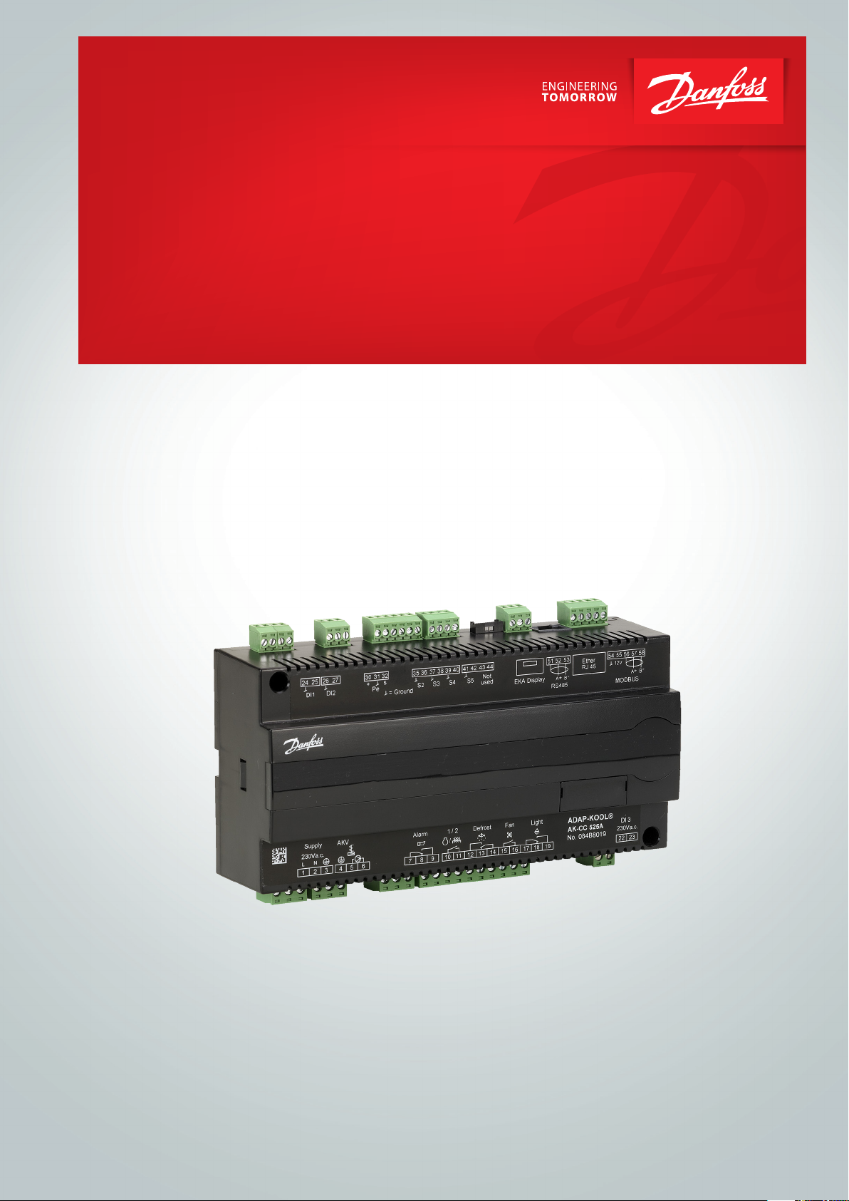
Liquid injection
Liquid injection in the evaporator is controlled by an electronic
injection valve of the type AKV. The valve functions as both expansion valve and solenoid valve. The valve opens and closes using
signals from the controller.
The function contains an adaptive algorithm which independently
adjusts the valve’s opening so that the evaporator constantly supplies optimum refrigeration.
Superheat can be measured via:
• Pressure sensor Po and temperature sensor S2
For this use a correct measurement of superheat is achieved
under all conditions which ensures a very robust and precise
control.
The signal from one pressure transmitter can be used by several
controllers, but only if there is no significant pressure difference
between the evaporators in question.
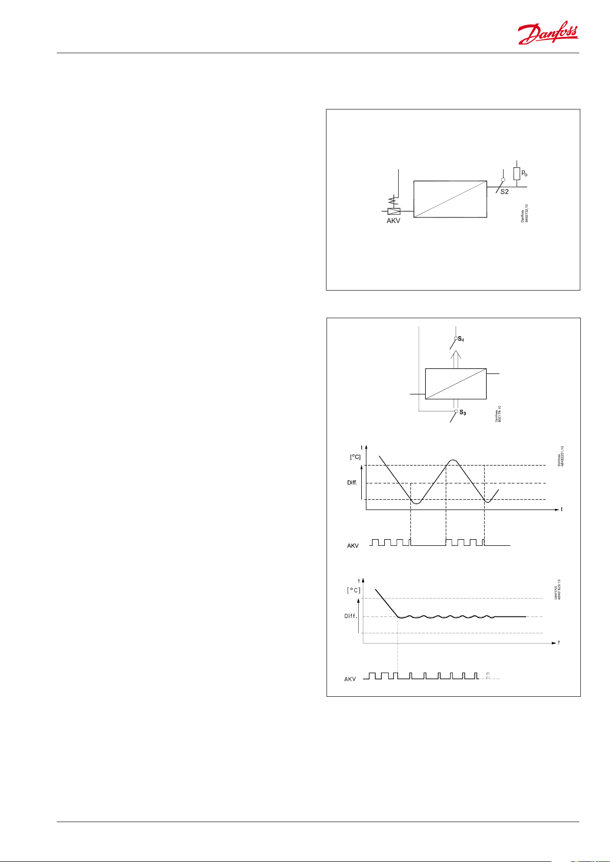
Temperature control
The temperature in the appliance is registered by one or two
temperature sensors which are located in the air flow before the
evaporator (S3) or after the evaporator (S4) respectively. A setting
for the thermostat, alarm thermostat and display reading determines how much the two sensor values should influence each
individual function, e.g. 50% will produce an equal value from
both sensors.
The actual temperature control can take place in two ways: as an
ordinary ON/OFF regulation with a differential, or as a modulating control there the temperature variation will not be nearly as
great as in ON/OFF control. There is however a limit to the use of
a modulating control as it can only be used in central plant. In a
decentralised plant the thermostat function with ON/OFF control
should be selected.
In a central plant the thermostat function may either be selected
for ON/OFF control or modulating control.
Temperature monitoring
Just as is possible for the thermostat, the alarm monitoring can be
set with a weighting between S3 and S4 so that you can decide
how much the two sensor values should influence the alarm
monitoring. Minimum and maximum limits can be set for alarm
temperature and time delays. A longer time delay can be set for
high temperature alarm. This time delay is active after defrosting
and start-up.
AK-CC 525A Manual RS8HB302 © Danfoss 2016-07 3
Thermostat displacement
Thermostat displacement can be used beneficially for appliances
where different product types are stored which require different
temperature conditions. It is possible to change between two different thermostat settings via a contact signal on a digital input.
During a thermostat displacement, the alarm limits will be displaced accordingly.
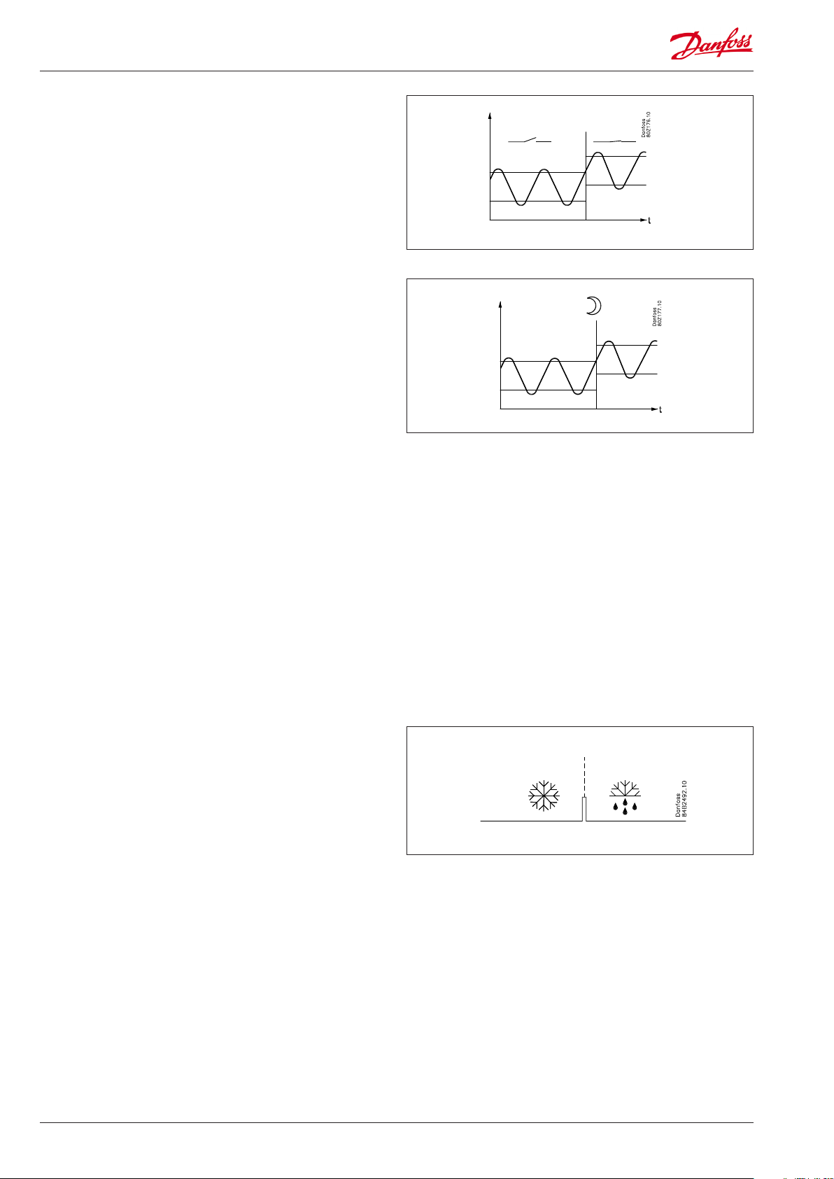
Night setback of thermostat value
In refrigeration appliances there may be big load differences
between the shop’s opening and closing hours, especially if night
lids/blinds are used. The thermostat reference may be raised here
without it having any effect on the product temperature.
Change-over between day and night operation can take place, as
follows:
• via an external switch signal.
• via a signal from the data communication system.
• Alarm limits are not displaced during night operation.
Appliance shut-down
The function closes the AKV valve and all outputs are switched off.
The cooling appliance is stopped like the “Main switch”, but this
happens without an “A45 standby alarm”.
The function can be enabled by a switch on the DI input or via a
setting through data communication.
Defrost
Depending on the application you may choose between the following defrost methods:
Natural: Here the fans are kept operating during the defrost
Electric: The heating element is activated
Gas: Simple hotgas defrost where compressor is running
during defrost.
Defrost sequence
1) Pump down
2) Defrost
3) Waiting position after defrost (coordinated defrost only)
4) Drip off
5) Delay of fan
Start of defrost
A defrost can be started in different ways
Interval: Defrost is started at fixed time intervals, say, every
eighth hour. An interval must ALWAYS be set to
a "higher" value than the period set between two
defrostings when a schedule or network signal is used.
Refrigeration time: Defrost is started at fixed refrigeration time
intervals, in other words, a low need for refrigeration will
”postpone” the defrost
Schedule: Here defrost can be started at fixed times of the
day and night. However, max. 6 times
Contact: Defrost is started with a contact signal on a digital input
Network: The signal for defrost is received from a system unit
via the data communication
Manual: An extra defrost can be activated from the display lower-
most button or via parameter setting
All the mentioned methods can be used at random – if just of
them is activated a defrost will be started.
Stop of defrost
Defrosting can be stopped by either:
• Time
• Temperature (with time as safety).
4 Manual RS8HB302 © Danfoss 2016-07 AK-CC 525A
Coordinated defrost
There are two ways in which coordinated defrost can be arranged.
Either with wire connections between the controllers or via data
communication
Wire connections
The digital input DI2 is connected between the current controllers.
When one controller starts a defrost all the other controllers will
follow suit and likewise start a defrost. After the defrost the individual controllers will move into waiting position. When all are in
waiting position there will be a change-over to refrigeration.
Coordination via data communication
Here the system unit handles the coordination.
The controllers are gathered in defrosting groups and the system
unit ensures that defrosting is started in the group according to a
weekly schedule.
When a controller has completed defrosting, it sends a message
to the system unit and then goes into a waiting position. When
every controller in the group is in a waiting position, refrigeration
is again permitted in all the individual controllers.
Defrost on demand
1 Based on refrigeration time
When the aggregate refrigeration time has passed a fixed time,
a defrost will be started.
Max. 10
System manager
Melting function
This function will stop the air flow in the evaporator from being reduced by frost created by uninterrupted operation for a long time.
The function is activated if the thermostat temperature has
remained in the range between -5°C and +10°C for a longer
period than the set melting interval. The refrigeration will then be
stopped during the set melting period. The frost will be melted
so that the air flow and hence the evaporator’s capacity will be
greatly improved.
Real-time clock
The controller has a built-in real-time clock which can be used to
start defrosts. This clock has a power reserve of four hours.
If the controller is equipped with data communication, the clock
will automatically be updated from the system unit.
AK-CC 525A Manual RS8HB302 © Danfoss 2016-07 5
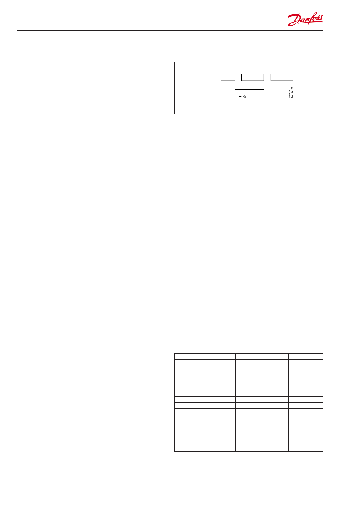
Fan
Pulse control
To obtain energy savings it is possible to pulse control the power
supply to the fans at the evaporators.
Pulse control can be accomplished in one of the following ways:
- during the thermostat’s cutout period (cold room)
- during night operation and during the thermostat’s cutout period (appliance with night lid)
(The function is not actual when r14=2, i.e. modulating
regulation).
A period of time is set as well as the percentage of this period of
time where the fans have to be operating.
Cutout of fans during plant breakdowns
If the refrigeration in a breakdown situation stops, the
temperature in the cold room may rise quickly as a result of the
power supply from large fans. In order to prevent this situation the
controller can stop the fans if the temperature at S5 exceeds a set
limit value.
Light function
The function can be used for controlling the light in a refrigeration
appliance or in a cold room. It can also be used for controlling a
motorised night blind.
Period time
The light function can be defined in three ways:
- the light is controlled via a signal from a door contact. Together
with this function a time delay can be set so that the light is kept
on for a period of time after the door has been closed.
- the light is controlled via the day/night function
- the light is controlled via the data communication from a system
unit.
Here there are two operational options if data communication
should fail:
- The light can go ON
- The light can stay in its current mode.
The light load must be connected to the NC switch on the relay.
This ensures that the light remains on in the appliance if power to
the controller should fail.
The light is switched off when "r12" (Main switch) is set to off (see
o98).
Digital inputs
There are two digital inputs DI1 and DI2 with contact function and
one digital input DI3 with high voltage signal.
They can be used for the following functions:
- Retransmission of contacts position via data communication
- Door contact function with alarm
- Starting a defrost
- Main switch - start/stop of cooling
- Night setback
- Thermostat displacement
- General alarm monitoring
- Case shut down
- Coordinated defrost (DI2 only)
- Forced closing of valve (DI 3 only)
Function Input/Settings menu Setting
DI1 DI2 DI3
o02 o37 o84
Not used + + + 0
Follows DI’s status + + + 1
Door contact function + + + 2
Door alarm + + + 3
Start defrost + + + 4
Main switch + + + 5
Nighttime operation + + + 6
Thermostat displacement + + + 7
DI alarm when closed + + 8
DI alarm when open + + 9
Coordinated defrost + 13
Forced close + 14
Case shutdown + + + 15
Example
If DI1 is used to start a defrost cycle, o02 must be set to 4.
6 Manual RS8HB302 © Danfoss 2016-07 AK-CC 525A
Forced closing
The AKV valves can be closed with an external signal ( "Forced
closing").
The function must be used in connection with the compressor’s
safety circuit, so that there will be no injection of liquid into the
evaporator when the compressor is stopped by the safety controls. (However not at low pressure – LP).
If a defrost cycle is in progress, the forced closing status will not
be re-established until the defrost is completed. Otherwise, the
defrost cycle is stopped immediately once the signal is received.
The function is defined in o90. The signal can be received from the
DI3-input or via the data communication.
During a forced closing the fans can be defined to be stopped or
in operation.
Door contact
The door contact function can via the digital inputs be defined for
two different applications:
Alarm monitoring
The controller monitors the door contact and delivers an alarm
message if the door has been opened for a longer period than
the set alarm delay.
Alarm monitoring and stop of refrigeration
When the door is opened the refrigeration is stopped, i.e. the
injection, the compressor and the fan are stopped and light
switch on.
If the door remains open for a longer time than the set restart
time, refrigeration will be resumed. This will ensure that
refrigeration is maintained even if the door is left open or if the
door contact should be defective. If the door remains open for
a longer period than the set alarm delay an alarm will also be
triggered.
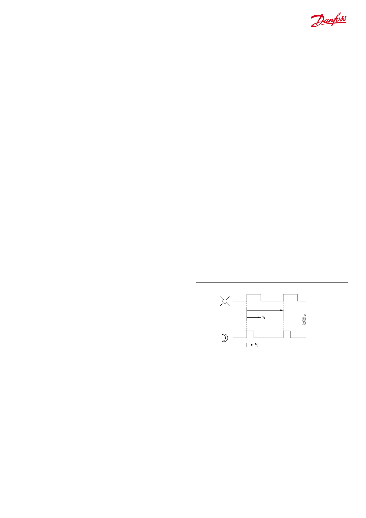
Railheat (o61=2)
It is possible to pulse-control the power to the rail heat in order
to save energy. Pulse control can be controlled according to day/
night load.
Pulse control according to day and night
Various ON periods can be set for day and night operation.
A period time is set as well as the percentage part of the period in
which the rail heat is ON.
During defrosting
During defrosting rail heat will be active, as selected in setting
d27.
AK-CC 525A Manual RS8HB302 © Danfoss 2016-07 7
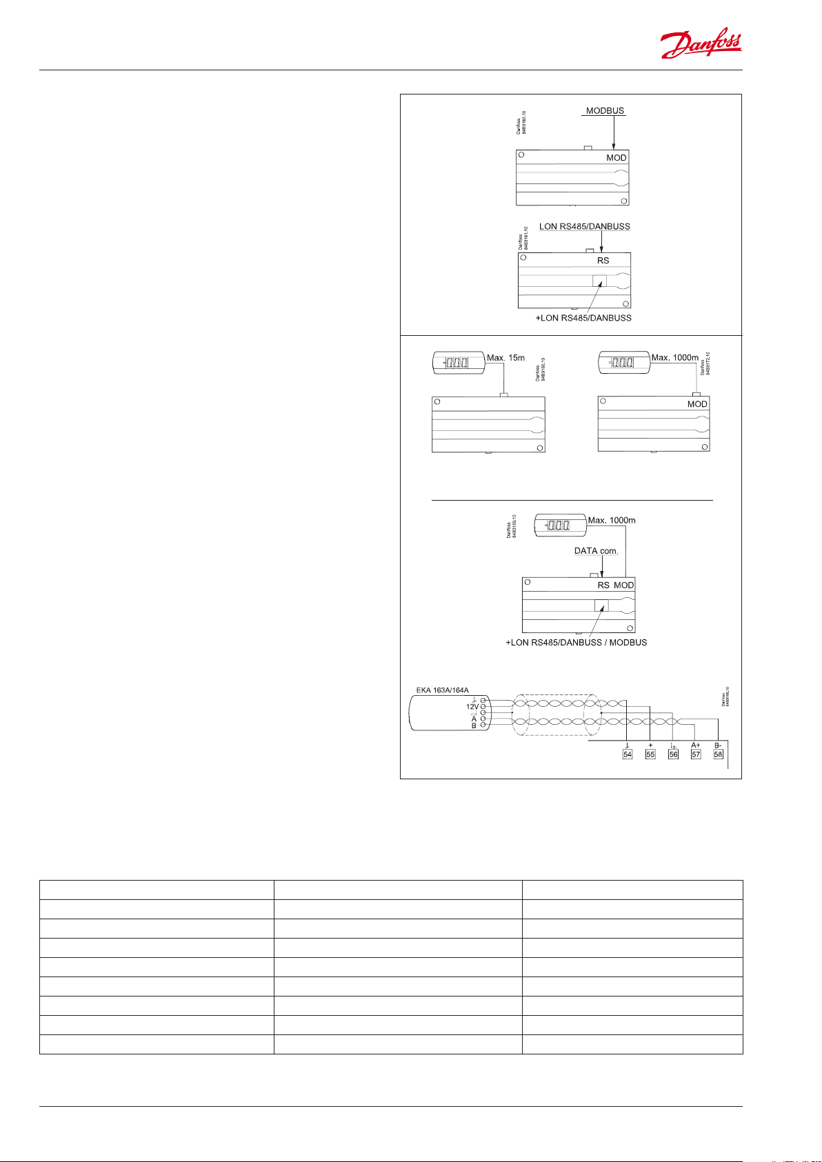
Data communication
The controller has fixed built-in MODBUS data communication.
If there is a requirement for a different form of data
communication, a Lon RS 485 or DANBUSS module can be
inserted in the controller.
The connection must then be to terminal RS 485.
(To use a Lon RS 485 module and gateway type AKA 245 the AKA
245 must be Version 6.20 or higher.)
Display
The controller has one plug for a display. Here display type EKA
163B or EKA 164B (max. length 15m) can be connected.
EKA 163B is a display for readings.
EKA 164B is both for readings and operation.
The connection between display and controller may be with a
cable which has a plug at both ends.
If the distance between display and controller is greater than 15
m, the connection must take another form.
An extra module must also be mounted in the controller if data
! Address
o03 > 0
communication is used.
The built-in MODBUS data communication is used so that the
display connection and the data communication to the other
controllers must take place via a module. The module can be:
Lon RS 485, DANBUSS or MODBUS.
When a display is to be connected to the built-in MODBUS, the
display can advantageously be changed to one of the same type,
but with Index A (version with screw terminals).
The controllers address must be set higher than 0 in order for the
display to be able to communicate with the controller.
If connection of two displays is required, one must be connected
to the plug (max. 15 m) and the other must then be connected to
the fixed data communication.
Important
All connections to the data communication MODBUS, DANBUSS
and RS 485 must comply with the requirements for data
communication cables. See literature: RC8AC.
Override
The controller contains a number of functions which can be used together with the override function in the master gateway/system
manager.
Function via data communication Function in gateway/system manager Used parameters in AK-CC 525A
Start of defrosting Defrost control / Time schedule / Defrost group --- Def start
Coordinated defrost Defrost control / Defrost group --- HoldAfterDef / - - - DefrostState
Prevent defrost start --- Disable Def
Day/Night schedule Day/Night control / Time schedule / Light zone --- Night setback
Light control Day/Night control / Time schedule O39 light Remote
Forced closing Forced Close / Injection ON / AKC ON --- Forced cl.
P0 optimization P0 Optimization The controller supports P0 optimization
Case shutdown Day/night control / Time schedule --- Case shutdown
8 Manual RS8HB302 © Danfoss 2016-07 AK-CC 525A
Survey of functions
Function Para-
meter
Normal display
Normally the temperature value from one of the two thermostat sensors S3 or S4 or a
mixture of the two measurements is displayed.
In o17 the ratio is determined.
Thermostat r- - Thermostat control
Set point
Regulation is based on the set value plus a displacement, if applicable. The value is set
via a push on the centre button.
The set value can be locked or limited to a range with the settings in r02 and r 03.
The reference at any time can be seen in "u91 Cutout temp".
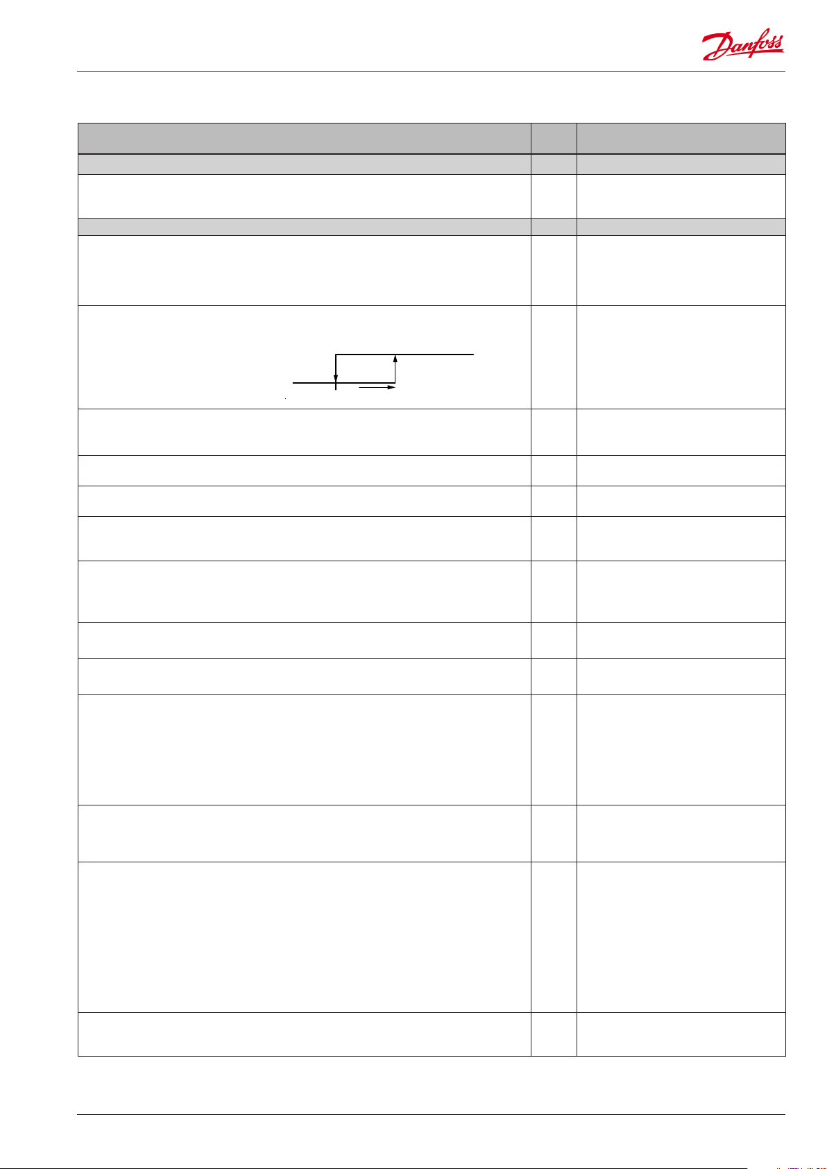
Differential
When the temperature is higher than the reference + the set differential, the compressor relay will be cut in. It will cut out again when the temperature comes down to
the set reference.
Ref. Dif.
Setpoint limitation
The controller’s setting range for the setpoint may be narrowed down, so that much
too high or much too low values are not set accidentally - with resulting damages.
To avoid a too high setting of the setpoint, the max. allowable reference value may be
lowered.
To avoid a too low setting of the setpoint, the min. allowable reference value may be
increased.
Correction of the display’s temperature
If the temperature at the products and the temperature received by the controller are
not identical, an offset adjustment of the display temperature can be carried out.
Temperature unit
Set here if the controller is to show temperature values in °C or in °F.
Correction of signal from S4
Compensation possibility due to long sensor cable
Correction of signal from S3
Compensation possibility due to long sensor cable
Start / stop of refrigeration
With this setting refrigeration can be started, stopped or a manual override of the
outputs can be allowed. (For manual control the value is set at -1. Then the AKV outlet
and the relay outlets can be force-controlled by the respective reading parameters
(u23, u58, etc.). Here the read value can be overwritten.)
Start / stop of refrigeration can also be accomplished with the external switch function connected to a DI input.
Stopped refrigeration will give a ”Standby alarm”.
Night setback value
The thermostat’s reference will be the setpoint plus this value when the controller
changes over to night operation. (Select a negative value if there is to be cold accumulation.)
Thermostat function
Here it is defined how the thermostat is to operate. Either as an ordinary ON/OFF thermostat or as a modulating thermostat.
1: ON/OFF thermostat
2: Modulating
Parameter by operation via data
communication
Display air (u56)
r00 Cutout °C
r01 Differential
r02 Max cutout °C
r03 Min cutout °C
r04 Disp. Adj. K
r05 Temp. unit
°C=0. / °F=1
(Only °C on AKM, whatever the setting)
r09 Adjust S4
r10 Adjust S3
r12 Main Switch
1: Start
0: Stop
-1: Manual control of outputs allowed
r13 Night offset
r14 Therm. mode
When operation is ”modulating” the AKV valve will limit the flow of refrigerant so that
the temperature variation will be less than for the ON/OFF thermostat.
The differential (r01) must not be set lower than 2K for "modulating".
In a decentralised plant you must select the ON/OFF thermostat setting.
Selection of thermostat sensor
Here you define the sensor the thermostat is to use for its control function. S3, S4, or a
combination of them. With the setting 0%, only S3 is used (Sin). With 100%, only S4.
AK-CC 525A Manual RS8HB302 © Danfoss 2016-07 9
r15 Ther. S4 %

Melt function
Only for control of refrigeration (-5 to +10°C). The function ensures that the evaporator will not be blocked by frost. Here you set how often the function is to stop the
refrigeration and hence transform the frost to water (or ice if there is too much frost).
r16 MeltInterval
Melt period
Here you set how long an on-going melt function is to last.
Thermostat displacement
The thermostat reference can be displaced in a positive or negative direction when a
signal is received on a DI input. The value is set in Kelvin.
When the reference displacement is active, the two alarm limits, A13 and A14, will be
displaced accordingly.
Alarm A- - Alarm settings
The controller can give alarm in different situations. When there is an alarm all the
light-emitting diodes (LED) will flash on the external display, and the alarm relay will
cut in.
Alarm delay (short alarm delay on air temperature)
If the upper or the lower alarm limit values are exceeded, a timer function will commence. The alarm will not become active until the set time delay has been passed.
The time delay is set in minutes.
Time delay for door alarm
The time delay is set in minutes.
The function is defined in o02 , o37 or in o84.
Time delay for cooling (long alarm delay)
This time delay is used during start-up and during defrost.
There will be change-over to the normal time delay (A03) when the temperature has
dropped below the set upper alarm limit.
The time delay is set in minutes.
Upper alarm limit
Here you set when the alarm for high temperature is to start. The limit value is set in
°C (absolute value).
The limit value will be raised during night operation. The value is the same as the one
set for night setback, but will only be raised if the value is positive.
Lower alarm limit
Here you set when the alarm for low temperature is to start. The limit value is set in °C
(absolute value).
Delay of a DI1 alarm
A cut-out/cut-in input will result in alarm when the time delay has been passed. The
function is defined in o02.
Delay of a DI2 alarm
A cut-out/cut-in input will result in alarm when the time delay has been passed. The
function is defined in o37
Signal to the alarm thermostat
Here you have to define the ratio between the sensors which the alarm thermostat
has to use. S3, S4 or a combination of the two.
With setting 0% only S3 is used. With 100% only S4 is used
Compressor c- - Compressor control
The compressor relay works in conjunction with the thermostat. When the thermostat
calls for refrigeration the compressor relay be operated.
Running times
To prevent irregular operation, values can be set for the time the compressor is to run
once it has been started. And for how long it at least has to be stopped.
The running times are not observed when defrosts start.
Min. ON-time (in minutes) c01 Min. On time
Min. OFF-time (in minutes) c02 Min. Off time
The LED on the display will show whether refrigeration is in progress. u58 comp7/LLSV
r17 Melt period
r40 Th. offset K
Night setbck
(start of nightsignal. 0=Day, 1=Night)
Forced close
(Forced stop of cooling)
With data communication the importance of the individual alarms can be
defined. Setting is carried out in the
“Alarm destinations” menu via AKM.
A03 Alarm delay
A04 DoorOpen del
A12 Pulldown del
A13 HighLim Air
A14 LowLim Air
A27 AI.Delay DI1
A28 AI.Delay DI2
A36 Alarm S4%
Reset alarm
Here you can read the status of the
compressor relay.
10 Manual RS8HB302 © Danfoss 2016-07 AK-CC 525A

Defrost d- - Defrost control
The controller contains a timer function that is zeroset after each defrost start.
The timer function will start a defrost if/when the interval time is passed.
The timer function starts when voltage is connected to the controller, but it is displaced the first time by the setting in d05.
If there is power failure the timer value will be saved and continue from here when
the power returns.
This timer function can be used as a simple way of starting defrosts, but it will always
act as safety defrost if one of the subsequent defrost starts is not received.
The controller also contains a real-time clock. By means of settings of this clock and
times for the required defrost times, defrost can be started at fixed times of the day.
Defrost start can also be accomplished via data communication, via contact signals or
manual start-up.
All starting methods will function in the controller. The different functions have to be
set, so that multiple defrosts are avoided.
The actual defrost will be stopped based on time or temperature with a signal from a
temperature sensor.
Defrost method
Here you set whether defrost is to be accomplished with electrical heaters, hotgas or
"Off".
During defrost the defrost relay will be cut in.
Defrost stop temperature
The defrost is stopped at a given temperature which is measured with a sensor (the
sensor is defined in d10).
The temperature value is set.
Interval between defrost starts
The function is zeroset and will start the timer function at each defrost start. When
the time has expired the function will start a defrost.
The function is used as a simple defrost start, or it may be used as a safeguard if the
normal signal fails to appear.
If master/slave defrost without clock function or without data communication is used,
the interval time will be used as max. time between defrosts.
If a defrost start via data communication does not take place, the interval time will be
used as max. time between defrosts.
When there is defrost with clock function or data communication, the interval time
must be set for a somewhat longer period of time than the planned one, as the
interval time will otherwise start a defrost which a little later will be followed by the
planned one.
In connection with power failure the interval time will be maintained, and when the
power returns the interval time will continue from the maintained value.
The interval time is not active when set to 0.
Max. defrost duration
This setting is a safety time so that the defrost will be stopped if there has not already
been a stop based on temperature or via coordinated defrost.
(The setting is the defrost time if d10 is set to 0.)
Time staggering for defrost cutins during start-up
The function is only relevant if you have several refrigeration appliances or groups
where you want the defrost to be staggered in relation to one another. The function is
furthermore only relevant if you have chosen defrost with interval start (d03).
The function delays the interval time d03 by the set number of minutes, but it only
does it once, and this at the very first defrost taking place when voltage is connected
to the controller.
The function will be active after each and every power failure.
Drip-off time
Here you set the time that is to elapse from a defrost and until the compressor is to
start again. (The time when water drips off the evaporator).
d01 Def. method
0 = Off
1 = El
2 = Gas
d02 Def. Stop Temp
d03 Def Interval
(0=off)
d04 Max Def. time
d05 Time Stagg.
d06 DripOff time
Delay of fan start after defrost
Here you set the time that is to elapse from compressor start after a defrost and until
the fan may start again. (The time when water is “tied” to the evaporator).
Fan start temperature
The fan may also be started a little earlier than mentioned under “Delay of fan start
after defrost”, if the defrost sensor S5 registers a lower value than the one set here.
AK-CC 525A Manual RS8HB302 © Danfoss 2016-07 11
d07 FanStartDel
d08 FanStartTemp

Fan cut in during defrost
Here you can set whether fan is to operate during defrost.
0: Stopped (Runs during pump down)
1: Running (stopped during "fan delay")
2: Running during pump down and defrost. After that stopped
Defrost sensor
Here you define the defrost sensor.
0: None, defrost is based on time
1: S5
2: S4
Pumpdown delay
Set the time where the evaporator is emptied of refrigerant prior to the defrost.
Defrost on demand – aggregate refrigeration time
Set here is the refrigeration time allowed without defrosts. If the time is passed, a
defrost will be started.
With setting = 0 the function is cut out.
Rail heat during defrost
0=off. 1=on. 2=Pulsating
Max. duration of -d- in the display
Controls the readout of "-d-" after defrost, thus "-d-" is shown until the temperature is
ok, set delay has expired, or a temperature alarm will occur.
If you wish to see the temperature at the defrost sensor, push the controller’s lowermost button. (May be changed to another function in o92.)
If you wish to start an extra defrost, push the controller’s lowermost button for four
seconds.
You can stop an ongoing defrost in the same way
Fan F- - Fan control
Fan stop temperature
The function stops the fans in an error situation, so that they will not provide power
to the appliance. If the defrost sensor registers a higher temperature than the one set
here, the fans will be stopped. There will be re-start at 2 K below the setting.
The function is not active during a defrost or start-up after a defrost.
With setting +50°C the function is interrupted.
Pulse operation of fan
0: No pulse operation
1: Pulse operation when the thermostat does not call for refrigeration
2: Pulse operation when the thermostat does not call for refrigeration, but only during night operation
Pulse operation period for fan
Here the overall pulse time is set. The sum of ON-to and OFF time.
ON time for fan
Here the % part of the period the fans are to be in operation is set.
The LED on the external display will indicate whether a defrost is going on.
Parameter for cooling function n- -
Max. value for the superheat reference n09 Max SH
Min. value for the superheat reference n10 Min SH
MOP temperature
If no MOP function is required, select pos. OFF
AKV valve’s time period in seconds
Should only be set to a lower value if it is a decentralised plant and the suction
pressure fluctuates a lot and in line with the opening of the AKV valve.
d09 FanDuringDef
d10 DefStopSens.
d16 Pump dwn del.
d18 MaxTherRunT
d27 Railh. at def.
d40 Disp. d del.
Defrost temp.
Def Start
Here you can start a manual defrost
Hold After Def
Shows ON when the controller is
operating with coordinated defrost.
Disable def.
Defrost in progress can be stopped
Defrost State
Status on defrost
1= pump down / defrost
F04 FanStopTemp.
F05 FanPulseMode
F06 Fan cycle
F07 Fan ON %
n11 MOP temp
(A value of 15 corresponds to OFF)
n13 AKV Period
12 Manual RS8HB302 © Danfoss 2016-07 AK-CC 525A

Miscellaneous o- - Miscellaneous
Delay of output signal after start-up
After start-up or a power failure the controller’s functions can be delayed so that overloading of the electricity supply network is avoided.
Here you can set the time delay.
Digital input signal - DI1
The controller has a digital input 1 which can be used for one of the following functions:
Off: The input is not used
1) Status display of a contact function
2) Door function. When the input is open it signals that the door is open. The refrigeration and the fans are stopped and light switched on. When the time setting in
“A04” is passed, an alarm will be given and refrigeration will be resumed (o89).
3) Door alarm. When the input is open it signals that the door is open. When the time
setting in “A04” is passed, there will be alarm.
4) Defrost. The function is started with a pulse signal. The controller will register when
the DI input is activated. The controller will then start a defrost cycle.
5) Main switch. Regulation is carried out when the input is short-circuited, and regulation is stopped when the input is put in pos. OFF.
6) Night operation. When the input is short-circuited, there will be regulation for
night operation.
7) Thermostat displacement.
8) Separate alarm function. Alarm will be given when the input is short-circuited.
9) Separate alarm function. Alarm will be given when the input is opened. (For 8 and
9 the time delay is set in A27)
15) Case shut down when the input is activated.
If the controller is built into a network with data communication, it must have an
address, and the master gateway of the data communication must then know this
address.
o01 DelayOfOutp.
o02 DI 1 Config.
Definition takes place with the numerical value shown to the left.
(0 = off)
DI state
(Measurement)
The DI input’s present status is shown
here. ON or OFF.
The address is set between 0 and 240, depending on the system unit and the selected
data communication. If the system unit is gateway type AKA 245, the version must be
6.20 or higher.
The address is sent to the gateway when the menu is set in pos. ON
(The function is not used when the data communication is MODBUS)
Access code 1 (Access to all settings)
If the settings in the controller are to be protected with an access code you can set a
numerical value between 0 and 100. If not, you can cancel the function with setting 0.
(99 will always give you access).
Sensor type for S3, S4, S5
Normally a Pt 1000 sensor with great signal accuracy is used. But you can also use a
PTC 1000 sensor with another signal accuracy.
All the mounted sensors S3-S5 must be of the same type.
Local readout of software version o08 SW version
Max. standby time after coordinated defrost
When a controller has completed a defrost it will wait for a signal which tells that the
refrigeration may be resumed. If this signal fails to appear for one reason or another,
the controller will itself start the refrigeration when this standby time has elapsed.
Select signal for the display S4%
Here you define the signal to be shown by the display.
S3, S4, or a combination of the two.
With setting 0% only S3 is used. With 100% only S4.
Pe. Working range for pressure transmitter - min. value
Pe. Working range for pressure transmitter - max. value
Refrigerant setting (only if "r12" = 0)
Before refrigeration is started, the refrigerant must be defined. You may choose between the following refrigerants
1=R12. 2=R22. 3=R134a. 4=R502. 5=R717. 6=R13. 7=R13b1. 8=R23. 9=R500.
10=R503. 11=R114. 12=R142b. 13=Userdefined. 14=R32. 15=R227. 16=R401A.
17=R507. 18=R402A. 19=R404A. 20=R407C. 21=R407A. 22=R407B. 23=R410A.
24=R170. 25=R290. 26=R600. 27=R600a. 28=R744. 29=R1270. 30=R417A.
31=R422A. 32=R413A. 33=R422D. 34=R427A. 35=R438A. 36=R513A. 37=R407F.
38=R1234ze. 39=R1234yf. 40=R448A. 41=R449A. 42=R452A.
Warning: Wrong selection of refrigerant may cause damage to the compressor.
Other refrigerants: Here Setting 13 is selected and then three factors -Ref.Fac a1, a2
and a3 - via AKM must be set.
o03
o04
o05 Acc. code
o06 SensorConfig
Pt = 0
PTC = 1
o16 Max HoldTime
o17 Disp. S4%
o20 MinTransPres
o21 MaxTransPres
o30 Refrigerant
AK-CC 525A Manual RS8HB302 © Danfoss 2016-07 13

Digital input signal - D2
The controller has a digital input 2 which can be used for one of the following functions:
Off: The input is not used.
1) Status display of a contact function
2) Door function. When the input is open it signals that the door is open. The refrigeration and the fans are stopped. When the time setting in “A04” is passed, an alarm
will be given and refrigeration resumed. (o89).
3) Door alarm. When the input is open it signals that the door is open. When the time
setting in “A04” is passed an alarm will be given.
4) Defrost. The function is started with a pulse signal. The controller will register when
the DI input is activated. The controller will then start a defrost cycle. If the signal
is to be received by several controllers it is important that ALL connections are
mounted the same way (DI to DI and GND to GND).
5) Main switch. Regulation is carried out when the input is short-circuited, and regulation is stopped when the input is put in pos. OFF.
6) Night operation. When the input is short-circuited, there will be regulation for
night operation.
7) Thermostat displacement
8) Separate alarm function. Alarm will be given when the input is short-circuited.
9) Separate alarm function. Alarm will be given when the input is opened.
13) The input is used for coordinated defrost in conjunction with other controllers of
the same type
15) Case shut down when input is activated.
Configuration of light function
1) Light is controlled via day/night status
2) Light is controlled via data communication and "Light remote o39"
3) Light is controlled by door contact, defined in either o02, o37 or o84 where the setting is selected to either 2 or 3. When the door is opened the relay will cut in. When
the door is closed again there will be a time delay of two minutes before the light is
switched off.
4) As "2" but if there are any 15-minute network errors, the light will switch on.
Activation of light relay
The light relay can be activated here, but only if defined in o38 with setting 2.
Rail heat during day operation
The ON period is set as a percentage of the time
Rail heat during night operation
The ON period is set as a percentage of the time
Rail heat cycle
The period of time for the aggregate ON time + OFF time is set in minutes
Selection of application
The controller can be defined in various ways. Here you set which of the 2 applications is required.
This menu can only be set when regulation is stopped, i.e. “r12” is set to 0.
Transfer a set of pre-settings to the controller
An option exists to select quick settings for a number of parameters. This is based on
whether an appliance or a room needs to be controlled or whether the defrosting
must be stopped by time or by temperature. The overview can be seen on page 19.
This menu can only be set when the control is stopped, i.e. When "r12" is set at 0.
o37 DI2 config.
o38 Light config
o39 Light remote
o41 Railh.ON day%
o42 Railh.ON ngt%
o43 Railh. cycle
o61 Appl. Mode
o62 -
On setting the value will fall back to 0. A subsequent adjustment/setting of parameters can be carried out as required.
Access code 2 (Access to adjustments)
There is access to adjustments of values, but not to configuration settings. If the settings in the controller are to be protected with an access code you can set a numerical value between 0 and 100. If not, you can cancel the function with setting 0. If the
function is used, access code 1 (o05) must also be used.
Save as factory setting
With this setting you save the controller’s actual settings as a new basic setting (the
earlier factory settings are overwritten).
14 Manual RS8HB302 © Danfoss 2016-07 AK-CC 525A
o64 Acc. code 2
o67 -

Digital input signal - DI3 (high voltage input)
The controller has a digital input 3 which can be used for one of the following functions:
Off: The input is not used.
1) Status display of 230 V signal
2) Door function. When the input is 0 V it signals that the door is open. The refrigeration and the fans are stopped. When the time setting in “A04” is passed, an alarm
will be given and refrigeration resumed. (o89)
3) Door alarm. When the input is 0 V it signals that the door is open. When the time
setting in “A04” is passed an alarm will be given.
4) Defrost. The function is started with a pulse signal. (puls on 230 V)
5) Main switch. Regulation is carried out when the input is 230 V, and regulation is
stopped when the input is 0 V.
6) Night operation. When the input is 230 V, there will be regulation for night operation.
7) Thermostat displacement
14) Cooling stopped with the function "Forced closing"
15) Case shut down when the input is activated.
Rail heat control
The rail heat can be controlled in several ways:
0: The function is not used
1: Pulse control is used with a timer function following the day/night operation (o41
and o42).
Start of refrigeration when door is open
If the door has been left open, refrigeration must be started after a set time. That time
can be set here.
Defrosting and fan operation during forced closing
You can set whether fans should be operational or stopped if the function “Forced
closing” is activated here.
0: The fans will be stopped and defrosting will be permitted.
1: The fans will run and defrosting will be permitted.
2: The fans will be stopped and defrosting will not be permitted during a forced closing.
3: The fans will run and defrosting will not be permitted during a forced closing.
Light definition
0: Light is switched off when the main switch is off
1: Light is independent of main switch.
Configuration of alarm relay
The alarm relay will be activated upon an alarm signal from the following groups:
1 - High temperature alarms
2 - Low temperature alarms
4 - Sensor error
8 - Digital input enabled for alarm
16 - Defrosting alarms
32 - Miscellaneous
64 - Injection alarms
The groups that are to activate the alarm relay must be set by using a numerical value
which is the sum of the groups that must be activated.
(E.g.: a value of 5 will activate all high temperature alarms and all sensor error and will
cancel relay function
Internal defrosting schedule/clock function t- (Not used if an external defrosting schedule is used via data communication.)
Up to six individual times can be set for the defrost start throughout the day.
Defrost start, hour setting t01-t06
Defrost start, minute setting (1 and 11 belong together, etc.)
When all t01 to t16 equal 0 the clock will not start defrosts.
Real-time clock:
Setting the clock is only necessary when there is no data communication.
In the event of a power failure of less than four hours, the clock function will be saved.
Clock: Hour setting t07
Clock: Minute setting t08
Clock: Date setting t45
Clock: Month setting t46
Clock: Year setting t47
o84 DI3 config.
o85 Railh. mode
o89 DoorInjStart
o90 Fan ForcedCl
o98 Light MS = Off
P41 Al.Rel. Conf.
t11-t16
Case shut down
AK-CC 525A Manual RS8HB302 © Danfoss 2016-07 15

Service u- - Service
Temperature measured with S5 sensor u09 S5 temp.
Status on DI1 input. on/1=closed u10 DI1 status
Read the duration of the ongoing defrost or the duration of the last completed
defrost.
Temperature measured with S3 sensor u12 S3 air temp
Status at the day-/night operation (night operation: on/off) u13 Night Cond.
Temperature measured with S4 sensor u16 S4 air temp
Thermostat temperature u17 Ther. air
Read the ongoing cutin time for the thermostat or the duration of the last com-
pleted cutin
Read the temperature at the S2 sensor u20 S2 temp.
Read superheat u21 Superheat
Read the control’s actual superheat reference u22 SH ref.
Read the valve’s actual opening degree u23 AKV OD %
Read the evaporating pressure u25 Evap.press Pe
Read the evaporating temperature u26 Evap.temp Te
Status on DI2 output. on/1=closed
Air temperature. Weighted S3 + S4 u56 Display air
Measured temperature for alarm thermostat u57 Alarm air
Status on relay for cooling u58 Comp1/LLSV
Status on relay for fan u59 Fan relay
Status on relay for defrost u60 Def. relay
Status on relay for railheat u61 Railh. relay
Status on relay for alarm u62 Alarm relay
Status on relay for light u63 Light relay
Readout of the actual rail heat effect in %
Status on input DI3 (on/1 = 230 V)
Readout of the actual cutin value for the thermostat
Readout of the actual cut out value for the thermostat
u11 Defrost time
u18 Ther runtime
u37 DI2 status
u85 Rail DutyC %
u87 DI3 status
u90 Cutin temp.
u91 Cutout temp.
16 Manual RS8HB302 © Danfoss 2016-07 AK-CC 525A

Operating status (Measurement)
The controller goes through some regulating situations where it is just waiting for
the next point of the regulation. To make these “why is nothing happening” situations
Ctrl. state:
(Shown in all menu displays)
visible, you can see an operating status on the display. Push briefly (1s) the upper
button. If there is a status code, it will be shown on the display. The individual status
codes have the following meanings:
Normal regulation S0 0
Waiting for end of the coordinated defrost S1 1
When the compressor is operating it must run for at least x minutes. S2 2
When the compressor is stopped, it must remain stopped for at least x minutes. S3 3
The evaporator drips off and waits for the time to run out S4 4
Refrigeration stopped by main switch. Either with r12 or a DI-input S10 10
Refrigeration stopped by thermostat S11 11
Defrost sequence. Defrost in progress S14 14
Defrost sequence. Fan delay — water attaches to the evaporator S15 15
Refrigeration stopped due to open ON input or stopped regulation S16 16
Door is open. DI input is open S17 17
Melt function in progress. Refrigeration is interrupted S18 18
Modulating thermostat control S19 19
Emergency cooling due to sensor error S20 20
Regulation problem in the injections function S21 21
Start-up phase 2. Evaporator being charged S22 22
Adaptive control S23 23
Start-up phase 1. Signal reliability from sensors is controlled S24 24
Manual control of outputs S25 25
No refrigerant selected S26 26
Delay on outputs during start-up S32 32
Case shut down S45 45
Other displays:
The defrost temperature cannot be displayed. There is stop based on time non
Defrost in progress / First cooling after defrost where the temperature is still above
-d-
the thermostat band.
Password required. Set password PS
Regulation is stopped via main switch OFF
*) Emergency cooling will take effect when there is lack of signal from a defined S3 or S4 sensor or signal from the pressure transmitter is outside signal
range. The regulation will continue with a registered average cutin frequency. There are two registered values – one for day operation and one for night
operation.
AK-CC 525A Manual RS8HB302 © Danfoss 2016-07 17

Fault message
In an error situation the LED’s on the display will flash and the alarm relay will be activated. If you push the top button in this situation you can see the
alarm report in the display.
There are two kinds of error reports - it can either be an alarm occurring during the daily operation, or there may be a defect in the installation.
A-alarms will not become visible until the set time delay has expired.
E-alarms, on the other hand, will become visible the moment the error occurs.
(An A alarm will not be visible as long as there is an active E alarm).
Here are the messages that may appear:
Code / Alarm text via data
communication
A1/--- High t.alarm
A2/--- Low t. alarm
A4/--- Door alarm
A5/--- Max hold time
A10/--- Inject prob.
A11/--- No Rfg. sel.
A15/--- DI1 alarm DI1 alarm 8
A16/--- DI2 alarm DI2 alarm 8
A45/--- Standby mode Standby position (stopped refrigeration via r12 or DI input) -
E1/--- Ctrl. error Faults in the controller 32
E6/--- RTC error Check clock 32
E20/--- Pe error Error on pressure transmitter Pe 64
E24/--- S2 error
E25/--- S3 error
E26/--- S4 error
E27/--- S5 error
---/--- Max Def.Time Defrost stopped based on time instead of, as wanted, on temperature 16
Data communication
The importance of individual alarms can be defined with a setting. The setting must be carried out in the group "Alarm destinations"
Settings from
System manager
High 1 X X X X
Middle 2 X X X
Low 3 X X X
Log only X
Disabled
Description Alarm relay groups (P41)
High temperature alarm
Low temperature alarm
Door alarm
The ”o16” function is activated during a coordinated defrost
Control problem
No refrigerant selected
Error on S2 sensor 4
Error on S3 sensor 4
Error on S4 sensor 4
Error on S5 sensor 4
Settings from
AKM (AKM destination)
Log Alarm relay Send via
Non High Low-High
Network
1
2
8
16
64
64
18 Manual RS8HB302 © Danfoss 2016-07 AK-CC 525A

Operation (only external)
External display
The values will be shown with three digits, and with a setting you
can determine whether the temperature is to be shown in °C or in
°F.
Light-emitting diodes (LED)
The LED’s on the external display will light up when the relevant
relay is activated.
o = Refrigeration
o = Defrost
o = Fan running
The light-emitting diodes will flash when there is an alarm.
In this situation you can download the error code to the display
and cancel/sign for the alarm by giving the top button a brief
push.
The buttons
When you want to change a setting, the upper and the lower
buttons will give you a higher or lower value depending on the
button you are pushing. But before you change the value, you
must have access to the menu. You obtain this by pushing the
upper button for a couple of seconds - you will then enter the column with parameter codes. Find the parameter code you want to
change and push the middle buttons until value for the parameter
is shown. When you have changed the value, save the new value
by once more pushing the middle button.
Examples
Set menu
1. Push the upper button until a parameter "cfg" is shown
2. Push the upper, middle or the lower button and find that
parameter you want to change
3. Push the middle button until the parameter value is shown
4. Push the upper or the lower button and select the new value
5. Push the middle button again to freeze the value.
Get a good start
With the following procedure you can start regulation very quickly:
cFg (System settings)
1 Open parameter r12 and stop the regulation (in a new and not
previously set unit, r12 will already be set to 0 which means
stopped regulation.)
2 Select the min. range for the pressure transmitter (o20)
3 Select the max. range for the pressure transmitter (o21)
4 Select refrigerant (o30)
5 Set application in o61: DO3 = Cooling or Rail heat.
6 Now select one of the preset settings from the table
Auxiliary schedule for
settings (quick-setup)
Preset settings (o62) 1 2 3 4 5 6
Temperature (SP)
Max. temp. setting (r02)
Min. temp. setting (r03)
Sensor signal for thermostat. S4% (r15)
Alarm limit high (A13)
Alarm limit low (A14)
Sensor signal for alarm
funct.S4% (A36)
Interval between defrost
(d03)
Defrost sensor: 0=time,
1=S5, 2=S4 (d10)
DI1 config. (o02)
Sensor signal for display
view S4% (017)
Case Room
Defrost stop on Defrost stop on
time S5 time S5
2°C -2°C -28°C 4°C 0°C -22°C
6°C 4°C -22°C 8°C 5°C -20°C
0°C -4°C -30°C 0°C -2°C -24°C
100% 0%
8°C 6°C -15°C 10°C 8°C -15°C
-5°C -5°C -30°C 0°C 0°C -30°C
0% 100% 0%
6 h 6h 12h 8h 8h 6h
0 1 1 0 1 1
- Door function (=2)
0%
7 Open parameter o62 and set the number for the array of preset-
tings. The few selected settings will now be transferred to the
menu.
8 For network. Set the address in o03
Cutout alarm relay / receipt alarm/see alarm code
• A short press of the upper button
If there are several alarm codes they are found in a rolling stack.
Push the uppermost or lowermost button to scan the rolling
9 Send address to system unit:
• MODBUS: Activate scan function in System unit
• If another data communication card is used in the controller:
- LON RS485: Activate the function o04
stack.
10 Open parameter r12 and start the regulation
Set temperature
1. Push the middle button until the temperature value is shown
2. Push the upper or the lower button and select the new value
3. Push the middle button again to conclude the setting.
(Menu groups)
11 Go through the survey of factory settings. The values in the
grey cells are changed according to your choice of settings.
Make any necessary changes in the respective parameters.
Reading the temperature at defrost sensor
• A short press of the lower button
Manuel start or stop of a defrost
• Push the lower button for four seconds.
AK-CC 525A Manual RS8HB302 © Danfoss 2016-07 19

Menu survey
Password
Temperature PS cFg
in
out
r-
Configuration
➞
➞
➞
Service
od
ALA S2 o30 Refrigerant type
Service
System settings
r12 Main switch
PE
o20 Min. transmitter range
tE o21 Max. transmitter range
A-- rHt / CoP S3 o61 Relay DO3 function
c-- dEF S4 o62 Preset settings
d-- FAn S5 o03 Modbus address
f-- Lgt di1 o04 Service pin (for LON only)
n-- ESc
Menu groups
r12 = service (-1)
Read output status. /
Override output when
Read input status
di2 ESc
o-- Return di3 Return
t-- ESc
See also the following pages.
u-- Return
ESc
Return
Close each group by pressing ESc (Return)
Parameter / Function Code DO3 function
Normal operation
Temperature (setpoint) - - - -50°C 50°C 2
Thermostat r-Temperature (setpoint) r00 -50°C 50°C 2
Differential r01 0.1 K 20 K 2
Max. limitation of setpoint setting r02 -49°C 50°C 50
Min. limitation of setpoint setting r03 -50°C 49°C -50
Adjustment of temperature indication r04 -10 K 10 K 0
Temperature unit (°C/°F) r05 0/°C 1/F 0/°C
Correction of the signal from S4 r09 -10 K 10 K 0
Correction of the signal from S3 r10 -10 K 10 K 0
Manual service, stop regulation, start regulation (-1, 0, 1) r12 -1 1 0
Displacement of reference during night operation r13 -50 K 50 K 0
Define thermostat function
1=ON/OFF, 2=Modulating
Definition and weighting, if applicable, of thermostat sensors - S4% (100%=S4, 0%=S3) r15 0 % 100 % 100
Time between melt periods r16 0 hrs 10 hrs 1
Duration of melt periods r17 0 min. 30 min. 5
Thermostat displacement when signal on DI input r40 -50 K 50 K 0
Alarms A--
Delay for temperature alarm A03 0 min. 240 min. 30
Delay for door alarm A04 0 min. 240 min. 60
Delay for temperature alarm after defrost A12 0 min. 240 min. 90
High alarm limit for thermostat A13 -50°C 50°C 8
Low alarm limit for thermostat A14 -50°C 50°C -30
Alarm time delay or signal on the DI1 input A27 0 min. 240 min. 30
Alarm time delay or signal on the DI2 input A28 0 min. 240 min. 30
Signal for alarm thermostat. S4% (100%=S4, 0%=S3) A36 0 % 100 % 100
Compressor c-Min. ON-time c01 0 min. 30 min. 0
Min. OFF-time c02 0 min. 30 min. 0
Defrost d-Defrost method: 0=off, 1= EL, 2=Gas d01 0/off 2/gAs 1/EL
Defrost stop temperature d02 0°C 50°C 6
Interval between defrost starts d03 0 hrs/Off 240 hrs 8
Max. defrost duration d04 0 min. 360 min. 45
Displacement of time on cutin of defrost at start-up d05 0 min. 240 min. 0
Drip off time d06 0 min. 60 min. 0
r14 1 2 1
(o61=)
1
CoP2rHt
Min.value
Max.value
Factory
setting
SW = 1.5x
Actual
setting
20 Manual RS8HB302 © Danfoss 2016-07 AK-CC 525A

Delay for fan start after defrost d07 0 min. 60 min. 0
Fan start temperature d08 -50 °C 0 °C -5
Fan cutin during defrost
d09 0 2 1
0: Stopped
1: Running (stopped during "fan delay")
2: Running during pump down and defrost
Defrost sensor: 0 =Stop on time, 1=S5, 2=S4 d10 0 2 0
Pump down delay d16 0 min. 60 min. 0
Max. aggregate refrigeration time between two defrosts d18 0 hrs 48 hrs 0/OFF
Rail heat during defrost
d27 0 2 2
0=off. 1=on. 2=Pulsating
Max. duration of -d- in display
d40
5 min. 240 min. 30 min.
Fan F-Fan stop temperature (S5) F04 -50°C 50°C 50
Pulse operation on fans: 0=No pulse operation, 1=At thermostat cuts out only, 2=
F05 0 2 0
Only at thermostat cut outs during night operation
Period time for fan pulsation (on-time + off-time) F06 1 min. 30 min. 5
On-time in % of period time F07 0 % 100 % 100
Injection control function n-Max. value of superheat reference n09 2°C 20°C 12
Min. value of superheat reference n10 2°C 20°C 3
MOP temperature. Off if MOP temp. = 15.0 °C n11 -50°C 15°C 15
Period time of AKV pulsation
n13 3 sec 6 sec 6
Only for trained personnel
Miscellaneous o-Delay of output signals after start-up o01 0 sec 600 sec 5
Input signal on DI1. Function:
o02 0 15 0
0=not used. 1=status on DI1. 2=door function with alarm when open. 3=door alarm
when open. 4=defrost start (pulse-signal). 5=ext.main switch. 6=night operation
7=thermostat offset (activate r40). 8=alarm function when closed. 9=alarm function
when open. 15=case shut down
Network address (0 = off) o03 0 240 0
On/Off switch (Service Pin message)
o04 0/Off 1/On 0/Off
IMPORTANT! o61 must be set prior to o04
(used at LON 485 and DANBUSS only)
Access code 1 (all settings) o05 0 100 0
Used sensor type for S3, S4 and S5: 0=Pt1000, 1=Ptc1000, o06 0/Pt 1/Ptc 0/Pt
Readout of software version o08
Max hold time after coordinated defrost o16 0 min. 360 min. 20
Select signal for display view. S4% (100%=S4, 0%=S3) o17 0 % 100 % 100
Pressure transmitter working range – min. value * o20 -1 bar 5 bar -1
Pressure transmitter working range – max. value * o21 6 bar 200 bar 12
Refrigerant setting:
* o30 0 42 0
1=R12. 2=R22. 3=R134a. 4=R502. 5=R717. 6=R13. 7=R13b1. 8=R23. 9=R500.
10=R503. 11=R114. 12=R142b. 13=User defined. 14=R32. 15=R227. 16=R401A.
17=R507. 18=R402A. 19=R404A. 20=R407C. 21=R407A. 22=R407B. 23=R410A.
24=R170. 25=R290. 26=R600. 27=R600a. 28=R744. 29=R1270. 30=R417A. 31=R422A.
32=R413A. 33=R422D. 34=R427A. 35=R438A. 36=R513A(XP10). 37=R407F. 38=R1234ze.
39=R1234yf. 40=R448A. 41=R449A. 42=R452A.
Input signal on DI2. Function:
o37 0 15 0
(0=not used. 1=status on DI2. 2=door function with alarm when open. 3=door alarm
when open. 4=defrost start (pulse-signal). 5=ext. main switch 6=night operation
7=thermostat offset (activate r40). 8=alarm function when closed. 9=alarm function
when open. 13=coordinated defrost). 15=case shut down
Configuration of light function: 1=Light follows day /night operation, 2=Light control
o38 1 4 1
via data communication via ‘o39’, 3=Light control with a DI-input, 4=As "2", but light
switch on if the network cut out for more than 15 minutes.
Activation of light relay (only if o38=2) On=light o39 0/Off 1/On 0/Off
Rail heat On time during day operations
Rail heat On time during night operations
Rail heat period time (On time + Off time)
Selection of DO3 function.: 1=Cooling. 2=Rail heat
o41
o42
o43
0 % 100 % 100
0 % 100 % 100
6 min. 60 min. 10
o61 1 2 0 2 1
Download a set of predetermined settings. * o62 0 6 0
Access code 2 (partial access) *** o64 0 100 0
Replace the controllers factory settings with the present settings o67 0/Off 1/On 0/Off
Input signal on DI3. Function: (high voltage input)
o84 0 15 0
(0=not used. 1=status on DI2. 2=door function with alarm when open. 3=door alarm
when open. 4=defrost start (pulse-signal). 5=ext. main switch 6=night operation,
7=thermostat offset (activate r40). 14=Refrigeration stopped (forced closing)). 15=case
shut down
Rail heat control:
o85 0 1 0
0=not used, 1=pulse control with timer function (o41 and o42),
AK-CC 525A Manual RS8HB302 © Danfoss 2016-07 21

Time delay from "open door” refrigeration is started o89 0 min. 240 min. 30
Fan operation at stopped cooling (forced closing):
o90 0 3 1
0= Stopped (defrost allowed)
1= Running (defrost allowed)
2= Stopped (defrost not allowed)
3= Running (defrost not allowed)
Light and night blinds defined
o98 0 1 0
0: Light is switch off and night blind is open when the main switch is off
1: Light and night blind is independent of main switch
Configuration of alarm relay
P41 0 127 111
The alarm relay will be activated upon an alarm signal from the following groups:
1 - High temperature alarms
2 - Low temperature alarms
4 - Sensor error
8 - Digital input enabled for alarm
16 - Defrosting alarms
32 - Miscellaneous
64 - Injection alarms
The groups that are to activate the alarm relay must be set by using a numerical value
which is the sum of the groups that must be activated.
(E.g.: a value of 5 will activate all high temperature alarms and all sensor error and 0
will cancel the relay function).
Real time clock t-Six start times for defrost.
Setting of hours.
t01 t06
0 hrs 23 hrs 0
0=OFF
Six start times for defrost.
Setting of minutes.
t11 t16
0 min. 59 min. 0
0=OFF
Clock - Setting of hours t07 0 hrs 23 hrs 0
Clock - Setting of minute t08 0 min. 59 min. 0
Clock - Setting of date t45 1 day 31 day 1
Clock - Setting of month t46 1 mon. 12 mon. 1
Clock - Setting of year t47 0 year 99 year 0
Service u-Temperature measured with S5 sensor u09
Status on DI1 input. on/1=closed u10
Actual defrost time (minutes) u11
Temperature measured with S3 sensor u12
Status on night operation (on or off) 1=on u13
Temperature measured with S4 sensor u16
Thermostat temperature u17
Run time of thermostat (cooling time) in minutes u18
Temperature of evaporator outlet temp. (S2) u20
Superheat across evaporator u21
Reference of superheat control u22
Opening degree of AKV valve ** u23
Evaporating pressure Po (relative) u25
Evaporator temperature To (Calculated) u26
Status on DI2 output. on/1=closed u37
Display air temperature. Weighted S3 and S4 u56
Measured temperature for alarm thermostat u57
Status on relay for cooling
** u58
Status on relay for fan ** u59
Status on relay for defrost ** u60
Status on relay for railheat
** u61
Status on relay for alarm ** u62
Status on relay for light ** u63
Readout of the actual rail heat effect u85
Status on high voltage input DI3 u87
Readout of thermostats actual cut in value u90
Readout of thermostats actual cut out value u91
*) Can only be set when regulation is stopped (r12=0)
**) Can be controlled manually, but only when r12=-1
***) With access code 2 the access to these menus will be limited
Factory setting
If you need to return to the factory-set values, it can be done in this way:
- Cut out the supply voltage to the controller
- Keep upper and lower button depressed at the same time as you reconnect the supply voltage
22 Manual RS8HB302 © Danfoss 2016-07 AK-CC 525A

Fault message
In an error situation the LED’s on the front will flash and the alarm relay will be
activated. If you push the top button in this situation you can see the alarm
report in the display.
There are two kinds of error reports - it can either be an alarm occurring during the daily operation, or there may be a defect in the installation.
A-alarms will not become visible until the set time delay has expired.
E-alarms, on the other hand, will become visible the moment the error occurs.
(An A alarm will not be visible as long as there is an active E alarm).
Here are the messages that may appear:
Code / Alarm
text via data
communication
A1/--- High t.alarm High temperature alarm
A2/--- Low t. alarm Low temperature alarm
A4/--- Door alarm Door alarm
A5/--- Max hold time The ”o16” function is activated during
A10/--- Inject prob. Control problem
A11/--- No Rfg. sel. No refrigerant selected
A15/--- DI1 alarm DI1 alarm
A16/--- DI2 alarm DI2 alarm
A45/--- Standby
mode
E1/--- Ctrl. error Faults in the controller
E6/--- RTC error Check clock
E20/--- Pe error Error on pressure transmitter Pe
E24/--- S2 error Error on S2 sensor 4
E25/--- S3 error Error on S3 sensor 4
E26/--- S4 error Error on S4 sensor 4
E27/--- S5 error Error on S5 sensor 4
---/--- Max Def.Time Defrost stopped based on time in-
Description
a coordinated defrost
Standby position (stopped refrigeration via r12 or DI input)
stead of, as wanted, on temperature
Alarm relay
groups (P41)
1
2
8
16
64
64
8
8
-
32
32
64
16
Operating status (Measurement)
The controller goes through some regulating situations where it is just waiting for the next point of the
regulation. To make these “why is nothing happening”
situations visible, you can see an operating status on
the display. Push briefly (1s) the upper button. If there is
a status code, it will be shown on the display. The individual status codes have the following meanings:
Normal regulation S0 0
Waiting for end of the coordinated defrost S1 1
When the compressor is operating it must run for at least
x minutes.
When the compressor is stopped, it must remain stopped
for at least x minutes.
The evaporator drips off and waits for the time to run out S4 4
Refrigeration stopped by main switch. Either with r12 or
a DI-input
Refrigeration stopped by thermostat S11 11
Defrost sequence. Defrost in progress S14 14
Defrost sequence. Fan delay — water attaches to the
evaporator
Refrigeration stopped due to open ON input or stopped
regulation
Door is open. DI input is open S17 17
Melt function in progress. Refrigeration is interrupted S18 18
Modulating thermostat control S19 19
Emergency cooling due to sensor error S20 20
Regulation problem in the injections function S21 21
Start-up phase 2. Evaporator being charged S22 22
Adaptive control S23 23
Start-up phase 1. Signal reliability from sensors is
controlled
Manual control of outputs S25 25
No refrigerant selected S26 26
Delay on outputs during start-up S32 32
Case shutdown S45 45
Other displays:
The defrost temperature cannot be displayed. There is
stop based on time
Defrost in progress / First cooling after defrost -d-
Password required. Set password PS
Regulation is stopped via main switch OFF
S2 2
S3 3
S10 10
S15 15
S16 16
S24 24
non
Ctrl. state:
(Shown in all
menu displays)
*) Emergency cooling will take effect when there is lack of signal from a defined S3
or S4 sensor or signal from the pressure transmitter is outside signal range. The
regulation will continue with a registered average cutin frequency. There are
two registered values – one for day operation and one for night operation.
Data communication
The importance of individual alarms can be defined with a setting. The setting
must be carried out in the group "Alarm destinations"
Settings from
System manager
Settings from
AKM (AKM destination)
Log Alarm relay Send via
Non High Low-High
Network
High 1 X X X X
Middle 2 X X X
Low 3 X X X
Log only X
Disabled
AK-CC 525A Manual RS8HB302 © Danfoss 2016-07 23

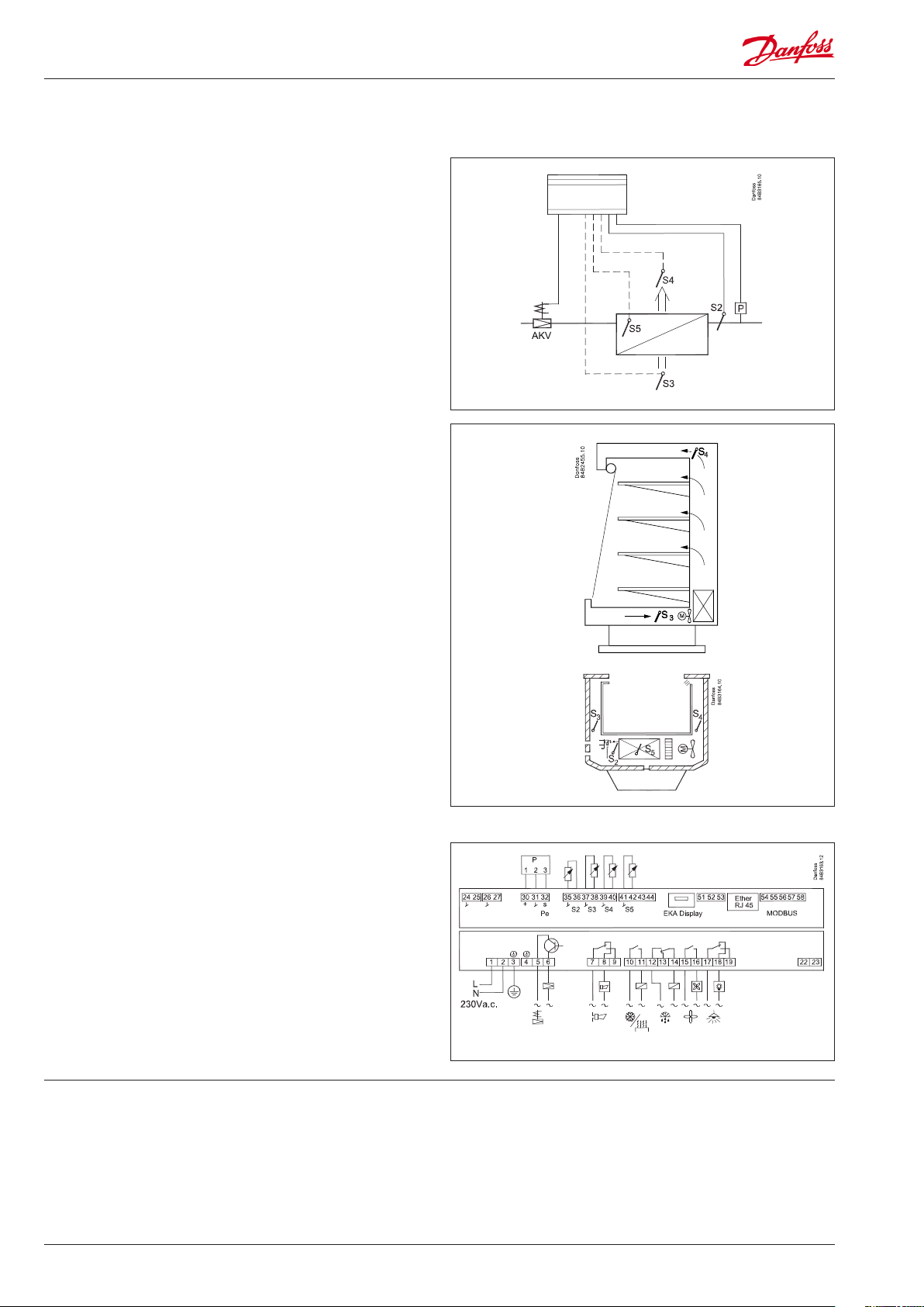
Connections
DI1 DI2
DO1 DO2 DO3 DO4 DO5 DO6 DI3
(od) (ALA) (CoP) (dEF) (FAn) (Lgt)
DI1
Digital input signal.
The defined function is active when the input is short-circuited/
opened. The function is defined in o02.
DI2
Digital input signal.
The defined function is active when the input is short-circuited/
opened. The function is defined in o37.
Pressure transmitter
AKS 32R
Connect to terminal 30, 31 and 32.
(Used cable 060G1034: Black=30, Blue=31, Brown=32)
The signal from one pressure transmitter can be received by up
to 10 controllers. But only if there are no significant pressure
decreases between the evaporators to be controlled.
S2
Pt 1000 ohm sensor
S3, S4, S5
Pt 1000 ohm sensor or PTC 1000 ohm sensor. All have to be of the
same type.
S3, air sensor, placed in the warm air before the evaporator
S4, air sensor, placed in the cold air after the evaporator
(the need for either S3 or S4 can be deselected in the
configuration)
S5, defrost sensor, placed on the evaporator.
EKA Display
If there is external reading/operation of the controller, display type
EKA 163B or EKA 164B can be connected.
RS485 (terminal 51, 52, 53)
For data communication, but only if a data communication
module is inserted in the controller. The module can be a LON
RS485, DANBUSS or a MODBUS.
Terminal 51 = screen
Terminal 52 = A (A+)
Terminal 53 = B (B-)
(For LON RS485 and gateway type AKA 245 the gateway must be
version 6.20 or higher.)
MODBUS
For data communication.
Terminal 56 = screen
Terminal 57 = A+
Terminal 58 = B(Alternatively the terminals can be connected to an external
display type EKA 163A or 164A, but then they cannot be used
for data communication. Any data communication must then be
carried out by one of the other methods.)
Supply voltage
230 V a.c., 50/60 Hz
DO1
Connection of expansion valve type AKV or AKVA. The coil must
be a 230 V a.c. coil.
DO2
Alarm
There is a connection between terminal 7 and 8 in alarm situations
and when the controller is without power.
DO3
Refrigeration or Rail heat
There is connection between terminal 10 and 11 when the
function must be active.
DO4
Defrost
There is connection between terminal 12 and 14 when defrosting
takes place.
DO5
Fan
There is connection between terminal 15 and 16 when the fan is
on.
DO6
Light
There is connection between terminal 17 and 18 when the light
must be on.
DI3
Digital input signal.
The signal must have a voltage of 0 / 230 V a.c..
The function is defined in o84.
24 Manual RS8HB302 © Danfoss 2016-07 AK-CC 525A

Data communication
If data communication is used, it is important that the installation
of the data communication cable is performed correctly.
See separate literature No. RC8AC…
Electric noise
Cables for sensors, DI inputs and data communication must be
kept separate from other electric cables:
- Use separate cable trays
- Keep a distance between cables of at least 10 cm
- Long cables at the DI input should be avoided
Installation considerations
Accidental damage, poor installation, or site conditions, can give
rise to malfunctions of the control system, and ultimately lead to a
plant breakdown.
Every possible safeguard is incorporated into our products to
prevent this. However, a wrong installation, for example, could still
present problems. Electronic controls are no substitute for normal,
good engineering practice.
Danfoss will not be responsible for any goods, or plant components, damaged as a result of the above defects. It is the installer's
responsibility to check the installation thoroughly, and to fit the
necessary safety devices.
Special reference is made to the necessity of signals to the
controller when the compressor is stopped and to the need of
liquid receivers before the compressors.
Your local Danfoss agent will be pleased to assist with further
advice, etc.
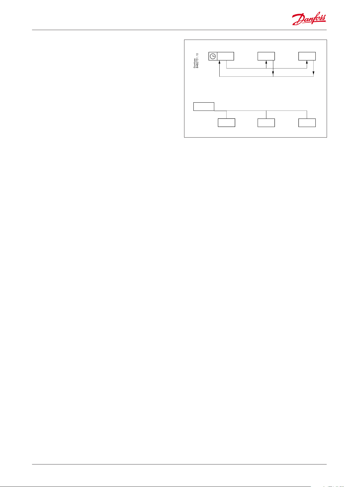
Coordinated defrost via
cable connections
Coordinated defrost via
data communication
Max. 10
The following controllers can be connected
up in this way:
EKC 204A, AK-CC 210, AK-CC 250,
AK-CC 450, AK-CC 550A,
Refrigeration is resumed when all
controllers have “released” the signal for
defrost.
The setting of controllers to coordinate
their defrosting takes place in the
gateway/system manager.
Refrigeration is resumed when all
controllers have “released” the signal for
defrost.
AK-CC 525A Manual RS8HB302 © Danfoss 2016-07 25

Data
Supply voltage 230 V a.c. (115 V a.c.) +10/-15 %. 5 VA, 50/60 Hz
Sensor S2 Pt 1000
Sensor S3, S4, S5
Accuracy
Measuring of Pe
External display EKA 163B or 164B (any EKA 163A or 164A)
Digital inputs
DI1, DI2
Digital input DI3 230 V a.c.
Electrical connection cable
Solid state
output
Relays*
Environments
Density IP 20
Mounting DIN-rail or wall
Weight 0.4 Kg
Data
communication
Power reserve
for the clock
Approvals
Pt 1000 or
PTC 1000 ohm
(All 3 must be of the same type)
Measuring range -60 to +120°C
Controller
Pt 1000 sensor
Pressure
transmitter
Signal from contact functions
Requirements to contacts: Gold plating
Cable length must be max. 15 m
Use auxiliary relays when the cable is longer
Max.1.5 mm2 multi-core cable
DO1
(for AKV coil)
DO3, DO4 4 (3) A
DO2, DO5, DO6 4 (3) A
0 to +55°C, During operations
-40 to +70°C, During transport
20 - 80% Rh, not condensed
No shock influence / vibrations
Fixed MODBUS
Extension options
The controller cannot be hooked up with a monitoring unit type m2.
4 hours
EU Low Voltage Directive and EMC demands re CEmarking complied with
LVD tested acc. EN 60730-1 and EN 60730-2-9, A1, A2
EMC tested acc. EN 61000-6-2 and EN 61000-6-3
UL file no. E31024
±1 K below -35°C
±0.5 K between -35 to +25°C
±1 K above +25°C
±0.3 K at 0°C
±0.005 K per grad
AKS 32R
Max. 240 V a.c. , Min. 28 V a.c.
Max. 0.5 A
Leak < 1 mA
Max. 1 pcs. AKV (2 pcs. if EEC coils
are used)
CE
(250 V a.c.)
UL**
(240 V a.c.)
4 A Resistive
3 FLA, 18 LRA
4 A Resistive
3 FLA, 18 LRA
LON RS485
MODBUS
DANBUSS
AKV info !!
(115 V a.c.)
230 V a.c. coil
(115 V a.c.)
AKS 32R info
(only 230 V version))
* DO3 and DO4 are 16 A relays. DO2, DO5 and DO6 are 8 A relays. Max. load must be observed.
**) UL-approval based on 30000 couplings.
The signal from one pressure transmitter can
be received by up to ten controllers.
Capacitive load
The relays cannot be used for the direct connection of capacitive loads
such as LEDs and on/off control of EC motors.
All loads with a switch mode power supply must be connected with a suitable contactor or similar.
There cannot be a significant drop in pressure
between the pressure transmitter’s position in
the suction line and the S2 temperature in the
individual evaporators.
26 Manual RS8HB302 © Danfoss 2016-07 AK-CC 525A

Ordering
Type Function Supply Code no.
AK-CC 525A
Case controller with MODBUS data communication
with connection plugs
Case controller with MODBUS data communication
without connection plugs (industrial pack 12 pcs.)
Case controller with MODBUS data communication
with connection plugs
Bag with 12 set connection plugs 084B8162
230 V
115 V 084B8017
084B8019
084B8119
EKA 175
EKA 178B Data communication module MODBUS 084B8571
EKA 176 Data communication module DANBUSS for Gateway 084B8583
EKA 176A Data communication module DANBUSS for AK-PI 200 084B8591
EKA 163B External display with plug for direct connection 084B8574
EKA 164B
EKA 163A External display with screw terminals 084B8562
EKA 164A External display with operation buttons and screw terminals 084B8563
Data communication module
LON RS 485
External display with operation buttons and plug for direct connections
084B8579
084B8575
Order examples:
Installation Data communication Connection Code no.
MODBUS 084B8019 (AK-CC 525A)
LON 084B8019
DANBUSS (gateway connection) 084B8019
MODBUS 084B8019
L
L < 15 m
L
LON / DANBUSS 084B8019
MODBUS / LON / DANBUSS 084B8019
084B8579
084B8583
084B8574 (Display)
084B7299 (Cable, 6 m)
084B8574 (Display)
084B7299 (Cable, 6 m)
084Bxxxx (Data module)
084B8562 (Display)
084Bxxxx (Data module)
L > 15 m
AK-CC 525A Manual RS8HB302 © Danfoss 2016-07 27

Danfoss can accept no responsibility for possible errors in catalogues, brochures and other printed material. Danfoss reserves the right to alter its products without notice. This also applies to products
already on order provided that such alternations can be made without subsequential changes being necessary in specifications already agreed.
All trademarks in this material are property of the respecitve companies. Danfoss and Danfoss logotype are trademarks of Danfoss A/S. All rights reserved.
28 Manual RS8HB302 © Danfoss 2016-07 AK-CC 525A
ADAP-KOOL®
 Loading...