

Installation Guide
AK-CC 460
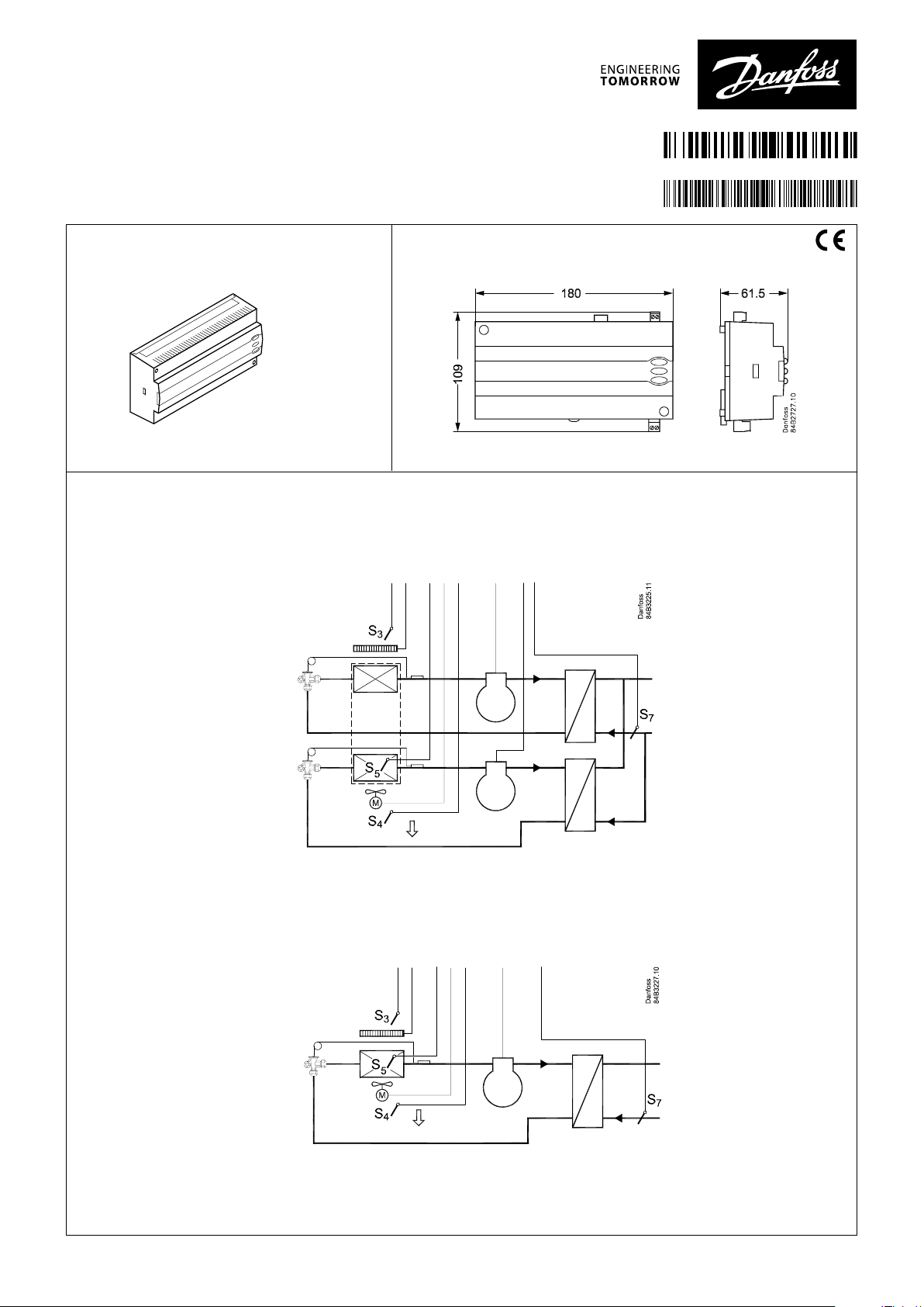
Identification
Principle
Application 1, 3
1: Sequential operation
3: Cyclic operation
084R8052
AN234086440123en-000301
Dimensions
08 4B8016
Application 2
Speed control
© Danfoss | DCS (vt) | 2019.08
AN234086440123en-000301 | 1
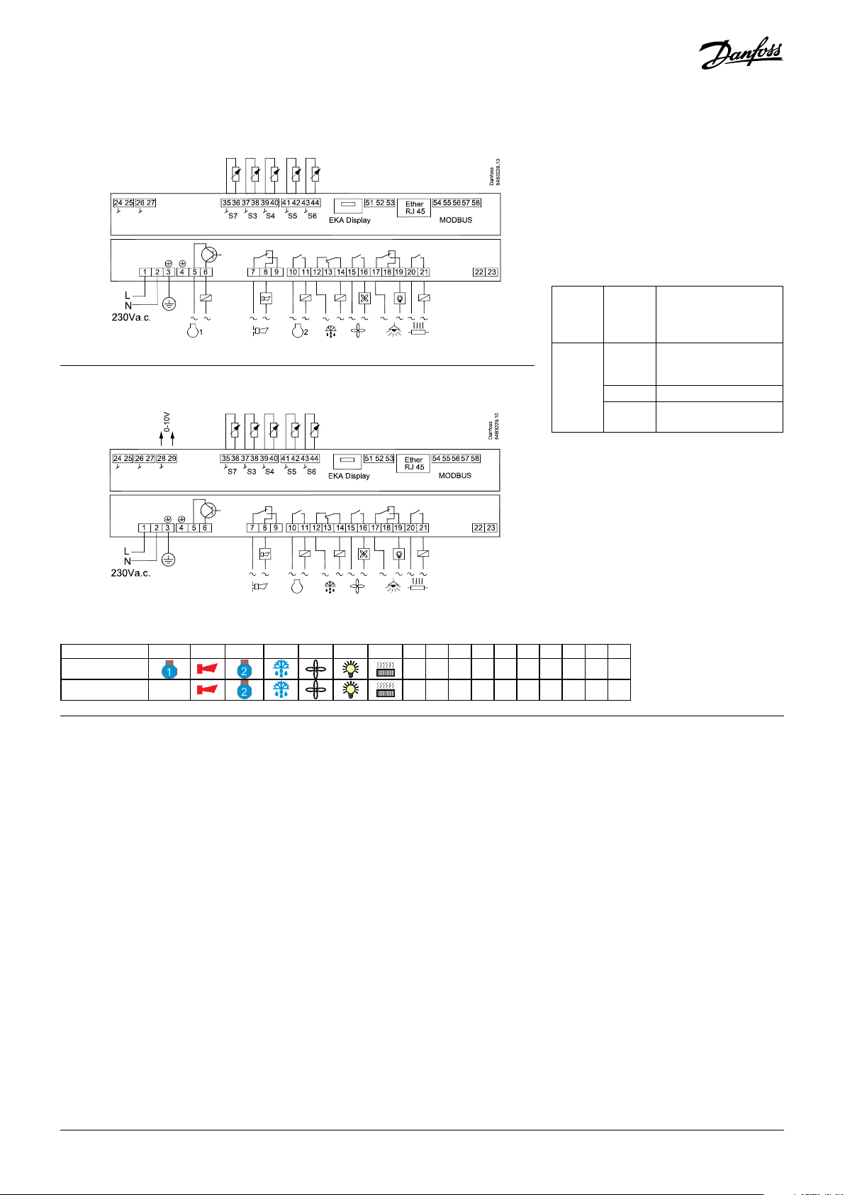
Connections
Appplication 1 and 3
DI1 DI2
Solid state
output
DO1 DO2 DO3 DO4 DO5 DO6 DO7 DI3
Appplication 2
DI1 DI2 AO
DO2 DO3 DO4 DO5 DO6 DO7 DI3
Overview of outputs and applications
Application DO1 DO2 DO3 DO4 DO5 DO6 DO7 DI1 DI2 DI3 AI1 AI2 AI3 AI4 AI5 AI6 AO
1 and 3
2
• • •
• • •
S7 S3 S4 S5 S6
S7 S3 S4 S5 S6 0-10V
Relays
DO1
(for coil)
DO3, DO4 4 (3) A
DO2, DO5,
DO6, DO7
Max. 240 V AC , Min. 28 V AC
Max. 0.5 A
Leak < 1 mA
Max. 1 pcs. coil
CE
(250 V AC)
IBExU approved
4 (3) A
DI1
Digital input signal.
The defined function is active when the input is short-circuited/
opened. The function is defined in o02.
DI2
Digital input signal.
The defined function is active when the input is short-circuited/
opened. The function is defined in o37.
AO
Analogue output (only application 2)
0 - 10 V signal for compressor speed control.
S7, S3, S4, S5, S6
Pt 1000 ohm
S7, brine sensor, placed in the cold inlet before the heat exchanger
S3, air sensor, placed in the warm air before the evaporator
S4, air sensor, placed in the cold air after the evaporator
(the need for either S3 or S4 can be deselected in the
configuration)
S5, defrost sensor, placed on the evaporator
S6, product sensor
2 | AN234086440123en-000301
EKA Display
If there is a need for external reading/operation of the controller,
display type EKA 163B or EKA 164B can be connected.
RS485 (terminal 51, 52, 53)
For data communication, but only if a data communication
module is inserted in the controller. The module can be a LON
RS485, DANBUSS or a MODBUS.
Terminal 51 = screen
Terminal 52 = A (A+)
Terminal 53 = B (B-)
(For LON RS485 and gateway type AKA 245, the gateway must be
version 6.20 or higher.)
RJ45
For data communication, but only if a TCP/IP module is inserted in
the controller. (OEM)
MODBUS
For data communication.
Terminal 56 = screen
Terminal 57 = A+
Terminal 58 = B(Alternatively the terminals can be connected to an external
display type EKA 163A or 164A, but then they cannot be used
© Danfoss | DCS (vt) | 2019.08
for data communication. Any data communication must then be
carried out by one of the other methods.)
Supply voltage
230 V AC, 50/60 Hz
DO1
Compressor 1 (only application 1 and 3)
Connection of relay. The coil must be a 230 V AC coil.
DI3
Digital input signal
Safety circuits compressor 1 and 2
The signal must have a voltage of 0 / 230 V AC
Data communication
If data communication is used, it is important that the installation
of the data communication cable is performed correctly.
See separate literature No. RC8AC…
DO2
Alarm
There is a connection between terminal 7 and 8 in alarm
situations and when the controller is without power.
DO3
Compressor 2
There is connection between terminal 10 and 11 when the
compressor is on.
DO4
Defrost
There is connection between terminal 12 and 14 when
defrosting takes place.
DO5
Fan
There is connection between terminal 15 and 16 when the fan
is on.
DO6
Light relay
There is connection between terminal 17 and 18 when the light
must be on.
DO7
Rail heat
There is connection between terminal 20 and 21 when the rail
heat is on.
Electric noise
Cables for sensors, DI inputs and data communication must be
kept separate from other electric cables:
- Use separate cable trays
- Keep a distance between cables of at least 10 cm
- Long cables at the DI input should be avoided
Installation considerations
Accidental damage, poor installation, or site conditions, can give
rise to malfunctions of the control system, and ultimately lead to a
plant breakdown.
Every possible safeguard is incorporated into our products to
prevent this. However, a wrong installation, for example, could
still present problems. Electronic controls are no substitute for
normal, good engineering practice.
Danfoss wil not be responsible for any goods, or plant
components, damaged as a result of the above defects. It is the
installer's responsibility to check the installation thoroughly, and
to fit the necessary safety devices.
Special reference is made to the necessity of signals to the
controller when the compressor is stopped and to the need of
liquid receivers before the compressors.
Your local Danfoss agent will be pleased to assist with further
advice, etc.
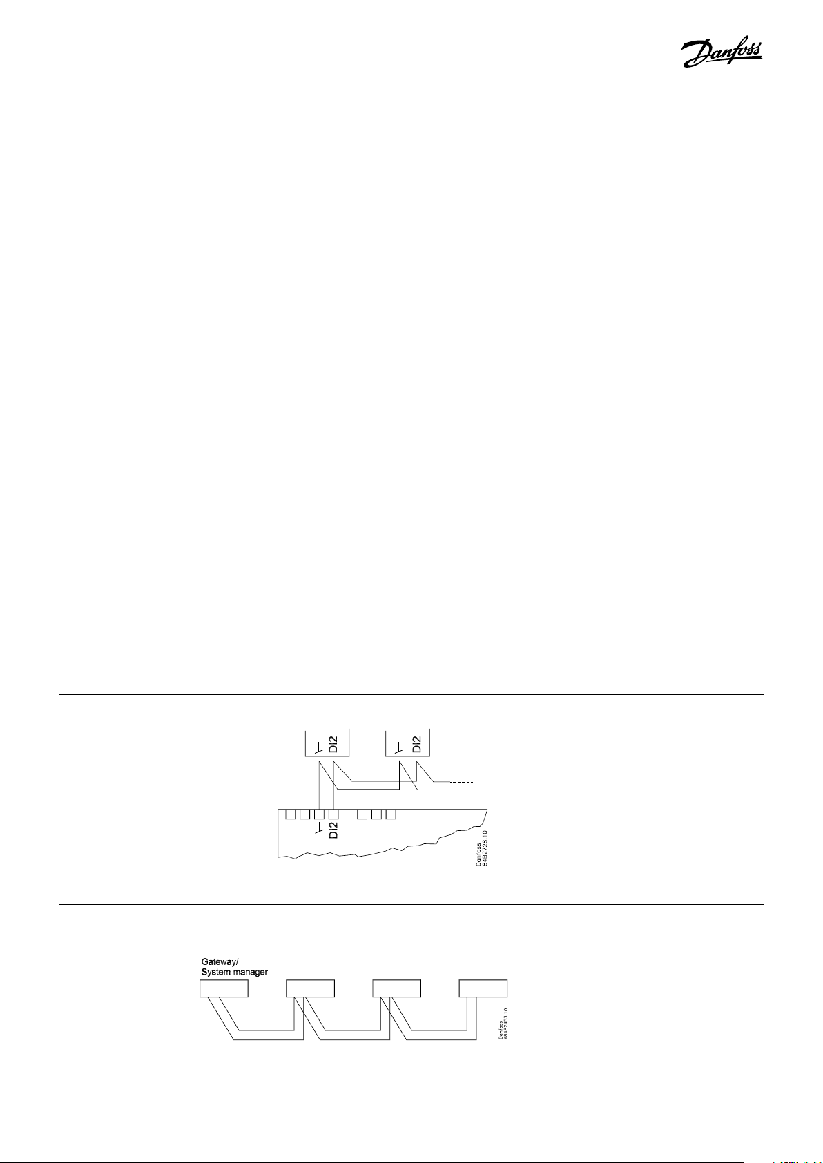
Coordinated defrost via
max. 10
cable connections The following controllers can be connected
up in this way:
EKC 204A, AK-CC 210, AK-CC 250,
AK-CC 450, AK-CC 460, AK-CC 550, AK-CC 55.
Refrigeration is resumed when all
controllers have “released” the signal for
defrost.
Coordinated defrost via
data communication
The setting of controllers to coordinate
their defrosting takes place in the gateway/
system manager.
Refrigeration is resumed when all controllers
have “released” the signal for defrost.
© Danfoss | DCS (vt) | 2019.08
AN234086440123en-000301 | 3

Data communication
AK-CC 450/550
AK-CC 460
Important All connections to the data communication MODBUS, RS 485 and DANBUSS
must comply with the requirements for data communication cables. See
literature: RC8AC.
System manager /
Gateway
Display EKA 163 / 164
L < 15 m
L > 15 m
AK-SM.... AKA 245 version 6.20+ /
AK-SM...
OEM
4 | AN234086440123en-000301
© Danfoss | DCS (vt) | 2019.08

Operation
Controller/Display
The values will be shown with three digits, and with a setting
you can determine w hether the temperature is to be shown i n
°C or °F.
Light-emitting diodes (LED) on front panel
The LEDs on the front panel will light up when the relevant relay
is activated.
= Refrigeration
= Defrost
= Fan running
The light-emitting diodes will flash when there is an alarm.
In this situation you can download the error code to the display
and cancel/accept the alarm by giving the top button a brief push.
The buttons
When you want to change a setting, the upper and the lower
buttons will give you a higher or lower value depending on the
button you are pushing. But before you change the value, you
must have access to the menu. You obtain this by pushing the
upper button for a couple of sec.onds - you will then enter the
column with parameter codes. Find the parameter code you
want to change and push the middle button until value for the
parameter is shown. When you have changed the value, save the
new value by once more pushing the middle button.
Get a good start
With the following procedure you can start regulation very
quickly:
1 Open parameter r12 and stop the regulation (in a new and not
previously set unit, r12 will already be set to 0 which means
stopped regulation).
2 Select electrical connection based on the drawings on page 2.
3 Open parameter o61 and set the electric connection number.
4 Open parameter r12 and start the regulation.
5 Go through the survey of factory settings. Make any necessary
changes in the respective parameters.
6 For network. Set the address in o03.
7 Send address to system unit:
• MODBUS: Activate scan function in system unit
• If another data communication card is used in the controller:
- LON RS485: Activate the function o04
Examples
Set menu
1. Push the upper button until a parameter r01 is shown
2. Push the upper or the lower button and find the parameter you
want to change
3. Push the middle button until the parameter value is shown
4. Push the upper or the lower button and select the new value
5. Push the middle button again to set the value.
Cut-out alarm relay / receipt alarm/see alarm code
• A short press of the upper button.
If there are several alarm codes they are found in a rolling stack.
Push the uppermost or lowermost button to scan the rolling
stack.
Set temperature
1. Push the middle button until the temperature value is shown
2. Push the upper or the lower button and select the new value
3. Push the middle button again to conclude the setting.
Reading the temperature at defrost sensor (or product sensor, if
selected in o92.)
• A short press of the lower button.
Manual start or stop of a defrost
• Push the lower button for four seconds.
© Danfoss | DCS (vt) | 2019.08
AN234086440123en-000301 | 5

Menu survey
Parameter wiring diagram
Function Code 1 & 3 2
Normal operation
Temperature (setpoint)
Thermostat
Differential
Max. limitation of setpoint setting
Min. limitation of setpoint setting
Adjustment of temperature indication
Temperature unit ( °C/°F)
Correction of the signal from S4
Correction of the signal from S3
Manual service, stop regulation, start regulation (-1, 0, 1)
Displacement of reference during night operation
Thermostat function (readout) 1= ON/OFF, 2=modulating
Definition and weighting, if applicable, of thermostat sensors - S4%
(100%=S4, 0%=S3)
Time between melt periods r16 1 1 0 hrs 10 hrs 1
Duration of melt periods r17 1 1 0 min. 30 min. 5
Temperature setting for thermostat band 2 . As differential r01 is used
Correction of the signal from S6 r59 1 1 -10 K 10 K 0
Definition and weighting, if applicable, of thermostat sensors when night
cover is on. (100%=S4, 0%=S3)
S4 min. limit, frost protection. Cooling is stopped.
Alarm settings
Delay for temperature alarm
Delay for door alarm
Delay for temperature alarm after defrost
High alarm limit for thermostat 1
Low alarm limit for thermostat 1
High alarm limit for thermostat 2
Low alarm limit for thermostat 2
High alarm limit for sensor S6 at thermostat 1
Low alarm limit for sensor S6 at thermostat 1
High alarm limit for sensor S6 at thermostat 2
Low alarm limit for sensor S6 at thermostat 2
S6 alarm time delay
With setting = 240 the S6 alarm will be omitted
Alarm time delay or signal on the DI1 input
Alarm time delay or signal on the DI2 input
Signal for alarm thermostat. S4% (100%=S4, 0%=S3)
Delay for S6 (product sensor alarm) after defrost
Alarm limit for max. S7 brine temperature
Differential for S7 brine alarm
Compressor
Min. ON-time
Min. OFF-time
Time delay for cut-in of comp.2
Compressor min. speed
Compressor start speed. Must be set higher than "Min. speed"
Compressor max. speed
KP for compressor PI control
Tn for compressor PI control
- - - 1 1 -50 °C 50 °C 2
r01 1 1 0.1 K 20 K 2
r02 1 1 -49 °C 50 °C 50
r03 1 1 -50 °C 49 °C -50
r04 1 1 -10 10 0
r05 1 1 0/ °C 1/F 0/ °C
r09 1 1 -10 K 10 K 0
r10 1 1 -10 K 10 K 0
r12 1 1 -1 1 0
r13 1 1 -50 K 50 K 0
r14 1 1 — — —
r15 1 1 0 % 100 % 100
r21 1 1 -50 °C 50 °C 2
r61 1 1 0 % 100 % 100
r98 1 1 -50 °C 20 °C -50 °C
A03 1 1 0 min. 240 min. 30
A04 1 1 0 min. 240 min. 60
A12 1 1 0 min. 240 min. 90
A13 1 1 -50 °C 50 °C 8
A14 1 1 -50 °C 50 °C -30
A20 1 1 -50 °C 50 °C 8
A21 1 1 -50 °C 50 °C -30
A22 1 1 -50 °C 50 °C 8
A23 1 1 -50 °C 50 °C -30
A24 1 1 -50 °C 50 °C 8
A25 1 1 -50 °C 50 °C -30
A26 1 1 0 min. 240 min. 240
A27 1 1 0 min. 240 min. 30
A28 1 1 0 min. 240 min. 30
A36 1 1 0 % 100 % 100
A52 1 1 0 min. 240 min. 90
A76 1 1 -50 °C 50 °C 8 °C
A77 1 1 0.1 K 10 K 3.0 K
c01 1 1 0 min. 30 min. 0
c02 1 1 0 min. 30 min. 0
c05 1 0 sec. 999 sec. 5
c46 1 25 Hz 70 Hz 30
c47 1 30 Hz 70 Hz 50
c48 1 50 Hz 100 Hz 100
c82 1 3 30 20
c83 1 30 sec. 360 sec. 60
Min.
value
Max.
value
Factory
setting
SW = 1.2x
Actual
setting
6 | AN234086440123en-000301
© Danfoss | DCS (vt) | 2019.08

Continued Code wiring diagram Min. Max. Fac. Actual
Compressor on time when sensor fault
Compressor off time when sensor fault
Compressor speed at sensor error
Max. sloperate (max. allowed change of speed per sec..)
Max Proportional factor Kp for PI control
Defrost
Defrost method: 0=none, 1= EL
Defrost stop temperature
Interval between defrost starts
Max. defrost duration
Displacement of time on cut-in of defrost at start-up
Drip off time
Delay for fan start after defrost
Fan start temperature
Fan cut-in during defrost
0: stopped
1 & 2: Running
Defrost sensor: 0 =Stop on time, 1=S5, 2=S4, 3=S5 and S6
Pump down delay
Max. aggregate refrigeration time between two defrosts
Rail heat during defrost
0: off
1: on
2: pulsing
Max. duration of -d- in display
Fan
Fan stop temperature (S5)
Pulse operation on fans: 0=No pulse operation, 1=At thermostat cut outs
only, 2= Only at thermostat cut-outs during night operation
Cycle time for fan pulsation (on-time + off-time)
On-time in % of cycle time
Real time clock
Six start times for defrost.
Setting of hours.
0=OFF
Six start times for defrost.
Setting of minutes.
0=OFF
Clock - Setting of hours
Clock - Setting of minutes
Clock - Setting of date
Clock - Setting of months
Clock - Setting of years
Miscellaneous
Delay of output signals after power failure
Input signal on DI1. Function:
0=not used. 1=status on DI1. 2=door function with alarm when open.
3=door alarm when open. 4=defrost start (pulse signal). 5=ext.main
switch. 6=night operation 7=thermostat band changeover (activate r21).
8=alarm function when closed. 9=alarm function when open. 10=case
cleaning (pulse signal). 12=night cover. 15=appliance shutdown
Network address (0= off)
On/Off switch (Service Pin message)
IMPORTANT! o61 must be set prior to o04
(used at LON 485 only)
c86 1 0 min 240 min 15
c87 1 0 min. 240 min. 15
c93 1 25 Hz 100 Hz 60
c96 1 0.1 Hz/s 5 Hz/s 1
n95 1 5 50 20
d01 1 1 0/No 1/EL 1/EL
d02 1 1 0 °C 50 °C 6
d03 1 1 0 hrs/Off240 hrs 8
d04 1 1 0 min. 360 min. 45
d05 1 1 0 min. 240 min. 0
d06 1 1 0 min. 60 min. 0
d07 1 1 0 min. 60 min. 0
d08 1 1 -50 °C 0 °C -5
d09 1 1 0 2 1
d10 1 1 0 3 0
d16 1 0 min. 60 min. 0
d18 1 1 0 hrs 48 hrs 0/OFF
d27 1 1 0 2 2
d40 1 1 5 min. 240 min. 30
F04 1 1 -50 °C 50 °C 50
F05 1 1 0 2 0
F06 1 1 1 min. 30 min. 5
F07 1 1 0 % 100 % 100
t01 t06
t11 t16
t07 1 1 0 hrs 23 hrs 0
t08 1 1 0 min. 59 min. 0
t45 1 1 1 day 31 days 1
t46 1 1 1 mon. 12 mon. 1
t47 1 1 0 year 99 years 0
o01 1 1 0 sec. 600 sec. 5
o02 1 1 0 15 0
o03 1 1 0 240 0
o04 1 1 0/Off 1/On 0/Off
1 1 0 hrs 23 hrs 0
1 1 0 min. 59 min. 0
© Danfoss | DCS (vt) | 2019.08
AN234086440123en-000301 | 7

Continued Code wiring diagram Min. Max. Fac. Actual
Access code 1 (all settings)
Software Version
Mains frequency
Max. hold time after coordinated defrost
Select signal for display view. S4% (100%=S4, 0%=S3)
Input signal on DI2. Function:
0=not used. 1=status on DI2. 2=door function with alarm when open.
3=door alarm when open. 4=defrost start (pulse signal). 5=ext. main
switch 6=night operation 7=thermostat band changeover (activate
r21). 8=alarm function when closed. 9=alarm function when open.
10=case cleaning (pulse signal). 12=night cover, 13=coordinated defrost.
15=appliance shutdown
Configuration of light function: 1=light follows day /night operation,
2=light control via data communication via ‘o39’, 3=light control with a
DI-input, 4=as "2", but light switches on and night cover will open if the
network cuts out for more than 15 minutes.
Activation of light relay (only if o38=2) On=light
Rail heat On time during day operations
Rail heat On time during night operations
Rail heat cycle time (On time + Off time)
Case cleaning. 0=no case cleaning. 1=fans only. 2=all output Off.
Selection of wiring diagram. See overview page 2.
1=Two compressors controlled sequentially
2= One compressor speed controlled
3= Two compressors controlled cyclic
Access code 2 (partial access)
Replace the controller's factory settings with the present settings
Rail heat control
0=not used, 1=pulse control with timer function (o41 and o42), 2=pulse
control with dew point function
Dew point value where the rail heat is minimum
Dew point value where the rail heat is 100% on
Lowest permitted rail heat effect in %
Time delay from "open door” refrigeration is started
Definition of readings on lower button:
1=defrost stop sensor, 2=S6 sensor
Display of temperature
1= u56 air temperature
2= u36 product temperature
Light and night blinds defined:
0: Light is switched off and night blind is opened when the main switch is off
1: Light and night blind are independent of main switch
Configuration of alarm relay
The alarm relay will be activated upon an alarm signal from the following
groups:
1 - High temperature alarms
2 - Low temperature alarms
4 - Sensor error
8 - Digital input is activated for alarm
16 - Defrost alarms
32 - Miscellaneous
The groups that are to activate the alarm relay must be set by using a
numerical value which is the sum of the groups that must be activated.
(E.g. a value of 5 will activate all high temperature alarms and all sensor
errors).
0 = Cancel relay function
Stop time for fan while night blind rolls down P65 1 1
o05 1 1 0 100 0
o08 1 1
o12 1 50 Hz 60 Hz 50
o16 1 1 0 min. 360 min. 20
o17 1 1 0 % 100 % 100
o37 1 1 0 15 0
o38 1 1 1 4 1
o39 1 1 0/Off 1/On 0/Off
o41 1 1 0 % 100 % 100
o42 1 1 0 % 100 % 100
o43 1 1 6 min. 60 min. 10
*** o46 1 1 0 2 0
* o61 1 1 1 3 1
*** o64 1 1 0 100 0
o67 1 1 0/Off 1/On 0/Off
o85 1 1 0 2 0
o86 1 1 -10 °C 50 °C 8
o87 1 1 -9 °C 50 °C 17
o88 1 1 0 % 100 % 30
o89 1 1 0 min. 240 min. 30
o92 1 1 1 2 1
o97 1 1 1 2 1
o98 1 1 0 1 0
P41 1 1
0 63 47
0 min. 5 min. 0 min.
8 | AN234086440123en-000301
© Danfoss | DCS (vt) | 2019.08

Service
Temperature measured with S5 sensor
Status on DI1 input. on/1=closed
Actual defrost time (minutes)
Temperature measured with S3 sensor
Status on night operation (on or off) 1=on
Temperature measured with S4 sensor
Thermostat temperature
Run time of thermostat (cooling time) in minutes
Temperature measured with S6 sensor
(product temperature)
Status on DI2 output. on/1=closed
Readout the compressor capacity in %
Display air temperature. Weighted S3 + S4 (o17)
Measured temperature for alarm thermostat. Weighted S3 + S4 (A36)
Status on relay for compressor 1
Status on relay for fan
Status on relay for defrost
Status on relay for rail heat
Status on relay for alarm
Status on relay for light
Status on relay for compressor 2
Readout of the actual rail heat effect
1: Thermostat 1 operating, 2: Thermostat 2 operating
Status on high voltage input DI3
Readout of thermostat's actual cut-in value
Readout of thermostat's actual cut-out value
Readout of brine temperature S7 u98 1 1
Readout of voltage on AO output U44 1
*) Can only be set when regulation is stopped (r12=0)
**) Can be controlled manually, but only when r12=-1
***) With access code 2 the access to these menus will be limited
u09 1 1
u10 1 1
u11 1 1
u12 1 1
u13 1 1
u16 1 1
u17 1 1
u18 1 1
u36 1 1
u37 1 1
U52 1
u56 1 1
u57 1 1
** u58 1
** u59 1 1
** u60 1 1
** u61 1 1
** u62 1 1
** u63 1 1
** u67 1 1
u85 1 1
u86 1 1
u87 1 1
u90 1 1
u91 1 1
Forced control
If you need to force-control an output, you should set r12 to -1 (manual
mode). You should then select the relevant relay function, e.g. u58. Go to the
function by pressing the middle button. Select On.
© Danfoss | DCS (vt) | 2019.08
Factory setting
If you need to return to the factory-set values, it can be done in this way:
- Cut out the supply voltage to the controller.
- Keep upper and lower button depressed at the same time as you
reconnect the supply voltage.
Factory settings are indicated for standard units. Other code numbers
have customized settings.
AN234086440123en-000301 | 9

Fault message
In an error situation the LEDs on the front will flash and the alarm relay
will be activated. If you push the top button in this situation you can see
the alarm report in the display.
There are two kinds of error reports - it can either be an alarm occurring
during the daily operation, or there may be a defect in the installation.
A-alarms will not become visible until the set time delay has expired.
E-alarms, on the other hand, will become visible the moment the error
occurs.
(An A alarm will not be visible as long as there is an active E alarm).
Here are the messages that may appear:
Code / Alarm text via
data communication
A1/--- High t.alarm
A2/--- Low t. alarm
A4/--- Door alarm
A5/--- Max hold time
A13/--- High temp S6 Temperature alarm. High S6 1
A14/--- Low temp S6 Temperature alarm. Low S6 2
A15/--- DI1 alarm DI1 alarm 8
A16/--- DI2 alarm DI2 alarm 8
A45/--- Standby mode Standby position (stopped
A59/--- Case clean Case cleaning. Signal from DI
A97/--- Comp. Safety Compressor safety. Signal from
AA3/---High brine temp. High brine temperature alarm 8
E1/--- Ctrl. error Faults in the controller 32
E6/--- RTC error Check clock 32
E25/--- S3 error Error on S3 sensor 4
E26/--- S4 error Error on S4 sensor 4
E27/--- S5 error Error on S5 sensor 4
E28/--- S6 error Error on S6 sensor 4
E50/--- S7 error
---/--- Max Def.Time Defrost stopped based on
Data communication
The importance of individual alarms can be defined with a setting. The
setting must be carried out in the group "Alarm destinations"
Settings from
System manager AK-SM
High 1 X
Middle 2 X
Low 3 X
Log only
Disabled
Description Alarm
High temperature alarm
Low temperature alarm
Door alarm
The ”o16” function is activated
during a coordinated defrost
refrigeration via r12 or DI input)
input
DI3 input
Error on S7 sensor
time instead of, as wanted, on
temperature
Settings from
AKM (AKM destination)
relay
groups
(P41)
Send via
Network
1
2
8
16
-
-
8
4
16
Operating status
The controller goes through some regulating situations where it is just waiting for the next point
of the regulation. To make these “why is nothing
happening” situations visible, you can see an operating status on the display. Push briefly (1s) the
upper button. If there is a status code, it will be
shown on the display. The individual status codes
have the following meanings:
Normal regulation S0 0
Waiting for end of the coordinated defrost S1 1
When the compressor is operating it must run for
at least x minutes.
When the compressor is stopped, it must remain
stopped for at least x minutes.
The evaporator drips off and waits for the time to
run out
Refrigeration stopped by main switch. Either with
r12 or a DI-input
Refrigeration stopped by thermostat S11 11
Defrost sequence. Defrost in progress S14 14
Defrost sequence. Fan delay — water attaches to
the evaporator
Door is open. DI input is open S17 17
Melt function in progress. Refrigeration is interrupted
Modulating thermostat control S19 19
Emergency cooling due to sensor error *) S20 20
Manual control of outputs S25 25
Case cleaning S29 29
Delay on outputs during start-up S32 32
Case shutdown S45 45
Other displays:
The defrost temperature cannot be displayed.
There is stop based on time
Defrost in progress / First cooling after defrost -d-
Password required. Set password PS
Regulation is stopped via main switch OFF
*) Emergency cooling will take effect when there is lack of signal from a
defined S3 or S4 sensor. The regulation will continue with a registered
average cut-in frequency. There are two registered values – one for day
operation and one for night operation.
S2 2
S3 3
S4 4
S10 10
S15 15
S18 18
non
(Measurement)
Ctrl. state:
(Shown in
all menu
displays)
Additional information:
Manual RS8HS...
10 | AN234086440123en-000301
ADAP-KOOL®
© Danfoss | DCS (vt) | 2019.08
 Loading...