

User Guide
Controller for SemiPlugin appliance
AK-CC 460
www.danfoss.com
User Guide | Controller for SemiPlugin appliance, AK-CC 460
Contents
Introduction .........................................................................................................2
Applications .........................................................................................................3
Survey of functions ......................................................................................... 10
Operation ........................................................................................................... 21
Introduction
Application
Complete refrigeration appliance control for SemiPlugin
refrigeration appliances.
- Where condensation heat is removed using brine
- Flammable refrigerants supported
- The total amount of refrigerant can be distributed across more
circuits
- Variable speed compressor control
Advantages
• Energy optimisation of the whole refrigeration appliance
• One controller for several different refrigeration appliances
• Integrated display at the front of the controller
• Built-in data communication
• Built-in clock function with power reserve
Menu survey ...................................................................................................... 22
Connections ...................................................................................................... 26
Data ...................................................................................................................... 28
Ordering ............................................................................................................. 29
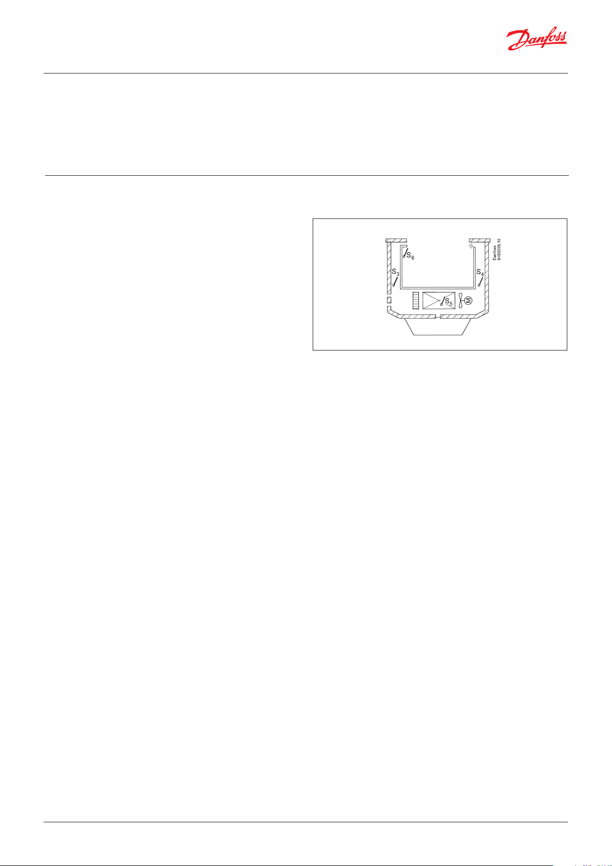
Principle
The temperature in the appliance is registered by one or two
temperature sensors which are located in the air flow before the
evaporator (S3) or after the evaporator (S4) respectively. A setting
for thermostat, alarm thermostat and display reading determines
the influence the two sensor values should have for each
individual function.
In addition product sensor S6, which can be optionally placed in
the appliance, can be used to register the temperature near the
required product in a certain place within the appliance.
The temperature of the evaporator is registered with the S5 sensor
which can be used as a defrosting sensor.
In addition to the output for the compressors, the controller has 5
relay outputs for dedicated applications.
Functions
• Day/night thermostat
• Product sensor S6 with separate alarm limits
• Switch between thermostat settings via digital input
• Start of defrost via schedule, digital input or network
• Natural or electric defrost
• Stop of defrost on time and/or temperature
• Coordination of defrost across several controls
• Pulsing of fans when thermostat is satisfied
• Case cleaning function for documentation of HACCP procedure
• Rail heat control via day/night load or dew point
• Door function
• Control of two compressors or one variable speed compressor
• Control of night blinds and light
• Factory calibration that will guarantee a better measuring
accuracy than stated in the standard EN ISO 23953-2 without
subsequent calibration (Pt 1000 ohm sensor)
• Integrated MODBUS communication with the option of
mounting a LonWorks or DANBUSS
2 | BC230086440483en-000201 © Danfoss | DCS (vt) | 2019.12
User Guide | Controller for SemiPlugin appliance, AK-CC 460
Applications
The controller supports the following 3 control modes:
- Sequential On/Off control of 2 compressors.
Output 1 will form the base load, and output 2 will connect a
lower capacity so that the variation of the cabinet temperature
is kept to a minimum.
The compressors are coupled sequentially. Compressor 1 is first
in and last out.
- Cyclic On/Off control of 2 compressors.
Here the compressors must be of equal size, and they are
coupled cyclic.
The runtimes are equalized.
- Variable speed control of one compressor
Here one compressor output is used together with the analogue
0 – 10 V signal.
Enables a very precise control of the cabinet temperature.
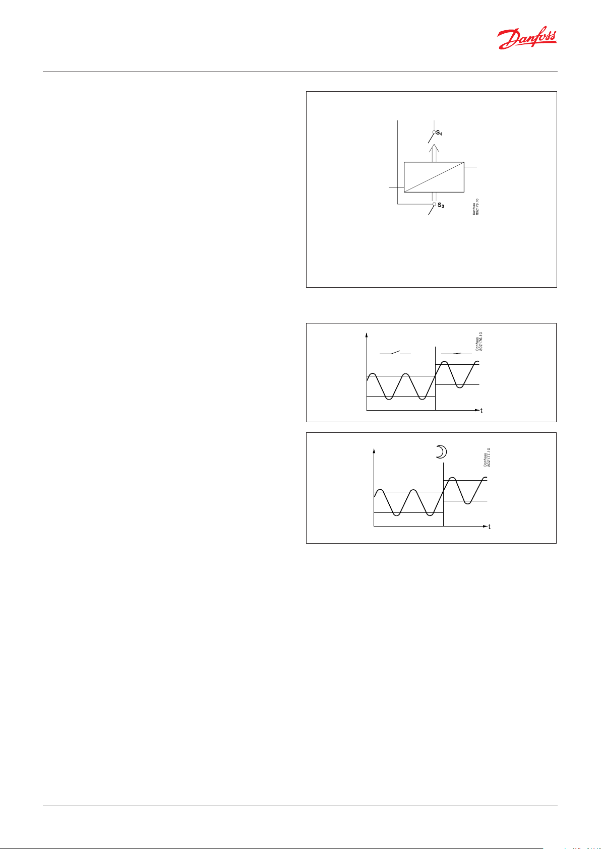
Control with two compressors
When the controller calls for refrigeration, compressor 1 will be
cutin to the circuit first.
After the delay time, compressor 2 will be coupled to the circuit.
When the temperature has reached the middle of the differential,
compressor 2 will be cut out.
Compressor 1 will continue until the temperature has reached the
cut-out value. Then it will cut out. When the temperature again
reaches the middle of the differential, compressor 1 will be cutin to
the circuit again.
If compressor 1 cannot maintain the temperature within the differential, compressor 2 will also be cutin to the circuit.
The compressor's settings for ”Min On time” and ”Min Off time”
will always have top priority during normal regulation. But if one
of the override functions is activated, the ”Min On time” will be
disregarded.
With cyclic control the compressor with the lowest runtime will be
started first.
If one of the compressors has been running continuously for
two hours, the compressors will be alternated to assure runtime
equalization.
Variable speed control
Here the compressor will be started when the controller requests
cooling.
The analogue output will then be used to control the speed so
that the temperature is kept very accurate at the reference.
The actual reference is the set cut-out temperature plus half the
set difference.
© Danfoss | DCS (vt) | 2019.12 BC230086440483en-000201 | 3
User Guide | Controller for SemiPlugin appliance, AK-CC 460
Temperature control
The temperature in the appliance is registered by one or two
temperature sensors which are located in the air flow before the
evaporator (S3) or after the evaporator (S4) respectively. A setting
for the thermostat, alarm thermostat and display reading determines how much the two sensor values should influence each
individual function, e.g. 50% will produce an equal value from
both sensors.
There are separate settings for day operation and night operation.
Temperature monitoring
Just as it is possible for the thermostat, the alarm monitoring can
be set with a weighting between S3 and S4 so that you can decide
how much the two sensor values should influence the alarm
monitoring. Minimum and maximum limits can be set for alarm
temperature and time delays. A longer time delay can be set for
high temperature alarms after defrosting, appliance cleaning or
start-up.
Thermostat bands
Thermostat bands can be used beneficially for appliances where
different product types are stored which require different temperature conditions. It is possible to change between the two
different thermostat bands via a contact signal on a digital input.
Separate thermostat and alarm limits can be set for each thermostat band – also for the product sensor.
Night setback of thermostat value
In refrigeration appliances there may be big load differences
between the shop’s opening and closing hours, especially if night
lids/blinds are used. The thermostat reference may be raised here
without it having any effect on the product temperature.
Change-over between day and night operation can take place, as
follows:
• via an external switch signal.
• via a signal from the data communication system.
Product sensor
A separate optional product sensor S6, which may be placed in the
appliance, can also be used and which can register and monitor
the temperature in the warmest part of the appliance. There are
separate alarm limits and time delays for the product sensor.
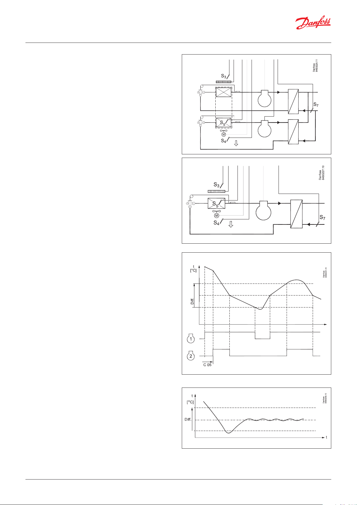
S7 brine sensor
The temperature at the brine inlet is monitored by the S7
temperature sensor. If the temperature gets higher than the set
value, the controller will reduce the cooling capacity, so that the
load on the heat exchanger is reduced.
For two-compressor operation, compressor 2 will be taken out of
operation.
With variable speed control the compressor speed will be reduced
to the value defined by parameter "c93".
4 | BC230086440483en-000201 © Danfoss | DCS (vt) | 2019.12
User Guide | Controller for SemiPlugin appliance, AK-CC 460
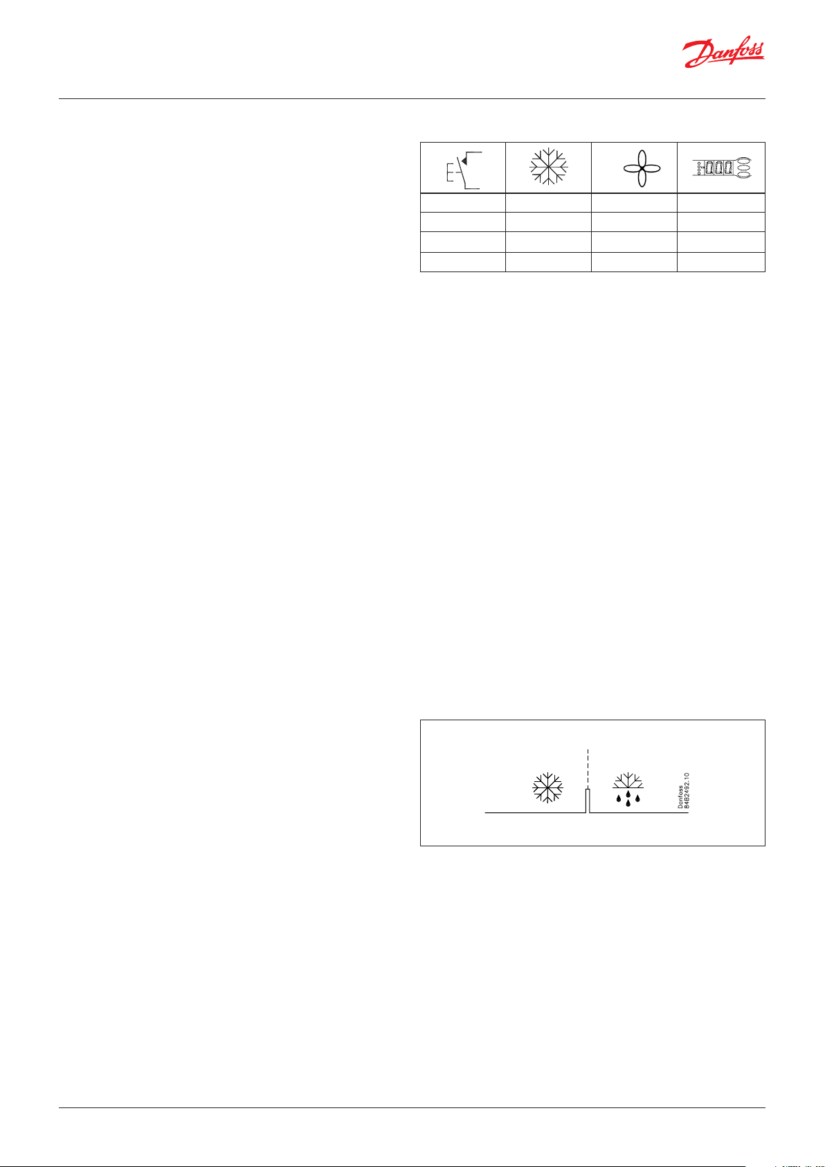
Appliance cleaning
This function makes it easy for the shop’s staff to carry out a
cleaning of the appliance according to a standard procedure.
Appliance cleaning is activated via a signal – as a rule via a key
switch placed on the appliance.
Appliance cleaning is carried out via three phases:
1 - at the first activation the refrigeration is stopped, but the fans
keep on operating in order to defrost the evaporators. ”Fan” is
shown on the display.
2 - at the second activation the fans are also stopped and the
appliance can now be cleaned. ”OFF” is shown on the display.
3 - At the third activation refrigeration is recommenced. The
display will show the actual appliance temperature (o97
setting).
Documentation
When appliance cleaning is activated a cleaning alarm is transmitted to the normal alarm recipient. A later processing of these
alarms will document that the appliance has been cleaned as
often as planned.
Alarm monitoring
There are no temperature alarms during appliance cleaning.
- + + °C
1 ÷ + Fan
2 ÷ ÷ Off
3 + + °C
Defrost
Depending on the application you may choose between the following defrost methods:
Natural: Here the fans are kept operating during the defrost
Electric: The heating element is activated
Defrost sequence
1) Defrost
2) Waiting position after defrost
3) Drip off
4) Delay of fan
Start of defrost
A defrost can be started in different ways
Interval: Defrost is started at fixed time intervals, say, every
eighth hour. An interval must ALWAYS be set to
a "higher" value than the period set between two
defrostings when a schedule or network signal is used.
Refrigeration time: Defrost is started at fixed refrigeration time
intervals, in other words, a low need for refrigeration will
”postpone” the defrost
Schedule: Here defrost can be started at fixed times of the
day and night. However, max. 6 times
Contact: Defrost is started with a contact signal on a digital input
Network: The signal for defrost is received from a system unit
via the data communication
Manual: An extra defrost can be activated from the controller’s
lower-most button
All the mentioned methods can be used at random – if any of
them is activated a defrost will be started.
Stop of defrost
Defrosting can be stopped by either:
• Time
• Temperature (with time as safety).
© Danfoss | DCS (vt) | 2019.12 BC230086440483en-000201 | 5
User Guide | Controller for SemiPlugin appliance, AK-CC 460
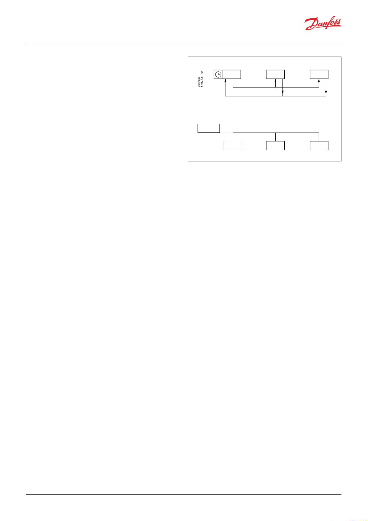
Coordinated defrost
There are two ways in which coordinated defrost can be arranged.
Either with wire connections between the controllers or via data
communication
Wire connections
The digital input DI2 is connected between the current controllers.
When one controller starts a defrost all the other controllers will
follow suit and likewise start a defrost. After the defrost the individual controllers will move into waiting position. When all are in
waiting position there will be a change-over to refrigeration.
Coordination via data communication
Here the system unit handles the coordination.
The controllers are gathered in defrosting groups and the system
unit ensures that defrosting is started in the group according to a
weekly schedule.
When a controller has completed defrosting, it sends a message
to the system unit and then goes into a waiting position. When
every controller in the group is in a waiting position, refrigeration
is again permitted in all the individual controllers.
Defrost on demand
Based on refrigeration time
When the aggregate refrigeration time has passed a fixed time, a
defrost will be started.
Max. 10
System manager
Melting function
This function will stop the air flow in the evaporator from being reduced by frost created by uninterrupted operation for a long time.
The function is activated if the thermostat temperature has
remained in the range between -5°C and +10°C for a longer
period than the set melting interval. The refrigeration will then be
stopped for the set melting period. The frost will be melted so that
the air flow and hence the evaporator’s capacity will be greatly
improved.
Real-time clock
The controller has a built-in real-time clock which can be used to
start defrosts. This clock has a power reserve of four hours.
If the controller is equipped with data communication, the clock
will automatically be updated from the system unit.
6 | BC230086440483en-000201 © Danfoss | DCS (vt) | 2019.12
AO
0 – 10
c46
c47
c48
80G437
User Guide | Controller for SemiPlugin appliance, AK-CC 460
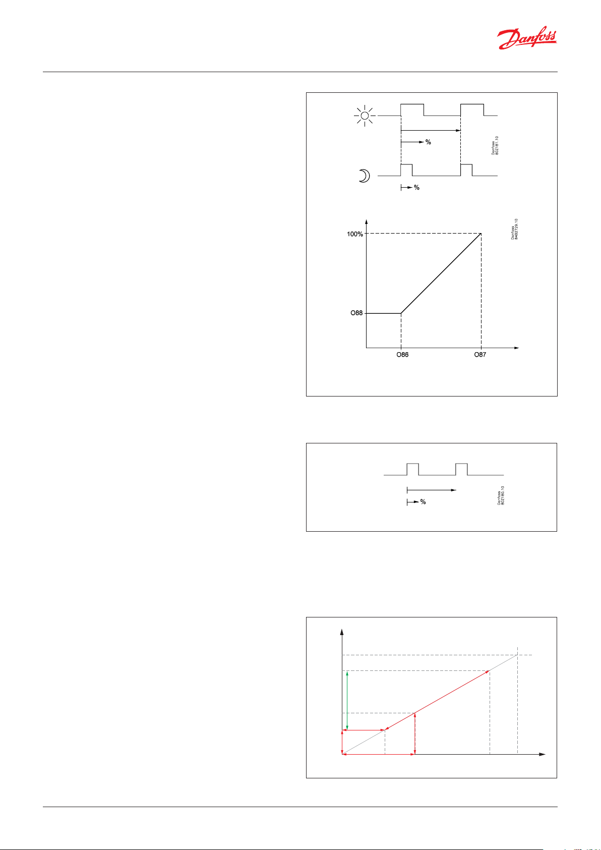
Railheat
It is possible to pulse-control the power to the rail heat in order to
save energy. Pulse control can either be controlled according to
day/night load or dew point.
Pulse control according to day and night
Various ON periods can be set for day and night operation.
A period time is set as well as the percentage part of the period in
which the rail heat is ON.
Pulse control according to dew point
In order to use this function a system manager of the type AK-SM
is required which can measure dew point and distribute the current dew point to the appliance controllers. For this the rail heat’s
ON period is controlled from the current dew point.
Two dew point values are set in the appliance control:
• One where the effect must be max. i.e.100%. (o87)
• One where the effect must be min. (o86).
At a dew point which is equal to or lower than the value in 086, the
effect will be the value indicated in o88.
In the area between the two dew point values the controller will
manage the power to be supplied to the rail heat.
During defrosting
During defrosting the rail heat will be controlled by the setting in
"d27" (Off, On or pulsing).
Fan
Pulse control
To obtain energy savings it is possible to pulse control the power
supply to the evaporator fans.
Pulse control can be accomplished in one of the following ways:
- during the thermostat’s cutout period (cold room)
- during night operation and during the thermostat’s cutout pe-
riod (appliance with night lid /blind)
Rail heat
Dew point
A period of time is set as well as the percentage of this period of
time where the fans have to be operating.
Cutout of fans during plant breakdowns
If the refrigeration in a breakdown situation stops, the temperature
in the refrigeration appliance may rise as a result of the power
supply from fans. In order to prevent this situation the controller
can stop the fans if the temperature at S5 exceeds a set limit value.
Variable speed compressor control
The variable speed compressor control is using these 3 settings:
- Start speed - c47. After starting the compressor, this speed will
be maintained for 10 seconds. Hereafter the speed can vary
between min. and max speed
- Max. speed – c48. The max allowed speed for the compressor
- Min. speed – c46. At low requested capacity, the set minimum
speed will be maintained until the compressor is cut out.
Note: the voltage on the analogue output is scaled for the
maximum frequency range from min. speed to 100 Hz, meaning
that if the max. speed is set lower than 100 Hz, the max. output
voltage will be below 10 V.
10 V
V Max.
V Start
V Min.
V
Active voltage range
Fmin
Fstart
Fmax
Danfoss
100 Hz
© Danfoss | DCS (vt) | 2019.12 BC230086440483en-000201 | 7

User Guide | Controller for SemiPlugin appliance, AK-CC 460
Light function
The function can be used for controlling the light in a refrigeration
appliance or in a coldroom. It can also be used for controlling a
motorised night blind.
The light function can be defined in three ways:
- the light is controlled via a signal from a door contact. Together
with this function a time delay can be set so that the light is kept
on for 2 minutes after the door has been closed.
- the light is controlled via the day/night function
- the light is controlled via the data communication from a system
unit.
Here there are two operational options if data communication
should fail:
- The light can go ON
- The light can stay in its current mode.
The light load must be connected to the NC switch on the relay.
This ensures that the light remains on in the appliance if power to
the controller should fail.
The light is switched off when "r12" (Main switch) is set to off (see
o98).
Night blind
Motorised night blind can be controlled automatically from the
controller. The night blinds will follow the status of the light
function. When the light is switched on, the night blinds opens
and when the light is switched off, the night blinds close again.
When the night blinds are closed, it is possible to open them and
switch on the light using a switch signal on the digital input. If this
input is activated, the night blinds will open and the refrigeration
appliance can be filled with new products. If the input is activated
again, the blinds close again.
A night blind is open and light is switch on when the appliance
cleaning function is activated.
A setting can define that the night blind is open when "r12" (Main
switch) is set to off (see o98).
When the night blind rolls down, the fans can be stopped so that
the air circulation does not interrupt the positioning of the blind.
The desired stop time must be set in P65.
The motor for the night blinds must be connected to the same
relay as the light function.
Digital inputs
There are two digital inputs DI1 and DI2 with contact function and
one digital input DI3 with high voltage signal.
DI1 and DI2 input can be used for the following functions:
- Retransmission of contacts position via data communication
- Door contact function with alarm
- Starting a defrost
- Main switch - start/stop of cooling
- Night setback
- Thermostat bands switch
- General alarm monitoring
- Case cleaning
- Override of night blinds
- Case shut down
- Coordinated defrost (DI2 only)
DI3 is predefined as input from the safety circuit for the
compressors. When the voltage on the input is interrupted, the
compressors will stop, and the alarm "A97 - Comp.Safety" will be
activated.
Door contact
The door contact function can via the digital inputs be defined for
two different applications:
Alarm monitoring
The controller monitors the door contact and delivers an alarm
message if the door has been opened for a longer period than
the set alarm delay.
Alarm monitoring and stop of refrigeration
When the door is opened the refrigeration is stopped and the
fan are stopped and light switch on.
If the door remains open for a longer time than the set restart
time, refrigeration will be resumed. This will ensure that
refrigeration is maintained even if the door is left open or if the
door contact should be defective. If the door remains open for
a longer period than the set alarm delay an alarm will also be
triggered.
8 | BC230086440483en-000201 © Danfoss | DCS (vt) | 2019.12
User Guide | Controller for SemiPlugin appliance, AK-CC 460
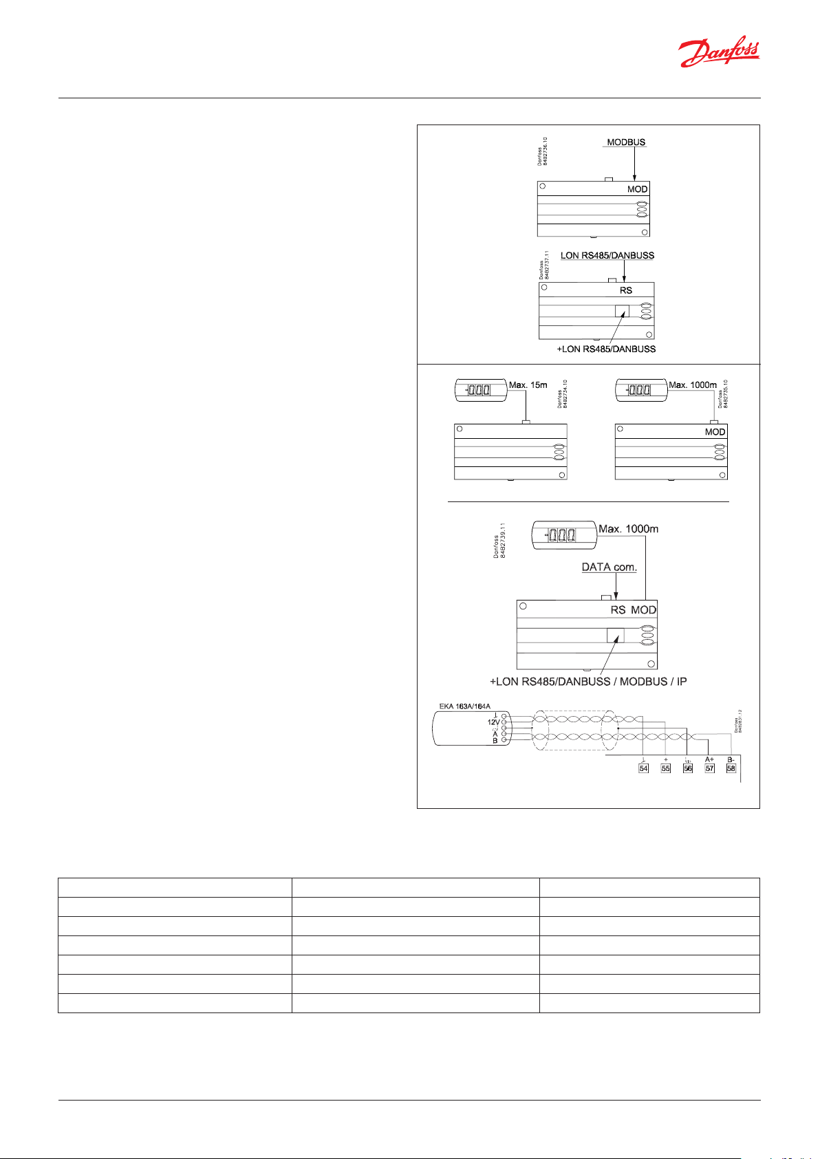
Data communication
The controller has fixed built-in MODBUS data communication.
If there is a requirement for a different form of data
communication, a Lon RS 485 or DANBUSS module can be inserted
in the controller.
The connection must then be to terminal RS 485.
(To use a Lon RS 485 module and gateway type AKA 245 the
Gateway software must be Version 6.20 or higher.)
Display
The controller has one plug for a display. Here display type EKA
163B or EKA 164B (max. length 15 m) can be connected.
EKA 163B is a display for readings.
EKA 164B is both for readings and operation.
The connection between display and controller is with a cable
which has a plug at both ends.
If the distance between display and controller is greater than 15 m,
the connection must take another form.
! Address o03 > 0
An extra module must also be mounted in the controller if data
communication is used.
The built-in MODBUS data communication is used so that the
display connection and the data communication to the other
controllers must take place via a module. The module can be:
Lon RS 485, DANBUSS or MODBUS.
When a display is to be connected to the built-in MODBUS, the
display can advantageously be changed to a type with screw
terminals. I.e. the type EKA 163A or EKA 164A.
If connection of two displays is required, one must be connected
to the plug (max. 15 m) and the other must then be connected to
the fixed data communication.
The controllers address must be set higher than 0 in order for the
display to be able to communicate with the controller.
Important
All connections to the data communication MODBUS, DANBUSS
and RS 485 must comply with the requirements for data
communication cables. See literature: RC8AC.
AK-CC 450/550
AK-CC 460
Override
The controller contains a number of functions which can be used together with the override function in the master gateway/system
manager.
Function via data communication Function in gateway/system manager Used parameters in AK-CC 460
Start of defrosting Defrost control / Time schedule / Defrost group --- Def start
Coordinated defrost Defrost control / Defrost group --- HoldAfterDef / - - - DefrostState
Prevent defrost start --- Disable Def
Day/Night schedule Day/Night control / Time schedule / Light zone --- Night setback
Light control Day/Night control / Time schedule o39 light Remote
Railheat link to dew point / Enhanced railheat --- Dew point
© Danfoss | DCS (vt) | 2019.12 BC230086440483en-000201 | 9

User Guide | Controller for SemiPlugin appliance, AK-CC 460
Survey of functions
Function Para-
meter
Normal display
Normally the temperature value from one of the two thermostat sensors S3 or S4 or a
mixture of the two measurements is displayed. In o17 the ratio is determined.
If the S6 temperature is to be shown, this must be defined in setting o97.
Thermostat Thermostat control
Set point
Regulation is based on the set value plus a displacement, if applicable. The value is set via a
push on the centre button.
The set value can be locked or limited to a range with the settings in r02 and r 03.
The reference at any time can be seen in "u91 Cutout temp".
Differential
When the temperature is higher than the reference + the set differential, the compressor
relay will be cut in. It will cut out again when the temperature comes down to the set
reference.
Ref. Dif.
Setpoint limitation
The controller’s setting range for the setpoint may be narrowed down, so that much too
high or much too low values are not set accidentally - with resulting damages.
To avoid a too high setting of the setpoint, the max. allowable reference value may be
lowered.
To avoid a too low setting of the setpoint, the min. allowable reference value may be
increased.
Correction of the display’s temperature
If the temperature at the products and the temperature received by the controller are not
identical, an offset adjustment of the display temperature can be carried out.
Temperature unit
Set here if the controller is to show temperature values in °C or in °F.
Parameter by operation via data
communication
Display air (u56)
Cutout °C
r01 Differential
r02 Max cutout °C
r03 Min cutout °C
r04 Disp. Adj. K
r05 Temp. unit
°C=0. / °F=1
(Only °C on AKM, whatever the setting)
Correction of signal from S4
Compensation possibility due to long sensor cable
Correction of signal from S3
Compensation possibility due to long sensor cable
Start / stop of refrigeration
With this setting refrigeration can be started, stopped or a manual override of the outputs
can be allowed. (For manual control the value is set at -1. Then the valve outlet and the
relay outlets can be force-controlled by the respective reading parameters (u58, etc.). Here
the read value can be overwritten.)
Start / stop of refrigeration can also be accomplished with the external switch function
connected to a DI input.
Stopped refrigeration will give a ”Standby alarm”.
Night setback value
The thermostat’s reference will be the setpoint plus this value when the controller changes
over to night operation. (Select a negative value if there is to be cold accumulation.)
Thermostat function
Here it is shown how the thermostat is operating.
1 = ON/OFF thermostat. The application mode (o61) is set to 1 or 3. The difference is
defined by parameter r01
2 = Modulating thermostat. The application mode (o61) is set to 2, and the temperature
reference is cut-out plus half the difference set in r01.
Note that when a modulating thermostat is used, it is not recommended to set the
difference lower than 2 K.
Selection of thermostat sensor S4% during day operation
Here you define the sensor the thermostat is to use for its control function. S3, S4, or a
combination of them. With the setting 0%, only S3 is used (Sin). With 100%, only S4.
Melt function
Only for control of refrigeration (-5 to +10°C). The function ensures that the evaporator will
not be blocked by frost. Here you set how often the function is to stop the refrigeration
and hence transform the frost to water (or ice if there is too much frost).
r09 Adjust S4
r10 Adjust S3
r12 Main Switch
1: Start
0: Stop
-1: Manual control of outputs allowed
r13 Night offset
r14 Therm. mode
r15 Ther. S4 %
r16 MeltInterval
10 | BC230086440483en-000201 © Danfoss | DCS (vt) | 2019.12

User Guide | Controller for SemiPlugin appliance, AK-CC 460
Melt period
Here you set how long an on-going melt function is to last.
Set point 2
The thermostat’s cutout value when the thermostat band 2 is activated via a digital input.
Correction of signal from S6
Compensation possibility due to long sensor cable
Selection of thermostat sensor S4% during night operation
Here you define the sensor the thermostat is to use for its control function. S3, S4, or a
combination of them. With the setting 0%, only S3 is used (Sin). With 100%, only S4.
The temperature limit for the S4 temperature
If a lower temperature is registered, refrigeration will be stopped. Refrigeration is resumed
when the S4 temperature is measured at 2 K above the cut-out value.
The function is not used if the setting is set to -50 °C, or if it is set to a value that is higher
than the thermostat’s cut-out value.
Alarm Alarm settings
The controller can give an alarm in different situations. When there is an alarm all the lightemitting diodes (LED) will flash on the controller front panel, and the alarm relay will cut in.
Alarm delay (short alarm delay on air temperature)
If the upper or the lower alarm limit values are exceeded, a timer function will commence.
The alarm will not become active until the set time delay has been passed. The time delay
is set in minutes.
Time delay for door alarm
The time delay is set in minutes.
The door function is defined in o02 or o37.
Time delay for cooling (long alarm delay)
This time delay is used during start-up, during defrost, immediately after a defrost.
There will be change-over to the normal time delay (A03) when the temperature has
dropped below the set upper alarm limit.
The time delay is set in minutes.
Upper alarm limit
Here you set when the alarm for high temperature is to start. The limit value is set in °C
(absolute value).
The limit value will be raised during night operation. The value is the same as the one set
for night setback, but will only be raised if the value is positive.
Lower alarm limit
Here you set when the alarm for low temperature is to start. The limit value is set in °C
(absolute value).
Upper alarm limit for thermostat 2 (Thermostat band 2)
(Same function as for thermostat 1)
Lower alarm limit for thermostat 2 (Thermostat band 2)
(Same function as for thermostat 1)
Upper alarm limit for S6 temperature at thermostat 1 A22 HighLim1 S6
Lower alarm limit for S6 temperature at thermostat 1 A23 LowLim1 S6
Upper alarm limit for S6 temperature at thermostat 2 (Thermostat band 2) A24 HighLim2 S6
Lower alarm limit for S6 temperature at thermostat 2 (Thermostat band 2) A25 LowLim2 S6
S6 temperature alarm delay
The alarm is activated if one of the relevant alarm limits A22, A23, A24 or A25 is
exceeded. The time delay is set in minutes.
Alarms will not activate when the setting is set to the maximum value.
Delay of a DI1 alarm
A cut-out/cut-in input will result in alarm when the time delay has been passed. The
function is defined in o02.
Delay of a DI2 alarm
A cut-out/cut-in input will result in alarm when the time delay has been passed. The
function is defined in o37
Signal to the alarm thermostat
Here you have to define the ratio between the sensors which the alarm thermostat has to
use. S3, S4 or a combination of the two.
With setting 0% only S3 is used. With 100% only S4 is used
r17 Melt period
r21 Cutout2 temp
r59 Adjust S6
r61 Ther.S4% Ngt
r98 S4MinLimit
Night setbck
(start of nightsignal. 0=Day, 1=Night)
CaseShutDown
(Case shut down without alarm)
With data communication the importance of the individual alarms can be defined. Setting is carried out in the “Alarm
destinations” menu. (Gateway + AKM)
A03 Alarm delay
A04 DoorOpen del
A12 Pulldown del
A13 HighLim Air
A14 LowLim Air
A20 HighLim2 Air
A21 LowLim2 Air
A26 Al. Delay S6
A27 AI.Delay DI1
A28 AI.Delay DI2
A36 Alarm S4%
© Danfoss | DCS (vt) | 2019.12 BC230086440483en-000201 | 11

User Guide | Controller for SemiPlugin appliance, AK-CC 460
Time delay on S6 (product sensor) for pull-down (long alarm delay)
This time delay is used for start-up, during defrosting, immediately after a defrost and after
an appliance clean.
A change is carried out to standard time delay (A26) when the temperature has reached
below the set upper alarm limit.
The time delay is set in minutes.
Hot brine alarm
If the S7 brine temperature gets higher than the set value, an alarm will be delivered. If two
compressors are in use, compressor 2 will be stopped for as long as the temperature is too
high.
Brine alarm differential
The alarm is cleared, and operation of compressor 2 allowed again when the S7
temperature is lower than "A76" minus the differential.
Compressor Compressor control
The compressor relay works in conjunction with the thermostat. When the thermostat calls
for refrigeration the compressor relay (relays) will be operated.
In Application mode 2 it is only the "Compressor 2" relay that is used as start signal. The
capacity is controlled via the 0 - 10 V output.
Running times
To prevent irregular operation, values can be set for the time the compressor is to run once
it has been started. And for how long it at least has to be stopped.
The running times are not observed when defrosts start.
Min. ON-time (in minutes) c01 Min. On time
Min. OFF-time (in minutes) c02 Min. Off time
Time delay for couplings of two compressors
Settings indicate the time that has to elapse from the first relay cuts in and until the next
relay has to cut in.
VSD min Speed
Minimum allowed compressor speed
VSD start speed
The requested start speed for the compressor (must be set to a higher value than “VSD min
speed”). After start this speed is maintained for 10 seconds before variation is possible
VSD max speed
The maximum allowed compressor speed
Kp factor
For the PI control of the variable speed compressor
Tn factor
For the PI control of the variable speed compressor
Compressor on-time at sensor error
Output "Compressor 1" only. ("Compressor 2" is off.)
Compressor off-time at sensor error
Output "Compressor 1"
VSD speed at sensor error
The fixed speed at which the compressor will run during error on the control sensor
Slope rate
Limitation on how fast the compressor speed can change is set in Hz / second
Kp max factor
Max value for Kp at great deviation from the temperature setpoint for the PI control of the
variable speed compressor
The LED on the controller’s front will show whether refrigeration is in progress Comp Relay / Comp2 Relay
A52 PullD del.S6
A76 MaxS7BrineT.
A77 S7Brine Diff
Reset alarm
Ctrl. Error (EKC error)
c05 Step delay
c46 CompMinSpeed
c47 CompStrSpeed
c48 CompMaxSpeed
c82 Comp Kp
c83 Comp Tn sec
c86 CmpOn T Err
c87 CmpOff Err
c93 CmpEmrgSpeed
c96 MaxSlopeRate
n95 Cmp Kp Max
Here you can read the status of the
compressor relay.
12 | BC230086440483en-000201 © Danfoss | DCS (vt) | 2019.12

User Guide | Controller for SemiPlugin appliance, AK-CC 460
Defrost Defrost control
The controller contains a timer function that is zeroset after each defrost start.
The timer function will start a defrost if/when the interval time is passed.
The timer function starts when voltage is connected to the controller, but it is displaced
the first time by the setting in d05.
If there is power failure the timer value will be saved and continue from here when the
power returns.
This timer function can be used as a simple way of starting defrosts, but it will always act
as safety defrost if one of the subsequent defrost starts is not received.
The controller also contains a real-time clock. By means of settings of this clock and times
for the required defrost times, defrost can be started at fixed times of the day.
Defrost start can also be accomplished via data communication, via contact signals or
manual start-up.
All starting methods will function in the controller. The different functions have to be set,
so that multiple defrosts are avoided..
Defrost can be accomplished with electricity.
The actual defrost will be stopped based on time or temperature with a signal from a
temperature sensor.
Defrost method
Here you set whether defrost is to be accomplished with electricity or (none).
During defrost the defrost relay will be cut in.
d01 Def. method
0 = none
1 = El
Defrost stop temperature
The defrost is stopped at a given temperature which is measured with a sensor (the sensor
is defined in d10).
The temperature value is set.
Interval between defrost starts
The function is zeroset and will start the timer function at each defrost start. When the
time has expired the function will start a defrost.
The function is used as a simple defrost start, or it may be used as a safeguard if the normal
signal fails to appear.
If master/slave defrost without clock function or without data communication is used, the
interval time will be used as max. time between defrosts.
If a defrost start via data communication does not take place, the interval time will be used
as max. time between defrosts.
When there is defrost with clock function or data communication, the interval time must
be set for a somewhat longer period of time than the planned one, as the interval time will
otherwise start a defrost which a little later will be followed by the planned one.
In connection with power failure the interval time will be maintained, and when the power
returns the interval time will continue from the maintained value.
The interval time is not active when set to 0.
Max. defrost duration
This setting is a safety time so that the defrost will be stopped if there has not already been
a stop based on temperature or via coordinated defrost.
Time staggering for defrost cutins during start-up
The function is only relevant if you have several refrigeration appliances or groups where
you want the defrost to be staggered in relation to one another. The function is furthermore only relevant if you have chosen defrost with interval start (d03).
The function delays the interval time d03 by the set number of minutes, but it only does
it once, and this at the very first defrost taking place when voltage is connected to the
controller.
The function will be active after each and every power failure.
Drip-off time
Here you set the time that is to elapse from a defrost and until the compressor is to start
again. (The time when water drips off the evaporator).
d02 Def. Stop Temp
d03 Def Interval
(0=off)
d04 Max Def. time
d05 Time Stagg.
d06 DripOff time
Delay of fan start after defrost
Here you set the time that is to elapse from compressor start after a defrost and until the
fan may start again. (The time when water is “tied” to the evaporator).
Fan start temperature
The fan may also be started a little earlier than mentioned under “Delay of fan start after
defrost”, if the defrost sensor S5 registers a lower value than the one set here.
Fan cut in during defrost
Here you can set whether fan is to operate during defrost.
0: Stopped
1 and 2: Running (stopped during "fan delay")
d07 FanStartDel
d08 FanStartTemp
d09 FanDuringDef
© Danfoss | DCS (vt) | 2019.12 BC230086440483en-000201 | 13

User Guide | Controller for SemiPlugin appliance, AK-CC 460
Defrost sensor
Here you define the defrost sensor.
0: None, defrost is based on time
1: S5
2: S4
3: S5 + S6
Pumpdown delay
Set the time where the evaporator is emptied of refrigerant prior to the defrost.
Defrost on demand – aggregate refrigeration time
Set here is the refrigeration time allowed without defrosts. If the time is passed, a defrost
will be started.
With setting = 0 the function is cut out.
Define rail heat during defrost:
0: Off
1: On
2: Pulsing
Max. duration of -d- on the display
Controls the display of "-d-" after defrosting so that "-d-" is displayed until the temperature
is okay, the delay in question has expired, or a temperature alarm has been delivered.
If you wish to see the temperature at the defrost sensor, push the controller’s lowermost
button. (May be changed to another function in o92.)
If you wish to start an extra defrost, push the controller’s lowermost button for four seconds.
You can stop an ongoing defrost in the same way
Fan Fan control
Fan stop temperature
The function stops the fans in an error situation, so that they will not provide heat to the
appliance. If the defrost sensor registers a higher temperature than the one set here, the
fans will be stopped. There will be re-start at 2 K below the setting.
The function is not active during a defrost or start-up after a defrost.
With setting +50°C the function is interrupted.
Pulse operation of fan
0: No pulse operation
1: Pulse operation when the thermostat does not call for refrigeration
2: Pulse operation when the thermostat does not call for refrigeration, but only during
night operation
Pulse operation period for fan
Here the overall pulse time is set. The sum of ON-to and OFF time.
ON time for fan
Here the % part of the period the fans are to be in operation is set.
The LED on the controller’s front will indicate whether a defrost is going on. Fan Relay
Internal defrosting schedule/clock function
(Not used if an external defrosting schedule is used via data communication.)
Up to six individual times can be set for the defrost start throughout the day.
d10 DefStopSens.
d16 Pump dwn del.
d18 MaxTherRunT
d27 Railh. at def.
d40 Disp. d del.
Defrost temp.
Def Start
Here you can start a manual defrost
Hold After Def
Shows ON when the controller is
operating with coordinated defrost via
data communication.
Disable def.
Defrost in progress can be stopped
Defrost State
Status on defrost
1= shows ongoing defrost
F04 FanStopTemp.
F05 FanPulseMode
F06 Fan cycle
F07 Fan ON %
Here you can read the fan relay status,
or force-control the relay in “Manual
control” mode.
Defrost start, hour setting t01-t06
Defrost start, minute setting (1 and 11 belong together, etc.)
When all t01 to t16 equal 0 the clock will not start defrosts.
Real-time clock::
Setting the clock is only necessary when there is no data communication.
In the event of a power failure of less than four hours, the clock function will be saved.
t11-t16
14 | BC230086440483en-000201 © Danfoss | DCS (vt) | 2019.12

User Guide | Controller for SemiPlugin appliance, AK-CC 460
Clock: Hour setting t07
Clock: Minute setting t08
Clock: Date setting t45
Clock: Month setting t46
Clock: Year setting t47
Miscellaneous Miscellaneous
Delay of output signal at start-up
When start-up after a power failure the controller’s functions can be delayed so that overloading of the electricity supply network is avoided.
Here you can set the time delay.
Digital input signal - DI1
The controller has a digital input 1 which can be used for one of the following functions:
Off: The input is not used
1) Status display of a contact function
2) Door function. When the input is open it signals that the door is open. The refrigeration and the fans are stopped and light switched on. When the time setting in “A04” is
passed, an alarm will be given. The refrigeration will be resumed when time in o89 has
passed.
3) Door alarm. When the input is open it signals that the door is open and light on. When
the time setting in “A04” is passed, there will be alarm.
4) Defrost. The function is started with a pulse signal. The controller will register when the
DI input is activated. The controller will then start a defrost cycle.
5) Main switch. Regulation is carried out when the input is closed, and regulation is
stopped when the input is put in pos. OFF.
6) Night operation. When the input is closed, there will be regulation for night operation.
7) Thermostat band changeover. Switch to thermostat 2 (r21) when input is closed.
8) Separate alarm function. Alarm will be given when the input is closed.
9) Separate alarm function. Alarm will be given when the input is opened.
10) Case cleaning. The function is started with a pulse signal. See also description on page
5.
11) Not used
12) Night blinds. Pulse signal activates the night blinds.
13,14) Not used
15) Case Shutdown when input is closed.
If the controller is built into a network with data communication, it must have an address,
and the master gateway of the data communication must then know this address.
o01 DelayOfOutp.
o02 DI 1 Config.
Definition takes place with the numerical
value shown to the left.
(0 = off)
DI state
(Measurement)
The DI input’s present status is shown
here. ON or OFF.
Address
The address is set between 0 and 240, depending on the system unit and the selected data
communication. If the system unit is gateway type AKA 245, the version must be 6.20 or
higher.
Service pin (LON only)
The address is sent to the gateway when the menu is set in pos. ON
IMPORTANT: Before you set o04, you MUST set o61. Otherwise you will be transmitting
incorrect data.
(The function is not used when the data communication is MODBUS or DANBUSS)
Access code 1 (Access to all settings)
If the settings in the controller are to be protected with an access code you can set a
numerical value between 0 and 100. If not, you can cancel the function with setting 0. (99
will always give you access).
Local readout of Software version o08 SW version
Network frequency
Set the mains supply frequency (50 / 60 Hz). The value is used for variable speed
compressor control.
Max. standby time after coordinated defrost
When a controller has completed a defrost it will wait for a signal which tells that the
refrigeration may be resumed. If this signal fails to appear for one reason or another, the
controller will itself start the refrigeration when this standby time has elapsed.
Select signal for the display S4%
Here you define the signal to be shown by the display.
S3, S4, or a combination of the two.
With setting 0% only S3 is used. With 100% only S4.
o03
o04
o05 Acc. code
o12 Net Freq
o16 Max HoldTime
o17 Disp. S4%
© Danfoss | DCS (vt) | 2019.12 BC230086440483en-000201 | 15

User Guide | Controller for SemiPlugin appliance, AK-CC 460
Digital input signal - D2
The controller has a digital input 2 which can be used for one of the following functions:
Off: The input is not used.
1) Status display of a contact function
2) Door function. When the input is open it signals that the door is open. The
refrigeration and the fans are stopped. When the time setting in “A04” is passed, an
alarm will be given. The refrigeration will be resumed when time in o89 has passed.
3) Door alarm. When the input is open it signals that the door is open. When the time
setting in “A04” is passed an alarm will be given.
4) Defrost. The function is started with a pulse signal. The controller will register when
the DI input is activated. The controller will then start a defrost cycle. If the signal is
to be received by several controllers (coordnated defrost) it is important that ALL
connections are mounted the same way (DI to DI and GND to GND).
5) Main switch. Regulation is carried out when the input is closed, and regulation is
stopped when the input is put in pos. OFF.
6) Night operation. When the input is closed there will be regulation for night operation.
7) Thermostat band changeover. Switch to thermostat 2 (r21) when the input is closed
8) Separate alarm function. Alarm will be given when the input is closed.
9) Separate alarm function. Alarm will be given when the input is opened.
10) Case cleaning. The function is started with a pulse signal.
See also description on page 5.
11) Not used
12) Night blinds. Pulse signal activates the night blinds.
13) The input is used for coordinated defrost in conjunction with other controllers of the
same type
14) Not used
15) Case Shutdown when input is closed.
Configuration of light function
1) Light is controlled via day/night status
2) Light is controlled via data communication and "Light remote o39"
3) Light is controlled by door contact, defined in either o02 or o37 where the setting is
selected to either 2 or 3. When the door is opened the relay will cut in. When the door is
closed again there will be a time delay of two minutes before the light is switched off.
4) As "2" but if there are any 15-minute network errors, the light will switch on and the
night blind will open.
Activation of light relay
The light relay can be activated here, but only if defined in o38 with setting 2.
Rail heat during day operation
The ON period is set as a percentage of the time
Rail heat during night operation
The ON period is set as a percentage of the time
Rail heat cycle
The period of time for the aggregate ON time + OFF time is set in minutes
Case cleaning
The status of the function can be followed here or the function can be started manually.
0 = Normal operation (no cleaning)
1 = Cleaning with fans operating. All other outputs are Off.
2 = Cleaning with stopped fans. All outputs are Off.
If the function is controlled by a signal at the DI1 or DI2 input, the relevant status can be
seen here in the menu.
Selection of application
The controller can be defined in various ways. Here you select which of the 3 application
modes is used:
1: Two compressors – sequential mode
2: One compressor – variable speed controlled
3: Two compressors – cyclic mode
This menu can only be set when regulation is stopped, i.e. “r12” is set to 0.
Access code 2 (Access to adjustments)
There is access to adjustments of values, but not to configuration settings. If the settings
in the controller are to be protected with an access code you can set a numerical value
between 0 and 100. If not, you can cancel the function with setting 0. If the function is
used, access code 1 (o05) must also be used.
Save as factory setting
With this setting you save the controller’s actual settings as a new basic setting (the earlier
factory settings are overwritten).
o37 DI2 config.
o38 Light config
o39 Light remote
o41 Railh.ON day%
o42 Railh.ON ngt%
o43 Railh. cycle
o46 Case clean
o61 Appl. Mode
o64 Acc. code 2
o67 -
16 | BC230086440483en-000201 © Danfoss | DCS (vt) | 2019.12

User Guide | Controller for SemiPlugin appliance, AK-CC 460
Rail heat control
The rail heat can be controlled in several ways:
0: The function is not used
1: Pulse control is used with a timer function following the day/night operation (o41 and
o42)
2: Pulse control is used with a dew point function. This function requires that a signal is
received about the dew point value. The value is measured by a system manager and sent
to the controller via the data communication.
Dew point value where the rail heat is minimum
This function is discussed earlier in the manual.
Dew point value where the rail heat is maximum
This function is discussed earlier in the manual.
Lowest permitted rail heat effect
Here the % part of the effect to be achieved when the dew point value is minimum.
Start of refrigeration when door is open
If the door has been left open, refrigeration must be started after a set time. That time can
be set here. (DI config = 2)
Alternative display
A reading can be displayed on the controller or on the display by pressing the lower
button. This reading is set from the factory so that the defrosting stop temperature is
displayed.
A different setting will give the following reading:
1: (Defrost stop temperature = factory setting)
2: S6 temperature
Display of temperature during normal operation
1: Air temperature. Weighted S3 + S4
2: Product temperature S6
Light and night blind definition
0: Light is switched off and night blind is open when the main switch is off
1: Light and night blind is independent of main switch.
Configuration of the alarm relay
The alarm relay will be activated upon an alarm signal from the following groups:
1 - High temperature alarms
2 - Low temperature alarms
4 - Sensor error
8 - Digital input is activated for alarm
16 - Defrost alarms
32 - Miscellaneous
The groups that are to activate the alarm relay must be set by using a numerical value
which is the sum of the groups that must be activated.
(E.g. a value of 5 will activate all high temperature alarms and all sensor errors. 0 will cancel
the relay function)
Fan pause while the night blinds are rolling down.
Here it is possible to set a pause time for the fans so that the night blinds can roll down
into the correct position unobstructed.
o85 Railh. mode
o86 DewP Min lim
o87 DewP Max lim
o88 Rail Min ON%
o89 DoorInjStart
o92 Displ menu 2
o97 Disp. Ctrl.
o98 Light MS = Off
P41 Al.Rel. Conf.
P65 BlindFanStop
Service Service
Temperature measured with S5 sensor u09 S5 temp.
Status on DI1 input. on/1=closed u10 DI1 status
Read the duration of the ongoing defrost or the duration of the last completed defrost. u11 Defrost time
Temperature measured with S3 sensor u12 S3 air temp
Status at the day-/night operation (night operation: on/off) u13 Night Cond.
Temperature measured with S4 sensor u16 S4 air temp
Thermostat temperature u17 Ther. air
Read the ongoing cutin time for the thermostat or the duration of the last completed
cutin
Read the temperature at the S6 sensor u36 S6 temp
Status on DI2 input. on/1=closed
Readout of the actual compressor capacity in %
Air temperature. Weighted S3 +S4
Measured temperature for alarm thermostat
u18 Ther runtime
u37 DI2 status
u52 CompCap %
u56 Display air
u57 Alarm air
© Danfoss | DCS (vt) | 2019.12 BC230086440483en-000201 | 17

User Guide | Controller for SemiPlugin appliance, AK-CC 460
Status on relay for cooling
Status on relay for fan
Status on relay for defrost
Status on relay for railheat
Status on relay for alarm
Status on relay for light
Status on relay for compressor 2
Readout of the actual rail heat effect in %
Readout of which thermostat used for regulation: 1= Thermostat 1,
2= Thermostat 2
Status on input DI3 (on/1 = 230 V)
Readout of the actual cutin value for the thermostat
Readout of the actual cut out value for the thermostat
Temperature measured by S7 brine sensor
Readout of the voltage signal on the analogue output
Forced control
If you need to force-control an output, you should set r12 to -1 (manual mode). You should then select the relevant relay function, e.g. u58. Go
to the function by pressing the middle button. Select On.
u58 Comp1/LLSV
u59 Fan relay
u60 Def. relay
u61 Railh. relay
u62 Alarm relay
u63 Light relay
u67 Comp2 relay
u85 Rail DutyC %
u86 Ther. band
u87 DI3 status
u90 Cutin temp.
u91 Cutout temp.
u98 S7 temp.
U44 AO_1 Volt
18 | BC230086440483en-000201 © Danfoss | DCS (vt) | 2019.12

User Guide | Controller for SemiPlugin appliance, AK-CC 460
Operating status (Measurement)
The controller goes through some regulating situations where it is just waiting for the next
point of the regulation. To make these “why is nothing happening” situations visible, you
can see an operating status on the display. Push briefly (1s) the upper button. If there is a
status code, it will be shown on the display. The individual status codes have the following
meanings:
Normal regulation S0 0
Waiting for end of the coordinated defrost S1 1
When the compressor is operating it must run for at least x minutes. S2 2
When the compressor is stopped, it must remain stopped for at least x minutes. S3 3
The evaporator drips off and waits for the time to run out S4 4
Refrigeration stopped by main switch. Either with r12 or a DI-input S10 10
Refrigeration stopped by thermostat S11 11
Refrigeration has been stopped by the S4 limit S12 12
Defrost sequence. Defrost in progress S14 14
Defrost sequence. Fan delay — water attaches to the evaporator S15 15
Door is open. DI input is open S17 17
Melt function in progress. Refrigeration is interrupted S18 18
Modulating thermostat control S19 19
Emergency cooling due to sensor error *) S20 20
Manual control of outputs S25 25
Case cleaning S29 29
Delay on outputs during start-up S32 32
Case shutdown S45 45
Ctrl. state:
(Shown in all menu displays)
Other displays:
The defrost temperature cannot be displayed. There is stop based on time non
Defrost in progress / First cooling after defrost -dPassword required. Set password PS
Regulation is stopped via main switch OFF
*) Emergency cooling will take effect when there is lack of signal from a defined S3 or S4 sensor. The regulation will continue with a
registered average cutin frequency. There are two registered values – one for day operation and one for night operation.
© Danfoss | DCS (vt) | 2019.12 BC230086440483en-000201 | 19

User Guide | Controller for SemiPlugin appliance, AK-CC 460
Fault message
In an error situation the LED’s on the front will flash and the alarm relay will be activated. If you push the top button in this situation you can see the
alarm report in the display.
There are two kinds of error reports - it can either be an alarm occurring during the daily operation, or there may be a defect in the installation.
A-alarms will not become visible until the set time delay has expired.
E-alarms, on the other hand, will become visible the moment the error occurs.
(An A alarm will not be visible as long as there is an active E alarm).
Here are the messages that may appear:
Code / Alarm text via data
communication
A1/--- High t.alarm
A2/--- Low t. alarm
A4/--- Door alarm
A5/--- Max hold time
A13/--- High temp S6 Temperature alarm. High S6 1
A14/--- Low temp S6 Temperature alarm. Low S6 2
A15/--- DI1 alarm DI1 alarm 8
A16/--- DI2 alarm DI2 alarm 8
A45/--- Standby mode Standby position (stopped refrigeration via r12 or DI input) -
A59/--- Case clean Case cleaning. Signal from DI input -
A97/--- Comp. Safety Compressor safety. Signal from DI3 input is interrupted 8
AA3/--- High brine temp. High brine temperature alarm 8
E1/--- Ctrl. error Faults in the controller 32
E6/--- RTC error Check clock 32
E25/--- S3 error Error on S3 sensor 4
E26/--- S4 error Error on S4 sensor 4
E27/--- S5 error Error on S5 sensor 4
E28/--- S6 error Error on S6 sensor 4
E50/--- S7 error Error on S7 sensor 4
--- Max Def.Time Defrost stopped based on time instead of, as wanted, on temperature 16
Data communication
The importance of individual alarms can be defined with a setting. The setting must be carried out in the group "Alarm destinations"
Settings from
System manager AK-SM 720
High 1 X
Middle 2 X
Low 3 X
Log only
Disabled
Description Alarm relay groups
High temperature alarm
Low temperature alarm
Door alarm
The ”o16” function is activated during a coordinated defrost
Settings from
AKM (AKM destination)
Send via
Network
(P41)
1
2
8
16
(not in AK-SM 800 serie)
20 | BC230086440483en-000201 © Danfoss | DCS (vt) | 2019.12

User Guide | Controller for SemiPlugin appliance, AK-CC 460
Operation
Controller/Display
The values will be shown with three digits, and with a setting you
can determine whether the temperature is to be shown in °C or in
°F.
Light-emitting diodes (LED) on front panel
The LED’s on the front panel will light up when the relevant relay
is activated.
= Refrigeration
= Defrost
= Fan running
The light-emitting diodes will flash when there is an alarm.
In this situation you can download the error code to the display
and cancel/accept the alarm by giving the top button a brief push.
The buttons
When you want to change a setting, the upper and the lower
buttons will give you a higher or lower value depending on the
button you are pushing. But before you change the value, you
must have access to the menu. You obtain this by pushing the
upper button for a couple of seconds - you will then enter the column with parameter codes. Find the parameter code you want to
change and push the middle button until value for the parameter
is shown. When you have changed the value, save the new value
by once more pushing the middle button.
Get a good start
With the following procedure you can start regulation very quickly:
1 Open parameter r12 and stop the regulation (in a new and not
previously set unit, r12 will already be set to 0 which means
stopped regulation.)
2 Select electrical connection based on the drawings on page 26
3 Open parameter o61 and set the electric connection number in
it
4 Open parameter r12 and start the regulation
5 Go through the survey of factory settings. Make any necessary
changes in the respective parameters.
6 For network. Set the address in o03
7 Send address to system unit:
• MODBUS: Activate scan function in system unit
• If another data communication card is used in the controller:
- LON RS485: Activate the function o04
Examples
Set menu
1. Push the upper button until a parameter r01 is shown
2. Push the upper or the lower button and find that parameter you
want to change
3. Push the middle button until the parameter value is shown
4. Push the upper or the lower button and select the new value
5. Push the middle button again to set the value.
Cutout alarm relay / receipt alarm/see alarm code
• A short press of the upper button
If there are several alarm codes they are found in a rolling stack.
Push the uppermost or lowermost button to scan the rolling
stack.
Set temperature
1. Push the middle button until the temperature value is shown
2. Push the upper or the lower button and select the new value
3. Push the middle button again to conclude the setting.
Reading the temperature at defrost sensor (Or product sensor, if
selected in o92.)
• A short press of the lower button
Manual start or stop of a defrost
• Push the lower button for four seconds.
© Danfoss | DCS (vt) | 2019.12 BC230086440483en-000201 | 21

User Guide | Controller for SemiPlugin appliance, AK-CC 460
Menu survey
Parameter Wiring diagram
Function Code 1 & 3
2
Normal operation
Temperature (setpoint)
- - - 1 1 -50 °C 50 °C 2
Thermostat
Differential
Max. limitation of setpoint setting
Min. limitation of setpoint setting
Adjustment of temperature indication
Temperature unit (°C/°F)
Correction of the signal from S4
Correction of the signal from S3
Manual service, stop regulation, start regulation (-1, 0, 1)
Displacement of reference during night operation
Define thermostat function
1=ON/OFF
r01 1 1 0.1 K 20 K 2
r02 1 1 -49 °C 50 °C 50
r03 1 1 -50 °C 49 °C -50
r04 1 1 -10 10 0
r05 1 1 0/°C 1/F 0/°C
r09 1 1 -10 K 10 K 0
r10 1 1 -10 K 10 K 0
r12 1 1 -1 1 0
r13 1 1 -50 K 50 K 0
r14 1 2 — — —
2=Modulating
Definition and weighting, if applicable, of thermostat sensors - S4%
(100%=S4, 0%=S3)
Time between melt periods
Duration of melt periods
Temperature setting for thermostat band 2 . As differential use r01
Correction of the signal from S6 r59 1 1 -10 K 10 K 0
Definition and weighting, if applicable, of thermostat sensors when night
r15 1 1 0 % 100 % 100
r16 1 1 0 hrs 10 hrs 1
r17 1 1 0 min. 30 min. 5
r21 1 1 -50 °C 50 °C 2
r61 1 1 0 % 100 % 100
cover is on. (100%=S4, 0%=S3)
S4 min. limit. Frost protection. Cooling is stopped.
r98 1 1 -50 °C 20 °C -50 °C
Alarms
Delay for temperature alarm
Delay for door alarm
Delay for temperature alarm after defrost
High alarm limit for thermostat 1
Low alarm limit for thermostat 1
High alarm limit for thermostat 2
Low alarm limit for thermostat 2
High alarm limit for sensor S6 at thermostat 1
Low alarm limit for sensor S6 at thermostat 1
High alarm limit for sensor S6 at thermostat 2
Low alarm limit for sensor S6 at thermostat 2
S6 alarm time delay
With setting = 240 the S6 alarm will be omitted
Alarm time delay or signal on the DI1 input
Alarm time delay or signal on the DI2 input
Signal for alarm thermostat. S4% (100%=S4, 0%=S3)
Delay for S6 (product sensor alarm) after defrost
Alarm limit for max. S7 brine temperature
Differential for S7 brine alarm
A03 1 1 0 min. 240 min. 30
A04 1 1 0 min. 240 min. 60
A12 1 1 0 min. 240 min. 90
A13 1 1 -50 °C 50 °C 8
A14 1 1 -50 °C 50 °C -30
A20 1 1 -50 °C 50 °C 8
A21 1 1 -50 °C 50 °C -30
A22 1 1 -50 °C 50 °C 8
A23 1 1 -50 °C 50 °C -30
A24 1 1 -50 °C 50 °C 8
A25 1 1 -50 °C 50 °C -30
A26 1 1 0 min. 240 min. 240
A27 1 1 0 min. 240 min. 30
A28 1 1 0 min. 240 min. 30
A36 1 1 0 % 100 % 100
A52 1 1 0 min. 240 min. 90
A76 1 1 -50 °C 50 °C 8°C
A77 1 1 0.1 K 10 K 3.0 K
Compressor
Min. ON-time
Min. OFF-time
Time delay for cutin of comp.2
Min. speed for compressor
Start speed for compressor. Must be set higher than Min. speed
Max. speed for compressor
Kp factor for compressor PI control
Tn for compressor PI control
c01 1 1 0 min. 30 min. 0
c02 1 1 0 min. 30 min. 0
c05 1 0 sec 999 sec 5
c46 1 25 Hz 70 Hz 30
c47 1 30 Hz 70 Hz 50
c48 1 50 Hz 100 Hz 100
c82 1 3 30 20
c83 1 30 sec 360 sec 60
Min.
value
Max.
value
Factory
setting
SW = 1.2x
Actual
setting
22 | BC230086440483en-000201 © Danfoss | DCS (vt) | 2019.12

User Guide | Controller for SemiPlugin appliance, AK-CC 460
Continued code Wiring diagram Min. Max. Fac. Actual
Comp. on time when sensor fault
Comp. off time when sensor fault
Emergency speed for compressor if sensor error
Max. slope rate (max allowed speed change per second)
Max. proportional factor (Kp) for PI control
Defrost
Defrost method: 0=Off, 1= EL
Defrost stop temperature
Interval between defrost starts
Max. defrost duration
Displacement of time on cutin of defrost at start-up
Drip off time
Delay for fan start after defrost
Fan start temperature
Fan cutin during defrost
0: stopped
1 and 2: Running
Defrost sensor: 0 =Stop on time, 1=S5, 2=S4, 3=S5 and S6 d10 1 1 0 3 0
Pump down delay
Max. aggregate refrigeration time between two defrosts
Rail heat during defrost
0: off
1: on
2: Pulsing
Max. duration of -d- in display
Fan
Fan stop temperature (S5)
Pulse operation on fans: 0=No pulse operation, 1=At thermostat cuts out
only, 2= Only at thermostat cut outs during night operation
Period time for fan pulsation (on-time + off-time)
On-time in % of period time
Real time clock
Six start times for defrost.
Setting of hours.
0=OFF
Six start times for defrost.
Setting of minutes.
0=OFF
Clock - Setting of hours
Clock - Setting of minute
Clock - Setting of date
Clock - Setting of month
Clock - Setting of year
Miscellaneous
Delay of output signals after power failure
Input signal on DI1. Function:
0=not used. 1=status on DI1. 2=door function with alarm when open. 3=door
alarm when open. 4=defrost start (pulse-signal). 5=ext.main switch. 6=night
operation 7=Thermostat band changeover (activate r21). 8=alarm function
when closed. 9=alarm function when open. 10=case cleaning (pulse signal).
12=night cover. 15=application shutdown
Network address (0= off)
On/Off switch (Service Pin message)
IMPORTANT! o61 must be set prior to o04
(used at LON 485 only)
Access code 1 (all settings)
Software Version
Setting of mains supply frequency
Max hold time after coordinated defrost
c86 1 0 min 240 min 15
c87 1 0 min 240 min 30
c93 1 25 Hz 100 Hz 60
c96 1 0.1 Hz/s 5 Hz/s 1
n95 1 5 50 20
d01 1 1 0/Off 1/EL 1/EL
d02 1 1 0 °C 50 °C 6
d03 1 1 0 hrs/Off 240 hrs 8
d04 1 1 0 min. 360 min. 45
d05 1 1 0 min. 240 min. 0
d06 1 1 0 min. 60 min. 0
d07 1 1 0 min. 60 min. 0
d08 1 1 -50 °C 0 °C -5
d09 1 1 0 2 1
d16 1 1 0 min. 60 min. 0
d18 1 1 0 hrs 48 hrs 0/OFF
d27 1 1 0 2 2
d40 1 1 5 min. 240 min. 30 min.
F04 1 1 -50 °C 50 °C 50
F05 1 1 0 2 0
F06 1 1 1 min. 30 min. 5
F07 1 1 0 % 100 % 100
t01 -
1 1 0 hrs 23 hrs 0
t06
t11 -
1 1 0 min. 59 min. 0
t16
t07 1 1 0 hrs 23 hrs 0
t08 1 1 0 min. 59 min. 0
t45 1 1 1 day 31 day 1
t46 1 1 1 mon. 12 mon. 1
t47 1 1 0 year 99 year 0
o01 1 1 0 sec 600 sec 5
o02 1 1 0 15 0
o03 1 1 0 240 0
o04 1 1 0/Off 1/On 0/Off
o05 1 1 0 100 0
o08 1 1
o12 1 50 Hz 60 Hz 50
o16 1 1 0 min. 360 min. 20
© Danfoss | DCS (vt) | 2019.12 BC230086440483en-000201 | 23

User Guide | Controller for SemiPlugin appliance, AK-CC 460
Continued code Wiring diagram Min. Max. Fac. Actual
Select signal for display view. S4% (100%=S4, 0%=S3)
Input signal on DI2. Function:
(0=not used. 1=status on DI2. 2=door function with alarm when open. 3=door
alarm when open. 4=defrost start (pulse-signal). 5=ext. main switch 6=night
operation 7=Thermostat band changeover (activate r21). 8=alarm function
when closed. 9=alarm function when open. 10=case cleaning (pulse signal).
12=night cover, 13=coordinated defrost). 15=application shutdown
Configuration of light function: 1=Light follows day /night operation,
2=Light control via data communication via ‘o39’, 3=Light control with
a DI-input, 4=As "2", but light switch on and night cover will open if the
network cut out for more than 15 minutes.
Activation of light relay (only if o38=2) On=light
Rail heat On time during day operations
Rail heat On time during night operations
Rail heat period time (On time + Off time)
Case cleaning. 0=no case cleaning. 1=Fans only. 2=All output Off.
Selection of Application mode. See overview on page 26.
1 = Two compressor sequential mode
2 = One compressor with variable speed control
3 = Two compressors cyclic mode
Access code 2 (partial access)
Replace the controllers factory settings with the present settings
Rail heat control
0=not used, 1=pulse control with timer function (o41 and o42), 2=pulse
control with dew point function
Dew point value where the rail heat is minimum
Dew point value where the rail heat is 100% on
Lowest permitted rail heat effect in %
Time delay from "open door” refrigeration is started
Definition of readings on lower button:
1=defrost stop temperature, 2=S6 temperature
Display of temperature
1= u56 Air temperature
2= u36 product temperature
Light and night blinds defined
0: Light is switch off and night blind is open when the main switch is off
1: Light and night blind is independent of main switch
Configuration of alarm relay
The alarm relay will be activated upon an alarm signal from the following
groups:
1 - High temperature alarms
2 - Low temperature alarms
4 - Sensor error
8 - Digital input is activated for alarm
16 - Defrost alarms
32 - Miscellaneous
The groups that are to activate the alarm relay must be set by using a
numerical value which is the sum of the groups that must be activated.
(E.g. a value of 5 will activate all high temperature alarms and all sensor
errors).
0 = Cancel relay function
Stop time for fans while the night blinds are rolling down P65 1 1
o17 1 1 0 % 100 % 100
o37 1 1 0 15 0
o38 1 1 1 4 1
o39 1 1 0/Off 1/On 0/Off
o41 1 1 0 % 100 % 100
o42 1 1 0 % 100 % 100
o43 1 1 6 min. 60 min. 10
*** o46 1 1 0 2 0
* o61 1 1 1 3 1
*** o64 1 1 0 100 0
o67 1 1 0/Off 1/On 0/Off
o85 1 1 0 2 0
o86 1 1 -10 °C 50 °C 8
o87 1 1 -9 °C 50 °C 17
o88 1 1 0 % 100 % 30
o89 1 1 0 min. 240 min. 30
o92 1 1 1 2 1
o97 1 1 1 2 1
o98 1 1 0 1 0
P41 1 1
0 63 47
0 min. 5 min. 0 min.
24 | BC230086440483en-000201 © Danfoss | DCS (vt) | 2019.12

User Guide | Controller for SemiPlugin appliance, AK-CC 460
Service
Temperature measured with S5 sensor
Status on DI1 input. on/1=closed
Actual defrost time (minutes)
Temperature measured with S3 sensor
Status on night operation (on or off) 1=on
Temperature measured with S4 sensor
Thermostat temperature
Run time of thermostat (cooling time) in minutes
Temperature measured with S6 sensor (product temperature)
Status on DI2 output. on/1=closed
Readout of the actual compressor capacity in %
Air temperature. Weighted S3 + S4(o17)
Measured temperature for alarm thermostat Weighted S3+S4 (A36)
Status on relay for compressor 1
Status on relay for fan
Status on relay for defrost
Status on relay for rail heat
Status on relay for alarm
Status on relay for light
Status on relay for compressor 2
Readout of the actual rail heat effect
1: Thermostat 1 operating, 2: Thermostat 2 operating
Status on high voltage input DI3
Readout of thermostats actual cut in value
Readout of thermostats actual cut out value
Readout the brine temperature S7 u98 1 1
Readout of the voltage signal on the analogue output U44 1
*) Can only be set when regulation is stopped (r12=0)
**) Can be controlled manually, but only when r12=-1
***) With access code 2 the access to these menus will be limited
u09 1 1
u10 1 1
u11 1 1
u12 1 1
u13 1 1
u16 1 1
u17 1 1
u18 1 1
u36 1 1
u37 1 1
u52 1
u56 1 1
u57 1 1
** u58 1
** u59 1 1
** u60 1 1
** u61 1 1
** u62 1 1
** u63 1 1
** u67 1 1
u85 1 1
u86 1 1
u87 1 1
u90 1 1
u91 1 1
Forced control
If you need to force-control an output, you should set r12 to -1 (manual mode).
You should then select the relevant relay function, e.g. u58. Go to the function by pressing the middle button. Select On.
Factory setting
If you need to return to the factory-set values, it can be done in this way:
- Cut out the supply voltage to the controller
- Keep upper and lower button depressed at the same time as you reconnect the supply voltage
© Danfoss | DCS (vt) | 2019.12 BC230086440483en-000201 | 25

User Guide | Controller for SemiPlugin appliance, AK-CC 460
Connections
Appplication 1 and 3
Appplication 2
Application DO1 DO2 DO3 DO4 DO5 DO6 DO7 DI1 DI2 DI3 AI1 AI2 AI3 AI4 AI5 AI6 AO
1 and 3
2
DI1 DI2
DO1 DO2 DO3 DO4 DO5 DO6 DO7
In application1, the compressors are controlled sequentially. Compressor 1 is first in and last out.
In application 3, the compressors are controlled cyclically.
DI1 DI2 AO
• • •
• • •
S7 S3 S4 S5 S6
S7 S3 S4 S5 S6 0-10V
DO2 DO3 DO4 DO5 DO6 DO7 D13
DI1
Digital input signal.
The defined function is active when the input is short-circuited/
opened. The function is defined in o02.
DI2
Digital input signal.
The defined function is active when the input is short-circuited/
opened. The function is defined in o37.
AO
Analogue output (only application 2) 0 - 10 V signal for variable
speed compressor control.
S7, S3, S4, S5, S6
Pt 1000 ohm
S7, brine sensor, should be placed at the cold inlet to the heat
exchanger
S3, air sensor, placed in the warm air before the evaporator
S4, air sensor, placed in the cold air after the evaporator
(the need for either S3 or S4 can be deselected in the
configuration)
S5, defrost sensor, placed on the evaporator
S6, product sensor
EKA Display
If there is be external reading/operation of the controller, display
type EKA 163B or EKA 164B can be connected.
RS485 (terminal 51, 52, 53)
For data communication, but only if a data communication
module is inserted in the controller. The module can be a LON
RS485, DANBUSS or a MODBUS.
Terminal 51 = screen
Terminal 52 = A (A+)
Terminal 53 = B (B-)
(For LON RS485 and gateway type AKA 245 the gateway must be
version 6.20 or higher.)
RJ45
For data communication, but only if a TCP/IP module is inserted in
the controller. (OEM)
MODBUS
For data communication.
Terminal 56 = screen
Terminal 57 = A+
Terminal 58 = B(Alternatively the terminals can be connected to an external
display type EKA 163A or 164A, but then they cannot be used
for data communication. Any data communication must then be
carried out by one of the other methods.)
26 | BC230086440483en-000201 © Danfoss | DCS (vt) | 2019.12

User Guide | Controller for SemiPlugin appliance, AK-CC 460
Supply voltage
230 V AC
DO1
Compressor 1 (only application 1 and 3)
Connection of relay for compressor. The coil must be a 230 V AC
coil.
DO2
Alarm
There is a connection between terminal 7 and 8 in alarm
situations and when the controller is without power.
DO3
Compressor 2,
There is connection between terminal 10 and 11 when the
compressor must be active
In application 2 this output is used for compressor start signal
DO4
Defrost
There is connection between terminal 12 and 14 when
defrosting takes place.
DO5
Fan
There is connection between terminal 15 and 16 when the fan
is on.
DO6
Light relay
There is connection between terminal 17 and 18 when the
light must be on. If night blinds are used, they should be
connected here.
DI3
Digital input signal.
Compressors safety circuit (OK at 230V)
The signal must have a voltage of 0 / 230 V AC.
Data communication
If data communication is used, it is important that the installation
of the data communication cable is performed correctly.
See separate literature No. RC8AC…
Electric noise
Cables for sensors, DI inputs and data communication must be
kept separate from other electric cables:
- Use separate cable trays
- Keep a distance between cables of at least 10 cm
- Long cables at the DI input should be avoided
Installation considerations
Accidental damage, poor installation, or site conditions, can give
rise to malfunctions of the control system, and ultimately lead to a
plant breakdown.
Every possible safeguard is incorporated into our products to
prevent this. However, a wrong installation, for example, could still
present problems. Electronic controls are no substitute for normal,
good engineering practice.
Danfoss wil not be responsible for any goods, or plant components, damaged as a result of the above defects. It is the installer's
responsibility to check the installation thoroughly, and to fit the
necessary safety devices.
Special reference is made to the necessity of signals to the
controller when the compressor is stopped and to the need of
liquid receivers before the compressors.
Your local Danfoss agent will be pleased to assist with further
advice, etc.
DO7
Rail heat
There is connection between terminal 20 and 21, when the rail
heat is active.
Coordinated defrost via
cable connections
Coordinated defrost via
data communication
Max. 10
The following controllers can be connected
up in this way:
EKC 204A, AK-CC 210, AK-CC 250,
AK-CC 450, AK-CC 460, AK-CC 550,
Refrigeration is resumed when all
controllers have “released” the signal for
defrost.
The setting of controllers to coordinate
their defrosting takes place in the
gateway/system manager.
Refrigeration is resumed when all
controllers have “released” the signal for
defrost.
© Danfoss | DCS (vt) | 2019.12 BC230086440483en-000201 | 27

User Guide | Controller for SemiPlugin appliance, AK-CC 460
Data
Supply voltage 230 V AC +10/-15 %. 5 VA, 50/60 Hz
Sensors
Accuracy
Display LED, 3-digits
External display EKA 163B or 164B. (any EKA 163A or 164A)
Digital inputs
DI1, DI2
Digital input DI3 230 V AC
Electrical connection cable
Solid state
output
Analogue
output
Relays*
Environments
Density IP 20
Mounting DIN-rail or wall
Weight 0.4 Kg
Data
communication
Power reserve
for the clock
Approvals
* DO3 and DO4 are 16 A relays. DO2, DO5, DO6 and DO7 are 8 A relays. Max. load must be
observed.
S3, S4, S5, S6, S7
Pt 1000 ohm
Measuring range -60 – 120 °C
Controller
Pt 1000 sensor
Signal from contact functions
Requirements to contacts: Gold plating
Cable length must be max. 15 m
Use auxiliary relays when the cable is longer
Max.1.5 mm2 multi-core cable
DO1
(for coil)
AO
DO3, DO4 4 (3) A
DO2, DO5, DO6,
DO7
0 – 55 °C, During operations
-40 – 70 °C, During transport
20 - 80% Rh, not condensed
No shock influence / vibrations
Fixed / Build-in MODBUS
Extension options
The controller cannot be hooked up with a monitoring unit type m2.
4 hours
EU Low Voltage Directive and EMC demands re CEmarking complied with
LVD tested acc. EN 60730-1 and EN 60730-2-9, A1, A2
EMC tested acc. EN 61000-6-2 and EN 61000-6-3
Relays are tested acc. to IEC 60079-15
±1 K below -35 °C
±0.5 K between -35 – 25 °C
±1 K above +25°C
±0.3 K at 0°C
±0.005 K per grad
Max. 240 V AC , Min. 28 V AC
Max. 0.5 A
Leak < 1 mA
Max. 1 pcs. coil
0 – 10 V signal for variable speed
control
CE
(250 V AC)
IBExU approved
4 (3) A
LON RS485
DANBUSS
TCP/IP (OEM)
MODBUS
28 | BC230086440483en-000201 © Danfoss | DCS (vt) | 2019.12

User Guide | Controller for SemiPlugin appliance, AK-CC 460
Ordering
Type Function Code no.
AK-CC 460
EKA 175
EKA 178B Data communication module MODBUS 084B8571
EKA 176 Data communication module DANBUSS + Gateway 084B8583
EKA 176A Data communication module DANBUSS + AK-PI 200 084B8591
EKA 163B External display with plug for direct connection 084B8574
EKA 164B
EKA 163A External display with screw terminals 084B8562
EKA 164A External display with operation buttons and screw terminals 084B8563
Case controller with MODBUS data communication
Data communication module
LON RS 485
External display with operation buttons and plug for direct
connections
084B8016
084B8579
084B8575
Examples of order
Installation Data communication Connection Code no.
MODBUS 084B8016 (AK-CC 460)
LON 084B8016
DANBUSS 084B8016
MODBUS 084B8016
LON / DANBUSS 084B8016
L
L < 15 m
MODBUS / LON / DANBUSS 084B8016
L
084B8579
084B8583
084B8574 (Display)
084B7299 (Cable, 6 m)
084B8574 (Display)
084B7299 (Cable, 6 m)
084Bxxxx (Data module)
084B8562 (Display)
084Bxxxx (Data module)
L > 15 m
© Danfoss | DCS (vt) | 2019.12 BC230086440483en-000201 | 29

© Danfoss | DCS (vt) | 2019.12 BC230086440483en-000201 | 30
 Loading...