

Page 1
User Guide
Controller for Condensing unit
AK-CC 421
Page 2
Introduction
Application
Condensing unit control
Advantages
• Condensing pressure control in relation to outside temperature
• Fan variable speed regulation
• On/off or variable speed regulation of the compressor
• Heating element control in crankcase
• Day/night controller operation
• Built-in clock function with power reserve
• Built-in Modbus data communication
• Monitoring discharge temperature td
• Oil return management control at variable speed control
Principle
The controller receives a signal for demanded cooling, and it then
starts the compressor.
If the compressor is controlled by variable speed, the suction pressure (converted to temperature) will be controlled according to a
set temperature value.
Condenser pressure regulation is performed again following a
signal from the ambient temperature sensor and the set reference.
The controller will then control the fan, which allows the condensing temperature to be maintained at the desired value.
The controller can also control the heating element in the crankcase so that oil is kept separate from the refrigerant.
For excess discharge temperature, the liquid injection will be activated in the suction line.
Functions
• Control of condensing temperature
• Control of fan speed
• On/off control or speed regulation of the compressor
• Control of heating element in crankcase
• Liquid injection into economizer port
• Raising the condenser pressure regulation reference during night
operation
• Safety cut-out activated via signal from automatic safety control
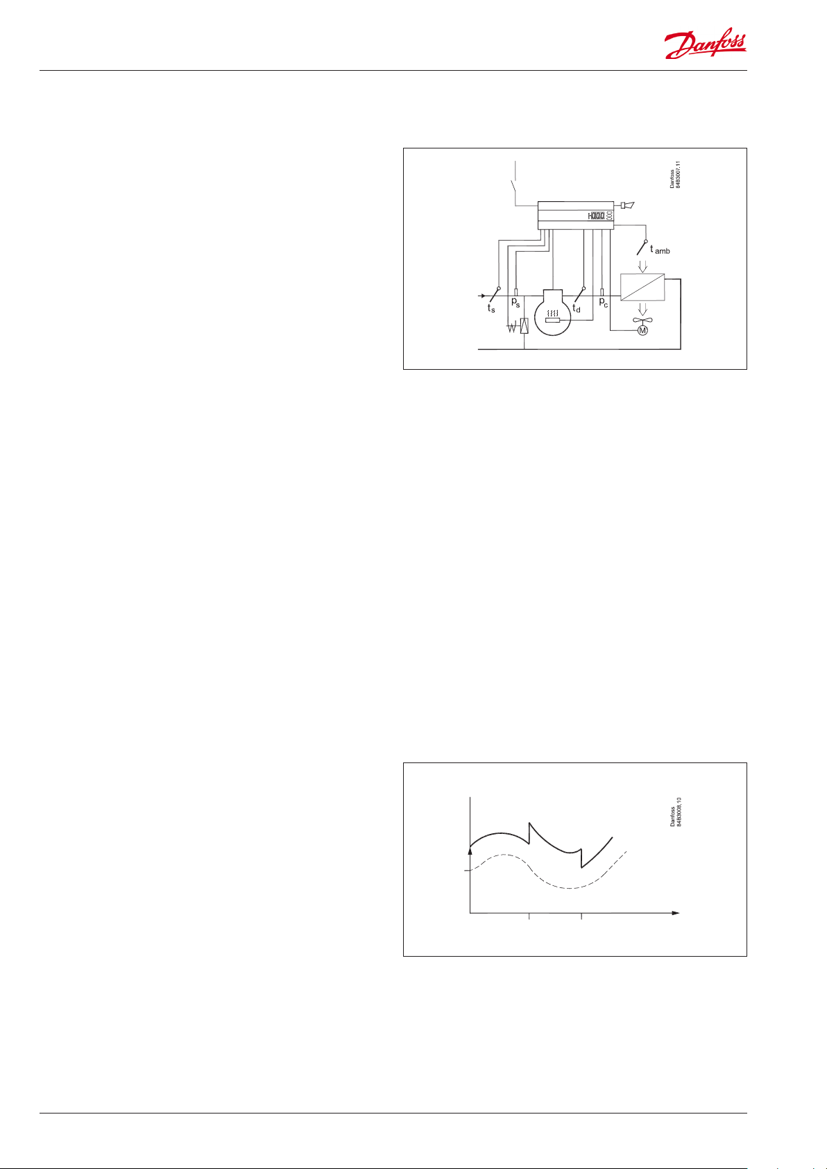
Regulation reference for condensing temperature
The controller controls the condensing temperature in relation
to the ambient temperature. A set point is entered for how much
higher the reference must be. The reference can be raised at night.
Day/Night
The controller has an internal clock function which changes
between daytime and night operation.
During night operation, the reference is raised by the 'Night offset'
value.
This day/night signal can also be activated in two other ways:
• Via an on/off input signal - DI2
• Via data communication.
Set Point
Reference
Tamb
Day
Night offset
Night
Day
2 User Guide RS8KF102 © Danfoss 2019-03 AK-CC 421
Page 3
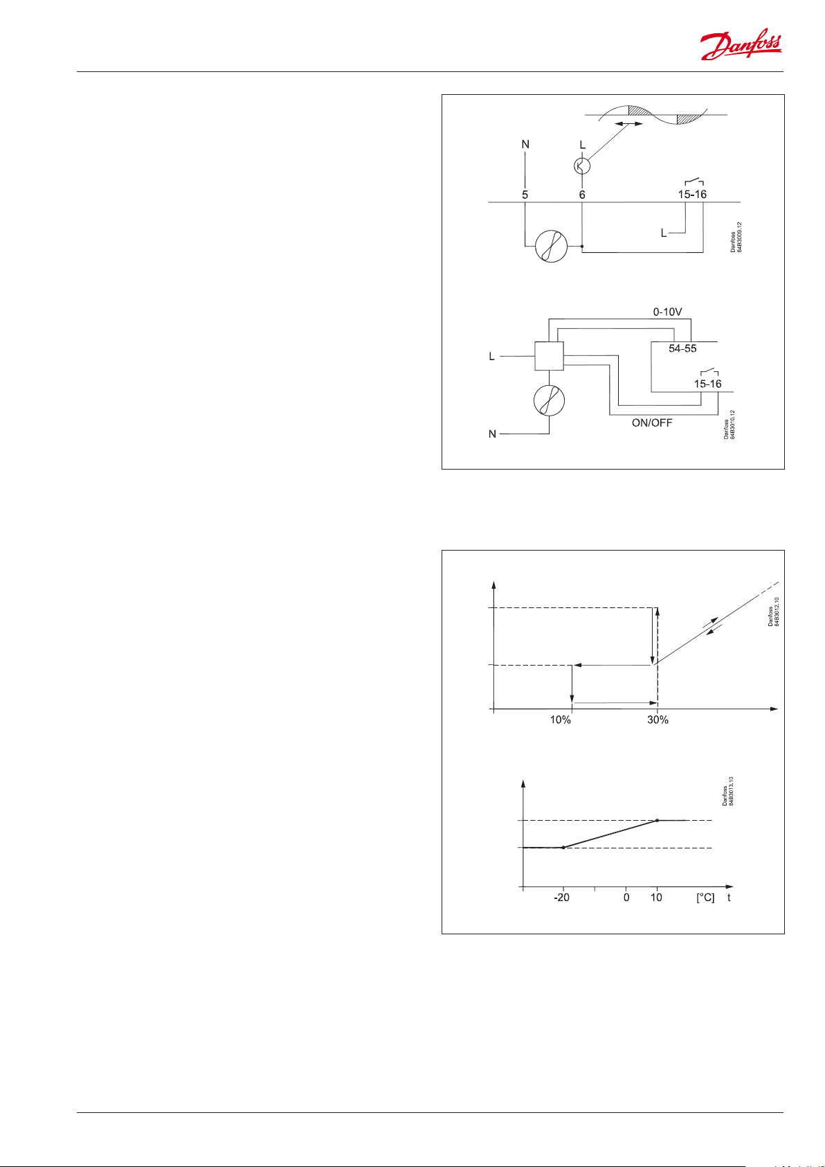
Fan operation
The controller will control the fan so that the condensing
temperature is maintained at the desired value above the outdoor
temperature.
The user may select from different ways to control the fan:
• Internal speed regulation
Here the fan is speed-controlled via terminal 5-6.
At a need of 95% and above, the relay on terminal 15-16 are
activated, while 5-6 are deactivated.
• External speed regulation
For larger fan motors with insufficient internal outlet, an external
speed regulation can be connected to terminal 54-55. A 0-10 V
signal indicating the desired speed is then sent from this point.
The relay on terminal 15-16 will be active when the fan is in
operation.
In menu 'F17' the user can define which of the two controls to use.
Fan speed at start
When the fan is re-started after an idle period, it will be started
at a speed that is set in the 'Jog Speed' function. This speed is
maintained for 10 seconds, after which the speed changes to the
regulation need.
Fan speed at low loads
At low loads between 10 and 30%, the speed will remain at that
which is set in the 'FanMinSpeed' function.
Fan speed at low ambient temperatures
To avoid frequent start/stops in low ambient temperatures in
which the fan's capacity is high, the internal amplification factor is
lowered. This provides a smoother regulation.
The 'Jog speed' is also lowered in the area from 10°C and down to
-20°C.
At temperatures below -20°C the 'Jog Low' value can be used.
Speed
Jog
Min.
Speed
Jog low
Jog
Required
capacity
AK-CC 421
User Guide RS8KF102 © Danfoss 2019-03 3
Page 4
Compressor control
The compressor is controlled by a signal at the DI1 input.
The compressor will start once the input is connected.
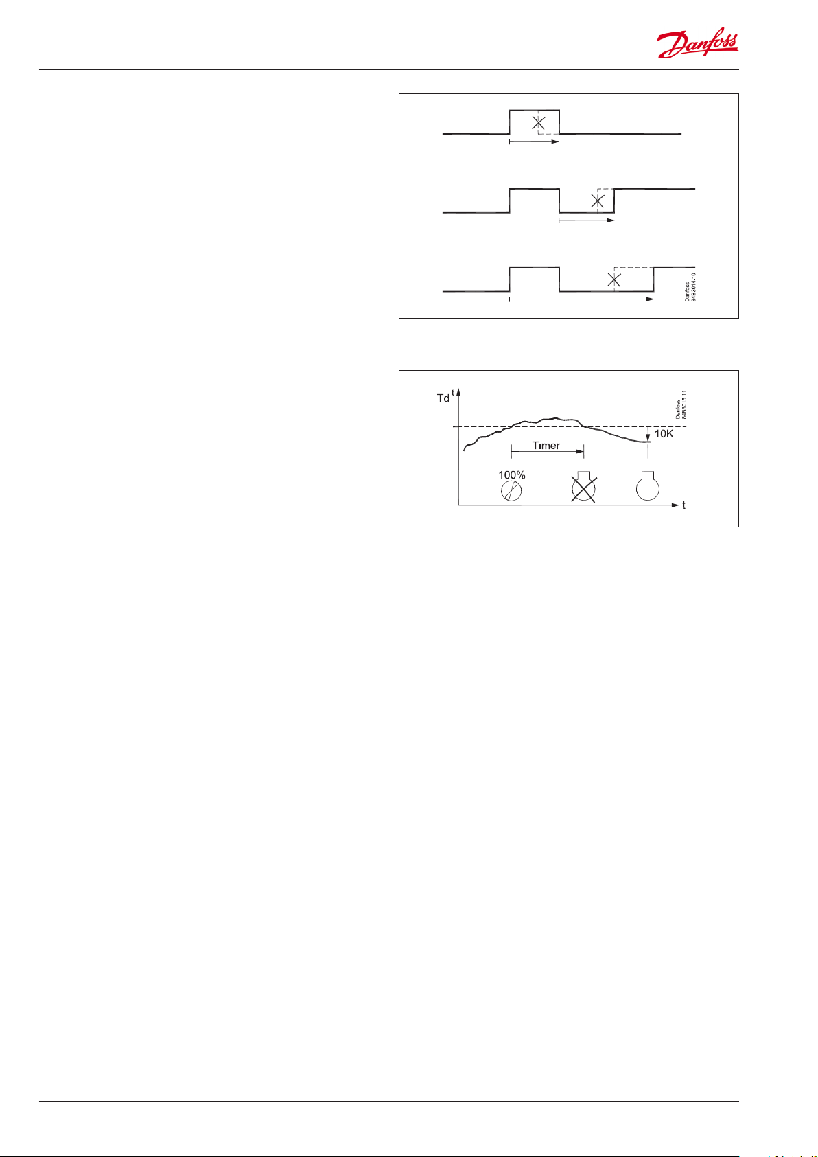
Three restrictions have been implemented to avoid frequent start/
stops:
- One for minimum ON time
- One for minimum OFF time
- One for how much time must elapse between two starts.
These three restrictions have the highest priority during
regulation, and the other functions will wait until they are
complete before regulation can continue. When the compressor is
'locked' by a restriction, this can be seen in a status notification.
If the DI3 input is used as a safety stop for the compressor, an
insufficient input signal will immediately stop the compressor.
The compressor can be speed-controlled with a voltage signal at
the AO2 output.
If the compressor has been running for a long period at low speed,
the speed is increased for a short moment for the purpose of oilreturn.
Maximum discharge gas temperature
The temperature is recorded by sensor Td.
If variable speed control is chosen for the compressor, this control
will initially reduce the compressor capacity if the Td temperature
approaches the set maximum value.
If a higher temperature is detected than the set max. temperature,
the fan's speed will be set to 100%. If this does not cause the
temperature to drop, and if the temperature remains high
after the set delay time, the compressor will be stopped. The
compressor will only be re-started once the temperature is
10 K lower than the set value. The above mentioned re-start
restrictions must also be complete before the compressor can
start once again.
If the delay time is set to '0', the function will not stop the
compressor. The Td sensor can be deactivated (o63).
Liquid injection into economizer port
The controller can activate the liquid injection into economizer
port if the discharge temperature is approaching the maximum
allowable temperature.
Note: Liquid injection function use the Aux Relay.
High pressure monitoring
During regulation, the internal high pressure monitoring function
is able to detect an over the limit condensing pressure so that the
regulation can continue.
However, if the C73 setting is exceeded, the compressor will be
stopped.
If, on the other hand, the signal comes from the interrupted safety
circuit connected to DI3, the compressor will immediately be
stopped and the fan will be set to 100%.
When the signal is once again 'OK' at the DI3 input, the regulation
will resume.
Low pressure monitoring
During regulation, the internal low pressure monitoring function
will cut out the compressor upon detecting a suction pressure that
falls below the lower limit, but only once the minimum ON time
is exceeded. An alarm will be issued. This function will be time
delayed, if the compressor starts at low ambient temperature.
Pump down limit
The compressor will be stopped if a suction pressure that falls
below the set value is registered, but only once the minimum ON
time is exceeded.
4 User Guide RS8KF102 © Danfoss 2019-03 AK-CC 421
Page 5
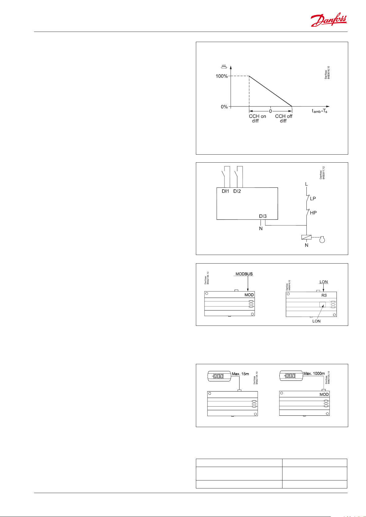
Heating element in the crankcase
The controller has a thermostat function which can control the
heating element for the crankcase. Oil can thus be kept separate
from the refrigerant. The function is active when the compressor
has stopped.
The function is based on the ambient temperature and suction
gas temperature. When the two temperatures are equal ± a
temperature difference, power will be supplied to the heating
element.
The 'CCH off diff' setting indicates when power will no longer be
supplied to the heating element.
The 'CCH on diff' indicates when 100% power will be sent to the
heating element.
Between the two settings the controller calculates the wattage
and connects to the heating element in a pulse/pause cycle which
corresponds to the desired wattage.
The Taux sensor can be used to record the temperature in the
crankcase if desired.
When the Taux sensor records a temperature lower than Ts+10 K,
the heating element will be set to 100%, but only if the ambient
temperature is below 0°C.
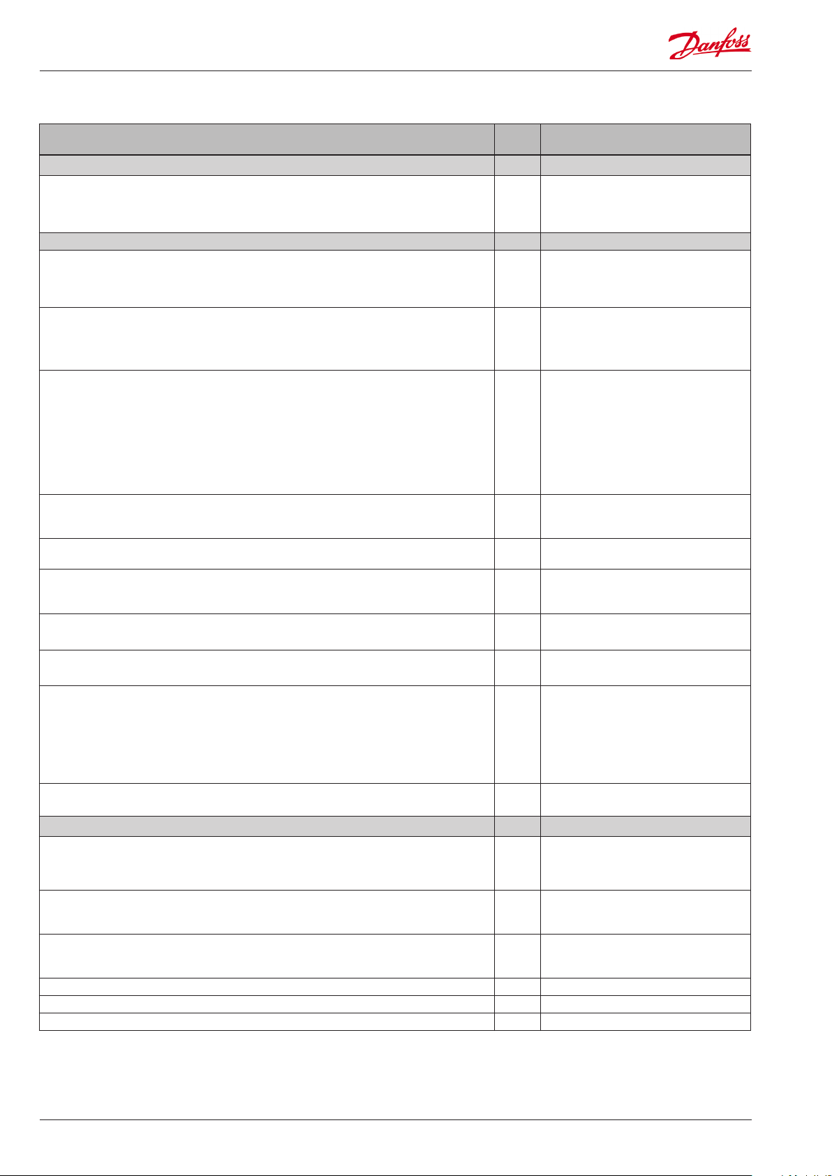
Digital inputs
There are two digital inputs DI1 and DI2 with contact function and
one digital input DI3 with high voltage signal.
They can be used for the following functions:
DI1: Starts and stops compressor
DI2: Here the user can select from various functions
Status notification from an external safety function
External main switch
Night setback signal
Separate alarm function
Monitoring of input signal
DI3: Safety signal from low/high-pressure switch
Data communication
The controller is delivered with built-in MODBUS data
communication.
If a different form of data communication is requested, a LON RS485 module can be inserted in the controller.
The connection will then be made on terminal RS 485.
Important
All connections to the data communication must comply with the
requirements for data communication cables.
See literature: RC8AC.
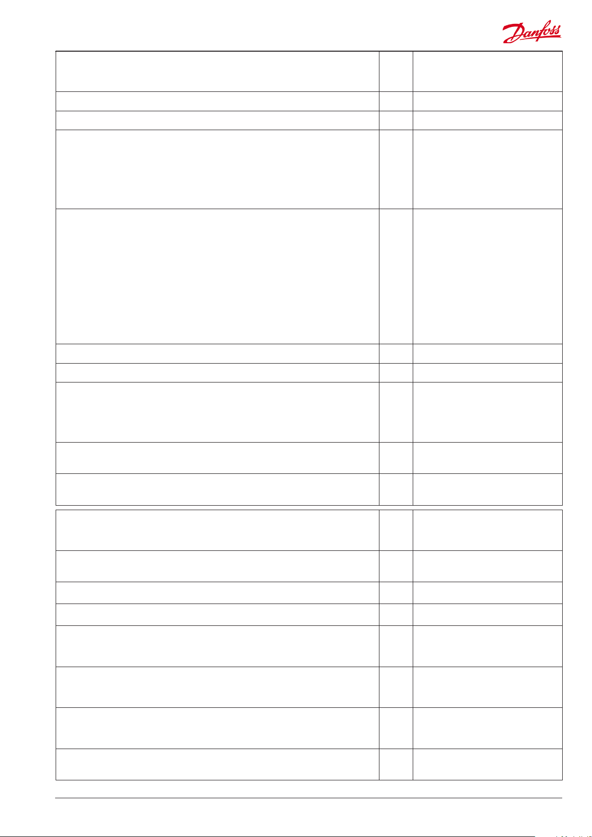
Display
The controller has one plug for a display. Here display type EKA
163B or EKA 164B (max. length 15m) can be connected.
EKA 163B is a display for readings.
EKA 164B is both for readings and operation.
The connection between display and controller must be with a
cable which has a plug at both ends.
A setting can be made to determine whether the Tc or Ts is to be
read out. When the value is read out, the second read-out can be
displayed by briefly pressing the lower button.
When a display is to be connected to the built-in MODBUS, the
display can advantageously be changed to one of the same type,
but with Index A (version with screw terminals).
The controllers address must be set higher than 0 in order for the
display to be able to communicate with the controller.
If connection of two displays is required, one must be connected
to the plug (max. 15 m) and the other must then be connected to
the fixed data communication.
Address o03 > 0
Override
The controller contains a functions which can be used together
with the override function in the master gateway/system manager.
AK-CC 421
User Guide RS8KF102 © Danfoss 2019-03 5
Function via data communication Day/Night schedule
Function in gateway/system manager Day/Night control / Time
schedule
Used parameters in AK-CC 421 --- Night setback
Page 6
Survey of functions
Function Para-
meter
Normal display
The display shows the temperature value for the suction pressure Ts or from the condensing pressure Tc. Enter which of the two are to be displayed in o17.
During operation, when one of the two is shown in the display, the other value can be
seen by pressing and holding in the lower button.
Thermostat Thermostat control
Set point
The controller's reference Tc is the outside temperature + set point + any applicable
offset.
Enter the set point by pressing the middle button. A offset can be entered in r13.
Unit
Set here if the display is to show SI-units or US-units
0: SI (°C and bar)
1: US (°F and Psig).
Start / stop of refrigeration
With this setting refrigeration can be started, stopped or a manual override of the
outputs can be allowed. (For manual control the value is set at -1. Then the relay outlets can be force-controlled by the respective reading parameters (u58, u59 etc.). Here
the read value can be overwritten.)
Start / stop of refrigeration can also be accomplished with the external switch function connected to a DI input.
If the external switch function is deselected, the input must be shorted.
Stopped refrigeration will give a ”Standby alarm”.
Night setback value
The controller reference is raised by this value when the controller switches to night
operation.
Reference Ts
Here the reference is entered for the suction pressure Ts in degrees.
Reference Tc
Here the current controller reference for condensing pressure Tc can be read out in
degrees.
Minimum condensing temperature (lowest permitted regulation reference)
Here the lowest permitted reference is entered for the condensing temperature Tc.
Maximum condensing temperature (highest permitted regulation reference)
Here the highest permitted reference is entered for the condensing temperature Tc.
Maximum discharge gas temperature
Here the highest permitted discharge gas temperature is entered. The temperature
is measured by sensor Td. If the temperature is exceeded, the fan will be started at
100%. A timer is also started which can be set in c72. If the timer setting runs out,
the compressor will be stopped and an alarm will be issued. The compressor will be
reconnected 10 K below the cut-out limit, but only after the compressor's off timer
has expired.
Alarm Alarm settings
The controller can give alarm in different situations. When there is an alarm all the
light-emitting diodes (LED) will flash on the controller front panel, and the alarm relay
will cut in.
Delay of a DI2 alarm
A cut-out/cut-in input will result in alarm when the time delay has been passed. The
function is defined in o37
High condensing temperature
The limit value (difference over normal reference) to which the condensing temperature has increased, and at which an alarm must be issued. Can be set in K.
Delay time for alarm A70. Set in minutes. A71 Air flow del
Parameter by operation via data
communication
Ts / Tc
Reference
r05 Unit
°C=0. / °F=1
(Only °C on AKM, whatever the setting)
r12 Main Switch
1: Start
0: Stop
-1: Manual control of outputs allowed
r13 Night offset
r23 Ts Ref
r29 Tc Ref
r82 MinCondTemp
r83 MaxCondTemp
r84 MaxDischTemp
Night setbck
(start of night signal. 0=Day, 1=Night)
With data communication the importance of the individual alarms can be
defined. Setting is carried out in the
“Alarm destinations” menu via AKM.
A28 AI.Delay DI2
A70 Air flowDiff
Reset alarm
Ctrl. Error
6 User Guide RS8KF102 © Danfoss 2019-03 AK-CC 421
Page 7

Compressor Compressor control
The start/stop of the controller can be defined in several ways.
Internal only: Here, only the internal main switch in r12 is used.
External: Here, input DI1 is used as a thermostat switch. With this setting, input DI2
can be defined as an 'external safety' mechanism that can stop the compressor.
Running times
To prevent irregular operation, values can be set for the time the compressor is to run
once it has been started. And for how long it at least has to be stopped.
Min. ON-time (in seconds)
Min. OFF-time (in seconds)
c01 Min. On time
c02 Min. Off time
Minimum time between cut-in of relay (in minutes) c07 Restart time
Pump down Limit
c33 PumpDownLim
Pressure value at which the compressor stops
Compressor min. speed
c46 CmpMinSpeed
Here the minimum allowable speed for the compressor is set.
Compressor start speed
c47 CmpStrSpeed
The compressor will not start before the required speed can be achieved
Compressor max. speed
c48 CmpMaxSpeed
Upper limit for compressor speed
Compressor max. speed during night operation
c69 CmpMax % Ngt
Upper limit for compressor speed during night operation. During night operation, the
c48 value is reduced to the percentage value set here
Definition of compressor control
c71 Comp mode
0: No external switch for start/stop
1: Input DI1 used to start and stop the compressor
2: The compressor will be speed-controlled with a 0-10 V signal on AO2
Delay time for high discharge gas temperature (in minutes)
c72 Disch. Del
When sensor Td records a temperature higher than the limit value entered in r84, the
timer will start. When the delay time expires, the compressor will be stopped if the
temperature is still too high. An alarm will also be issued.
Max. pressure (Max. condensing pressure)
c73 PcMax
The maximum permitted condensing pressure is set here. If the pressure increases,
the compressor will be stopped.
Difference for max. pressure (Condensing pressure)
c74 Pc Diff
Difference for re-start of compressor if it is cut out due to PcMax.
(All timers must expire before re-start is permitted)
Minimum suction pressure
c75 PsLP
Enter the lowest permitted suction pressure here. The compressor is stopped if the
pressure drops below the minimum value.
Suction pressure difference
c76 PsDiff
Difference for re-start of compressor if it is cut out due to PsLP.
(All timers must expire before re-start is permitted)
Amplification factor Kp for compressor regulation
c82 Cmp Kp
If the Kp value is lowered, the regulation will be slower
Integration time Tn for compressor regulation
c83 Comp Tn sec
If the Tn value is increased, regulation will run more smoothly
Liquid Injection Offset
c88 LI Offset
The liquid injection relay is activated when the temperature is over “r84” minus “c88”
(but only if the compressor is running).
Liquid Injection hysterese
c89 LI Hyst
The liquid injection relay is then deactivated when the temperature has dropped to
“r84” minus “c88” minus “c89”.
Compressor stop delay after Liquid injection
c90 LI Delay
Compressor ON-time after relay "Aux relay" is went OFF
Desired compressor speed in connection with pressure transmitter faults.
c93 CmpEmrgSpeed
Speed during emergency operation.
Min On time during Low Ambient Temperature and Low Pressure
Measured Tc for which the Comp min speed is raised to StartSpeed
c94 c94 LpMinOnTime
c95 c95 TcSpeedLim
The LED on the controller’s front will show whether refrigeration is in progress.
Fan Fan control
Amplification factor Kp
n04 Kp factor
If the KP value is lowered, the fan speed will change.
AK-CC 421
User Guide RS8KF102 © Danfoss 2019-03 7
Page 8

Integration Time Tn
If the Tn value is increased, the fan speed will change.
Amplification factor Kp max
The regulation uses this Kp, when the measured value is far from reference
Fan speed
The actual fan speed is read out here as a % of nominal speed.
Change in fan speed
A permitted change in fan speed can be entered for when the fan speed is to be lowered. The setting can be entered as a percentage value per second.
Jog speed
Set the fan's start-up speed here. After ten seconds the function jog function will stop
and the fan speed will then be controlled by the normal regulation.
Jog speed at low temperatures
Enter the desired jog speed for outside temperatures of -20°C and lower here.
(For outside temperatures between +10 and -20, the controller will calculate and
utilise a speed between the two jog settings.)
Fan control definition
0: Off
1: The fan is connected to terminal 5-6 and is speed-controlled by an internal phase
cut. The relay on terminal 15-16 connects at speed requirements of 95% or higher.
2: The fan is connected to an external speed control device. The speed control signal
is connected to terminals 28-29. The relay on terminal 15-16 will connect when
regulation is required. (During external control, the settings F14, F15 and F16 will
remain in force)
Minimum fan speed
Set the lowest permitted fan speed here. The fan will be stopped if the user enters a
lower speed.
Maximum fan speed
The fan's top speed can be limited here. The value can be entered by setting the
nominal speed of 100% to the desired percentage.
Manual fan speed control
An override of the fan speed control can be performed here. This function is only
relevant when the main switch is in service mode.
The LED on the controller’s front will show whether Fan is in progress supplied either
through fan speed control output or fan relay.
n05 Tn sec
n95 Cmp kp Max
F07 Fan Speed %
F14 DownSlope
F15 Jog Speed
F16 LowTempJog
F17 FanCtrlMode
F18 MinFanSpeed
F19 MaxFanSpeed
F20 Manual Fan %
Real time clock
When using data communication the clock is automatically adjusted by the system
unit. If the controller is without data communication, the clock will have a power
reserve of four hours.
Switch to day operation
Enter the time at which the control reference becomes the entered set point.
Change to night operation
Enter the time at which the control reference is raised with r13.
Clock: Hour setting
Clock: Minute setting
Clock: Date setting
Clock: Month setting
Clock: Year setting
Miscellaneous Miscellaneous
If the controller is built into a network with data communication, it must have an ad-
dress, and the system unit of the data communication must then know this address.
The address is set between 0 and 240, depending on the system unit and the selected
data communication.
The function is not used when the data communication is MODBUS. It is retrieved
here via the system's scan function.
Access code 1 (Access to all settings)
If the settings in the controller are to be protected with an access code you can set a
numerical value between 0 and 100. If not, you can cancel the function with setting 0.
(99 will always give you access).
Controller software version o08 SW ver
(Times cannot be set via data communication. Settings are only relevant
when there is no data communication).
t17 Day start
t18 Night start
t07
t08
t45
t46
t47
o03
o04
o05 Acc. code
8 User Guide RS8KF102 © Danfoss 2019-03 AK-CC 421
Page 9
Select signal for the display
Here you define the signal to be shown by the display.
1: Suction pressure in degrees, Ts.
2: Condensing pressure in degrees, Tc.
Pressure transmitter settings for Ps
Working range for pressure transmitter - min. value
Pressure transmitter settings for Ps
Working range for pressure transmitter - max. value
Refrigerant setting (only if "r12" = 0)
Before refrigeration is started, the refrigerant must be defined. You may choose between the following refrigerants
2=R22. 3=R134a. 13=User defined. 17=R507. 19=R404A. 20=R407C. 21=R407A.
37=R407F.
Warning: Wrong selection of refrigerant may cause damage to the compressor.
Other refrigerants: Here Setting 13 is selected and then three factors -Ref.Fac a1, a2
and a3 - via AKM must be set.
Digital input signal - D2
The controller has a digital input 2 which can be used for one of the following functions:
0: The input is not used.
1: Status display from an external safety function (short-circuited =ok for compressor
operation)
2: Main switch. Regulation is carried out when the input is short-circuited, and regula-
tion is stopped when the input is put in pos. OFF.
3: Night operation. When the input is short-circuited, there will be regulation for night
operation.
4: Separate alarm function. Alarm will be given when the input is short-circuited.
5: Separate alarm function. Alarm will be given when the input is opened.
6: Input status, on or off. (DI2 status can be tracked via data communication)
7: Alarm from the compressor's external speed control.
Pressure transmitter settings for PC
Working range for pressure transmitter - min. value
Pressure transmitter settings for PC
Working range for pressure transmitter - max. value
Select the type of condensing unit.
Factory set.
After the first setting, the value is 'locked' and can only be changed once the controller has been reset to its factory setting.
When entering the refrigerant setting, the controller will ensure that the 'Unit type'
and refrigerant are compatible.
S3 Configuration
0 = S3 input not used
1 = S3 input used for measuring of discharge temperature
Save as factory setting
With this setting you save the controller’s actual settings as a new basic setting (the
earlier factory settings are overwritten).
Define the use of the Taux sensor (S5)
0: Not used
1: Used to measure oil temperature
2: Other use. Measuring of optional temperature.
Period time for heating element in crankcase
Within this period the controller will itself calculate an OFF and ON period.
The time is entered in seconds.
Difference for the heating elements 100% ON point
The difference applies to a number of degrees below the 'Tamb minus Ts = 0 K' value.
Difference for the heating elements full OFF point
The difference applies to a number of degrees above the 'Tamb minus Ts = 0 K' value
Operating time for condensing unit
The condensing unit's operating time can be read out here. The read-out value must
be multiplied by 1,000 in order to obtain the correct value.
(The displayed value can be adjusted if required)
Operating time for the compressor
The compressors operating time can be read out here. The read-out value must be
multiplied by 1,000 in order to obtain the correct value.
(The displayed value can be adjusted if required)
Operating time for heating element in crankcase
The heating element's operating time can be read out here. The read-out value must
be multiplied by 1,000 in order to obtain the correct value.
(The displayed value can be adjusted if required)
Number of HP alarms
The number of HP alarms can be read out here.
(The displayed value can be adjusted if required)
o17 Display mode
o20 MinTransPs
o21 MaxTransPs
o30 Refrigerant
o37 DI2 config.
o47 MinTransPc
o48 MaxTransPc
o61 Unit type
o63 S3 config
o67 -
o69 Taux Config
P45 PWM Period
P46 CCH_OnDiff
P47 CCH_OffDiff
P48 Unit Runtime
P49 Comp Runtime
P50 CCH Runtime
P51 HP Alarm Cnt
AK-CC 421
User Guide RS8KF102 © Danfoss 2019-03 9
Page 10

Number of LP alarms
The number of LP alarms can be read out here.
(The displayed value can be adjusted if required)
Number of discharge alarms
The number of Td alarms can be read out here.
(The displayed value can be adjusted if required)
Oil return management Speed limit
If the compressor speed exceeds this limit, a time counter will be increased. It will be
decreased if the compressor speed falls down below this limit.
Oil return management time
Limit value of the above described time counter. If the counter exceeds this limit, the
compressor speed will be raised to the Boost speed
Oil return management Boost speed
This compressor speed ensures that the oil returns to the compressor
Oil return management Boost time.
The time the compressor must operate at Boost speed.
Service Service
Read pressure Pc u01 Pc bar
Read temperature Taux u03 T_aux
Status on DI1 input. On/1=closed u10 DI1 status
Status on night operation (on or off) on =night operation u13 NightCond
Read Superheat u21 Superheat SH
Read temperature at S6 sensor u36 S6 temp
Read the compressor capacity in % u52 CompCap %
Status on DI2 input. On/1=closed u37 DI2 status
Status on relay for compressor u58 Comp Relay
Status on relay for fan u59 Fan relay
Status on relay for alarm u62 Alarm relay
Status on relay "Aux" u63 Aux Relay
Status on relay for heating element in crankcase
Status on input DI3 (on/1 = 230 V)
Read condensing pressure in temperature
Read pressure Ps
Read suction pressure in temperature
Read ambient temperature Tamb
Read discharge temperature Td
Read suction gas temperature at Ts
Voltage on the analogue output AO1
Voltage on the analogue output AO2
P52 LP Alarm Cnt
P53 DisAlarm Cnt
P77 ORM SpeedLim
P78 ORM Time
P79 ORM BoostSpd
P80 ORM BoostTim
u71 CCH Relay
u87 DI3 status
U22 Tc
U23 Ps
U24 Ts
U25 T_ambient
U26 T_Discharge
U27 T_Suction
U44 AO_1 Volt
U56 AO_2 Volt
10 User Guide RS8KF102 © Danfoss 2019-03 AK-CC 421
Page 11

Operating status (Measurement)
The controller goes through some regulating situations where it is just waiting for
Ctrl. state:
the next point of the regulation. To make these “why is nothing happening” situations
visible, you can see an operating status on the display. Push briefly (1s) the upper
button. If there is a status code, it will be shown on the display. The individual status
codes have the following meanings:
Normal regulation S0 0
When the compressor is operating it must run for at least x minutes. S2 2
When the compressor is stopped, it must remain stopped for at least x minutes. S3 3
Refrigeration stopped by main switch. Either with r12 or a DI-input S10 10
Manual control of outputs S25 25
No refrigerant selected S26 26
Safety cut-out Max. condensing pressure exceeded. All compressors stopped. S34 34
Other displays:
Password required. Set password PS
Regulation is stopped via main switch OFF
No refrigerant selected ref
No type has been selected for the condensing unit. typ
AK-CC 421
User Guide RS8KF102 © Danfoss 2019-03 11
Page 12

Fault message
In an error situation the LED’s on the front will flash and the alarm relay will be activated. If you push the top button in this situation you can see the
alarm report in the display.
There are two kinds of error reports - it can either be an alarm occurring during the daily operation, or there may be a defect in the installation.
A-alarms will not become visible until the set time delay has expired.
E-alarms, on the other hand, will become visible the moment the error occurs.
(An A alarm will not be visible as long as there is an active E alarm).
Here are the messages that may appear:
Code / Alarm text via data
communication
A2/--- LP alarm Low suction pressure See instructions for the condensing unit
A11/--- No Rfg. sel. No refrigerant selected Set o30
A16 /--- DI2 alarm DI2 alarm Check the function that sends a signal at the DI2 input
A17 / ---HP Alarm C73 / DI3 Alarm (High / low pressure alarm) See instructions for the condensing unit
A45 /--- Standby mode Standby position (stopped refrigeration via r12 or DI1-input) r12 and/or DI1 input will start the regulation
A80 / --- Cond. blocked Air flow has decreased. Clean the condensing unit
A96 / --- Max Disc. Temp Discharge gas temperature is exceeded See instructions for the condensing unit
A97 / --- Safety alarm Safety function on DI2 is activated Check the function that sends a signal at the DI2 input
A98 / --- Drive alarm Alarm from speed regulation Check speed regulation
E1 /--- Ctrl. Error Faults in the controller
E20 /--- Pc Sensor Err Error on pressure transmitter Pc
E30 /--- Taux Sensor Err Error on Aux sensor, S5
E31/---Tamb Sensor Err Error on air sensor, S2
E32 / ---Tdis Sensor Err Error on discharge sensor, S3
E33 / ---Tsuc Sensor Err Error on suction gas sensor, S4
E39/--- Ps Sensor Err Error on pressure transmitter Ps
Data communication
The importance of individual alarms can be defined with a setting. The setting must be carried out in the group "Alarm destinations"
Settings from
System manager
High 1 X X X X
Middle 2 X X X
Low 3 X X X
Log only X
Disabled
Description Action
and the direction of rotation of the compressor
Check sensor and connection
Settings from
AKM (AKM destination)
Log Alarm relay Send via
Non High Low-High
Network
12 User Guide RS8KF102 © Danfoss 2019-03 AK-CC 421
Page 13

Operation
Display
The values will be shown with three digits, and with a setting you
can determine whether the temperature is to be shown in °C or in
°F.
Light-emitting diodes (LED) on front panel
The LED’s on the front panel will light up when the relevant relay
is activated.
= Refrigeration
= heating element in crankcase is on
= Fan running
The light-emitting diodes will flash when there is an alarm.
In this situation you can download the error code to the display
and cancel/sign for the alarm by giving the upper button a brief
push.
The buttons
When you want to change a setting, the upper and the lower button will give you a higher or lower value depending on the button
you are pushing. But before you change the value, you must have
access to the menu. You obtain this by pushing the upper button
for a couple of seconds - you will then enter the column with parameter codes. Find the parameter code you want to change and
push the middle buttons until value for the parameter is shown.
When you have changed the value, save the new value by once
more pushing the middle button.
(If not operated for 20 (5) seconds, the display will change back to
the Ts/Tc temperature display).
Cutout alarm relay / receipt alarm/see alarm code
• A short press of the upper button
If there are several alarm codes they are found in a rolling stack.
Push the uppermost or lowermost button to scan the rolling
stack.
Set point
1. Push the middle button until the temperature value is shown
2. Push the upper or the lower button and select the new value
3. Push the middle button again to conclude the setting.
Reading the temperature at Ts (if Tc is the primary display) or Tc (if Ts
is the primary display)
• A short press of the lower button
Get a good start
With the following procedure you can start regulation very quickly:
1 Open parameter r12 and stop the regulation (in a new and not
previously set unit, r12 will already be set to 0 which means
stopped regulation.
2 Select refrigerant via parameter o30
3 Open parameter r12 and start the regulation. Start/stop at input
DI1 or DI2 must also be activated.
4 Go through the survey of factory settings. Make any necessary
changes in the respective parameters.
5 For network.
- Set the address in o03
- Activate scan function in the system manager.
Examples
Note
When delivering the condensing unit, the controller will be set to
Set menu
1. Push the upper button until a parameter r05 is shown
2. Push the upper or the lower button and find that parameter you
the condensing unit type (setting o61). This setting will be compared with your refrigerant setting. If you select a "non-permitted
refrigerant", the display will show "ref" and await a new setting.
want to change
3. Push the middle button until the parameter value is shown
4. Push the upper or the lower button and select the new value
(In the event of a controller change, 061 must be set as indicated
in the instructions from Danfoss)
5. Push the middle button again to freeze the value.
Menu survey
Parameter
Function Code
Normal operation
Set point (regulation reference follows the number of degrees above the outside temperature
Tamb)
Regulation
Select SI or US display. 0=SI (bar and °C). 1=US (Psig and °F) r05 0/°C 1/F 0/°C
Internal Main Switch. Manual and service = - 1, Stop regulation = 0, Start regulation =1 r12 -1 1 0
Offset during night operation. During night operation the reference is raised by this value r13 0 K 10 K 2 K
Set point for suction pressure Ts r23 -25 °C 10°C -7°C
Readout of reference for Tc r29 - - - -
Min. condensing temperature (lowest permitted Tc reference) r82 0°C 40°C 10°C
Min.-value Max.-value
- - - 2.0 K 20.0 K 8.0 K
Factory
setting
SW = 3.1x
Actual
setting
AK-CC 421
User Guide RS8KF102 © Danfoss 2019-03 13
Page 14

continued Code Min. Max. Fac. Actual
Max. condensing temperature (highest permitted Tc reference) r83 0°C 50°C 40°C
Max. discharge gas temperature Td r84 50°C 160°C 135°C
Alarms
Alarm time delay on signal on the DI2 input A28 0 min. 240 min. 30 min.
Alarm for insufficient cooling in condenser. Set temperature difference. A70 3.0 K 20.0 K 10.0 K
Delay time for A70 alarm A71 5 min. 240 min. 30 min.
Compressor
Min. ON-time
Min. OFF-time
Min. time between compressor starts
Pump down limit at which the compressor is stopped (setting 0.0 = no function)
Min. compressor speed
Start speed for compressor
Max. compressor speed
Max. compressor speed during night operation (%-value of c48)
Definition of compressor control: 0=no external start/stop; 1=switch on DI1 must start/stop
c01 5 s 240 s 5 s
c02 3 s 240 s 30 s
c07 0 min. 30 min. 5 min.
C33 0,0 bar 15,0 bar 0,0 bar
c46 25 Hz 70 Hz 30 Hz
c47 30 Hz 70 Hz 50 Hz
c48 50 Hz 100 Hz 100 Hz
c69 50% 100% 70%
c71 0 2 1
; 2=inverter compressor speed control
Time delay for high Td. The compressor will stop when time expires.
Max. pressure. Compressor stops if a higher pressure is recorded
Difference for max. pressure (c73)
Min. suction pressure Ps. Compressor stops if a lower pressure is recorded
Difference for min. suction pressure and pump down
Amplification factor Kp for compressors PI-regulation
Integration time Tn for compressors PI-regulation
Liquid Injection Offset
Liquid Injection hysterese
Compressor stop delay after Liquid injection
Desired compressor speed if the signal from the pressure transmitter Ps fails
Min On time during Low Ambient LP
Measured Tc for which the Comp min speed is raised to StartSpeed
c72 0 min. 20 min. 3 min.
c73 7.0 bar 50.0 bar 23.0 bar
c74 1.0 bar 10.0 bar 3.0 bar
c75 -0.3 bar 10.0 bar 3.0 bar
c76 0.1 bar 5.0 bar 0.7 bar
c82 3,0 30,0 20,0
c83 30 s 360 s 60 s
c88 0.1 K 20.0 K 5.0 K
c89 10.0 K 30.0 K 15.0 K
c90 0 s 10 s 3 s
c93 25 Hz 70 Hz 60 Hz
c94 0 0 120
c95 40,0 10,0 70,0
Control parameters
Amplification factor Kp for PI-regulation n04 1.0 20.0 7.0
Integration time Tn for PI-regulation n05 20 120 40
Kp max for PI regulation when the measurement is far from reference n95 5,0 50,0 20,0
Fan
Readout of fan speed in % F07 - - -
Permitted change in fan speed (to a lower value) % per second. F14 1,0% 5,0% 1,0%
Jog speed (speed as a % when the fan is started) F15 10% 100% 40%
Jog speed at low temperature F16 0% 40% 10%
Definition of fan control: 0=Off; 1=Internal control. 2=External speed control F17 0 2 1
Minimum fan speed. Decreased need will stop the fan. F18 0% 40% 10%
Maximum fan speed F19 40% 100% 100%
Manual control of the fan's speed. (Only when r12 is set to -1) F20 0% 100% 0%
Real time clock
Time at which they switch to day operation t17 0 hrs 23 hrs 0
Time at which they switch to night operation t18 0 hrs 23 hrs 0
Clock - Setting of hours
Clock - Setting of minute
Clock - Setting of date
Clock - Setting of month
Clock - Setting of year
Miscellaneous
t07 0 hrs 23 hrs 0
t08 0 min. 59 min. 0
t45 1 day 31 day 1
t46 1 mon. 12 mon. 1
t47 0 year 99 year 0
Network address o03 0 240 0
On/Off switch (Service Pin message)
o04 0/Off 1/On 0/Off
IMPORTANT! o61 must be set prior to o04
(used at LON 485 only)
Access code (access to all settings) o05 0 100 0
Readout of controllers software version o08
14 User Guide RS8KF102 © Danfoss 2019-03 AK-CC 421
Page 15

continued Code Min. Max. Fac. Actual
Select signal for display view. 1=Suction pressure in degrees, Ts. 2=Condensing pressure in
o17 1 2
1
degrees, Ts
Pressure transmitter working range Ps - min. value o20 -1 bar 5 bar -1
Pressure transmitter working range Ps- max. value o21 6 bar 200 bar 12
Refrigerant setting:
* o30 0 37 0
2=R22. 3=R134a. 13=User defined. 17=R507. 19=R404A. 20=R407C. 21=R407A. 37=R407F
Input signal on DI2. Function:
o37 0 6 0
(0=not used, 1=External safety function. Regulate when closed, 2=external main switch,
3=Night operation when closed, 4=alarm function when closed, 5=alarm function when
open. 6=on/off Status for monitoring.
Pressure transmitter working range Pc– min. value o47 -1 bar 5 bar 0 bar
Pressure transmitter working range Pc – max. value o48 6 bar 200 bar 32 bar
Setting of condensing unit type (is factory set when the controller is mounted and cannot be
* o61 0 45 0
subsequently changed)
The sensor input S3 is to be used to measure the discharge gas temperature (1=yes)
Replace the controllers factory settings with the present settings
Defines the use of the Taux sensor: 0=not used; 1=measuring of oil temperature; 2=other
o63 0 1 1
o67 Off On Off
o69 0 2 0
optional use
Period time for heating element in crankcase (ON + OFF period) P45 30 s 255 s 240 s
Difference for heating elements 100% ON point P46 -20 K -5 K -10 K
Difference for heating elements 100% OFF point P47 5 K 20 K 10 K
Read-out of operating time for condenser unit. (Value must be multiplied by 1,000). The value
P48 - - 0 h
can be adjusted.
Read-out of compressor operating time. (Value must be multiplied by 1,000). The value can be
P49 - - 0 h
adjusted.
Read-out of operating time of heating element in crankcase. (Value must be multiplied by
P50 - - 0 h
1,000). The value can be adjusted.
Read-out of number of HP alarms. The value can be adjusted. P51 - - 0
Read-out of number of LP alarms. The value can be adjusted. P52 - - 0
Read-out of number of Td alarms. The value can be adjusted. P53 - - 0
Oil return management. Compressor speed for the counter starting point P77 25 Hz 70 Hz 40 Hz
Oil return management. Limit value for counter P78 5 min. 720 min. 20 min.
Oil return management. Boost-speed P79 40 Hz 100 Hz 50 Hz
Oil return management. Boost-time. P80 10 s 600 s 60 s
Service
Readout pressure on Pc u01 bar
Readout temperature Taux u03 °C
Status on DI1 input. 1=on=closed u10
Status on night operation (on or off) 1=on=night operation u13
Readout superheat u21 K
Readout temperature at S6 sensor u36 °C
Status on DI2 input. 1=on=closed u37
Readout the compressor capacity in % u52 %
Status on relay to compressor. 1=on=closed ** u58
Status on relay to fan. 1=on=closed ** u59
Status on relay to alarm. 1=on=closed ** u62
Status on relay "Aux". 1=on=closed ** u63
Status on relay to heating element in crank case. 1=on=closed ** u71
Status on high voltage input DI3. 1=on=230 V u87
Readout condensing pressure in temperature U22
Readout pressure Ps U23
Readout suction pressure in temperature U24
Readout ambient temperature Tamb U25
Readout discharge temperature Td U26
Readout suction gas temperature Ts U27
Readout the voltage on the output AO1 U44
Readout the voltage on the output AO2 U56
*) Can only be set when regulation is stopped (r12=0)
**) Can be controlled manually, but only when r12=-1
Factory setting
If you need to return to the factory-set values, it can be done in this way:
- Cut out the supply voltage to the controller
- Keep upper and lower button depressed at the same time as you reconnect the supply voltage
°C
bar
°C
°C
°C
°C
V
V
AK-CC 421
User Guide RS8KF102 © Danfoss 2019-03 15
Page 16

Connections
DI1
Digital input signal.
Used to start/stop cooling (room thermostat)
Starts when the input is short-circuited.
DI2
Digital input signal.
The defined function is active when the input is short-circuited/
opened. The function is defined in o37.
Pc
Pressure transmitter, ratiometric AKS 32R, 0 to 32 bar
Connect to terminal 28, 29 and 30.
Ps
Pressure transmitter, ratiometric e.g. AKS 32R, -1 to 12 bar
Connected to terminal 31, 32 and 33.
S2
Air sensor, Tamb. Pt 1000 ohm sensor, eg. AKS 11
S3
Discharge gas sensor, Td. Pt 1000 ohm sensor, eg. AKS 21
S4
Suction gas temperature, Ts. Pt 1000 ohm sensor, eg. AKS 11
S5,
Extra temperature measurement, Taux. Pt 1000 ohm sensor, eg. AKS 11
S6,
Extra temperature measurement, S6. Pt 1000 ohm sensor, eg. AKS 11
EKA Display
If there is be external reading/operation of the controller, display type
EKA 163B or EKA 164B can be connected.
RS485 (terminal 51, 52,53)
For data communication, but only if a data communication module is
inserted in the controller. The module can be Lon.
If data communication is used, it is important that the installation of
the data communication cable is performed correctly.
See separate literature No. RC8AC…
AO1, terminal 54, 55
Output signal, 0-10 V. Must be used if the fan is equipped with internal
speed control and 0-10 V d.c. input, e.g. EC-motor.
AO2, terminal 56, 57
Output signal, 0-10 V. Must be used if the compressor is speed
controlled.
MODBUS (terminal 60, 61, 62)
Built in Modbus data communication.
If data communication is used, it is important that the installation of
the data communication cable is performed correctly.
See separate literature No. RC8AC…
(Alternatively the terminals can be connected to an external display
type EKA 163A or 164A, but then they cannot be used for data
communication. Any data communication must then be carried out
by one of the other methods.)
Supply voltage
230 V a.c. (This must be the same phase for all 230 V connections).
FAN
Fan connection. Speed controlled internally.
Alarm
There is a connection between terminal 7 and 8 in alarm situations
and when the controller is without power.
Comp
Compressor. There is a connection between terminal 10 and 11, when
the compressor is running.
CCH
Heating element in the crankcase
There is connection between terminals 12 and 14 when heating takes
place.
Fan
There is connection between terminals 15 and 16 when the fan's
speed is raised to over 95%. (Fan signal changes from terminal 5-6 to
15-16. Connect wire from terminal 16 to the fan.)
Aux
Liquid injection in suction line
There is connection between terminals 17 and 19, when the function
is active.
DI3
Digital input signal from low/high pressure monitoring.
The signal must have a voltage of 0 / 230 V AC.
Electric noise
Cables for sensors, DI inputs and data communication must be kept
separate from other electric cables:
- Use separate cable trays
- Keep a distance between cables of at least 10 cm.
- Long cables at the DI input should be avoided
Installation considerations
Accidental damage, poor installation, or site conditions, can give rise
to malfunctions of the control system, and ultimately lead to a plant
breakdown. Every possible safeguard is incorporated into our products to prevent this. However, a wrong installation, for example, could
still present problems. Electronic controls are no substitute for normal,
good engineering practice.
Danfoss will not be responsible for any goods, or plant components,
damaged as a result of the above defects. It is the installer's responsibility to check the installation thoroughly, and to fit the necessary
safety devices. Special reference is made to the necessity of signals
to the controller when the compressor is stopped and to the need of
liquid receivers before the compressors.
Your local Danfoss agent will be pleased to assist with further advice,
etc.
16 User Guide RS8KF102 © Danfoss 2019-03 AK-CC 421
Page 17

Data
Supply voltage 230 V a.c. +10/-15 %. 5 VA, 50 Hz
Sensor S2, S3,
S4, S5, S6
Accuracy
Measuring of
Pc, Ps
Display LED, 3-digits
External display EKA 163B or 164B (any EKA 163A or 164A)
Digital inputs
DI1, DI2
Digital input DI3 230 V a.c. from safety pressostat. Low/high pressure
Electrical connection cable
Triac output
Relays*
Pt 1000
Measuring range
Controller
Pt 1000 sensor
Pressure transmitter
Signal from contact functions
Requirements to contacts: Gold plating
Cable length must be max. 15 m
Use auxiliary relays when the cable is longer
Max.1.5 mm2 multi-core cable
Fan
Comp, CCH 4 (3) A
-60 to +120°C
(S3 to 150°C)
±1 K below -35°C
± 0.5 K between -35 to +25°C;
±1 K above +25°C
±0.3 K at 0°C
±0.005 K per grad
Ratiometric. eg. AKS 32R
Max. 240 V a.c. , Min. 28 V a.c.
Max. 2.0 A
Leak < 1 mA
CE
(250 V a.c.)
Alarm, Fan, Aux 4 (3) A
Analog output
Environments
Density IP 20
Mounting DIN-rail or wall
Weight 0.4 Kg
Data
communication
Power reserve
for the clock
Approvals
* Comp and CCH are 16 A relays. Alarm and Fan are 8 A relays. Max. load must be observed
2 pcs. 0-10 V d.c.
(For external speed control of fans and compressors)
Min. load = 10 K ohm. (Max. 1 mA)
-25 to +55°C, During operations
-40 to +70°C, During transport
20 - 80% Rh, not condensed
No shock influence / vibrations
Fixed MODBUS
Extension options LON
4 hours
EC Low Voltage Directive and EMC demands re CEmarking complied with
LVD tested acc. EN 60730-1 and EN 60730-2-9, A1, A2
EMC-tested acc. EN 61000-6-2 and EN 61000-6-3
AK-CC 421
User Guide RS8KF102 © Danfoss 2019-03 17
Page 18

Ordering
Type Function Code no.
AK-CC 421
Prepared for data communication
084B8081
Plug for screw terminals not enclosed
Plug Plug with screw terminals 084B8166
EKA 175 Data communication module LON RS485 084B8579
EKA 163B External display with plug for direct connection 084B8574
Condensing unit controller
EKA 164B
External display with operation buttons and plug for direct
connections
084B8575
EKA 163A External display with screw terminals 084B8562
EKA 164A External display with operation buttons and screw terminals 084B8563
Wire with plug Wire for display unit (9 m, with plug)
084B7630
(24 pcs.)
EKA 183A Programming key 084B8582
Danfoss can accept no responsibility for possible errors in catalogues, brochures and other printed material. Danfoss reserves the right to alter its products without notice. This also applies to products
already on order provided that such alternations can be made without subsequential changes being necessary in specifications already agreed.
All trademarks in this material are property of the respecitve companies. Danfoss and Danfoss logotype are trademarks of Danfoss A/S. All rights reserved.
18 User Guide RS8KF102 © Danfoss 2019-03 AK-CC 421
ADAP-KOOL®
 Loading...