

Danfoss heating solutions
Installation manual for Danfoss
Air Flex duct systems
air.danfoss.com

Index
1 Before you start........................................................................... 3
2 Legislation................................................................................ 3
3 Dimensioning ............................................................................3
4 Positioning manifold......................................................................3
5 Mounting manifold .......................................................................4
6 Mounting inspection hatch ...............................................................5
7 Positioning supply air box on the oor ....................................................5
8 Mounting supply air box on the oor ......................................................6
9 Before casting ............................................................................ 8
10 Positioning of valves on wall and ceiling ..................................................10
11 Mounting valves on wall and ceiling......................................................10
12 Mounting Flex pipes ..................................................................... 11
13 Insulation................................................................................14
14 Sound-damping the system..............................................................14
15 Positioning roof terminals and wall grills..................................................14
2
VI.FY.A2.02_Sep2014 Instructions - Danfoss Air Flex
1 Before you start
In the following pages we will take you through
the steps needed to properly install the duct
system and ttings. If you follow these instructions, you can rest assured that your house will
have a well-functioning and energy-ecient
ventilation system.
The installation manual for Danfoss Air units can
be found in separate material.
Please check the packing list to ensure that the
shipment is complete, and inspect to ensure that
no parts or components have been damaged.
2 Legislation
3 Dimensioning
Please be aware that Danfoss Air Flex systems
are covered by applicable Danish legislation, and
reference is made to:
• Danish Standard DS 428: Code of practice for
technical measures for re protection in ventilation systems
When dimensioning Danfoss Air Flex there are
few, but very important guidelines that must be
followed:
1) We recommend that the combined pressure
loss for fresh air intake + supply does not
exceed 100 Pa.
+ = 100 Pa
Fresh air intake Supply air
2) We also recommend that the pressure loss for
extract + outlet does not exceed 100 Pa.
+
Extra ct Outlet
= 100 Pa
• Danish Standard DS 447: Code of Practice for
mechanical ventilation installations.
3) Main rules when dimensioning:
Flow per pipe Max. pipe length
3
/h 16 m
≤ 25 m
3
25 - 30 m
/h 13 m
4) There should be no more than a 10 m dier-
ence between the shortest and longest pipes
connected to the same manifold.
5) Min. pipe length is 5 m.
Pressure loss values for the individual components can be found in the Danfoss Air Flex
product catalogue.
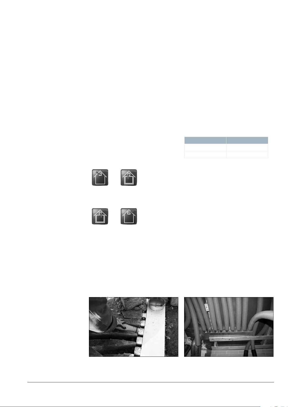
4 Positioning manifold
Position the manifold (if possible) in the immediate proximity of the Danfoss Air ventilation unit,
or determine its position based on an accompanying assembly drawing (if available).
An assembly drawing should be considered to
be a guide only; if the manifold in the drawing is
positioned unsuitably in relation to the construction or to other technical installations, move the
Manifold placed in insulating material
on the oor before casting.
manifold so that the installation is not unnecessarily hindered.
The manifold can be mounted on walls or the
ceiling, or cast in concrete slabs depending on
what is most appropriate in relation to routing.
Manifold positioned beneath
ceiling inside climate shield.
VI.FY.A2.02_Sep2014Instructions - Danfoss Air Flex
3
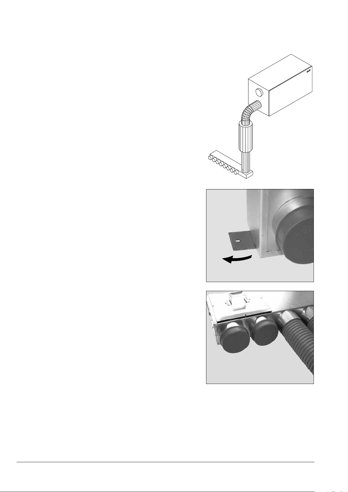
5 Mounting manifold
A silencer must be placed between ventilation unit and manifold - for supply as well as
for extract (only supply is illustrated).
The silencer should have the same diameter
as the connecting pipe on the ventilation
unit , and have a length of 600 mm.
Fasten the manifold using the two brackets
mounted beneath the base. Turn the
brackets and fasten them to the substrate.
If it is not possible to use the mounting
brackets, the manifold can be fastened with
metal strapping.
To prevent possible nuisance, place a soft
material (e.g. 2-3 mm of oor underlay)
between the metal strapping and manifold.
Close all unused spigots on the manifold
with a plastic plug, type DEC-77 (item no.
089 F0615).
4
VI.FY.A2.02_Sep2014 Instructions - Danfoss Air Flex
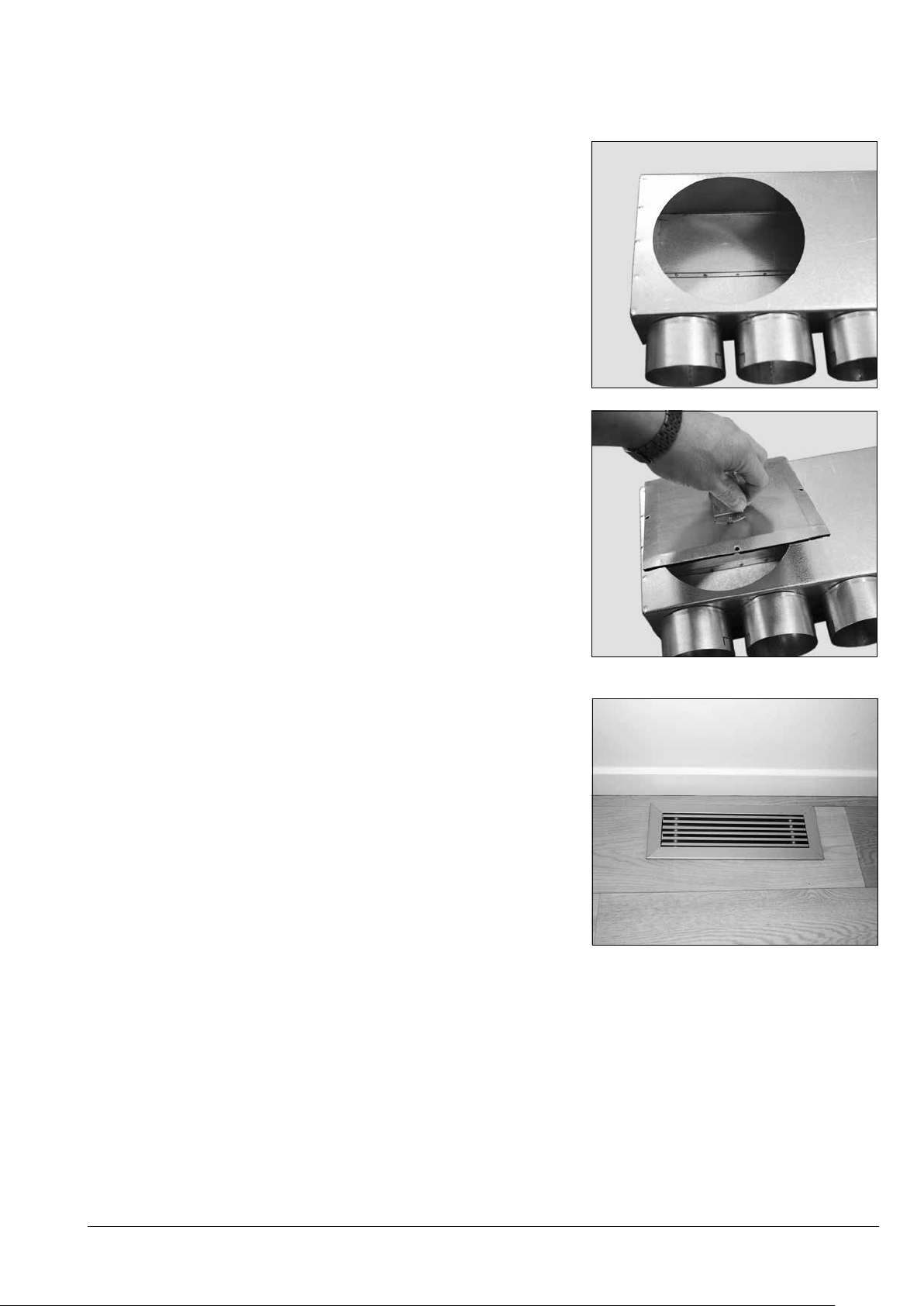
6 Mounting
inspection hatch
When mounting the inspection hatch, cut a hole
in the manifold where the inspection is to be
performed:
max. diameter 150 mm
max 150 x 150 mm
Place the inspection hatch, type DCH-150x150
(item no. 089F0643) over the hole and fasten
with 4 self-tapping screws.
7 Positioning
supply air box
on the oor
Supply air box and grill should ideally be
positioned against the wall at the following
locations:
• beneath a window
• beneath a radiator
• beside a replace/stove
To the extent possible, avoid placing the grill in
the following places:
• underneath furniture
• near places where people relax for longer
periods of time
If an assembly drawing is enclosed, use it for
guidance in positioning the box and grill.
Note!
Installing oor air extract is highly discouraged.
VI.FY.A2.02_Sep2014Instructions - Danfoss Air Flex
5

8 Mounting
supply air box
on the oor
Place the supply air box in insulation material so
that the distance to the top edge of the nished
oor can be adjusted with the telescopic collar
(collar can be extended by 100 mm).
220 - 320 mm
Fasten the box with the two brackets mounted
beneath the base. Turn the brackets and fasten
them to the substrate.
Mount an o-ring in the second groove on the
Flex pipe.
Mount the Flex pipe on the box.
6
VI.FY.A2.02_Sep2014 Instructions - Danfoss Air Flex

When the pipe is in place, fasten it by folding at
least two of the four cut-outs in with a screwdriver or the like.
Close unused spigots on the box and manifold
with a plastic plug, type DEC-77 (item no.
089F0615).
VI.FY.A2.02_Sep2014Instructions - Danfoss Air Flex
7

9 Before casting
What follows is an example of how a oor box
can be mounted.
The drawing shows the structure of an example
solution.
Note!
A majority of the following photos are staged.
Lead the Flex pipe from underneath the
insulation material.
The recommended distance between the stand
and insulation layer is 300 mm.
Concrete
Insulation material (EPS)
Sand
Place a piece of EPS over the pipe ends before
casting. Fasten to ensure that the position is
maintained during casting.
In this example, two pieces of soft steel are used
for the fastening.
After casting, remove the fastened insulation
material and mount the oor box.
8
VI.FY.A2.02_Sep2014 Instructions - Danfoss Air Flex

To fasten the oor box, use the two pre-mounted
brackets.
Before post-casting around the box, raise the
telescoping collar to a level just above the
nished oor height.
Tape the passage between the telescoping collar
and the box itself.
Tape a piece of insulation material in the box’s
opening.
Finally, ll the area around the box with insulation material, and cast in place.
When the concrete is dry, the telescoping collar
can be loosened with a light blow and then
lowered all the way down into the nished oor.
In some cases, it may be easier to ll all or part of
the hole with light expanded clay aggregate
mixed with concrete.
This will help prevent the relatively small pieces
of insulation material from oating on the
concrete during casting.
VI.FY.A2.02_Sep2014Instructions - Danfoss Air Flex
9

When the nished oor has been laid, pull out
the box’s adjustable insert and click the grill in
place by using the 4 leaf springs.
Place the grill in the insert and press the grill in
place evenly on both sides.
If a damper is selected for the grill, mount it
beneath the grill by using the pre-mounted clips.
The nished result.
For wall mounting use a DPGW box, which is
smaller and therefore ts in most inner walls. All
physical dimensions of the DPGW box are listed
in the Danfoss Air Flex product catalogue.
To fasten the grill and mount the damper, use
exactly the same method as for oor mounting.
10
VI.FY.A2.02_Sep2014 Instructions - Danfoss Air Flex

10 Positioning of valves
on wall and ceiling
The box and valves should be positioned in
accordance with the room’s function and design.
The supply valve should preferably be positioned:
• near a replace/stove (if present)
• near a window
• above a radiator
To the extent possible, avoid placing supply
valves directly over areas where people may be
located for longer periods of time, i.e. above
beds, sofas, dining tables, etc.
The extract valve should be mounted in ‘wet’
rooms, e.g. the kitchen, bathroom and utility
room.
If possible, the valve should be positioned where
moisture develops, i.e. near showers, sinks, etc.
If an assembly drawing is enclosed, it should be
used as a guide for positioning the box and
valve.
Note!
Please be aware that there is a dierence
between supply and extract valves.
11 Mounting valves
on wall and ceiling
Mount the box so that the spigots to the valve
are even with the nished wall/ceiling.
The valve can then be pushed in place in the box
(a supply valve is shown here).
Correct valve placement.
VI.FY.A2.02_Sep2014Instructions - Danfoss Air Flex
11

12 Mounting
Flex pipe
Floor mounting
Cut/furrow a route for the pipes in the insulation
material. The width of the route should be
adjusted to ensure a secure installation of the
pipe.
If it is not possible to t the pipes into furrows in
the insulation material, they can be fastened to
the Rionet.
The maximum distance between the fastening
points/strips is 50-70 cm.
To attain the greatest possible seal in the system,
mount an o-ring at each end of all pipes. Place
the o-ring in the second groove from the end
before mounting the pipe in the desired
manifold, box or coupler.
The pipes can then be mounted in the manifold.
When the pipe is in place, fasten it by folding at
least two of the four cut-outs in with a screwdriver or the like.
12
VI.FY.A2.02_Sep2014 Instructions - Danfoss Air Flex

To keep concrete, building dust or other material
from soiling the pipes during mounting, close all
unused spigots.
If the system is not used immediately after
installation, the pipes must be sealed to prevent
the accumulation of moisture. The pipes can be
sealed with a plastic plug, type DEC (089F0613),
or by closing the valves/grills.
To the extent possible, avoid making ‘sharp’
bends on the pipe, as this will increase the
system pressure loss.
Note!
When all pipes are mounted, thoroughly clean the manifold via the connecting pipe.
Wall/ceiling mounting
Wall mounting is recommended exclusively for
internal partitions to prevent thermal bridges
and penetrations of the climate shield.
For ceiling mounting, we also recommend
mounting the pipes inside a climate shield. If this
is not possible, the climate shield/damp-proof
membrane must be thoroughly sealed with
weather-resistant tape or the specially developed membranes shown here.
For systems with geothermal surfaces, the
supply pipe must be insulated with at least 30
mm of insulation material due to the risk of
external condensation on the pipes.
If the enclosed mounting brackets cannot be
used, metal strapping can be used to fasten the
boxes.
It is important that the pipes are fully extended
before tting to minimise pressure loss in the
system.
VI.FY.A2.02_Sep2014Instructions - Danfoss Air Flex
13
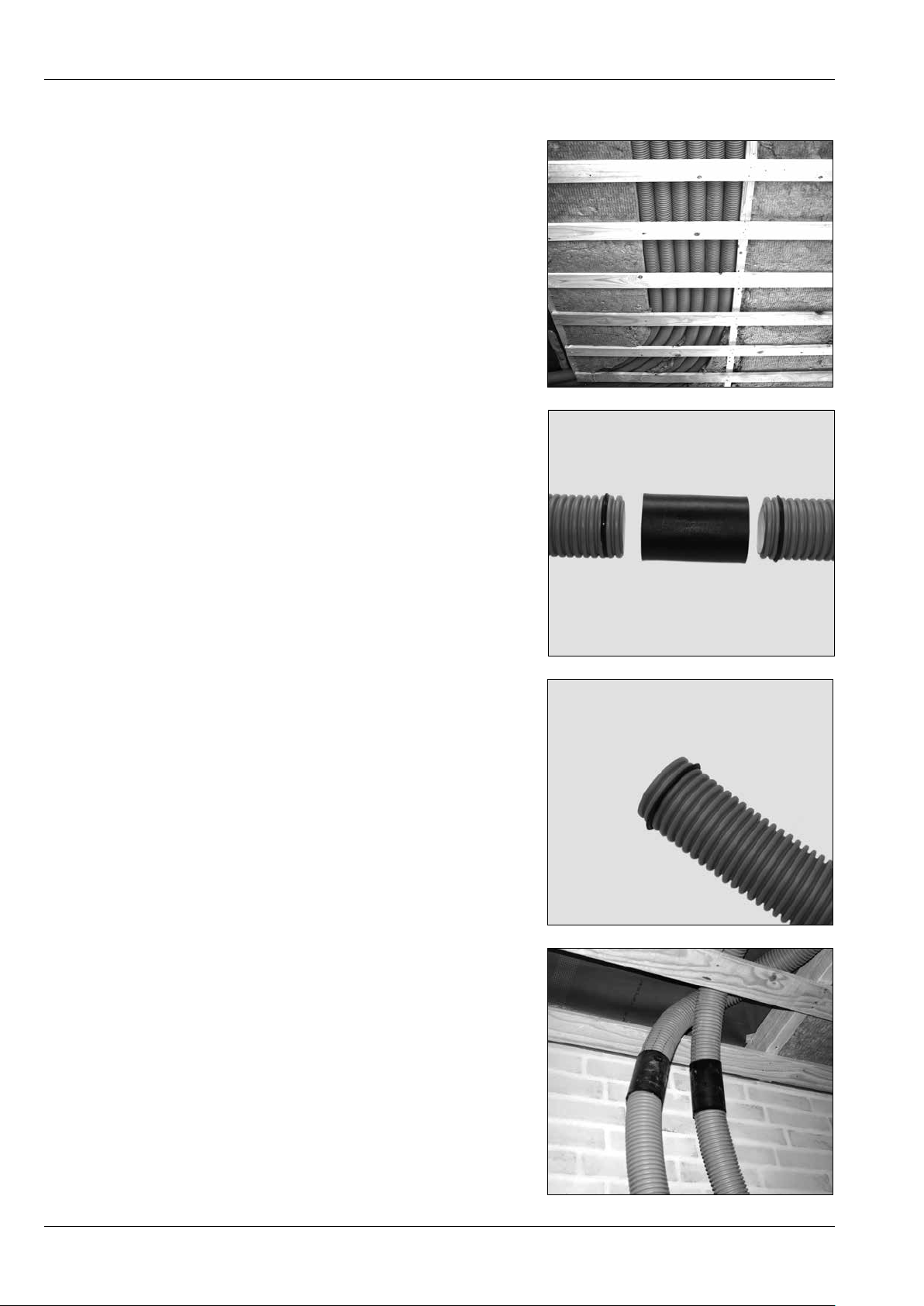
Here we see six correctly laid pipes beneath the
ceiling on the inside of the climate shield.
When the ceiling is set up, the length of the
screws must be adjusted so that they do not penetrate the pipes.
Connecting pipes in the coupling
If it is necessary to extend or simply connect two
pipe ends, this can be done using a coupling,
type DPC (089F0607).
Connect an o-ring in the second groove to both
pipes that are to be connected.
Completed couplings.
14
VI.FY.A2.02_Sep2014 Instructions - Danfoss Air Flex

13 Insulation
It is important that the entire Danfoss Air Flex
system is thoroughly insulated to minimise heat
loss and prevent condensation.
We recommend insulating pipes with at least 100
mm of insulation against cold surfaces.
14 Sound-damping the
system
15 Positioning roof termi-
nals and wall grills
Sound-damping the system is important for
general comfort and wellbeing.
Between the unit and manifold, mount a silencer
with a length of 600 mm to reduce any noise that
might otherwise be capable of spreading
Roof terminals/wall grills are the visible part of
the ventilation system from the outside. To the
extent possible, they should therefore always be
adapted to the architectural style of the house.
We recommend positioning the terminals at least
3 metres apart measured vertically or 1 metre
apart measured horizontally, always with the
outlet terminal at the top.
We also recommend placing terminals and grills
on a north-facing or east-facing surface for
optimal comfort.
through the rest of the system and throughout
the home.
In some cases, it might also be advisable to
mount silencer at the outlet and air inlet ends.
Note!
The outlet should be positioned:
- above the house’s top window
- at least one metre from the closest window
3 m
3 m
1 m
VI.FY.A2.02_Sep2014Instructions - Danfoss Air Flex
15

For generations now, Danfoss has been
delivering solutions used in all aspects of
heating and cooling , such as valves, thermostats,
pumps and highly advanced control systems.
The Danfoss Group cons ists of a global network
of sales companies, agents and distributors, and
Danfoss produc ts are sold, serviced and valued
around the world. Danfoss products also play
an important role when it comes to creating
optimal indoor climate and comfort.
Danfoss A/S
Ulvehavej 61 • DK-7100 Vejle • Denmark
Tel. +45 88 85 00 • Fax +45 74 88 86 03 • air@danfoss.com • www.danfoss.com • www.air.danfoss.com
This has always been our legacy, and the new
Danfoss Air system is set to carry on this proud
tradition.
www.danfoss.comVI.FY.A2.02_Sep2014
 Loading...