

Danfoss Air w1, Air a3, Air a2, Air w2 Installation Manual

MAKING MODERN LIVING POSSIBLE
Installation Guide
Danfoss Air Units
www.heating.danfoss.com

Danfoss A/S is not liable or bound by warranty if these
instructions are not adhered to during installation or service.
The English language is used for the original instructions.
Other languages are a translation of the original instructions.
(Directive 2006/42/EC)
© 2014 Copyright Danfoss A/S

Installation Guide
GB .
Installationsvejledning
Installationshandbuch
Instrukcja montażu
DK .
DE .
PL .

Installation Guide Danfoss Air Units
Table of Contents
1 Safety Note .................................................................... 2
2 Before Start .................................................................... 2
3 Installation of Air Units ............................................................ 3
4 Installation of CCM Module and Air Dial ................................................. 4
4.1 Electrical connections .......................................................... 4
4.2 Wireless connection ........................................................... 4
4.3 Air Dial .................................................................... 4
4.4 Mounting and removing CCM module and Air Dial ........................................ 5
5 Connecting to Danfoss Link™ CC ...................................................... 5
5.1 Connecting the Air Unit to Danfoss Link™ CC, physical installation .............................. 5
5.2 Connecting the Air Unit to Danfoss Link™ CC, wireless inclusion ............................... 6
5.3 Performing a network test after adding a new device ...................................... 6
5.4 Setting basic steps in the Danfoss Link™ CC ............................................ 7
6 Balancing of the Main Air Volume ..................................................... 7
7 Service Menu ................................................................... 8
8 Technical Specifications ............................................................ 9
8.1 a² Unit .................................................................... 9
8.2 a³ Unit .................................................................... 11
8.3 w¹ Unit .................................................................... 13
8.4 w² Unit .................................................................... 15
9 Troubleshooting ................................................................. 16
1 Safety Note
This appliance is not intended for use by persons (including children) with reduced physical, sensory or mental capabilities, or lack of
experience and knowledge, unless they have been given supervision or instruction concerning use of the appliance by a person responsible for their safety.
Children should be supervised to ensure that they do not play with the appliance.
Apart from the replacement of air filters and exterior cleaning of the system, any kind of maintenance will require the use of trained
personnel.
2 Before Start
Check the Danfoss Air Unit packing list to ensure that the shipment is complete.
If a complete Danfoss Air Solution is ordered, a packing list for the Air Flex duct system is included.
Inspect to ensure that no parts or components have been damaged.
Standard delivery includes:
Danfoss Air Unit
▪
Wall bracket (if w-model)
▪
CCM
▪
Cabels
▪
Optional deliveries:
Air Dial
▪
▪
Danfoss LinkTM CC
2
VIEWB302 Danfoss Heating Solutions
2
4
1
2
3
4
5
6
1
1 cm
2
3
5
75 mm
1
2
3
4
5
6
Installation Guide Danfoss Air Units
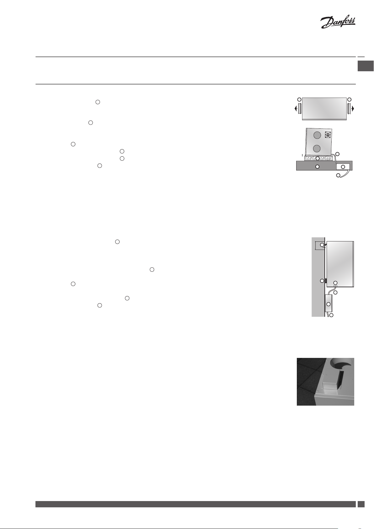
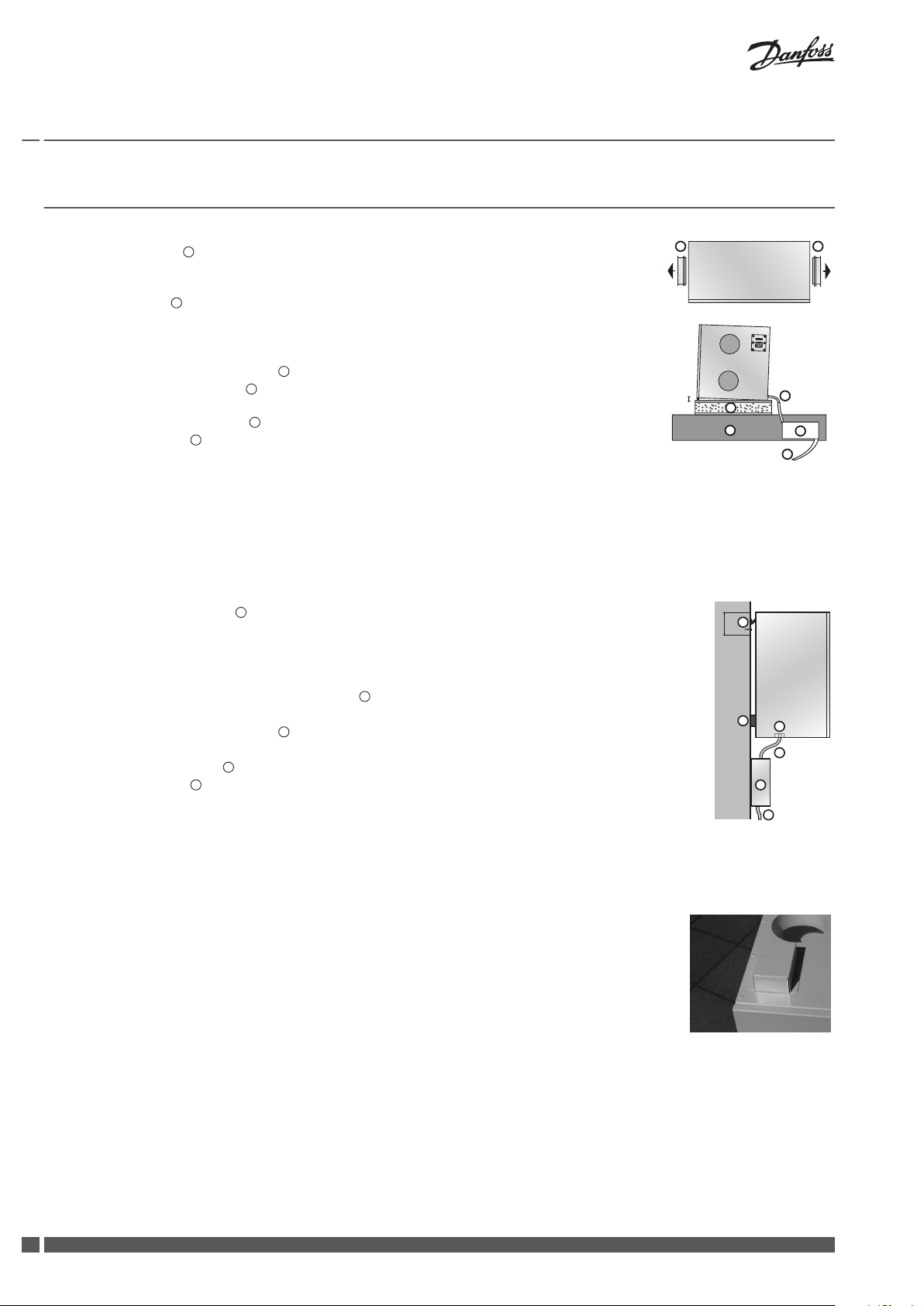
3 Installation of Air Units
Attic Units a² and a³
1. Pull out the spigots 1. Never lift the unit into the spigots, as it can damage the unit.*
2. Turn the spigots around and mount them using the included tapping screws (for power drill,
use lowest torque setting).
3. Make a platform
4. Allow for 60 cm free space in front of unit, to assure service access.
5. Make sure the unit is mounted with a minor backward fall.
6. A siphon 5 must always be installed with the unit (to be ordered separately).
7. Mount the siphon on the joist
8. Connect the siphon to a drain 6.
9. The condensate line 3 must be insulated where risk of freezing occurs.
10. Connect the hose to the unit outlet condensate spigot. Lead the connected pipe to the outlet, allowing for a gradient of min. 1 cm/metre.
11. Remove the front panel and foam front, fill the condensate tray, check the outlet and reassemble the front.
* If the unit is lifted into the spigots, it might cause leakage between the steel cabinet and the polystyrene core. The leakage can be fixed from the inside of the unit by sealing the spigots with an acrylicbased sealant.
for the unit of 16 mm plywood or MDF sheet around 50 mm wall batts.
below the unit or in the room below the attic.
GB .
Wall Units w¹ and w²
1. Place the mounting bracket 1 on the wall in desired position (75 mm from bracket bottom to
unit top), mark up and drill holes. Use screws suitable for the wall surface (not included).
2. Make sure that the bracket is mounted absolutely horizontal.
3. Hang the unit onto the bracket.
4. Attach the self-adhesive rubber separators
to the lower rear back plate.
5. Allow for 60 cm free space in front of unit, to assure service access.
6. A siphon
must always be installed with the unit (to be ordered separately).
7. Mount the siphon on the wall below the unit.
8. Connect the siphon to the drain
at the unit bottom.
9. The condensate line 4 must be insulated where risk of freezing occurs.
10. Connect the hose to the unit outlet condensate spigot. Lead the connected pipe to the outlet, allowing for a gradient of min. 1 cm/metre.
11. Remove the front panel and foam front, fill the condensate tray, check the outlet and reassemble the front.
Wall Unit w¹
In order to comply with safety standards and avoid the risk of malfunction, the supplied protection shield must be mounted on top of the w¹-unit covering the connector plate.
Danfoss Heating Solutions VIEWB302
3
1
2
3
4
5
6
1
2
3
4
!
Installation Guide Danfoss Air Units
4 Installation of CCM Module and Air Dial
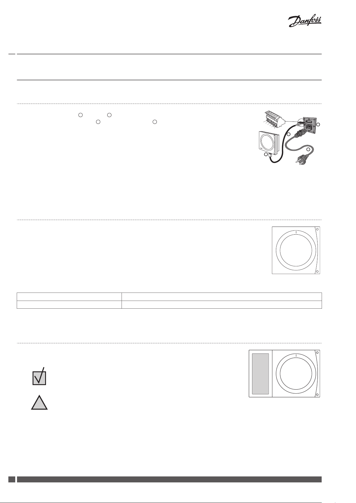
4.1 Electrical connections
1. Connect power cable 4 to Air unit 3.
2. Plug in communication cable 2 between CCM module 1 and Air unit.
3. Check the signal. If it is too weak, the CCM module should be placed elsewhere, e.g. on the
same floor as as the Air Dial (see Air Dial Link Test).
4. If possible, place the CCM module close to an ethernet connection for future connection to
PC.
5. If accessories (electrical preheating, electrical afterheating, water heating surface or geothermal surface) are present, the pin on terminals 5 and 6 must be removed (also see the
instructions included with the accessories).
Communication cable connections:
1. White/Orange, 2. Orange, 3. Black, 4. White/Blue, 5. Blue, 6. Black
Note! The communication cable can be extended up to 200 m. Use shielded cable , 22 or 24 AWG with 2 x twisted pair.
4.2 Wireless connection
When powering up the CCM module a green LED will flash slowly, indicating the CCM module
has yet to be connected to the Air Dial.
To connect the Air Dial, insert the batteries. The Air Dial starts in installation mode and automatically guides through the set-up.
1. Set language.
2. Create network (press button on CCM module and then press Air Dial).
3. Set basic step (setting up the main air volume).
4. Finish.
Green LED lights continuously Connected established
Red LED flashes slowly 5 times Connection attempt failed, see Troubleshooting.
Tab. 2: LED blink patterns on the CCM
4.3
Air Dial
The Air Dial has an integrated temperature sensor. To ensure best possible performance,
place the Air Dial according to following guidelines:
Place the Air Dial 80-150 cm above floor level.
▪
Place the Air Dial free of curtains etc.
▪
Place the Air Dial where the temperature is representative.
▪
Do not place the Air Dial in bathrooms.
▪
Do not place the Air Dial in direct sunlight.
▪
Do not place the Air Dial onto outer wall.
▪
Do not place the Air Dial directly above heat source.
▪
4
VIEWB302 Danfoss Heating Solutions
2
1
2
1
1
1
2
1
2
1
2
3
4
5
6
1
2
3
4
Installation Guide Danfoss Air Units
Air Dial Link Test
Before mounting the Air Dial permanently, perform a link test to ensure that transmission conditions are sufficient for the required location:
1. Press the Air Dial button for 5 seconds to access the Service Menu (The Service Menu remains visible for one hour).
2. Select the Link Test function.
3. The function shows if the transmission conditions are sufficient or not.
4. If the link test fails, see Troubleshooting.
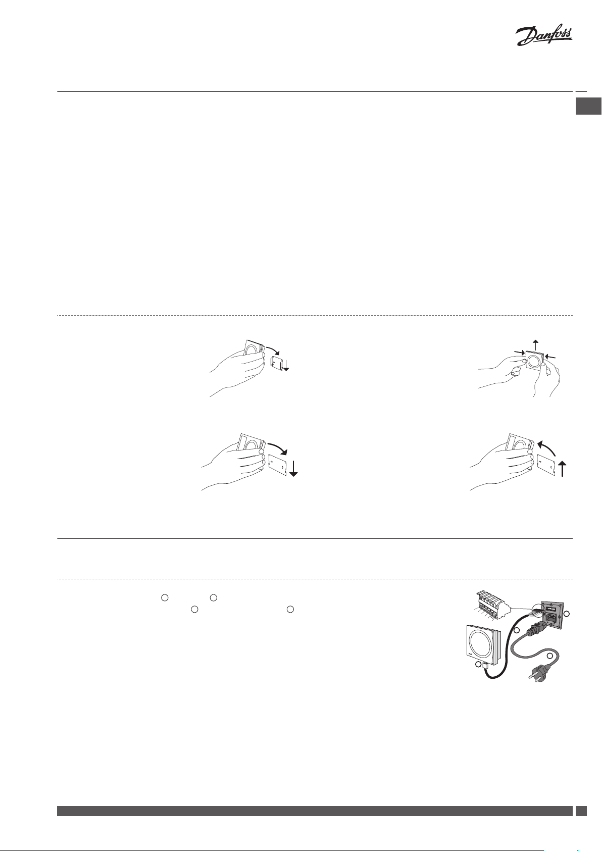
4.4 Mounting and removing CCM module and Air Dial
CCM module
Mounting:
1. Place the CCM on the wall
bracket.
2. Press downwards to click the
CCM into place.
Removing:
1. Press in the two latches on the
side.
2. Pull the CCM upwards.
GB .
Air Dial
Mounting:
1. Place the Air Dial on the wall
bracket.
Removing:
1. Lift the Air Dial.
2. Pull the Air Dial away.
2. Press downwards to click the
Air Dial into place.
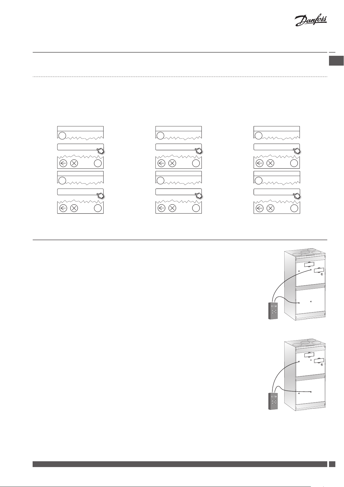
5 Connecting to Danfoss Link™ CC
5.1 Connecting the Air Unit to Danfoss Link™ CC, physical installation
1. Connect power cable 4 to Air unit 3.
2. Plug in communication cable 2 between CCM module 1 and Air unit.
3. If possible, place the CCM module close to an ethernet connection for future connection to
PC.
4. If accessories (electrical preheating, electrical afterheating, water heating surface or geothermal surface) are present, the pin on terminals 5 and 6 must be removed (also see the
instructions included with the accessories).
5. The Air Unit is now ready to be added to the Danfoss Link™ CC.
Communication cable connections:
1. White/Orange, 2. Orange, 3. Black, 4. White/Blue, 5. Blue, 6. Black
Note! The communication cable can be extended up to 200 m. Use shielded cable , 22 or 24 AWG with 2 x twisted pair.
Danfoss Heating Solutions VIEWB302
5
?
1
Service Options
Rooms and Devices
?
2
Rooms and Devices
Add Service Devices
?
3
Add Service Device
Begin Registration
?
1
Service Options
Status and Diagnostics
?
2
Status and Diagnostics
Network
?
3
Wireless Network Status
Start Network Test
Installation Guide
Danfoss Air Units
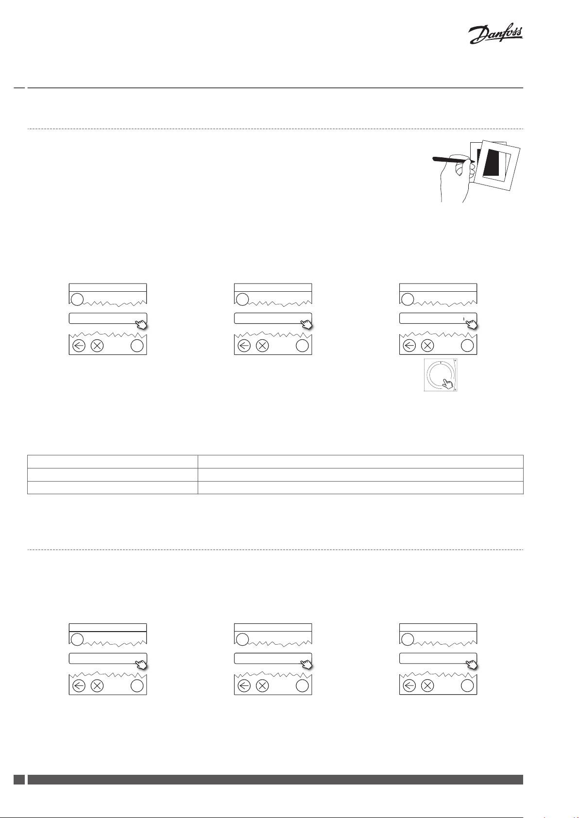
5.2 Connecting the Air Unit to Danfoss Link™ CC, wireless inclusion
Remove the front cover of the Danfoss Link™ CC by gently pulling it off, pull near the
▪
edges of the cover.
Press the SETUP pin for 3 seconds to enter the service area.
▪
Note!
The Air Unit must be added to the network as a service device. For further instructions on the network inclusion, see the installation guide
▪
supplied with the Danfoss Link™ CC.
Add any dedicated repeater units (CF-RU) BEFORE adding the Air Unit to the wireless network.
▪
Click here on the CCM for adding the Air
Unit
Note! During installation, the distance between the Danfoss Link™ CC and the CCM must not exceed 1.5m.
Green LED flashes slowly
CCM module has not yet been connected to the Danfoss Link™ CC
Green LED lights continuously CCM module is now connected to the Danfoss Link™ CC
Red LED flashes slowly 5 times Connection attempt failed
Tab. 2: LED blink patterns on the CCM
5.3
Performing a network test after adding a new device
After finishing installation, perform a network test, to ensure that communication between added devices and the Danfoss Link™ CC is
stable.
Note! Do not perform the network test before the Danfoss Link™ CC is mounted in its final position.
At the end of the network test the Danfoss Link™ CC awaits for all battery operated devices to wake up and report. Follow the instructions given on the screen. If the network test is running smoothly, there will be no need for further interaction. If the network test is
performing slow, the Danfoss Link™ CC guides through troubleshooting and gives usefull tips for speeding up the process.
6
VIEWB302 Danfoss Heating Solutions
?
1
Service Options
Rooms and Devices
?
2
Rooms and Devices
Manage Devices
?
3
Manage Devices
Congure device
?
4
Select Device
Air unit
?
5
Congure Device
System settings
?
6
System settings
Set basic steps
Installation Guide Danfoss Air Units
5.4 Setting basic steps in the Danfoss Link™ CC
Now the Air Unit has been added to the wireless system, and is ready for balancing of the air flow. If the Air Unit has just been added to
the system, the screen will prompt for setting the basic extract and supply air step.
If the system was started earlier/by others, enter the basic settings through the Service Menu by pressing the Air Dial button for 5 seconds. Go through the following steps.
GB .
6 Balancing of the Main Air Volume
To achieve the best possible performance, it is vital to balance the main air volumes (balancing
will also help protecting the house against fungus and dry rot). The system should not be balanced/commisioned at outdoor temperatures below -3°C, as the system will go into frost protection mode (indicated by a flashing icon on the display. If necessary to perform balancing at
outdoor air temperatures below -3°C, remove power for 20 seconds to de-activate frost protection for 90 minutes.
Note! Close all doors and turn off the cooker hood.
1. Remove the front panel from unit by pulling the handles.
2. See the drawing of the duct system, where suggested pre-setting values for all air valves
are stated. Close the valves completely, and turn them full turns towards open (number of
turns as indicated on the duct system drawing). When setting up the systems for which
Danfoss has not dimensioned the duct system, set the supply and extract valves in accordance with the instructions of the project manager.
3. If dampers are included in the system, open these completely.
4. Mount measuring tubes between the unit’s measuring points on the extract side and differential pressure gauge.
5. Find the required flow on the system diagram (sticker on front cover) with the corresponding differential pressure value. If the pressure is too low, adjust the fan step upwards until
you reach the required pressure.
6. Move the measuring tubes to the measuring points on the supply side and use the same
procedure to set the supply air.
7. After the main air volumes have been adjusted, the set-up of individual valves needs to be
carried out. In most cases, this will entail minor changes to the chosen basic steps, but this
can be done in the room by adjusting the valves, or by using the Air Dial to fine tune basic
steps.
Measuring the extract
Adjusting an operational system
1. Press Air Dial for 5 seconds to get access to the Service menu.
2. Press ”set basic step” to activate the special commissioning mode (where all outside influences are blocked - the installer controls the extract and supply air fans completely with
1-100% fan speed). The Service menu remains visible for one hour and then disappears.
Danfoss Heating Solutions VIEWB302
Measuring the supply
7

Service
Back
Info
Set filter timer
Set language
Set basic step
Link test
Accessories
Installation Guide Danfoss Air Units
7 Service Menu
Press Air Dial for 5 seconds to access the Service Menu to change basic settings like language,
filter timer, basic steps etc.
System Reset
1. If the system has already been balanced, make a note of the basic fan steps for later use.
The values are found in the Service Menu: Service > Info > Basic Steps.
2. Remove and re-insert the Air Dial batteries while pressing the button until a beep is heard.
The Air Dial is now in start-up mode.
3. Remove the supply or communication cable.
4. While re-connecting the cable, press the CCM module button until only the green LED is
flashing.
5. The system is now reset to factory settings.
8
VIEWB302 Danfoss Heating Solutions
450
325
177
160
1263
1180
600
1
2
3
4
580
450
325
177
1
2
3
4
1
2
3
4
5
6
6
5
1
2
3
4
5
6
100%
85%
1000 J/m³
70%
58%
46%
33%
21%
350
300
250
200
150
100
50
0
0 50 100 150 200 250 300 350 400 450
*0.45 W/m³/h
83%
84%
85%
86%
87%
88%
89%
90%
91%
92%
93%
94%
0 50 100 150 200 250 300
Installation Guide
Danfoss Air Units
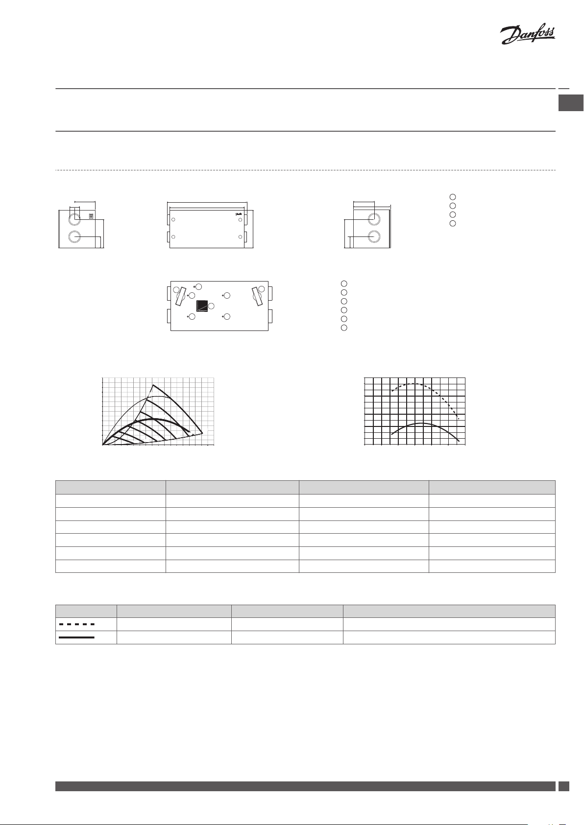
8 Technical Specifications
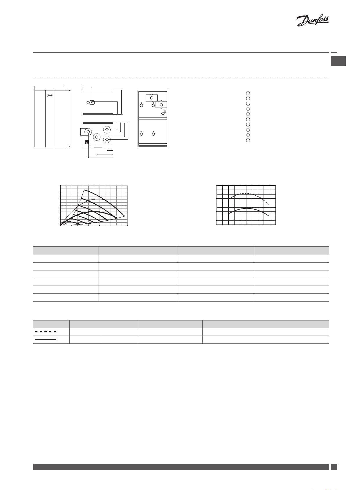
8.1 a² Unit
Dimensions
Front view (without front panel)
Filter, extract air
Filter, supply air
Flow chart (for balancing)
Filter reset button
Differential pressure for extract air
Differential pressure for supply air
GB .
Outdoor air
Exhaust air
Extract air
Supply air
Weight of unit: 52 kg
Capacity Temperature ratio
Pressure [Pa] η [%]
Flow [m³/h]
* 0.45 W/m³/h = "Passiv Haus" requirements.
Flow [m³/h] Pext. [Pa] SFP [J/m³] P1 tot. [W]
160 50 615 27
220 70 728 44
220 100 854 52
260 70 783 57
260 100 894 65
300 90 936 78
Tab. 3: Capacity for the a² unit
Extract air Fresh air
t = 21 °C RH = 36% t = -3 °C RH = 80% with condensation and 5% imbalance
t = 25 °C RH < 27% t = 5 °C as acc. to EN308
Flow [m³/h]
Tab. 4: Temperature ratio for the a² unit
Danfoss Heating Solutions VIEWB302
9

Installation Guide
Danfoss Air Units
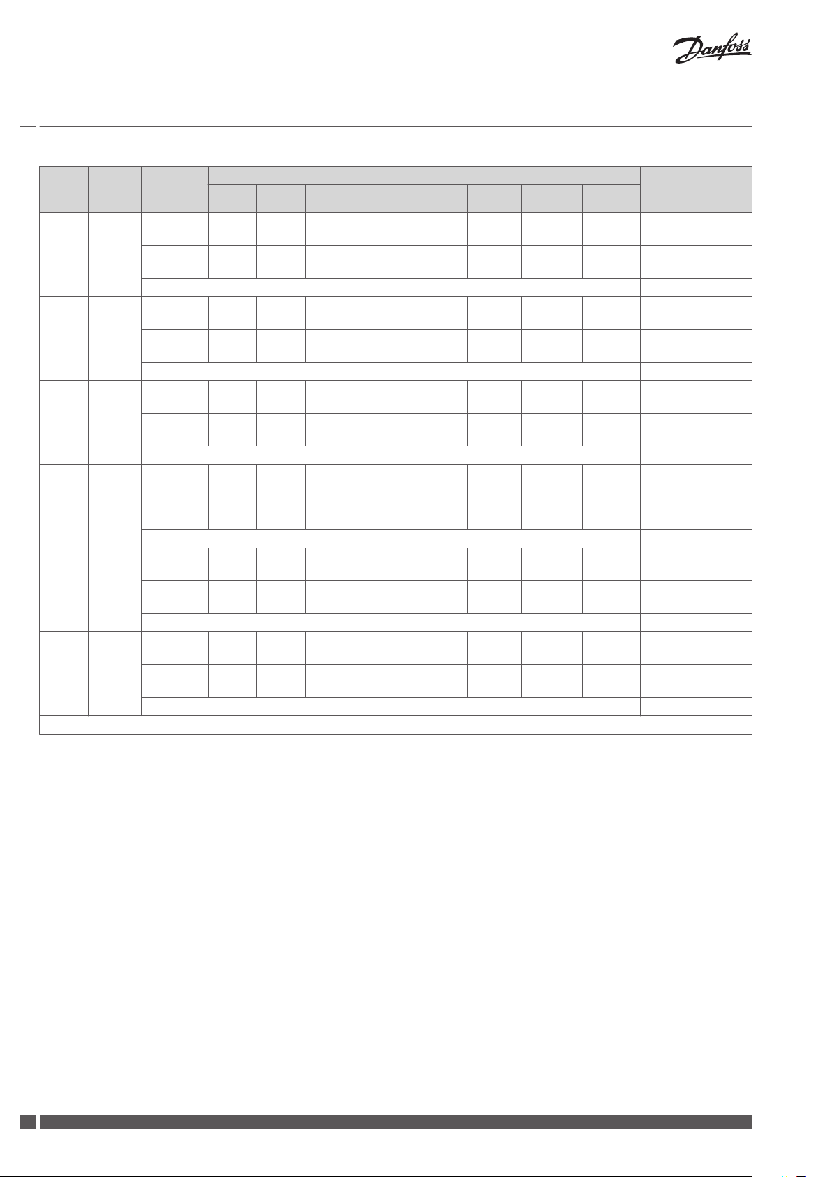
Flow
m³/h
162 70
162 100
216 70
216 100
250 100
* Values for sound pressure calculated for a standard room with A = 10 m², H = 2.4m and mean absorption 0.2.
Pres-
sure Pa
Measured
at
Supply air
duct
Extract air
duct
Cabinet 40
Supply air
duct
Extract air
duct
Cabinet 41
Supply air
duct
Extract air
duct
Cabinet 45
Supply air
duct
Extract air
duct
Cabinet 46
Supply air
duct
Extract air
duct
Cabinet 49
63 125 250 500 1000 2000 4000 8000
23 34 40 36 29 25 17 18
23 33 39 37 29 24 18 18
25 35 43 38 31 28 18 18
25 36 42 39 30 25 17 18
26 36 44 39 33 30 19 18
28 36 43 41 34 29 18 18
26 37 44 40 34 31 19 18
27 37 45 42 35 30 19 18
28 39 46 42 37 33 21 18
30 39 48 45 38 33 20 18
Frequency band [Hz], sound power Lw (A) [dB(A)] Sound pressure
Lp(A) (standard*
room) [dB(A)]
Tab. 5: Sound data for the a² unit
10
VIEWB302 Danfoss Heating Solutions
250
440
160
528
318
1180
1342
600
1
2
3
4
780
440
160
528
318
1
2
3
4
1
2
3
4
5
6
6
5
1
2
3
4
5
6
40%
56%
82%
100%
1000 J/m³
300
250
200
150
100
50
0
0 50 100 150 200 250 300 350 400 450 500 550 600
*0.45 W/m³/h
80%
81%
82%
83%
84%
85%
86%
87%
88%
89%
90%
0 50 100 150 200 250 300 350 400 450 500
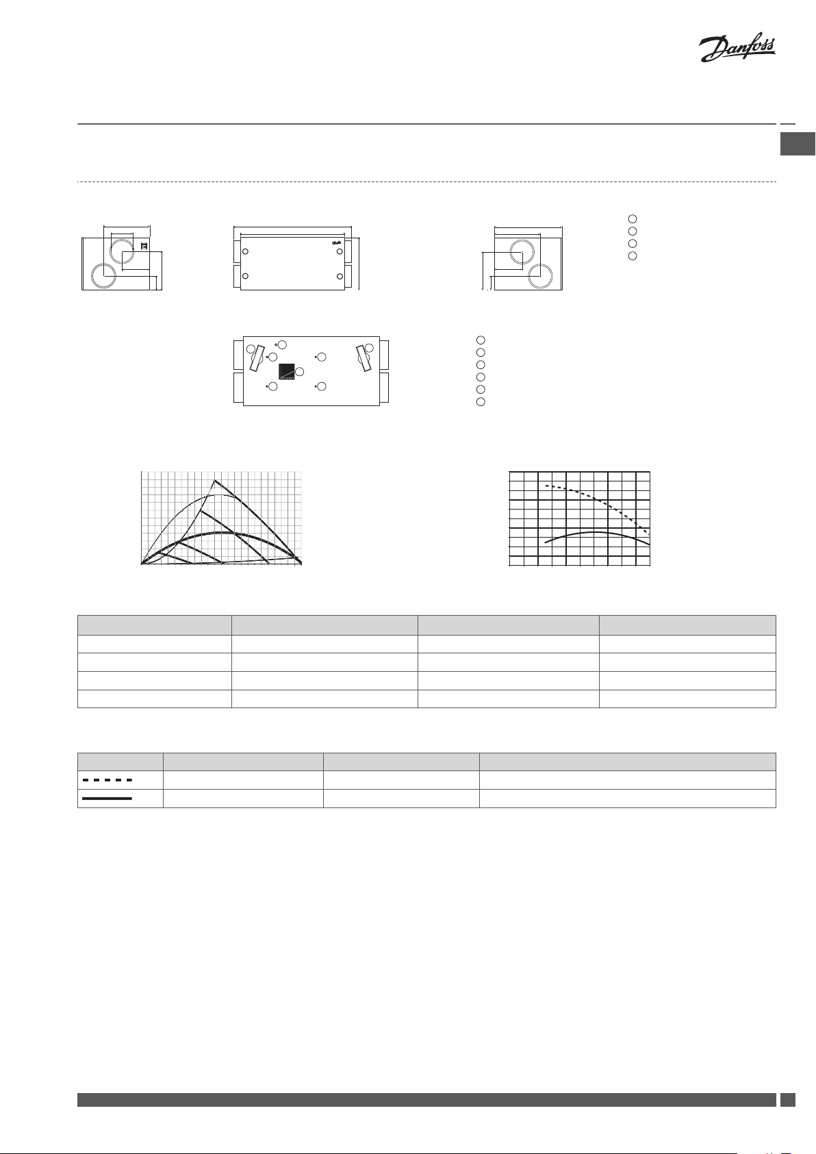
Installation Guide
Danfoss Air Units
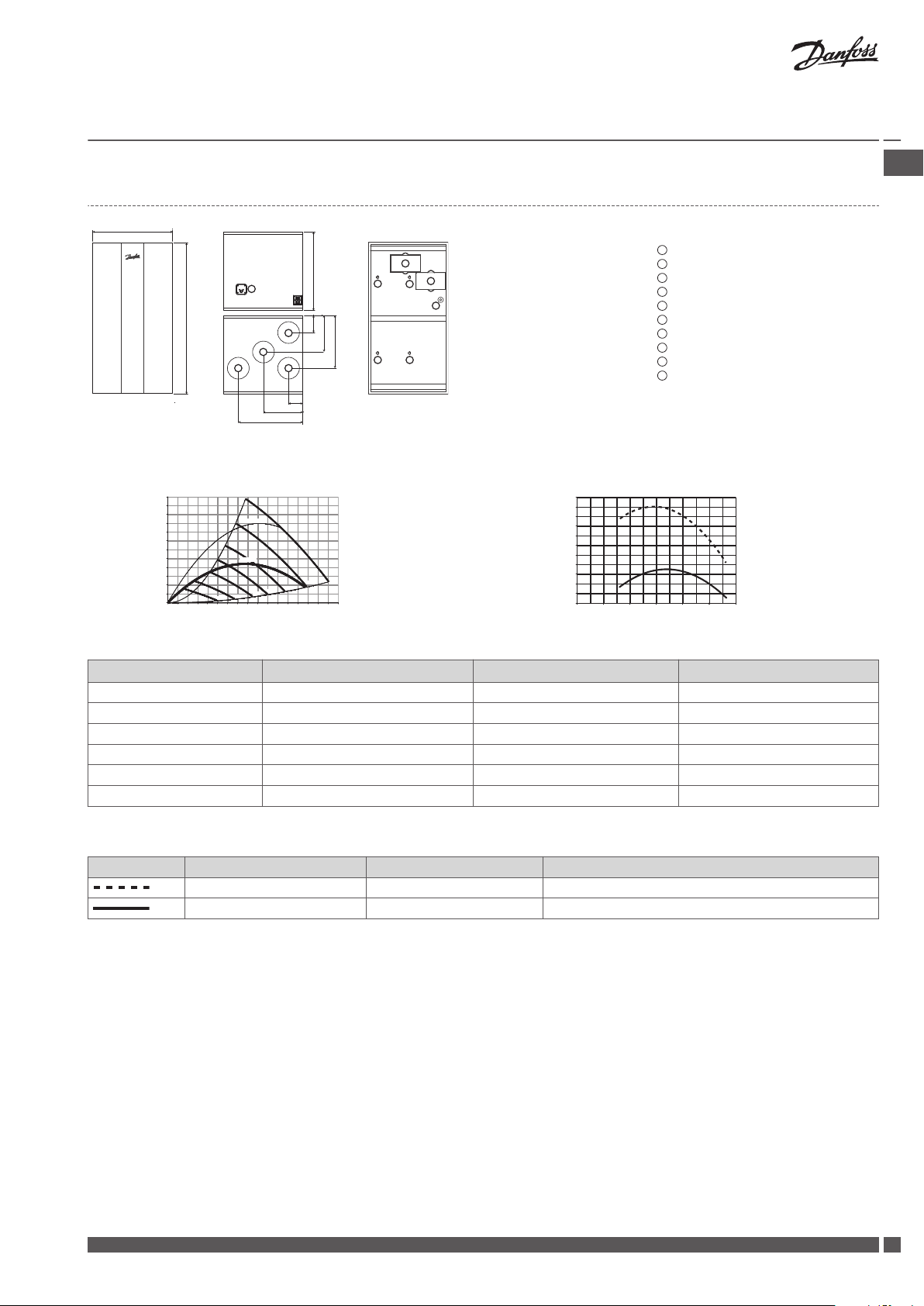
8.2 a³ Unit
Dimensions
Outdoor air
Exhaust air
Extract air
Supply air
Weight of unit: 67 kg
Front view (without front panel)
Capacity Temperature ratio
Pressure [Pa] η [%]
Filter, extract air
Filter, supply air
Flow chart (for balancing)
Filter reset button
Differential pressure for extract air
Differential pressure for supply air
GB .
Flow [m³/h]
* 0.45 W/m³/h = "Passiv Haus" requirements.
Flow [m³/h] Pext. [Pa] SFP [J/m³] P1 tot. [W]
200 70 787 44
350 70 835 81
450 70 973 122
350 100 1000 97
Tab. 6: Capacity for the a³ unit
Extract air Fresh air
t = 21 °C RH = 36% t = -3 °C RH = 80% with condensation and 5% imbalance
t = 25 °C RH < 27% t = 5 °C as acc. to EN308
Tab. 7: Temperature ratio for the a³ unit
Flow [m³/h]
Danfoss Heating Solutions VIEWB302
11
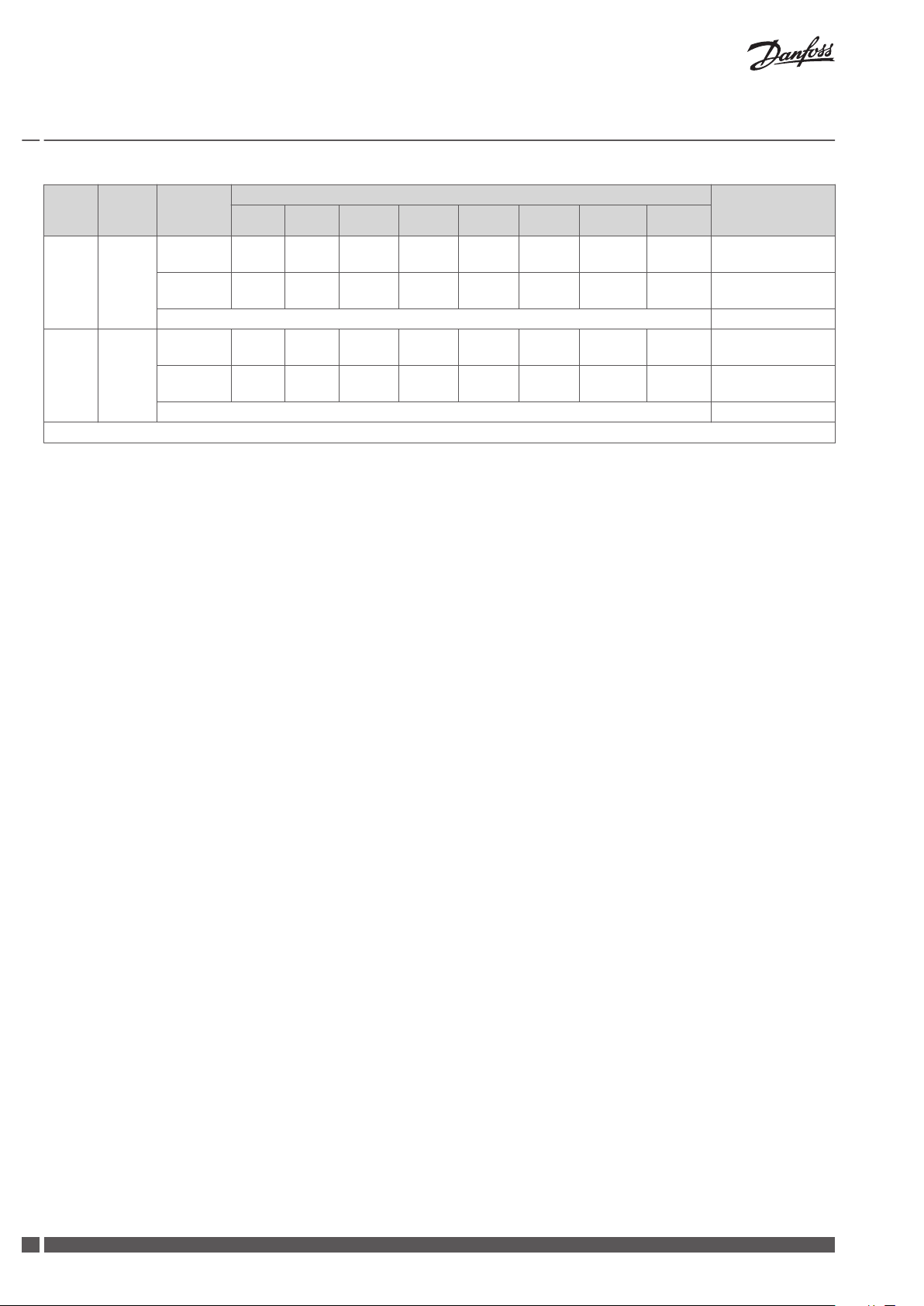
Installation Guide
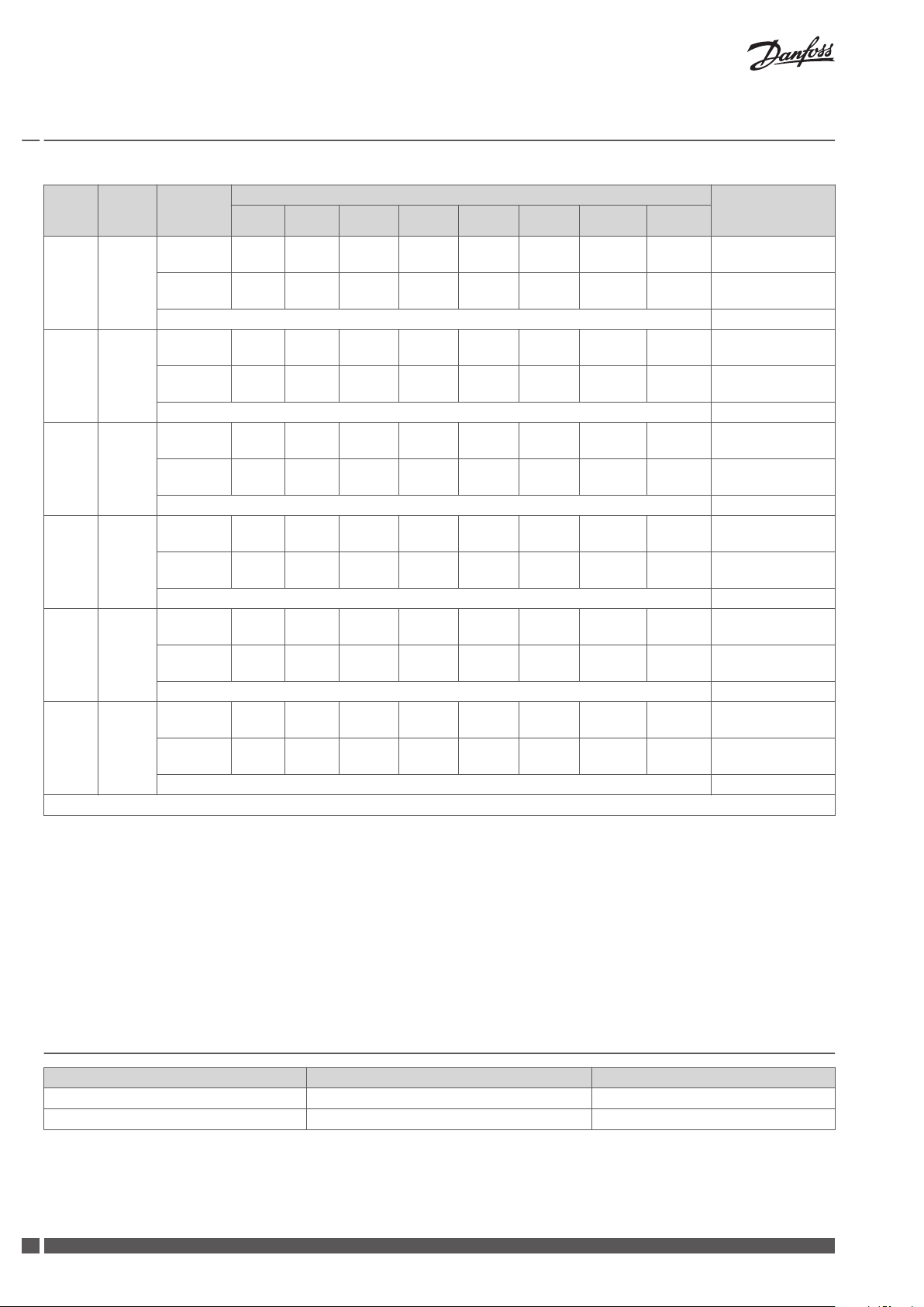
Danfoss Air Units
Flow
m³/h
350 70
450 100
* Values for sound pressure calculated for a standard room with A = 10 m², H = 2.4m and mean absorption 0.2.
Tab. 8: Sound data for the a³ unit
Pres-
sure Pa
Measured
at
Supply air
duct
Extract air
duct
Cabinet 57
Supply air
duct
Extract air
duct
Cabinet 61
63 125 250 500 1000 2000 4000 8000
35 45 56 49 47 44 31 16
35 44 54 48 48 44 31 19
39 48 62 55 52 50 37 22
39 47 61 55 53 48 37 20
Frequency band [Hz], sound power Lw (A) [dB(A)] Sound pressure
Lp(A) (standard*
room) [dB(A)]
12
VIEWB302 Danfoss Heating Solutions
530
1005
108
287
438
125
161
254
296
125
430
224
160
1
2
3
4
5
6
7
89
98
10
1
2
3
4
5
6
7
8
9
10
85%
70%
58%
46%
33%
21%
*0.45 W/m³/h
1000 J/m³
350
300
250
200
150
100
50
0
0 50 100 150 200 250 300
100%
84%
85%
86%
87%
88%
89%
90%
91%
92%
93%
0 50 100 150 200 250
Installation Guide
Danfoss Air Units
8.3 w¹ Unit
Supply air
Extract air
Exhaust air
Outdoor air
Condensate drain
Filter, extract air
Filter, supply air
Differential pressure for extract air
Differential pressure for supply air
Filter reset button
Weight of unit: 32 kg
Capacity Temperature ratio
Pressure [Pa] η [%]
GB .
Flow [m³/h]
* 0.45 W/m³/h = "Passiv Haus" requirements.
Flow [m³/h] Pext. [Pa] SFP [J/m³] P1 tot. [W]
100 35 588 16
100 55 682 19
140 60 710 28
140 70 759 30
180 70 798 40
180 100 945 47
Tab. 9: Capacity for the w¹ unit
Extract air Fresh air
t = 21 °C RH = 52% t = 5 °C RH = 80% with condensation and 5% imbalance
t = 25 °C RH < 27% t = 5 °C as acc. to EN308
Tab. 10: Temperature ratio for the w¹ unit
Flow [m³/h]
Danfoss Heating Solutions VIEWB302
13
Installation Guide
Danfoss Air Units
Flow
m³/h
126 70
126 100
162 70
162 100
216 70
216 100
* Values for sound pressure calculated for a standard room with A = 10 m², H = 2.4m and mean absorption 0.2.
Pres-
sure Pa
Measured
at
Supply air
duct
Extract air
duct
Cabinet 47
Supply air
duct
Extract air
duct
Cabinet 50
Supply air
duct
Extract air
duct
Cabinet 53
Supply air
duct
Extract air
duct
Cabinet 55
Supply air
duct
Extract air
duct
Cabinet 57
Supply air
duct
Extract air
duct
Cabinet 56
63 125 250 500 1000 2000 4000 8000
20 30 41 42 38 30 19 18
18 30 41 41 30 26 18 18
22 32 46 45 39 32 21 18
22 33 43 42 32 27 19 18
23 31 43 46 41 33 22 18
26 31 42 43 33 29 21 18
28 33 44 48 43 35 23 18
29 34 44 51 37 31 23 18
28 33 44 54 46 37 28 18
27 33 43 52 39 33 27 18
28 35 45 55 46 38 29 18
32 34 44 52 40 34 28 18
Frequency band [Hz], sound power Lw (A) [dB(A)] Sound pressure
Lp(A) (standard*
room) [dB(A)]
Tab. 11: Sound data for the w¹ unit
14
VIEWB302 Danfoss Heating Solutions
590
1055
580
126
270
389
110
295
480
1
2
3
4
5
6
7
8
9
98
10
1
2
3
4
5
6
7
8
9
10
100%
85%
70%
58%
46%
33%
21%
300
250
200
150
100
50
0
*0.45 W/m³/h
1000 J/m³
0 50 100 150 200 250 300 350 400
83%
84%
85%
86%
87%
88%
89%
90%
91%
92%
93%
94%
0 50 100 150 200 250 300
Installation Guide
Danfoss Air Units
8.4 w² Unit
Supply air
Extract air
Exhaust air
Outdoor air
Condensate drain
Filter, extract air
Filter, supply air
Differential pressure for extract air
Differential pressure for supply air
Filter reset button
Weight of unit: 45 kg
Capacity Temperature ratio
Pressure [Pa] η [%]
GB .
Flow [m³/h]
* 0.45 W/m³/h = "Passiv Haus" requirements.
Flow [m³/h] Pext. [Pa] SFP [J/m³] P1 tot. [W]
160 50 700 31
220 70 832 51
220 100 963 59
260 70 892 64
260 100 996 72
280 90 1000 78
Tab. 12: Capacity for the w² unit
Extract air Fresh air
t = 21 °C RH = 36% t = -3 °C RH = 80% with condensation and 5% imbalance
t = 25 °C RH < 27% t = 5 °C as acc. to EN308
Tab. 13: Temperature ratio for the w² unit
Flow [m³/h]
Danfoss Heating Solutions VIEWB302
15
Installation Guide Danfoss Air Units
Flow
m³/h
126 50
162 70
162 100
216 70
216 100
250 100
* Values for sound pressure calculated for a standard room with A = 10 m², H = 2.4m and mean absorption 0.2.
Pres-
sure Pa
Measured
at
Supply air
duct
Extract air
duct
Cabinet 39
Supply air
duct
Extract air
duct
Cabinet 44
Supply air
duct
Extract air
duct
Cabinet 46
Supply air
duct
Extract air
duct
Cabinet 47
Supply air
duct
Extract air
duct
Cabinet 49
Supply air
duct
Extract air
duct
Cabinet 53
63 125 250 500 1000 2000 4000 8000
20 30 34 36 23 19 17 18
16 31 37 36 29 21 17 18
23 33 35 40 32 24 18 18
20 33 44 39 34 26 18 18
25 36 42 42 34 28 18 18
21 33 43 41 35 28 18 18
25 34 42 42 35 28 19 18
22 34 44 43 37 31 20 18
26 36 43 44 36 30 20 18
23 34 45 44 33 32 20 18
27 36 45 45 38 31 21 18
24 37 47 45 40 34 22 18
Frequency band [Hz], sound power Lw (A) [dB(A)] Sound pressure
Lp(A) (standard*
room) [dB(A)]
Tab. 14: Sound data for the w² unit
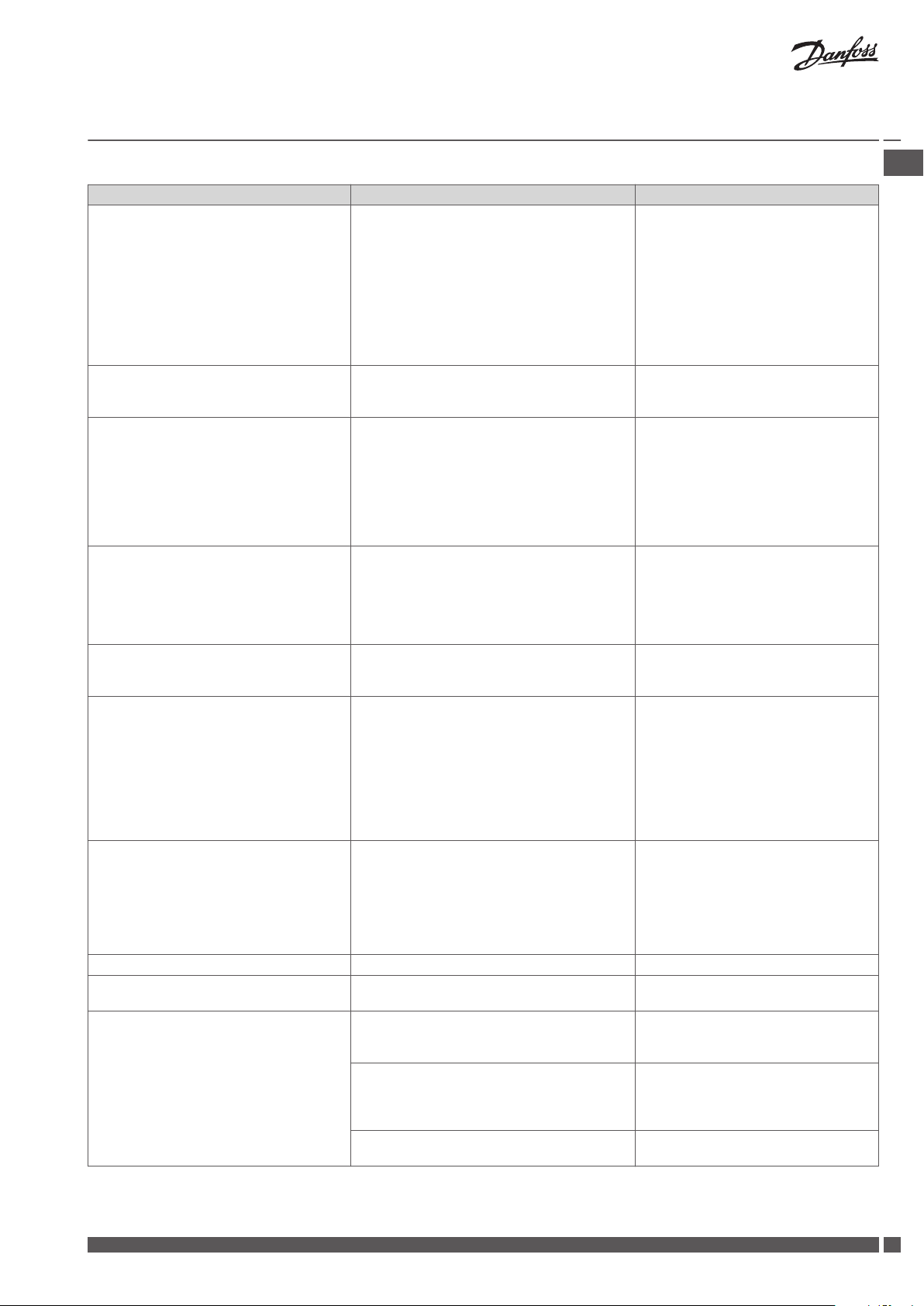
9 Troubleshooting
Error Cause Solution
Alarm: Filter error Air filters are dirty. Exchange air filters and reset alarm.
Alarm: Battery low Battery voltage in Air Dial is too low. Replace batteries (4 x AAA) in Air Dial.
16
VIEWB302 Danfoss Heating Solutions
Installation Guide Danfoss Air Units
Error Cause Solution
Alarm: No connection to CCM/link test
failed
Alarm: No connection via modbus/link test
failed
Alarm: Room air too cold Central heating system is not supplying heat.
Alarm: Fire One of four temperature sensors in Danfoss Air
Alarm: Sensor error Temperature sensor in Danfoss Air unit or Air
Abnormally large negative pressure inside
the house, doors binding
Condensation in window frames Air exchange is too low. Condensation occurs
House temperatures are too high House thermostats are set too high. Turn down thermostats.
Bypass is disabled on ventilation system. Bypass is disabled on ventilation system. Enable Bypass in Main menu Bypass
Noise from Air Unit a-type unit: vibration noise may occur if unit is
Communication between Air Dial and CCM
module has failed, typically caused by an obstacle between Air Dial and CCM module, e.g.
steel piping, other steel objects, insulation material clad with aluminum foil, etc. Another
cause can be other wireless appliances that
does not conform to wireless standards (radio
noise).
Cable between CCM module and unit is unplugged or defective.
Room temperature is dropping, so the unit
turn off to reduce involuntary heat loss. Alarm
active if Air Dial measures a room temperature
below +10 °C.
Unit or temperature sensor in Air Dial remote
control has detected a temperature higher
than +70 °C. The Air Unit turns off until all sensors indicate below +70 °C.
Dial is defective.
Discharge air flow is larger than supply air flow.
Either balancing was not carried out correctly
during set-up of the system or the Air Unit is in
extreme defrost conditions (can occur at outdoor temperatures below -12 °C).
when humidity is high and surface temperatures are low, typically in bathrooms or utility
rooms, where clothes are drip drying (some
condensation in bathrooms following a shower
is normal, but should disappear within half an
hour).
mounted directly onto joists. Unit should be
mounted on a suitable platform.
w-type unit: vibration noise may occur if rubber spacers are not fitted between unit and
wall and/or if silicone strip is not fitted onto
wall bracket.
Defective fan bearings will produce a ‘grinding
noise’.
If an obstacle has been identified, move
it. If this is not possible, move CCM
module to a better location with a free
‘line of sight’.
If the error occurs due to other wireless
appliances in the house, try switching
these off one by one, to identify the
faulty device.
If none of the above helps, contact Danfoss.
Check cable and reconnect if necessary.
If cable is connected, but error still occurs - contact Danfoss.
Check if heating system is functional. If
the problem can not be solved, contact
plumber/Danfoss.
When error has been remedied, shut
down and restart ventilation system to
resume normal operation. Power can be
disconnected by pulling power cable
from system.
Examine all rooms, leave the house.
When error has been remedied, shut
down and restart ventilation system to
resume normal operation. Power can be
disconnected by pulling power cable
from system.
Contact Danfoss.
System continues to run, but with limited functionality.
Imbalance of flow should be 4-10% in
favour of extract air, but if problems
with doors binding is permanent, contact Danfoss.
If problems only arises during extreme
winter condition, it is due to the integrated defrost function that reduces the
supply air (hence not a defect, but an
expected, and very rare occurrence).
Increase fan step Manual mode or
change to Demand mode or Pro-
gramme mode.
Set Autoboost - on.
Auto bypass.
Check that unit is mounted on platform,
according to installation manual.
Check that rubber spacers and silicone
strip are fitted, according to installation
manual.
If fan ball bearing is suspected to be defective, contact Danfoss.
GB .
Danfoss Heating Solutions VIEWB302
17
Installation Guide Danfoss Air Units
Error Cause Solution
Noise from Air valves Air flow is too high. Noise is not a problem in a correctly
sized and commissioned system. However, if air valves are closed (e.g. during
cleaning), a hissing noise may occur.
This is not an error, but a standard
mode. The function stops automatically
when the outdoor temperature rises.
Frost icon in display
Pressure is too high over valve.
No silencer is fitted to main duct.
The system is in defrost mode, because low
outdoor temperatures entail a risk of ice forming in the heat exchanger.
18
VIEWB302 Danfoss Heating Solutions

Installationsvejledning Danfoss Air ventilationsanlæg
Indholdsfortegnelse
1 Sikkerhedsnoter ................................................................. 19
2 Før du starter ................................................................... 19
3 Installation af Air Units ............................................................ 20
4 Installation af CCM-modul og Air Dial .................................................. 21
4.1 Elektriske tilslutninger .......................................................... 21
4.2 Trådløs forbindelse ............................................................ 21
4.3 Air Dial .................................................................... 21
4.4 Montering og afmontering af CCM-modul og Air Dial ...................................... 22
5 Tilslutning til Danfoss Link™ CC ....................................................... 22
5.1 Tilslutning af Air-enheden til Danfoss Link™ CC, fysisk installation .............................. 22
5.2 Tilslutning af Air-enheden til Danfoss Link™ CC, trådløs tilslutning .............................. 22
5.3 Udførelse af en netværkstest efter tilføjelse af en ny enhed .................................. 23
5.4 Indstilling af grundtrin i Danfoss Link™ CC ............................................. 24
6 Afbalancering af hovedluftmængden .................................................. 24
7 Servicemenu ................................................................... 25
8 Tekniske specifikationer ........................................................... 26
8.1 a²-enhed ................................................................... 26
8.2 a³-enhed ................................................................... 28
8.3 w¹ enhed ................................................................... 30
8.4 w² enhed .................................................................. 32
9 Fejlfinding ..................................................................... 33
DK .
1 Sikkerhedsnoter
Dette apparat er ikke beregnet til at blive brugt af personer (herunder børn) med nedsat fysisk, sansemæssig eller psykisk formåen eller
med manglende erfaring og viden, medmindre de er under opsyn eller er blevet instrueret i brugen af apparatet af en person, der er
ansvarlig for deres sikkerhed.
Børn skal være under opsyn for at sikre, at de ikke leger med apparatet.
Ud over at skifte luftfilter og rengøre anlægget udvendigt, vil enhver form for service kræve uddannet personale.
2 Før du starter
Kontroller venligst, at leveringen af Danfoss Air-enheden er komplet ifølge følgesedlen.
Hvis du har bestilt en komplet Danfoss Air-løsning, medfølger der en komplet følgeseddel for Air Flex-kanalsystemet.
Kontroller dele og elementer for at sikre dig, at intet er beskadiget.
Bemærk! Danfoss Air Flex-kanaler er omfattet af gældende dansk lovgivning, og der henvises til:
Dansk Standard DS 428: Norm for brandtekniske foranstaltninger ved ventilationssystemer.
▪
Dansk Standard DS 447: Norm for mekaniske ventilationsanlæg.
▪
Standardlevering omfatter:
Danfoss Air-enhed
▪
Vægbeslag (hvis w-model)
▪
CCM
▪
Kabler
▪
Valgfri leveringer:
Air Dial
▪
▪
Danfoss LinkTM CC
Danfoss Heating Solutions VIEWB301
19
2
1
2
3
4
5
6
1
1 cm
2
75 mm
1
2
3
4
5
6
Installationsvejledning Danfoss Air ventilationsanlæg
3 Installation af Air Units
Loftsenhed a² og a³
1. Træk studsene ud 1. Løft aldrig anlægget i studsene, da det kan skade anlægget.*
2. Vend studsene om, og monter dem vha. de medfølgende pladeskruer (til skruemaskine, brug
laveste momentindstilling).
3. Lav en platform
batts.
4. Beregn 60 cm fri plads foran enheden, så der sikres adgang i forbindelse med service.
5. Sørg for, at enheden monteres med et lille bagfald.
6. Der skal altid monteres en vandlås 5 til enheden (bestilles separat).
7. Monter vandlåsen på spæret 4 under enheden, eller monter den i rummet under loftsrummet.
8. Forbind vandlåsen til et afløb 6.
9. Kondensledningen 3 skal være isoleret, hvor der er risiko for frost.
10. Forbind slangen til kondensudløbsstudsen på enheden. Før den tilsluttede slange til afløb,
og sørg for en hældning på min. 1 cm/meter.
11. Fjern frontpanelet og skumfronten, fyld kondensbakken, kontroller afløbsfunktionen og saml
fronten igen.
* Løftes anlægget i studsene kan der opstå utæthed mellem stålkabinet og polystyrenkernen. Utætheden kan udbedres ved at fuge studsene indefra med en akrylbaseret tætningsmasse.
til enheden af 16 mm-krydsfiner eller MDF-plader omkring 50 mm-mur-
Vægenhed w¹ og w²
1. Placer monteringsbeslaget 1 på den ønskede placering på væggen (75 mm fra bunden af
beslaget til toppen af enheden), mærk af og bor huller. Anvend skruer, der er egnet til vægoverfladen (skruer medfølger ikke).
2. Sørg for, at beslaget er monteret fuldstændigt i vatter.
3. Hæng enheden på beslaget.
4. Monter de selvklæbende gummiafstandsstykker
på den nederste, bagerste bagplade.
5. Beregn 60 cm fri plads foran enheden, så der sikres adgang i forbindelse med service.
6. Der skal altid monteres en vandlås 3 til enheden (bestilles separat).
7. Monter vandlåsen på væggen under enheden.
8. Slut vandlåsen til afløbet 5 i bunden af enheden.
9. Kondensledningen 4 skal være isoleret, hvor der er risiko for frost.
10. Forbind slangen til kondensudløbsstudsen på enheden. Før den tilsluttede slange til afløb,
og sørg for en hældning på min. 1 cm/meter.
11. Fjern frontpanelet og skumfronten, fyld kondensbakken, kontroller afløbsfunktionen og saml
fronten igen.
Væganlæg w¹
For at overholde sikkerhedsstandarderne og undgå risikoen for funktionsfejl, skal det medfølgende beskyttelsesskjold monteres oven på w¹-enheden, så det dækker forbindelsespladen.
20
VIEWB301 Danfoss Heating Solutions
 Loading...