

Installation Guide
AHP, DN 65-100 (PN 16)
DN 65-100
Δp = 0.2-0.4 bar
0.35-0.75 bar
0.6-1.0 bar
ENGLISH
Differential pressure controller AHP (DN 65-100) www.danfoss.com Page 4
Danfoss Heating VI.LR.G2.02 DH-SMT/SI
1
Installation Guide AHP (DN 65-100)
❶
①
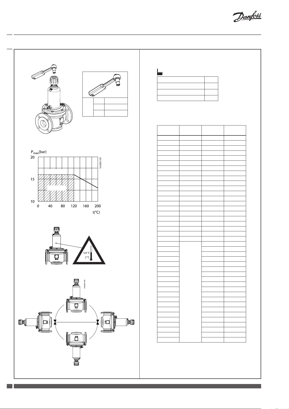
PN 16
workin g area
DN
65 13
80 13
100 13
EN-G JL-250 (GG-25)
❷
①
1)
∆p setting range (bar) bar
0.2 - 0.4 0.30
0.35 - 0.75 0.60
0.6 - 1.0 0.80
②
n (turns)
0 0.40 0.75 1.00
1 0.39 0.74 0.99
2 0.38 0.73 0.98
3 0.37 0.72 0.97
4 0.36 0.71 0.96
5 0.35 0.70 0.95
6 0.34 0.69 0.94
7 0.33 0.68 0.93
8 0.32 0.67 0.92
9 0.31 0.66 0.91
10 0.30 0.65 0.90
11 0.29 0.64 0.89
12 0.28 0.63 0.88
13 0.27 0.62 0.87
14 0.26 0.61 0.86
15 0.25 0.60 0.85
16 0.24 0.59 0.84
17 0.23 0.58 0.83
18 0.22 0.57 0.82
19 0.21 0.56 0.81
20 0.20 0.55 0.80
21 0.54 0.79
22 0.53 0.78
23 0.52 0.77
24 0.51 0.76
25 0.50 0.75
26 0.49 0.74
27 0.48 0.73
28 0.47 0.72
29 0.46 0.71
30 0.45 0.70
31 0.44 0.69
32 0.43 0.68
33 0.42 0.67
34 0.41 0.66
35 0.40 0.65
36 0.39 0.64
37 0.38 0.63
38 0.37 0.62
39 0.36 0.61
40 0.35 0.60
n = 360
0.2-0.4 0.35- 0.75 0.6-1.0
(bar) (bar) (bar)
O
2
DH-SMT/SI VI.LR.G2.02 Danfoss Heating

Installation Guide AHP (DN 65-100)
❸
A
①
A
A
❹
②
DN
65 290 385 93 68 205 145
80 310 390 100 68 218 160
100 347 446 112 68 248 180
L1 H1 H2 D1 D2 D3
mm
Fittings
Danfoss Heating VI.LR.G2.02 DH-SMT/SI
33

Installation Guide AHP (DN 65-100)
ENGLISH
Safety notes
To avoid injury of persons and damages
to the device, it is absolutely necessary
to carefully read and observe these
instructions.
Necessary assembly, start-up and
maintenance work must only be performed
by qualified and authorized personnel.
Disposal instruction
This product should be
dismantled and its
components sorted, if
possible, in various groups
before recycling or disposal.
Always follow the local disposal
regulations.
Installation ❸
AHP must be installed in the return pipe.
The flow must be in the direction of the
arrow on the valve body -fig ①.
It is recommended to install filter ② in the
system supply pipe. The impulse tube must
be flushed through before being fitted on
the + connection of the AHP controller.
Setting/adjustment ➋
The AHP controllers are sold in different Δp
setting ranges. The controllers are factory–
set to a defined value as described on
Factory presseting table ①. The setting on
AHP can be changed by turning the setting
spindle ❶①. Use the following procedure
to set the desired differential pressure:
- turning the spindle clockwise increases
the setting
- turning it counter clockwise reduces the
setting.
If the setting is not known, turn the spindle
fully clockwise. With this the setting on
AHP is at maximum value within setting
range. Now turn the spindle a number of
times (n) as described in ➋② until the
required differential pressure setting is
obtained.
Note: Do not turn the spindle more than
20/40 turns as it will become disengaged.
Starting
During system start please secure that
there is the same static pressure on both
sides or higher pressure on upper side of
the membrane (+ connection).
Dimensions ❹
AHP controller must in addition be
installed as determined by installation
conditions.
Pressure testing
When pressure testing you must secure
that both sides of the membrane have
the same static pressure. That means the
impulse tube must be connected and any
needle valves must be open. During this
operation (closing or opening the valves)
please make sure that there is never lower
pressure on upper side of the membrane.
If this instructions are ignored, the
diaphragm might be damaged.
73695470/VI.LR.G2.02
Produced by Danfoss A/S © 11/2010
 Loading...