

Page 1
Data sheet
Differential pressure controller with flow limitation and
with integrated control valve (PN 16)
AHPBM-F – flow mounting, fixed setting
Description
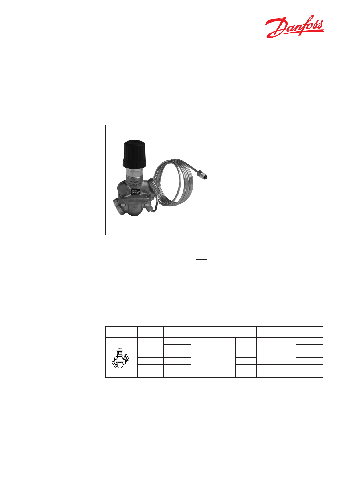
AHPBM-F is a self-acting differential pressure
controller with flow limitation primarily for use in
direct-connected district heating systems with
mixing loop only. The controller closes on rising
differential pressure or when set max. flow is
exceeded.
It can be combined with Danfoss electrical
actuators AMV(E) and controlled by ECL
electronic controllers.
The controller has a control valve with adjustable
flow restrictor, connection neck for electrical
actuator, and an actuator with one control
diaphragm.
Controllers are used together with Danfoss
electrical actuators:
- AMV(E) 10
- AMV(E) 13 with spring return function
- AMV(E) 130, AMV(E) 140
- AMV(E) 130H, AMV(E) 140H with manual
override knob
AHPBM-F combined with AMV(E) 13 has been
approved according to DIN EN 14597.
Main data:
• DN 15-32
• kvs 1.0-6.3 m3/h
• PN 16
• Fixed ∆p setting:
- 0.12 bar for DN 15-20
- 0.14 bar for DN 25-32
• Temperature:
- Circulation water / glycolic water up to 30%:
2 … 120 °C
• Connections:
- Ext. thread (weld-on, thread and flange
tailpieces)
Ordering
Example:
Differential pressure controller
with flow limitation (fixed setting)
and integrated control valve,
DN 15, kVS 1.6, PN 16, flow restrictor
Δp 0.12 bar, t
- 1× AHPBM-F DN 15 controller
Code No.: 003L3582
Option:
- 1× Impulse tube set AH, 1.5 m
Code No: 003L8152
- 1× Fitting for imp. tube
Code No: 003L5042
- 1× Weld-on tailpieces
Code No.: 003H6908
External impulse tube (AH), nipple
for impulse tube and electrical
actuators AMV(E) must be ordered
separately.
DH-SMT/SI
120 °C, ext. thread
max
AHPBM-F Controller
Picture
VD.LR. K1.02 © Danfoss 03/2011
DN
(mm)
15
20 2.5 G 1 A 003L3583
25 4.0 G 1¼ A
32 6.3 G 1¾ A 003L3585
k
VS
(m3/h)
1.0
1.25 003L3581
1.6 003L3582
Connection
G ¾ A
Cylin. ext. thread
acc. to ISO 228/1
∆p setting range
(bar)
0.12
0.14
Code No.
003L3580
003L3584
1
Page 2
Data sheet
0.12(0.14)
Diff. press. controller with flow limitation and with integrated control valve AHPBM-F (PN 16)
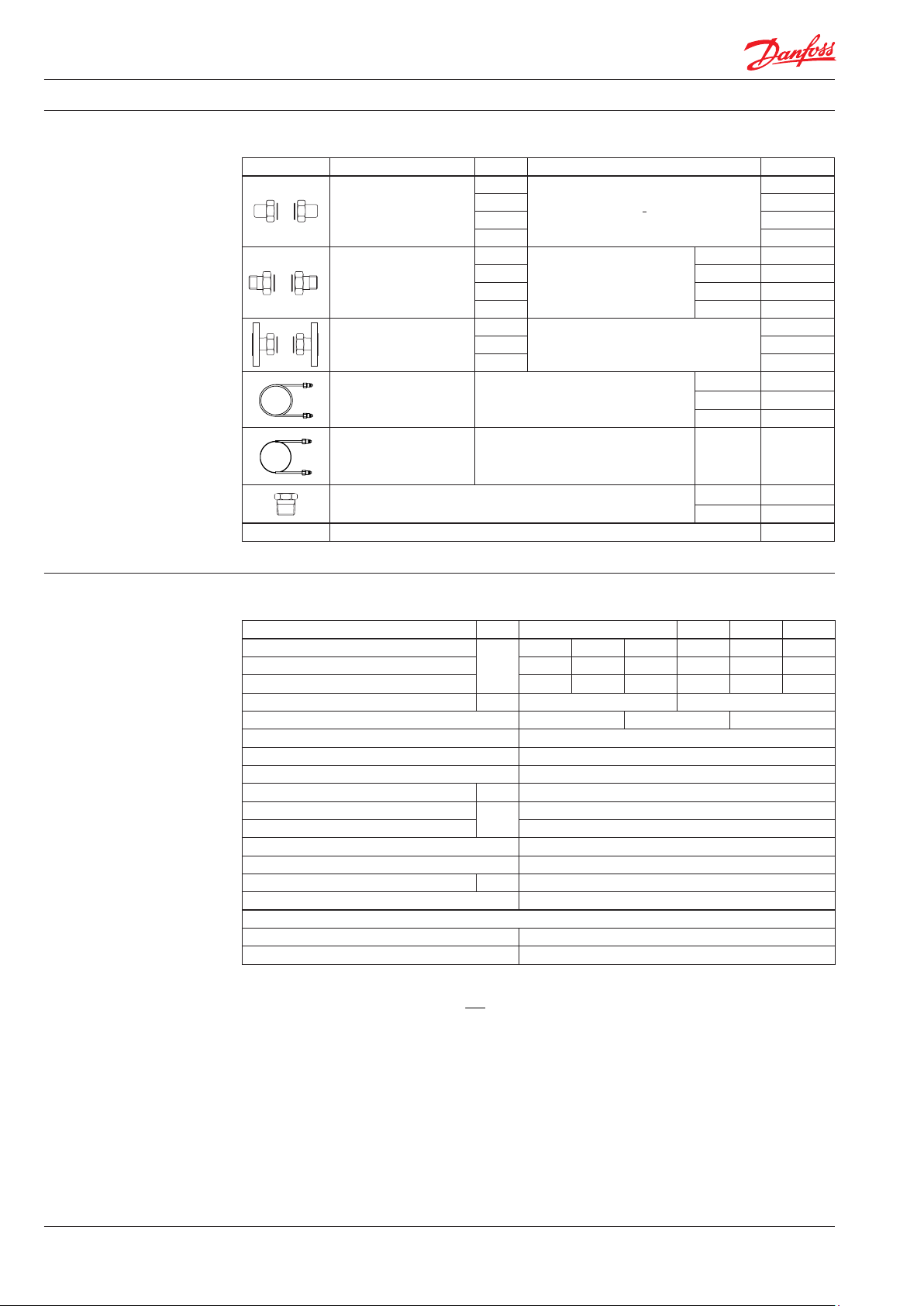
Ordering (continuous)
Accessories
Picture Type designation DN Connection Code No.
15
Weld-on tailpieces
External thread tailpieces
Flange tailpieces
Impulse tube set AH
Impulse tube set AH for
pressure reduction
Fitting for impulse tube connection to pipe
10 EPDM o-rings for impulse tube 003L8175
20 003H6909
25 003H6910
-
32 003H6911
15
20 R ¾ 003H6903
25 R 1 003H6904
Conical ext. thread acc. to
EN 10226-1
R ½ 003H6902
32 R 1¼ 003H6905
15
20 003H6916
Flanges PN 25, acc. to EN 1092-2
25 003H6917
Description:
- 1× copper tube Ø 3 × 1 mm
- 2× fitting for imp. tube connection
to actuator and pipe G /
1.5 m 003L3561
2.5 m 003L5043
5 m 003L3562
Description:
- 1× stainless steel tube Ø 0.8 × 0.2 mm
- 2× fitting for imp. tube connection
0.8 m 003L3560
to actuator and pipe G /
G /-R / 003L5042
G /-R ¼ 003L8151
003H6908
003H6915
Technical data
Valve
Nominal diameter DN 15 20 25 32
k
value
VS
Q
min
Q
* 0.43 0.7 1.0 1.2 2.2 3.4
nom
m3/h
Stroke mm 5.5 5
Control ratio > 1:30 > 1:50 > 1:100
Control characteristic Linear
Cavitation factor z ** ≥ 0.6
Leakage acc. to standard IEC 60534 0.05
Nominal pressure PN 16
Min. differential pressure
Max. differential pressure 4
bar
Medium Circulation water / glycolic water up to 30%
Medium pH Min. 7, max. 10
Medium temperature °C 2 … 120
Connections External thread
Materials
Valve body /valve seat / valve cone Dezincing free brass CuZn36Pb2As
Sealing EPDM
* At differential p ressure across the controller Δp
** kv / kVS ≤ 0.5 at DN 25 and hig her
*** Depe nds on the flow rate and valve k
1)
Depends o n DN
;
Δp +
VS
≥ 0.5 bar
AHPBM-F
2
⎛
⎞
Q
nom
⎜
⎟
=
min
⎜
⎟
k
vs
⎝
⎠
1.0 1.25 1.6 2.5 4.0 6.3
0.035 0.11 0.2 0.25 0.43 0.65
See remark ***
1)
2
VD.LR. K1.02 © Danfoss 03/2011
DH-SMT/SI
Page 3
Data sheet
Diff. press. controller with flow limitation and with integrated control valve AHPBM-F (PN 16)
Technical data (continuous)
Application principles
AHPBM-F controller must be
installed in the flow pipeline
only.
Actuator
Type DN 15 20 25 32
Actuator size cm
Nominal pressure PN 16
Flow restrictor differential pressure (AHQM)
Fixed differential pressure setting (AHPBM-F)
Materials
Housing*
Diaphragm EPDM
Impulse tube
* Actuator ho using is part of valve body
Direct-connected district heating system with mixing
loop only
bar
2
8.5 13 20 32
0.12 0.14
Dezincing free brass CuZn36Pb2As
Copper tube Ø 3 × 1 mm
Stainless steel tube Ø 0.8 × 0.2 × 800 mm
Installation positions The controllers can be installed in horizontal
or vertical pipes with (connection neck for)
electrical actuator oriented upwards.
Electrical actuator
Note!
Installation positions for electrical actuator
AMV(E) have to be observed as well. Please see
relevant Data Sheet.
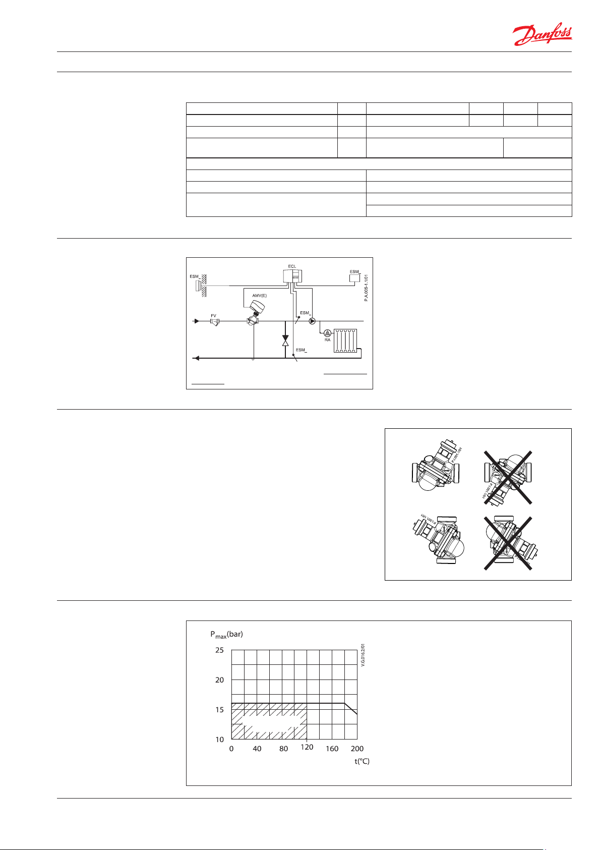
Pressure temperature
diagram
working area
CuZn36Pb2As (DZR) PN 16
DH-SMT/SI
Maximum allowed operating pressure as a function of medium temperature (according to EN 1092-3).
VD.LR. K1.02 © Danfoss 03/2011
3
Page 4

Data sheet
Diff. press. controller with flow limitation and with integrated control valve AHPBM-F (PN 16)
Flow diagram Sizing and setting diagram
Relation between actual flow and number of revolutions on flow restrictor. Values given are
approximate.
DN 32 kVS 6.3
DN 25 kVS 4.0
DN 20 kVS 2.5
DN 15 kVS 1.6
DN 15 kVS 1.25
DN 15 kVS 1.0
Flow can be adjusted by turning flow restrictor screw
counter-clockwise as shown in this diagram
1 = 360º
Water flow shown at differential pressure across the
controller from 0.5 bar (50 kPa) to 4 bar (400 kPa).
4
VD.LR. K1.02 © Danfoss 03/2011
DH-SMT/SI
Page 5

Data sheet
Diff. press. controller with flow limitation and with integrated control valve AHPBM-F (PN 16)
Sizing
- Directly connected heating
system
Example AHPBM-F
(flow mounting only)
Motorised control valve (MCV) for mixing circuit
in direct-connected heating systems requires
differential pressure of 0.12 bar (12 kPa) and flow
less than 600 l/h.
Given data:
Q
= 0.6 m3/h (600 l/h)
max
p
= 0.8 bar (80 kPa)
min
*p
= 0.1 bar (10 kPa)
circuit
p
= 0.12 bar (12 kPa) selected
MCV
* Remark:
p
corresponds to the required pump
circuit
pressure in the heating circuit and is not to be
considered when sizing the AHPBM-F.
The total (available) pressure loss across the
controller is:
p
p
= p
AHPBM-F,A
= 0.8 bar (80 kPa)
AHPBM-F,A
min
Possible pipe pressure losses in tubes, shut-off
fittings, heatmeters, etc. are not included.
Select controller from flow diagram, page 5,
with the smallest possible kVS value considering
available flow ranges.
kVS = 1.6 m3/h
The min. required differential pressure across
the selected controller is calculated from the
formula:
2
Q
max
p
p
p
AHPBM-F,MI N
p
AHPBM-F,A
MINF,-AHPBM
k
VS
2
0.6
MINF,-AHPBM
1.6
0.12
= 0.26 bar (26 kPa)
> p
AHPBM-F,MI N
p
MCV
0.8 bar > 0.26 bar
Solution:
The example selects AHPBM-F DN 15, kVS value
1.6, flow setting range 0.06-0.79 m3/h.
DH-SMT/SI
VD.LR. K1.02 © Danfoss 03/2011
5
Page 6

Data sheet
Design
1. Valve body
2. Control valve insert
3. Adjustable flow restrictor
4. Control valve stem
5. Differential pressure actuator
6. Control diaphragm
7. Built-in spring for flow rate
control
8. Pressure relieved valve cone
9. Impulse tube
Diff. press. controller with flow limitation and with integrated control valve AHPBM-F (PN 16)
Function Pressure changes from the flow and return
pipeline are being transferred through the
impulse tube and control drain to the actuator
chambers and act on control diaphragm. Control
valve closes on rising differential pressure and
opens on falling differential pressure to maintain
constant differential pressure. Flow volume is
controlled and limited by means of the flow
restrictor.
Additionally the electrical actuator will operate
from zero to set max. flow according to the load.
Settings
Flow setting
Flow setting is being done by the adjustment of
the flow restrictor position. The adjustment can
be performed on the basis of flow adjustment
diagram (see relevant instructions) and/or by the
means of heat meter.
6
VD.LR. K1.02 © Danfoss 03/2011
DH-SMT/SI
Page 7

Data sheet
Dimensions
Diff. press. controller with flow limitation and with integrated control valve AHPBM-F (PN 16)
DN 15 20 25 32
L
H 24 31 39 49
H
1
D (ISO 228/1) G ¾A G 1A G 1¼A G 1¾A
Valve weight kg 0.51 0.67 1.47 2.23
65 82 104 130
mm
57 59 72 84
DN 15 20 25 32
SW
32 (G ¾A) 41 (G 1A) 50 (G 1¼A) 63 (G 1¾A)
d 21 26 33 42
1)
R
2)
L1
L2 131 144 160 177
mm
½ ¾ 1 1 ¼
130 150 160 -
L3 139 154 159 184
k 65 75 85 -
d
2
n 4 4 4 -
1)
Conical ex t. thread acc. to EN 10226-1
2)
Flanges PN 25, acc. to EN 1092-2
14 14 14 -
Fittings
DH-SMT/SI
VD.LR. K1.02 © Danfoss 03/2011
7
Page 8

Data sheet
Dimensions (continuous)
Diff. press. controller with flow limitation and with integrated control valve AHPBM-F (PN 16)
AMV(E) 10 + AHPBM-F
DN 15 20 25 32
AMV(E) 10
L*
AMV(E) 13 147 147 164 183
AMV(E) 10 178 186 204 224
L**
AMV(E) 13 188 196 214 234
AMV(E) 10 195 201 223 245
H*
AMV(E) 13 210 216 238 260
AMV(E) 10 174 184 202 222
H**
AMV(E) 13 180 190 208 228
137 137 153 172
mm
AMV(E) 13 + AHPBM-F
AMV(E) 130(H)/140(H) + AHPBM-F
DN 15 20 25 32
L*
L** 148 156 174 194
H* 168 178 196 216
H** 152 162 180 200
8
VD.LR. K1.02
118 125 141 160
mm
Produce d by Danfoss A/S © 03/2011
 Loading...