

Instructions
www.danfoss.de
www.danfoss.de
www.danfoss.de
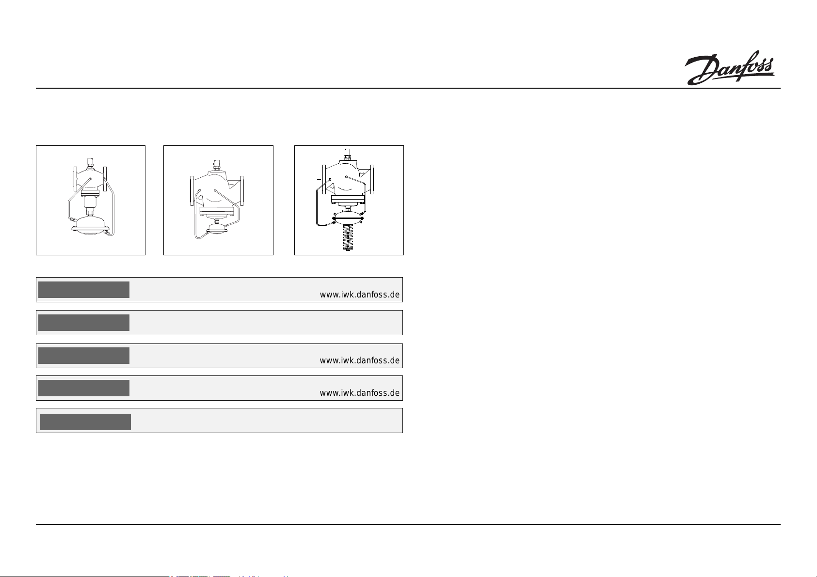
DN 15 - 125 DN 150 - 250 DN 200 - 250
Type AFQ / VFQ 2 DN 15 - 250
ENGLISH
POLSKI
DEUTSCH
РУССКИЙ
FRANCAIS
FRANCAIS
73696470- 06 / 01 VI.DA.D1.5V
Flow controller AFQ VFQ 2
Regulator przep³ywu AFQ / VFQ 2 Spis treci Strona 2
Volumenstromregler AFQ / VFQ 2 Inhalt Seite 2
Регулятор расхода AFQ VFQ 2,
Régulateur de débit volumétrique
AFQ / VFQ 2
Content Page 2
www.iwk.danfoss.de
www.danfoss.pl
www.iwk.danfoss.de
Содержание, стр. 2
www.iwk.danfoss.de
Sommaire Page 2
www.danfoss.fr
1

Type AFQ / VFQ 2
ENGLISH
Contents
Safety Notes 3
Scope of Delivery 4
Assembly 5
– Permissible
Installation Positions 5
– Installation Location,
Installation Scheme 5
– Valve Installation 6
– Assembly of Valve
and Actuator 7
– Control Line
Assembly 8
– Insulation 10
– Dimensions/
Weights 10
Demontage 9
Leak and
Pressure Tests 11
Filling the Systems,
Operational shutdown 11
Setting of Flow
Rate-Limitation 12
– Adjustment via Flow
Adjusting Curves 12
– Flow Adjusting
Curves
Setting Range 14
– Adjust via
Heatmeter 15
– What to do when
the flow rate is low? 16
POLSKI
Spis treci
Warunki bezpieczeñstwa3
Zakres dostawy 4
Monta¿ 5
- Dopuszczalne pozycje
monta¿u 5
- Miejsce i schemat
monta¿u 5
- Monta¿ zaworu 6
- Monta¿ napêdu 7
- Pod³¹czenie przewodów
impulsowych 8
- Izolacja 10
- Wymiary / Wagi 10
Demonta¿ 9
Próba cinieniowa i
szczelnoci 11
Nape³nianie uk³adu.
Zatrzymanie uk³adu 11
Nastawa ograniczenia
przep³ywu 12
- Nastawa na podstawie
krzywych
regulacji przep³ywu 12
- Krzywe regulacji
przep³ywu,
zakresy nastaw 14
- Nastawa na podstawie
wskazañ
ciep³omierza 15
- Co zrobiæ gdy wielkoæ
przep³ywu
jest zbyt ma³a? 16
DEUTSCH
Inhalt
Sicherheitshinweise 3
Lieferumfang 4
Montage 5
– Zulässige
Einbaulagen 5
– Einbauort,
Einbauschema 5
– Einbau Ventil 6
– Montage Ventil
Antrieb 7
– Montage
Steuerleitungen 8
– Isolierung 10
– Abmessungen/
Gewichte 1 0
Demontage 9
Dichtheits-,
Druckprüfung 11
Füllung der Anlage,
Außerbetriebnahme 11
Einstellung Volumen-
strombegrenzung 12
– Einstellung mit
Einstelldiagramm 1 2
– Einstelldiagramme,
Einstellbereiche 14
– Einstellung mit
Wärmezähler 15
– Volumenstrom zu
niedrig, was tun? 16
РУССКИ
Содержание:
Правила техники
безопасности 3
Комплектация 4
Монтаж 5
- Допустимые положения
регулятора при монтаже
5
- Размещение егулятора
(схема установки) 5
- Монтаж клапана 6
- Монтаж клапана и 7
регулирующего элемента
- Подключение линии
управления к клапану 8
- Теплоизоляция 10
- Габаритные и
присоединительные
размеры 10
Демонтаж клапана и
регулирующего
элемента 9
Испытание на прочность
и герметичность 11
Заполнение системы,
рабочее отключение 11
Установка ограничения
расхода 12
- Настройка с помощью
графиков расхода 12
- Графики настройки
расхода, диапазон
регулируемого расхода14
- Настройка с помощью
теплосчетчика 15
- Что делать, если расход
меньше расчетного 16
FRANCAIS
Sommaire
Consignes de sécurité 3
Contenu de la livraison 4
Montage 5
- Orientations de
montage autorisées 5
- Lieu de montage,
schéma de montage 5
- Montage vanne 6
- Montage vanne,
moteur 7
- Montage conduites
de commande 8
- Isolation 10
- Dimensions / poids 10
Démontage 9
Contrôle d’étanchéité et
de pression 11
Remplissage de
l’installation, mise hors
service 11
Réglage de la limitation
du débit 12
- Réglage avec
diagramme de réglage12
- Diagrammes de
réglage, plages de
réglage 14
- Réglage avec compteur
thermique 1 5
- Débit trop faible, que
faire ? 16
2
Type AFQ / VFQ 2
ENGLISH
Safety Notes
To avoid injury of persons
and damages to the
device, it is absolutely
necessary to carefully read
and observe these instructions.
Necessary assembly, star tup, and maintenance may
be performed only by
qualified and authorized
personnel.
It is absolutely necessary to
depressurize system prior
to any work.
Please comply with the
instructions of the system
manufacturer or system
operator.
Definition of Application
The flow rate controller is
used for flow rate restriction
of water and water-glycolmixtures in heating, district
heating and cooling
systems.
The application must be
limited to the rated conditions as stated on the rating
plates that are mounted to
each device.
POLSKI
Warunki bezpieczeñstwa
W celu unikniêcia ryzyka
zranienia osób i
uszkodzenia urz¹dzeñ
nale¿y bezwzglêdnie i
wnikliwie zapoznaæ siê z
niniejsz¹ instrukcj¹.
Niezbêdny monta¿,
uruchomienie oraz
obs³uga mog¹ byæ
dokonywane wy³¹cznie
przez wykwalifikowany i
autoryzowany personel.
Nale¿y bezwzglêdnie
zrzuciæ cinienie z uk³adu
przed monta¿em i
demonta¿em.
Prosimy stosowaæ siê do
instrukcji producenta i/lub
operatora uk³adu.
Zakres zastosowañ
Regulator przep³ywu
stosowany jest do
ograniczania przep³ywu dla
wody i roztworu woda-glikol
w uk³adach grzewczych,
instalacjach sieci cieplnych
i ch³odzenia.
Zastosowanie ograniczone
jest do zakresu
parametrów okrelonych
na tabliczce znamionowej
umieszczonej na ka¿dym z
urz¹dzeñ.
DEUTSCH
Sicherheitshinweise
Um Verletzungen an Perso-
nen und Schäden am Gerät
zu vermeiden, diese Anlei-
tung unbedingt beachten.
Montage, Inbetriebnahme
und Wartungsarbeiten
dürfen nur von sachkundigen und autorisierten
Personen durchgeführt
werden.
Anlage vor Montage,
Demontage unbedingt
drucklos machen.
Die Vorgaben des Anlagenherstellers und Anlagenbetreibers sind zu
beachten.
Bestimmungsgemäße
Verwendung
Der Volumenstromregler
dient der Volumenstrombegrenzung von Wasser
und Wasser-Glykolgemischen für Heizungs-,
Fernheizungs- und
Kühlungsanlagen.
Die technischen Daten auf
den Typenschildern sind für
den Einsatz maßgebend.
РУССКИЙ
Правила техники
безопасности
Для предупреждения
травматизма персонала
и повреждения
оборудования
необходимо
внимательно прочитать и
соблюдать настоящую
инструкцию.
Монтажные работы, ввод
в эксплуатацию
оборудования и
обслуживание может
производить только
квалифицированный
персонал, имеющий
допуск к таким работам.
Перед началом работ по
монтажу или демонтажу
регулятора необходимо
сбросить давление в
трубопроводной системе.
Соблюдайте также
инструкции по
эксплуатации системы.
Область применения
Регулятор расхода
предназначен для
ограничения расхода
воды и водных смесей
гликоля в системах
централизованного
теплоснабжения и
охлаждения.
Границы применимости
определяют технические
характеристики на
фирменной табличке
регулятора
FRANCAIS
Consignes de sécurité
Pour éviter les risques de
blessure pour les personnes
et les dommages sur
l’appareil, lire attentivement
cette notice.
Le montage, la mise en route
et les travaux d’entretien
doivent être effectués par du
personnel qualifié et
autorisé.
Mettre impérativement
l’installation hors pression
avant tout montage ou
démontage.
Respecter les consignes du
fabricant de l’installation et
de l’exploitant de celle-ci.
Conditions d’utilisation
Le régulateur de débit
volumétrique est approprié
pour la limitation du débit de
l’eau et de l’eau glycolée
pour chauffage, chauffage
urbain et installations de
réfrigération.
Les données techniques sur
les plaques signalétiques
sont déterminantes pour
l’utilisation.
3
Type AFQ / VFQ
ENGLISH
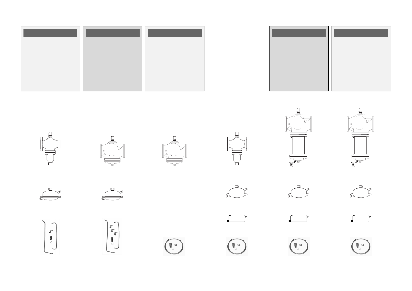
Scope of Delivery
DN 15 - 125
t
= 150 °C
max
VFQ 2 DN 15 - 125
POLSKI
Zakres dostawy
DN 150 - 250
t
= 140 °C
max
VFQ 2 DN 150 - 250
DEUTSCH
Lieferumfang
DN 200 - 250
t
= 140 °C
max
VFQ 2 DN 200 - 250
DN 15 - 25
t
= 200 °C
max
VFQ 2 DN 15 - 125
РУССКИЙ
Комплектация
DN 150 + 250
t
= 200 °C
max
VFQ 2 DN 150 + 250
FRANCAIS
Contenu de la
livraison
DN 200 + 250
t
= 200 °C
max
VFQ 2 DN 200 + 250
AFQ
AFQ
AFQ
AFQ
AFQ 2
AF (3x)
AFQ
V1 (2x)
AF (2x)
AFQ
V1 (2x)
AF (3x)
AFQ 2
V2 (2x)
AF (3x)
4
Type AFQ / VFQ 2
ENGLISH POLSKI
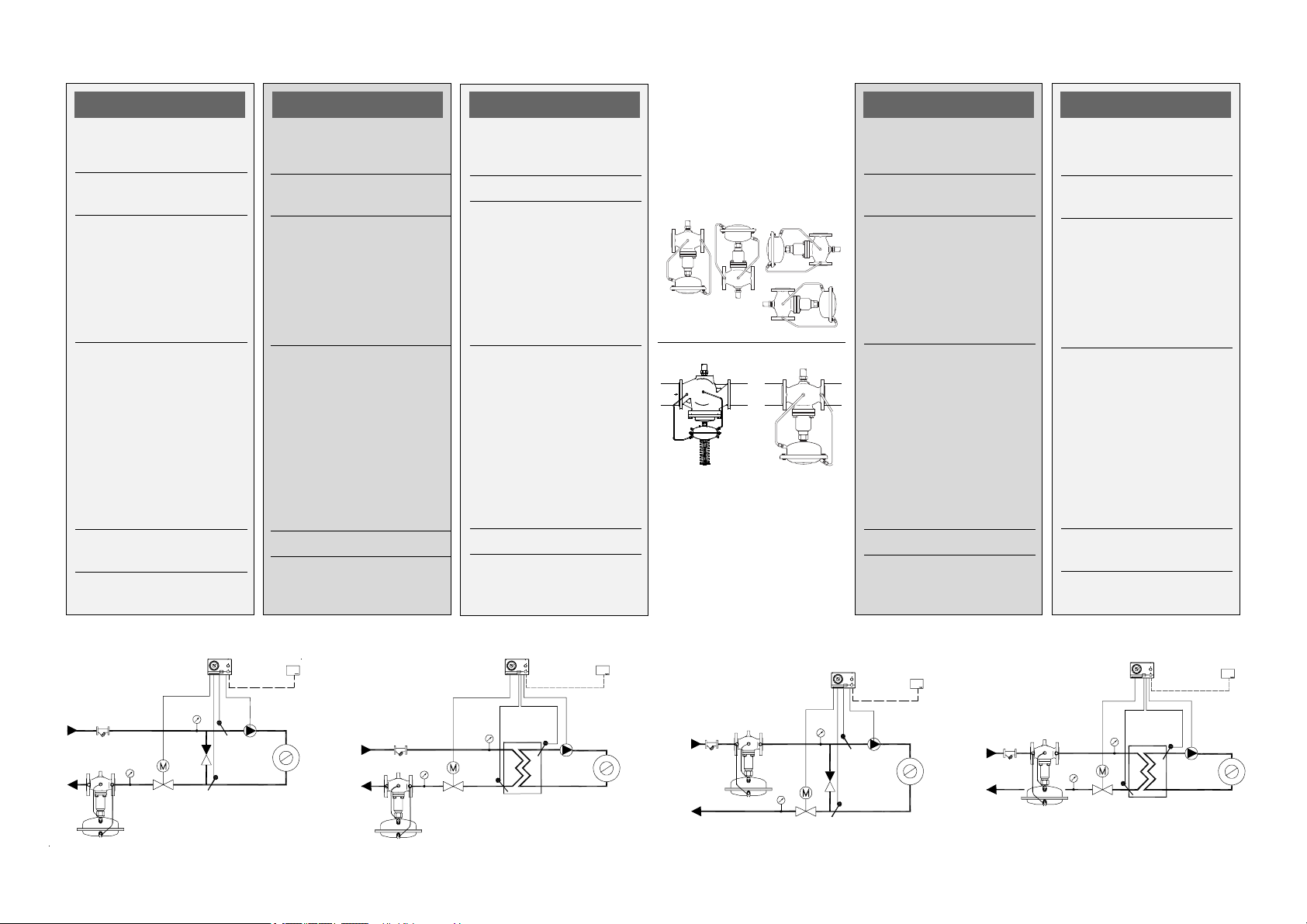
Assembly
Permissible Installation
Positions
DN 15 - 80
Medium temperatures
up to 120 °C
Any installation position
DN 100 – 250
and by DN 15 - 80 when
medium temperature is
above 120 °C.
Installation is permitted
only in horizontal pipelines
with the actuator handing
downwards.
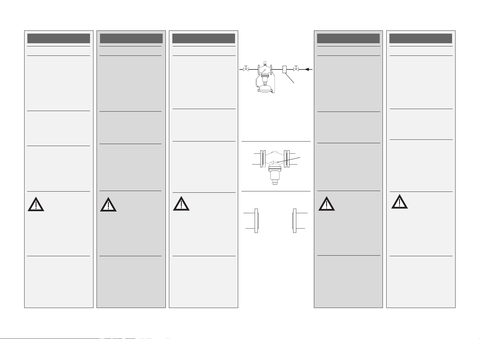
Installation Location,
Installation Scheme
Flow or return pipe
Monta¿
Dopuszczalne pozycje
monta¿u
DN 15 80
Temperatura czynnika do
120
Dowolna pozycja monta¿u
DN 100 250
i DN 15 80 gdy
temperatura czynnika jest
wy¿sza ni¿ 120oC
Monta¿ dozwolony tylko na
ruroci¹gu poziomym z
napêdem skierowanym do
do³u.
Miejsce i schemat monta¿u
Ruroci¹g zasilaj¹cy lub
powrotny.
DEUTSCH
Montage
Zulässige Einbaulagen
DN 15 - 80
Mediumstemperaturen
bis 120 °C:
o
C
Einbaulage beliebig
DN 100 - 250
und bei DN 15 - 80, wenn
die Mediumstemperatur
größer 120 °C.
Einbau nur in waagrechte
Rohrleitung mit nach
unten hängen dem Antrieb
zulässig
Einbauort, Einbauschema
Vorlauf oder Rücklauf
DN 100 - 250
DN 200 + 250
РУССКИЙ
Монтаж
Допустимые положения
регулятора при монтаже
15 80.
Ä
Ó
Температура
перемещаемой среды до
Î
Ñ.
120
Монтаж в любом
положении.
ÄÓ 100 250 è ÄÓ 15 80,
температура
перемещаемой среды
выше 120 ОС. Монтаж
разрешается только на
горизонтальном
трубопроводе
регулирующим
элементом вниз.
Размещение регулятора
(схема установки)
FRANCAIS
Montage
Orientations de montage
autorisées
DN 15 - 80
Température du fluide
jusqu’à 120°C :
Orientation au choix
DN 100 – 250
et pour DN 15-80, si la
température du fluide est
supérieure à 120°C :
Montage autorisé
uniquement sur tuyauterie
horizontale, avec moteur
vers le bas.
Lieu de montage, schéma
de montage
Aller ou retour
5
Type AFQ / VFQ 2
ENGLISH
Valve Installation
1. Install strainer À before
the controller.
2. Prior to installing the
valve, rinse system.
3. Observe flow direction Á on the valve-
body.
The flanges  in the
pipeline must be in parallel
position and the sealing
surfaces must be clean
and without damage.
POLSKI
Monta¿ zaworu
1.Zamontowaæ filtr
przed regulatorem.
2. Przed zamontowaniem
zaworu przep³ukaæ
instalacjê.
3. Zwróciæ uwagê na
wskanik kierunku
przep³ywu Á na korpusie
zaworu.
Ko³nierze na ruroci¹gu Â
musz¹ byæ wzajemnie
równoleg³e, a
powierzchnie pod
uszczelki czyste i bez
uszkodzeñ.
À
DEUTSCH
Einbau Ventil
1. Schmutzfänger
dem Regler einbauen
2. Anlage vor dem Einbau
des Ventils spülen
3. Durchflussrichtung Á
auf dem Ventilgehäuse
beachten
Flansche  in der Rohrleitung müssen parallel,
Dichtflächen sauber und
ohne Beschädigung sein.
À vor
Â
À
Á
РУССКИЙ
Монтаж клапана
1.Перед регулятором
установить сетчатый
фильтр
2. Перед установкой
клапана промыть
систему.
3. Сверить направление
потока и стрелки Á
на корпусе клапана.
установлены
параллельно, а
уплотняемые
поверхности должны
быть чистыми и без
повреждений.
À .
Фланцы Â íà
трубопроводе
должны быть
FRANCAIS
Montage vanne
1. Monter le filtre
le régulateur
2. Rincer l’installation
avant le montage
3. Respecter le sens
d’écoulement
indiqué sur la vanne
Les brides  dans la
tuyauterie doivent être
parallèles, les surfaces
d’étanchéité propres et
sans dommages.
À devant
Á
4.Install valve.
5. Tighten screws
crosswise in 3 steps up
to the maximum torque.
4.Zamontowaæ zawór.
5.Dokrêcaæ przeciwleg³e
nakrêtki w 3 krokach do
osi¹gniêcia
maksymalnego
momentu.
4. Ventil einbauen
5. Schrauben über Kreuz
in 3 Stufen bis zum
max. Drehmoment
anziehen
4. Установить клапан.
5. Крестообразно
затянуть болты в три
этапа до достижения
максимального
крутящего момента.
4. Monter la vanne
5. Serrer les vis en 3
étapes en croix,
jusqu’au couple de
rotation max.
6
Type AFQ / VFQ 2
ENGLISH
Assembly of
Valve and Actuator
Valves DN 150 - 250
For valves
DN 150 – DN 250, the
actuator stem must be
screwed into the stem of
the valve.
Please observe the
Assembly Instructions
enclosed with the valves
DN 150 – DN 250
shipment.
Valves DN 15 - 125
1. Align actuator with the
control line connection
À.
2. Tighten union nut
Torque: 100 Nm
Á
POLSKI
Po³¹czenie zaworu z
napêdem
Zawory DN 150 250
W zaworach DN 150 250
trzpieñ napêdu musi
zostaæ wkrêcony w trzpieñ
zaworu.
Szczegó³y mo¿na znaleæ
w Instrukcji Monta¿u
zaworów DN 150 250.
Zawory DN 15 125
1. Ustawiæ napêd
pamiêtaj¹c o pozycji
przy³¹cza przewodu
impulsowego
2. Dokrêciæ nakrêtkê
³¹cz¹c¹ Á. Moment: 100
Nm
À
DEUTSCH
Montage
Ventil Antrieb
Ventile DN 150 - 250
Bei den Ventilen
DN 150 - 250 muss die
Antriebstange in die Ventilstange eingeschraubt
werden.
Den Ventilen DN 150 - 250
beigefügte Montageanleitung beachten.
Ventile DN 15 - 125
1. Antrieb wegen dem
Steuerleitungsanschluss
2. Überwurfmutter
anziehen
Anzugsmoment 100 Nm
À ausrichten
Á
100 Nm
Á
46 mm
DN 150 - 250
РУССКИЙ
Монтаж
регулирующего
элемента
Клапаны ДУ 150 250
Для клапанов ДУ 150
250 шток регулирующего
элемента должен быть
завинчен в шток клапана.
Одновременно обратите
внимание на инструкцию
по монтажу,
прилагаемую к партии
клапанов Д
Клапаны ДУ 15 125
1.Повернуть
À
регулирующий элемент
до требуемого
положения штуцера
для импульсной трубки.
2.Затянуть
соединительную гайку
Á крутящим
моментом 100 Нм.
150 250.
Ó
FRANCAIS
Montage vanne,
moteur
Vannes DN 150 - 250
Pour les vannes DN 150 250, la tige du moteur doit
être vissée dans la tige de
la vanne.
Respecter la notice de
montage jointe, pour les
vannes DN 150 – 250.
Vannes DN 15 –125
1. Aligner le moteur avec le
raccordement de
conduite de commande
À
À
2. Serrer l’écrou prisonnier
Á, facteur de serrage
100 Nm
7

Type AFQ / VFQ 2
ENGLISCH
Impulse Tube Assembly
Note
If control lines (copper) are
not pre-bent or seal pots
are to be installed, please
observe the Assembly
Instructions of these parts.
Control Line Assembly
(stainless steel) À
1. Remove plugÁ at the
valve.
2. Screw in a threaded
joint
 with a copper
gasket Ã.
Torque: 40 Nm
3.Verify that the cutting
ring
Ä position is
correct.
POLSKI
Pod³¹czenie rurek
impulsowych
Uwaga
Jeli rurki impulsowe
(mied) nie s¹ wstêpnie
wygiête lub musz¹ byæ
zainstalowane naczynia
kondensacyjne, szczegó³y
monta¿u znaleæ mo¿na w
Instrukcjach Monta¿u tych
czêci.
Pod³¹czenie przewodów
impulsowych (stal
nierdzewna) À
1.Usun¹æ zalepkê Á z
zaworu.
2. Wkrêciæ gwintowany
³¹cznik
uszczelk¹ Ã.
3. Sprawdziæ, czy po³o¿enie
piercieni zaciskowych Ä
jest prawid³owe.
 z miedzian¹
DEUTSCH
Montage Steuerleitungen
Hinweis
Bei nicht vorgebogenen
Steuerleitungen (Kupfer)
und bei Einbau von
Vorlagegefäßen, bitte
diesen Teilen beigefügte
Montageanleitung
beachten.
Montage Steuerleitungen
(Edelstahl) À
1.Stopfen Áam Ventil
entfernen
2. Verschraubung
KupferdichtungÃeinschrauben,
Anzugsmoment 40 Nm
3. Richtige Lage des
Schneidrings
prüfen
 mit
Ä über-
Á
Ã
Â
Ä
À
РУССКИЙ
Монтаж импульсных
трубок
Примечание
Перед установкой
уплотнительных
элементов на еще не
изогнутые медные
импульсные трубки
следует изучить
инструкции по их
монтажу.
Подключение линии
управления
(нержавеющая сталь)
À к клапану
1.Снять заглушку
корпусе клапан.
2.Завинтить в резьбовое
отверстие
медной прокладкойÃ.
Крутящий момент 40
Íì.
3.Проверить, чтобы была
правильно установлена
разрезная шайба
Á íà
 штуцер с
Ä.
FRANCAIS
Montage conduites de
commande
Indication
Si les conduites de
commande (cuivre) ne
sont pas pré-courbées, ou
avec montage de pots de
condensation, respecter la
notice de montage jointe à
ces pièces.
Montage conduites de
commande (acier inox) À
1. Enlever les bouchons Á
sur le corps de la vanne
2. Visser le raccord
un joint cuivre à dans le
filetage, facteur de
serrage 40 Nm
3. Vérifier la bonne position
du raccord à olive
 avec
Ä
4. Screws angle to the
pressure actuator.
DN 15 - 125
DN 150 - 250 Å + Æ
Å
4. Wkrêciæ z³¹czkê k¹tow¹
Å do napêdu.
4. Winkel am Druckantrieb anschrauben.
DN 15 - 125 Å
DN 150 - 250 Å + Æ
Æ
Å
4.Завинтить уголок 6 в
регулирующий элемент.
DN 15 - 125
DN 150 - 250Å + Æ
Å
4. Visser les coudes Å sur
le moteur
DN 15 – 125
DN 150 - 250 Å + Æ
Å
8

Type AFQ / VFQ 2
ENGLISH
5. DN 150 - 250, screws
angle À to the valve
6. Press control line Á
into the threaded joint
as far as it goes.
7. Tighten union nut
Torque: 40 Nm
Â
Disassembly of
Valve, Actuator
Danger
Danger of injury by steam
or hot water!
Valve without actuator is
À, sealing Á is in
open
the actuator.
It is absolutely necessary
to depressurize system
prior to any work.
Carry out disassembly in
reverse order as
assembly.
POLSKI
5. DN 150 250, wkrêciæ
z³¹czkê k¹tow¹ À do
zaworu.
6. Wcisn¹æ przewód
impulsowy
gwintowany najg³êbiej
jak mo¿na.
7. Dokrêciæ nakrêtkê
³¹cz¹c¹
Nm
Á w ³¹cznik
Â. Moment: 40
Demonta¿ zaworu,
napêdu
Uwaga
Ryzyko poparzenia
par¹ lub gor¹c¹ wod¹!
Zawór bez napêdu jest
otwarty À, uszczelnienie
Á znajduje siê w
napêdzie.
Przed demonta¿em nale¿y
bezwzglêdnie zrzuciæ
cinienie z uk³adu.
Kolejnoæ wykonywanych
czynnoci przy demonta¿u
odwrotna w stosunku do
kolejnoci podczas
monta¿u.
DEUTSCH
5. DN 150 - 250 Winkel À
am Ventil anschrauben
6. Steuerleitung Á in die
Verschraubung bis zum
Anschlag drücken
7. Überwurfmutter
anziehen,
Anzugsmoment 40 Nm
Â
Demontage
Gefahr
Verletzungsgefahr durch
Heißwasser
Ventil ist ohne Antrieb
À, Abdichtung Á
offen
befindet sich im Antrieb.
Vor Demontage Anlage
unbedingt drucklos
machen.
Demontage in umgekehrter Reihenfolge wie die
Montage durchführen.
Á
À
Â
Á
À
РУССКИЙ
5. ДУ 150 250, завернуть
уголок À в корпус
клапана.
6.Вдвинуть трубку
управления Б в
резьбовое соединение
до упора.
7.Затянуть
соединительную гайку
В крутящим моментом
40 Íì.
Демонтаж клапана,
регулирующего
элемента
Внимание!
Будьте осторожны!
Существует опасность
обжечься горячей
водой.
Клапан без
регулирующего элемента
открыт для выхода воды
À. Уплотнение
находится в
регулирующем элементе
Á .
Поэтому до проведения
любых работ необходимо
сбросить давление в
системе!
Демонтаж выполняется в
обратном порядке по
отношению к монтажу.
FRANCAIS
5. DN 150 – 250 Visser le
coude À sur la vanne
6. Pousser la conduite de
commande Á dans le
filetage jusqu’en butée.
7. Serrer l’écrou
prisonnier
serrage 40 Nm
Â, facteur de
Démontage
Danger
Risques de brûlures par
l’eau chaude
La vanne n’est pas
étanche sans moteur
le cône d’étanchéité Á se
trouve dans l’écrou de
fixation du moteur.
Impérativement mettre
l’installation hors
pression avant tout
démontage.
Pour le démontage suivre
la procédure de montage
dans le sens inverse.
À,
9

Type AFQ VFQ 2
ENGLISH
Insulation
For medium temperatures
up to 100 °C the pressure
actuator
insulated, too.
Dimensions, Weights
Flanges – connection
dimensions acc. too
DIN 2501, seal form C
À may be
POLSKI
Izolacja
Dla temperatur czynnika do
o
100
C napêd cinieniowy
À mo¿e zostaæ zaizolowany.
Wymiary, wagi
Ko³nierze wymiary
po³¹czeñ zgodne z DIN
2501, uszczelka typu C
DEUTSCH
Isolierung
Bei Mediumstemperaturen
bis 100 °C kann auch der
Druckantrieb
werden.
Abmessungen, Gewichte
Flansche Anschlussmaße
nach DIN 2501,
Dichtleiste Form C
À isoliert
VFQ 2 DN 15 20 25 32 40 50 65 80 100 125 150 200 250
L 130 150 160 180 200 230 290 310 350 400 480 600 730
B
mm
212 212 238 238 240 240 275 275 380 380 326 354 404
kg 7 9 10 13 17 22 33 41 60 79 85 145 228
B1 mm––––––––––6308551205
kg 140 210 300
À
À
РУССКИЙ
Теплоизоляция
При температурах
перемещаемой среды до
100 ОС регулирующий
элемент А может быть
также изолирован.
Габаритные и присое-
динительные размеры
Фланцы присоед-
инительные размеры в
соответствии с DIN 2501,
форма уплотнения С.
FRANCAIS
Isolation
Avec des températures de
fluide jusqu’à 100°C, le
moteur
être isolé.
Dimensions, poids
Dimensions
raccordement à brides
selon DIN 2501,
étanchéité forme C
À peut également
AFQ AFQ AFQ2
A 263 380
H
B
mm
150 580
L
L
B
VFQ 2 DN 15 - 125 VFQ 2 DN 150 - 250
L
1
B
VFQ 2 DN 150 - 250
t
200 °C
max
A
A
H
H
AFQ (9 kg) AFQ2 (28 kg)
10
Type AFQ / VFQ 2
ENGLISH
Leak and
Pressure Tests
The max. opera-
ting pressure of
25 bar must not
be exceeded when the
control line is installed.
Non-compliance may
cause actuator leakage.
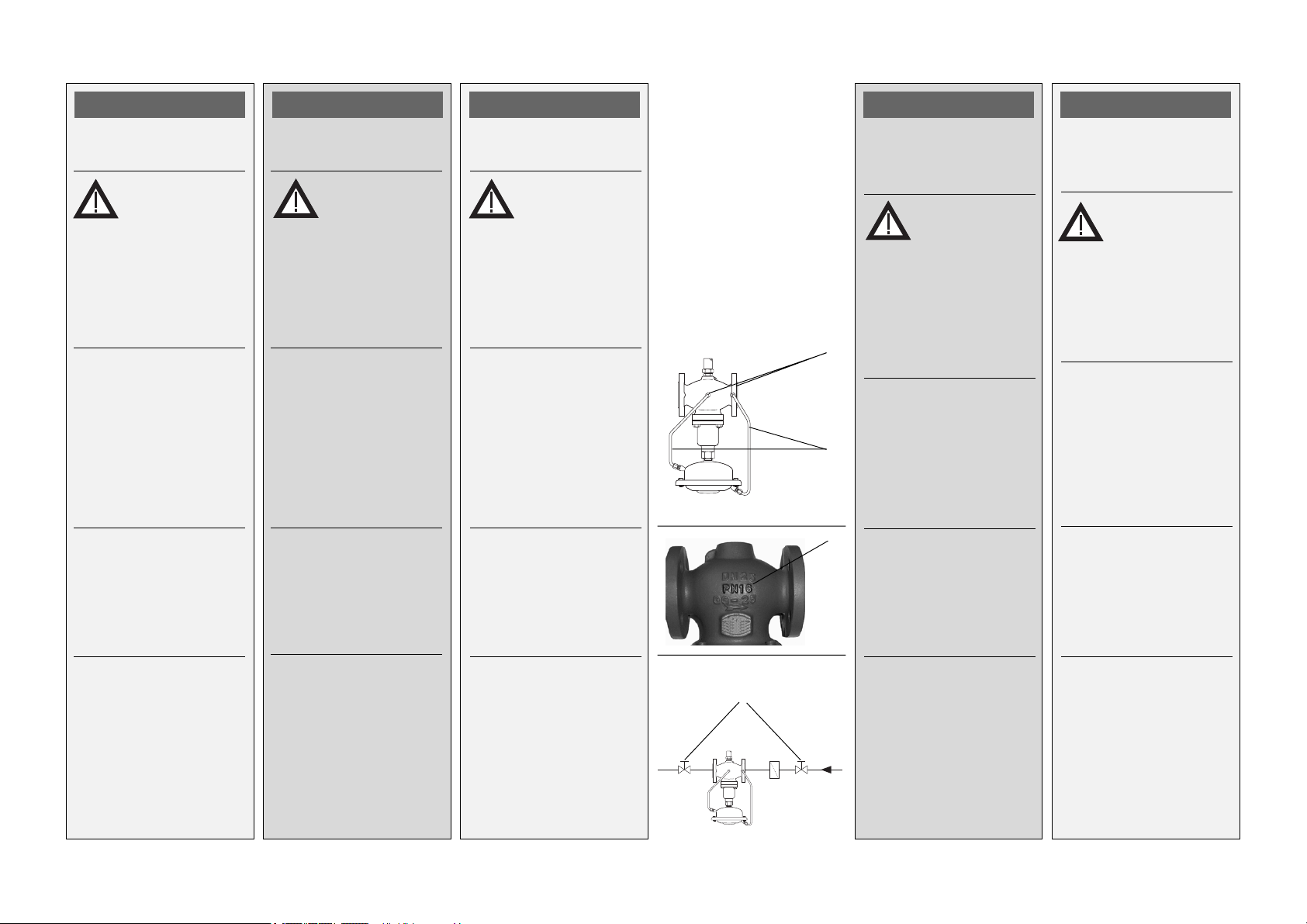
For higher test pressures,
remove impulse tubes À
from the valve.
Close the connections at
the valve with plugs G ¼
ISO 228 Á.
Observe the nominal
pressure  of the valve.
The maximum test
pressure is 1.5 x PN
Filling the System
Slowly open shut-off
units Ã.
Operational
shutdown
Slowly close the shut-off
units Ã.
POLSKI
Próba cinieniowa i
szczelnoci
Nie wolno
przekroczyæ max.
cinienia
roboczego 25 bar jeli
pod³¹czone s¹ przewody
impulsowe.
Nieprzestrzeganie
powy¿szego mo¿e
spowodowaæ przecieki w
napêdzie.
Dla wy¿szych cinieñ
próbnych, od³¹czyæ
przewody impulsowe À
od zaworu.
Otwory w zaworze
zakorkowaæ zaœlepkami z
gwintem G ¼ wg ISO 228
Á..
Sprawdziæ wartoæ
cinienia nominalnego Â
na korpusie zaworu.
Max cinienie próbne
wynosi 1,5 x PN
Nape³nianie uk³adu
Powoli otworzyæ zawory
odcinaj¹ce Ã.
Zatrzymanie uk³adu
Powoli zamkn¹æ zawory
odcinaj¹ce Ã.
DEUTSCH
Dichtheits-,
Druckprüfung
Mit eingebauter
Steuerleitung darf
der max. Be-
triebsbsdruck von 25 bar
nicht überschritten werden.
Nichtbeachtung kann zu
Undichtheit am Antrieb
führen.
Bei höheren Prüfdrücken
müssen die Steuerleitungen À am Ventil entfer nt
werden.
Die Anschlüsse am Ventil
mit Stopfen G ¼ ISO 228
Á. schließen
Nenndruck  des Ventils
beachten.
Max. Prüfdruck ist
1,5 x PN
Füllung der Anlage
Absperrarmaturen Ã
lang-sam öffnen
Außerbetriebnahme
Absperrarmaturen Ã
langsam schließen
Ã
РУССКИЙ
Испытания на
прочность и
герметичность
Åñëè
установлена
трубка
управления, то íå
следует превышать
рабочее давление 25
áàð. Несоблюдение этого
требования может стать
причиной разрыва
диафрагмы
Á
регулирующего элемента.
При высоких давлениях
опрессовки необходимо
снять с клапана
импульсные трубки
À
Заглушить
присоединительные
отверстия заглушками
с резьбой G¼ ISO 228
Â
Прочтите значение
условного давления
на корпусе клапана.
Максимальное
испытательное
давление определяется
êàê 1,5 õ Ð
Заполнение системы
Медленно открыть
запорные устройства Ã .
Рабочее отключение
системы
Медленно закрыть
рабочие устройства
Ó
À .
Â
à .
FRANCAIS
Contrôle
d’étanchéité et de
pression
Avec la conduite
de commande
montée, la
pression de service max.
de 25 bar ne doit pas être
dépassée. En cas de nonrespect, une fuite peut
survenir sur le moteur.
Avec des pressions de
contrôle plus élevées, les
conduites de commande
À doivent être retièes de
la vanne.
Fermer les raccordements
sur la vanne avec des
bouchons G ¼ ISO 228
Á
Á.
Respecter la pression
nominale  de la vanne.
La pression de contrôle
max. est 1,5 x PN
Remplissage de
l’installation
Ouvrir lentement les
robinets d’arrêt Ã.
Mise hors service
Fermer lentement les
robinets d’arrêt Ã.
11

Type AFQ / VFQ 2
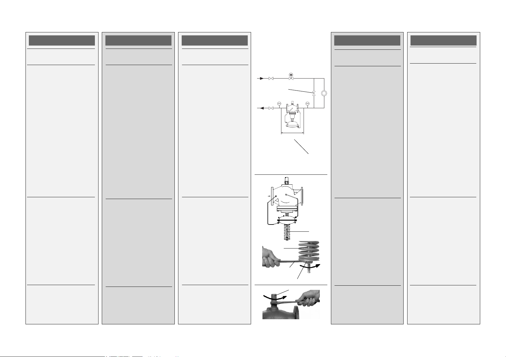
ENGLISH
Setting of Flow
RateLimitation
The flow rate is adjusted
via the setting of adjusting
throttle stroke À.
There are two possibilities:
1. Adjustment via the flow
adjusting curves,
only DN 15 - 125
2. Adjustment with heat
meter, see page 15.
Adjustment via Flow
Adjusting Curves
The system must not be
in operation!
Under high pressure, the
actuator may be damaged
when the adjusting throttle
is closed (step 3.).
1.Only with external
pressure spring Á:
Completely prestress
pressure spring by
turning the set-point
adjuster  up to its
stop.
2. Unscrew cap nut
loosen counter nut.
Ã,
POLSKI
Nastawa
ograniczenia
przep³ywu
Wielkoæ przep³ywu
zadawana jest przez
odpowiednie ustawienie
po³o¿enia d³awika
nastawczego À.
Istniej¹ dwie metody:
1. Nastawa na podstawie
krzywych regulacji
przep³ywu, tylko dla DN
15 - 150
2. Nastawa na podstawie
wskazañ ciep³omierza.
Nastawa na podstawie
krzywych regulacji
przep³ywu
Uk³ad nie mo¿e
pracowaæ!
Wysokie cinienie mo¿e
uszkodziæ napêd gdy
d³awik nastawczy jest
zamkniêty (krok 3.).
1. Tylko dla napêdów z
zewnêtrzn¹ sprê¿yn¹
regulacyjn¹ Á:
Ca³kowicie cisn¹æ
sprê¿ynê Á przez
dokrêcenie nakrêtki
nastawczej  do koñca.
2. Odkrêciæ os³onê
poluzowaæ
przeciwnakrêtkê.
Ã,
DEUTSCH
Einstellung
Volumenstrombegrenzung
Die Einstellung des Volumenstroms erfolgt über die
Einstellung des Hubes der
Einstelldrossel À.
Es gibt 2 Möglichkeiten:
1. Einstellung mit
Einstelldiagramm,
nur DN 15 - 125
2. Einstellung mit Wärme-
zähler, siehe Seite 15
Einstellung mit
Einstelldiagramm
Die Anlage darf nicht in
Betrieb sein.
Durch schließen der
Einstelldrossel (Schritt 3.)
kann sonst bei hohen
Druckdifferenzen der
Antrieb beschädigt
werden.
1. Nur bei außenliegender Druckfeder
Druckfeder ganz vorspannen, durch Drehung
des Sollwertstellers
Á:
Âbis zum Anschlag
2. Hutmutter
ben, Kontermutter lösen.
à abschrau-
Ã
Á
36 mm
Â
À
РУССКИЙ
Установка
ограничения
расхода
Значение требуемого
расхода настраивается
вращением дрос-
Á:
15
Ó
À.
сельного клапана
Имеется две
возможности:
1.Настройка с помощью
графиков расхода,
(только для Д
150)
2.Настройка с помощью
теплосчетчика, см. стр.
15.
Настройка с помощью
графиков расхода
Система
должна быть
отключена.
Åñëè ïðè
высоком давлении в
системе настроечный
дроссельный клапан
закрыт, то регулируемый
элемент может быть
поврежден (пункт 3)
1.Только с внешней
пружиной регулировки
давления
полностью сжать
рабочую пружину
регулирующего
элемента путем
поворота настроечной
 до упора.
гайки
2.Отвернуть крышку Ã è
ослабить контргайку.
FRANCAIS
Réglage de la
limitation du débit
Le réglage du débit
s’effectue par le réglage
de la course du limiteur
À.
Il y a 2 possibilités :
1. Réglage avec
diagramme de réglage
(uniquement DN 15 –
125)
2. Réglage avec
compteur thermique,
voir page 15
Réglage avec
diagramme de réglage
L’installation ne
doit pas être en
service.
Sinon, la fermeture du
limiteur (phase 3) peut
occasionner des dégâts
sur le moteur, lors de
différences de pressions
élevées.
1. Uniquement avec
ressort de rappel
extérieur: Tendre
totalement le ressort,
en tournant le régleur
de valeur de consigne
Á
 jusqu’en butée.
2. Dévisser l’écrou du
capot, desserrer le
contre-écrou.
12

Type AFQ / VFQ 2
ENGLISH
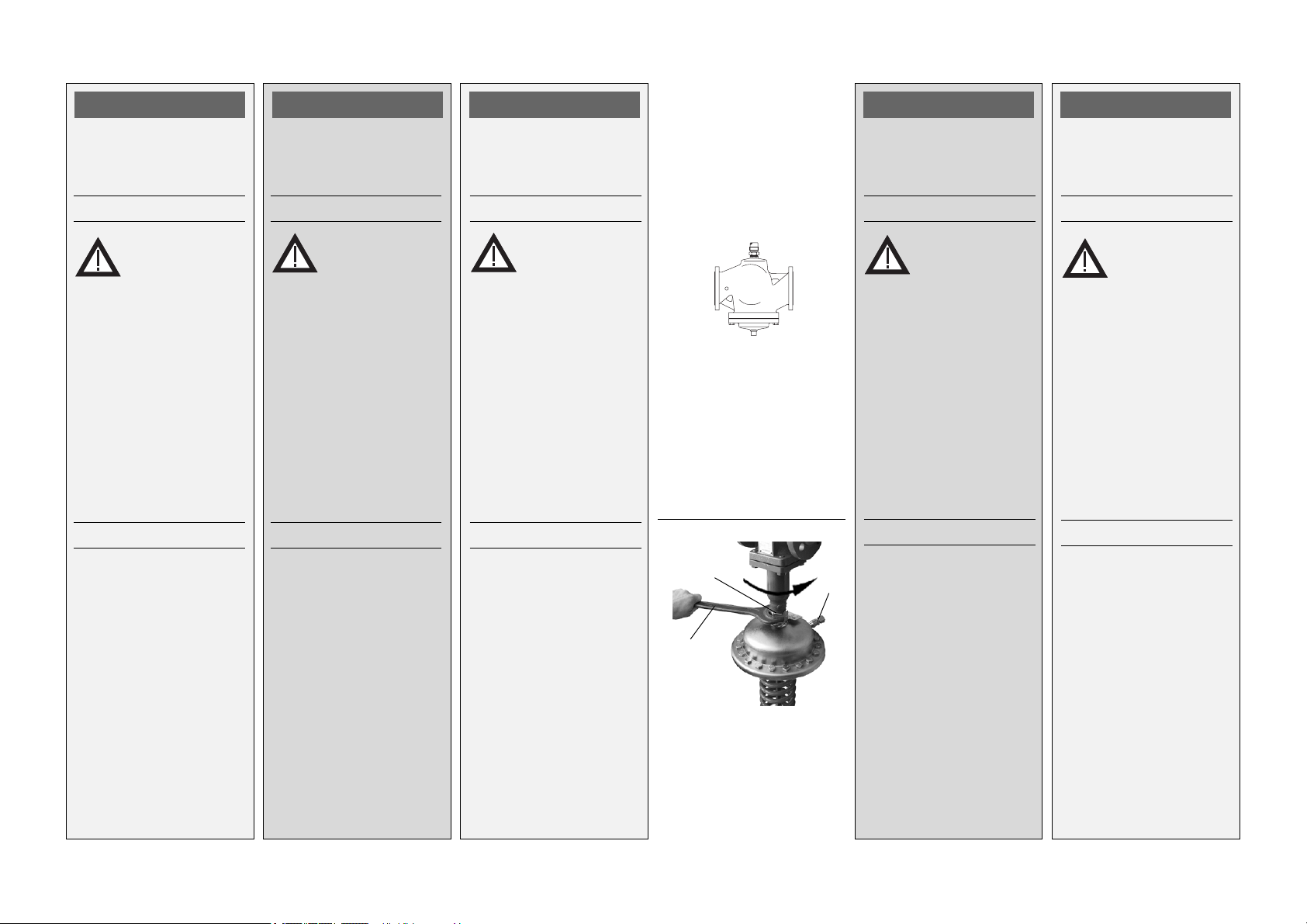
3. Screw in adjusting
throttle Ä uo to its stop.
ûValve will be closed, no
flow.
4. Select flow adjusting
curve in the diagram
(see next page).
Necessary
flow rate
No
Rotations of
adjusting throttle
5. Unscrew adjusting
throttle by this number
of raotations
6. The setting is completed,
continue with step 4.,
page 16.
Note
Å
POLSKI
3. Wkrêciæ d³awik
nastawczy Ä do oporu.
ûZawór jest zamkniêty,
brak przep³ywu.
4. Wybraæ krzyw¹ regulacji
przep³ywu z wykresu
(patrz nastêpna strona).
Wymagany
przep³yw
Iloæ obrotów
d³awika nastawczego
5. Wykrêciæ d³awik
nastawczy o odczytan¹
iloæ obrotów
6. Nastawa zosta³a
wykonana. Kolejne kroki
pkt. 4, str. 16.
Uwaga
No
Å
DEUTSCH
3.Einstelldrossel Ä bis
zum Anschlag eindrehen
ûVentil wird geschlossen,
kein Durchfluss
4.Einstelldiagramm
(siehe nächste Seite)
auswählen
erforderlicher
Volumenstrom
No
Umdrehungen
Einstelldrossel
5. Einstelldrossel um diese
Anzahl Umdrehungen
herausdrehen
6. Die Einstellung ist abgeschlossen, weiter mit
Schritt 4., Seite 16
Hinweis
Å
Ä
Å
РУССКИЙ
3.Завернуть шток
дроссельного клапана
Ä до упора.
ûКлапан будет закрыт,
расход отсутствует.
4.Выбрать на диаграмме
настроечную кривую
(см. следующую
страницу).
Необходимый расчетный
расход перемещаемой
среды
No
Число оборотов штока
дроссельного клапана
5.Отвернуть шток
дроссельного клапана
6 на указанное число
оборотов.
6.Настройка выполнена,
продолжайте, начиная
с пункта 4, на стр. 16.
Примечание
FRANCAIS
3. Serrer le limiteur Ä
jusqu’en butée
û La vanne est fermée,
pas d’écoulement.
4. Choix du diagramme
de réglage (vois page
suivante)
Débit
nécessaire -
Nombre de
tours limiteur
5. Desserrer le limiteur de
ce nombre de tours ±
6. Le réglage est terminé,
ensuite passer à la
phase 4, page 16
Indication
No
The setting may be verified
utilizing a heat meter if the
system is in operation, see
next section.
Nastawê mo¿e
zweryfikowaæ, podczas
pracy uk³adu, przy u¿yciu
licznika ciep³a, patrz
nastêpny rozdzia³.
Einstellung kann bei in
Betrieb genommener
Anlage über einen
Wärmezähler überprüft
werden, siehe nächsten
Abschnitt.
Åсли система работает,
то настройка может быть
проверена путем
использования
теплосчетчика, (см.
следующий раздел).
Le réglage peut être
vérifié par un compteur
thermique, lorsque
l’installation est en
service, voir prochain
paragraphe.
13
Type AFQ VFQ 2
V [m /h]
ENGLISH
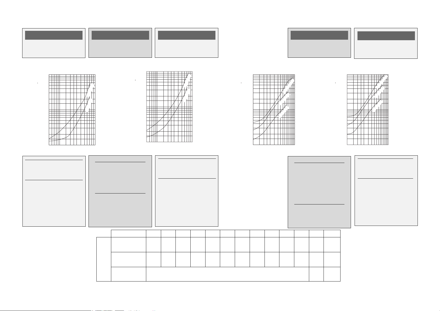
Flow Adjusting
Curves
∆∆
∆pb 0,2 bar
∆∆
10
/h]
3
7
V [m
5
3
2
1
0,7
0,5
0,3
0,2
0,1
0,5 1 2 3 4 6 8 10
The setting range of flow
rate V. depends on the restrictor differential pressure
1)
Actuator AFP with
external spring
POLSKI
Krzywe regulacji
przep³ywu
DN25/32
DN15/20
No
Zakresy nastaw
przep³ywu V w
zale¿noci od straty
cinienia na
elemencie d³awi¹cym.
1) Napêd AFP ze
sprê¿yn¹ zewnêtrzn¹
DEUTSCH
Einstelldiagramme
∆∆
∆pb 0,5 bar
∆∆
10
/h]
3
7
V [m
5
3
2
1
0,7
0,5
0,3
0,2
0,1
0,5 1 2 3 4 6 8 10
Einstellbereich Volumenstrom V. in Abhängigkeit
des Wirkdrucks
1)
Antrieb AFP mit
außenliegender Feder
DN25/32
DN15/20
No
∆∆
∆pb 0,2 bar
∆∆
100
/h]
3
70
V [m
50
30
20
10
7
5
3
2
1
12346810
РУССКИЙ
Графики настройки
расхода
DN100/125
DN65/80
DN40/50
15
No
Диапазон настройки
регулируемого
расхода V в
зависимости от
поддерживаемого
перепада давления
Dp
на дроссельном
eff
клапане
1)
Регулирующий
элемент AFP с внешней
пружиной
Diagrammes de
réglage
∆∆
∆pb 0,5 bar
∆∆
100
/h]
3
70
V [m
50
30
20
10
7
5
3
2
1
12346810
Plage de réglage débit V
en fonction de la
pression effective
FRANCAIS
DN100/125
DN65/80
DN40/50
15
No
.
V
DN 15 20 25 32 40 50 65 80 100 125 150 200 250
0,1 - 0,2 - 0,2 - 0,4 - 0,6 - 0,8 - 3 - 4 - 6 - 8 - 12 - 15 - 18 -
2347111628406380125150180
0,2 - 0,3 - 0,3 - 0,5 - 0,8 - 1,2 - 4 - 6 - 9 - 12 - 18 - 22 - 25 -
3 4,5 6 10 16 24 40 58 90 120 180 220 250
1)
[m3/h]
0,2 bar
0,5 bar
0,35 bar
24 - 34 240 340
14
Type AFQ / VFQ 2
ENGLISH
Adjust via
Heat Meter
Pre-condition:
The system must be in
operation. All units in the
system or a bypass
be completely open.
With the maximum flow
rate, the pressure
difference ∆p
control valve must at least
correspond to
= 2 x ∆p
∆p
min
See also next page,
section “Flow rate is too
low”.
1. Only with external
pressure spring Â:
Completely pre-stress
pressure spring by
turning the set-point
adjuster à up to its stop.
2. Unscrew cap nut Ä,
loosen counter nut.
À must
Á via the
v
b
POLSKI
Nastawa na podstawie
wskazañ ciep³omierza
Warunki wstêpne:
Uk³ad musi byæ w³¹czony.
Wszystkie urz¹dzenia w
uk³adzie lub bypass
musz¹ byæ ca³kowicie
otwarte.
Dla maksymalnego
przep³ywu, spadek
cinienia ∆p
zaworze regulacyjnym
Á na
v
musi wynosiæ co najmniej:
= 2 x ∆p
∆p
min
Patrz tak¿e rozdzia³
Przep³yw jest zbyt ma³y
na kolejnej stronie.
1. Tylko dla napêdów z
zewnêtrzn¹ sprê¿yny¹
regulacyjn¹ Â:
Ca³kowicie cisn¹æ
sprê¿ynê przez
dokrêcenie nakrêtki
nastawczejà do koñca.
2. Odkrêciæ os³onê Ä,
poluzowaæ
przeciwnakrêtkê.
À
b
DEUTSCH
Einstellung mit
Wärmezähler
Voraussetzung
Die Anlage muss in Betrieb sein. Armaturen in der
v
À
Á
Anlage oder ein Bypass
müssen vollständig offen
sein.
Die Druckdifferenz ∆p
über das Regelventil muss
bei max. Volumenstrom
mindestens sein:
= 2 x ∆p
∆p
min
b
siehe auch nächste Seite
Abschnitt „Volumenstrom
zu niedrig“
1. Nur bei außenliegender Druckfeder Â:
Druckfeder ganz vorspannen, durch
Drehung des Sollwertstellers à bis zum An-
schlag
2. Hutmutter Ä abschrau-
ben, Kontermutter lösen.
À
Â
36 mm
∆ p
Ä
Ã
РУССКИ
Настройка с помощью
теплосчетчика
Предварительные
условия:
Система должна быть в
рабочем режиме. Все
запорные устройства на
установках или
байпасной линии
должны быть открыты.
При расчетном расходе
v
полный перепад
давления ∆p
регулятора Á должен
Á
быть больше
= 2 õ∆p
Dð
ìèí
À
на клапане
v
b
FRANCAIS
Réglage avec compteur
thermique
Conditions
L’installation doit être en
service. Les robinets dans
l’installation ou un bypass À, doivent être
complètement ouverts.
Avec le débit max., la
différence de pression ∆p
Á dans la vanne doit être
au moins de :
= 2 x ∆p
Dp
min
voir également page
suivante, paragraphe
«débit trop faible»
b
v
См. также раздел «Что
делать, если расход
меньше расчетного?» на
следующей странице.
Â
1. Только для
регулирующего
элемента с внешней
пружиной Â :
Полностью сжать
рабочую пружину
регулирующего
1. Uniquement lorsque le
ressort de rappel  est
extérieur, le tendre
totalement, en tournant le
régleur de valeur de
consigne à jusqu’en
butée.
элемента поворотом
настроечной гайки
Ã
до упора.
2. Отвернуть крышку Ä
и ослабить контргайку.
2. Dévisser l’écrou du
capot, desserrer le
contre-écrou.
15

Ã
Type AFQ / VFQ 2
ENGLISH
3. Observe heat meter
indicator.
Tur ning to the left
increases the flow rate.
Tur ning to the right Á
reduces the flow rate.
After the adjustment has
been completed:
4. Tighten counter nut
5. Screw in cap nut
tighten.
À
à and
Â.
POLSKI
3. ledziæ wskazania
licznika ciep³a
Krêciæ w lewo
zwiêkszenia wielkoci
przep³ywu.
Krêciæ w prawo
celu redukcji wielkoci
przep³ywu.
Po dokonaniu nastawy
nale¿y:
4. Dokrêciæ
przeciwnakrêtkê
5. Nakrêciæ os³onê Ã.
À w celu
Á w
Â.
DEUTSCH
3. Anzeige des Wärmezählers beachten
Linksdrehung
den Volumenstrom
Rechtsdrehung Á reduziert den Volumenstrom
Nach abgeschlossener
Einstellung:
4. Kontermutter
ziehen
5. Hutmutter
ben und anziehen
À erhöht
 fest-
à aufschrau-
À
Á
Â
Ã
РУССКИ
3. Отметить показания на
индикаторе
теплосчетчика.
Повернуть влево
для увеличения
расхода.
Повернуть вправо Á
для снижения расхода
После выполнения
настройки:
4. Затянуть контргайку
5. Навернуть крышку Ã
и затянуть ее.
À
Â
FRANCAIS
3. Respecter les affichages
du compteur thermique
La rotation à gauche
augmente le débit
La rotation à droite
réduit le débit
Lorsque le réglage est
terminé :
4. Serrer le contre-écrou
À
Á
Â
5. Visser l’écrou du capot
à et le serrer
6. Cup nut may be
sealed
Ä.
6. Os³ona mo¿e zostaæ
zaplombowana Ä.
6. Hutmutter kann plombiert werden
Ä
Ä
6. Крышка может быть
опломбирована
Ä
6. L’écrou du capot peut
être plombé Ä
16

Type AFQ / VFQ 2
ENGLISH
What to do when the flow
rate is low?
Remedy:
1. Verify adjustment, see
section abvove.
2. Check differential pressure via the control valve.
min. differential pressure ∆ p
∆p
v
∆pbeffective pressure [bar]
V max. flow rate
kvs[m3/h]
:
v
∆p
b
0.2
= 0.5 + (V/kvs)
0.35
(see typeplate)
[m3/h]
2
POLSKI
Co zrobiæ gdy wielkoæ
przep³ywu jest zbyt ma³a?
Rozwi¹zanie:
1. Zweryfikowaæ nastawê,
patrz rozdzia³y wczeniej.
2. Sprawdziæ spadek
cinienia na zaworze
regulacyjnym. Min.
Spadek cinienia ∆ p
∆p
b
0,2
= 0,5 + (V/kvs)
∆p
v
0,35
∆p
strata cinienia na
b
elemencie
d³awi¹cym [bar]
(patrz tabliczka
znamionowa)
V max. przep³yw [m
[m3/h]
k
vs
:
v
2
3
/h]
DEUTSCH
Volumenstrom zu niedrig,
was tun?
Maßnahme:
1. Einstellung prüfen,
siehe Abschnitt
zuvor
2. Differenzdruck über das
Regelventil prüfen
min. Differenzdruck ∆ p
∆p
b
0,2
= 0,5 + (V/kvs)
∆p
v
0,35
∆pbWirkdruck [bar]
(siehe Typenschild)
V max. Volumenstrom
[m3/h]
kvs[m3/h]
2
РУССКИ
Что делать, если
расход меньше
расчетного?
Мероприятия по
устранению:
1.Проверить настройку,
(см. раздел,
приведенный выше).
:
v
2.Проверить перепад
FRANCAIS
Débit trop faible, que faire
?
Mesures :
1. Vérifier le réglage, voir
paragraphe précédent
2. Vérifier la pression
différentielle dans la
vanne, pression
différentielle min. ∆ pv:
давления на
регулирующем
клапане. Мин. перепад
давления ∆ p
∆p
0,2
= 0,5 + (V/kvs)
∆p
v
:
v
b
∆p
2
∆p
b
0,2
= 0,5 + (V/kvs)
v
0,35
2
0,35
∆p
Pression effective
b
(bar)(voir plaque
ãäå:
∆p
давление,
b
поддерживаемое на
signalétique)
дроссельном клапане,
бар (см. фирменную
V Débit max. (m3/h)
табличку),
V расчетный расход
перемещаемой среды,
3
/÷,
ì
пропускная
k
vs
способность клапана
kvs (m3/h)
регулятора, м3/ч.
17
 Loading...