

Page 1
Data sheet
Pressure independent control valve with integrated flow limiter
AFQMP 2 - return and flow mounting, adjustable setting
Description
virtus.danfoss.com
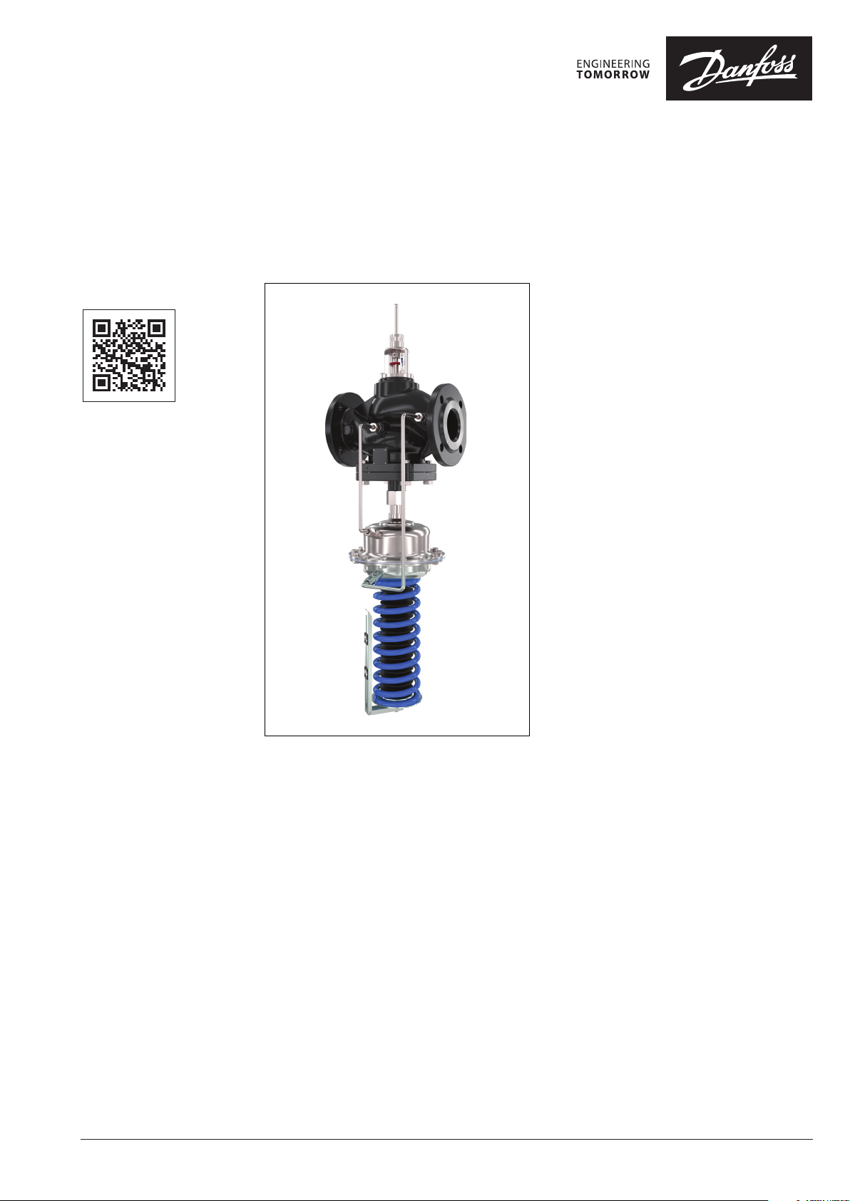
AFQMP 2 is a self-acting flow controller with
integrated control valve and with pressure
actuator with adjustable spring, developed for
the use in district heating / cooling systems. The
controller prevents flow to exceed set max flow.
Pressure actuator with adjustable spring enables
adjustment of differential pressure over the
control cone from 0.1 to 1 bar. Increased flows
can be provided. In a combination with electrical
actuators AMV(E) and ECL electronic controllers
the flow and temperature can be controlled to
achieve highest energy savings.
AFQMP 2
limiter, connection neck for electrical actuator and
a pressure actuator with one control diaphragm.
Controllers are used together with Danfoss
electrical actuators:
• AFQMP 2 PN 16/25/40 DN 65-250
- AMV(E) 655 without spring return function
- AMV(E) 658 SD 2) spring return function and
- AMV(E) 659 SD 1) spring return function;
- AMV(E) 55
• AFQMP 2 PN 16/25/40 DN 65 -125
- AMV(E) 56
1)
DIN approve d (according to EN 1457)
2)
not DIN approved
Together with Danfoss intelligent electrical
actuator AMEi 6 intelligent optimization
functions are available:
iSET-intelligent substation efficiency
iNET-intelligent pump optimization
Main data:
• DN 65-250
• kVS 60-800 m3/h
• Flow range 4.2-630 m3/h
• PN 16, 25, 40
• Differential pressure over the flow control
• Temperature:
• Connections: Flange
• AFQMP 2 combined with AMV(E) 659 SD have
has a control valve with adjustable flow
and with manual operation;
manual operation;
optimization
cone ∆pCV:
0.1-1 bar (adjustable by the spring)
- Circulation water / glycolic water up to 30 %:
2 … 150°C
been DIN approved according to EN 14597.
© Danfoss | 2022.01
AI343441104258en-010103 | 1
Page 2
Data sheet AFQMP 2
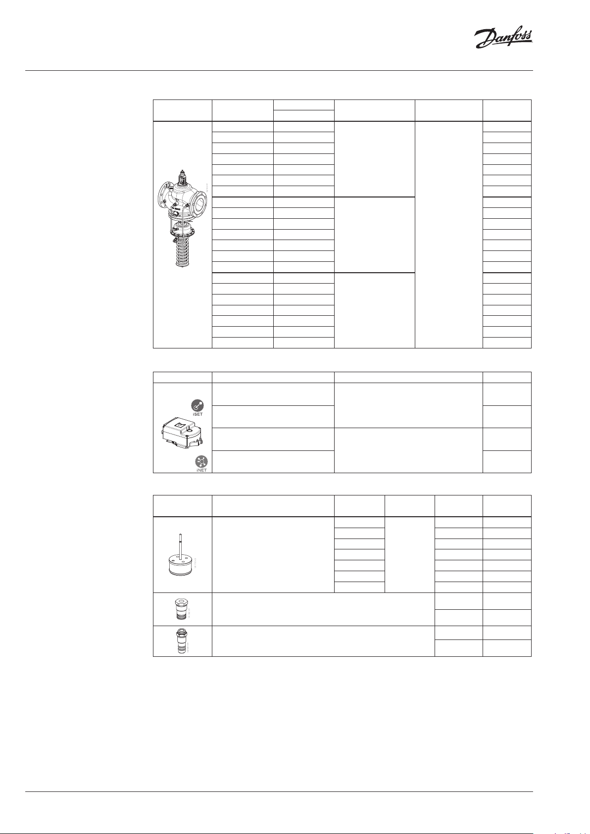
Ordering
Example:
Flow controller with integrated
control valve for flow rate, DN65,
kVS 60, PN 16, T
- 1× AFQMP 2 DN 65 controller
Code No.: 003G5560
The controller will be delivered
completely assembled, inclusive
impulse tubes between valve and
actuator. Electrical actuator AMV(E)
must be ordered separately.
150 °C, flange
max
AFQMP 2 Controller
Q
Picture DN
65 27- 61
80 40 -100 003G5561
100 60 -138 003G5562
125 100 -230 003G5563
150 130 -290 003G5564
200 180-450 003G5565
250 280-630 003G5566
65 27- 61
80 40 -100 003G5571
100 60 -138 003G5572
125 100 -230 003G5573
150 130 -290 0 03G55 74
200 180-450 003G5575
250 280-630 003G 5576
65 27- 61
80 40 -100 003G 5581
100 60 -138 003G5582
125 100 -230 003G5583
150 130 -290 003G5584
200 180-450 003G5585
250 280-630 003G5586
max
pCV= 0.1-1 bar
PN Connection Code No.
16
25
40
Flange EN 1092-1
Accessories
Picture Type designation Description Code No.
AMEi 6 iSET
el actuator 230 V
AMEi 6
iSET
el actuator 24 V
AMEi 6 iNET
el actuator 230 V
AMEi 6 iNET
el actuator 24 V
Intelligent p actuator with iSET function
Intelligent p actuator with iNET function
003G5560
003G5570
003G5580
082G4300
082G4301
082G4302
082G4303
Service kits
Picture Typ e
Pressure control insert VFG/Q 221
k
VS
(m3/h)
60
80 80 003G18 08
160 100 003 G1809
250 125 003 G1810
380 150 003 G1811
650 200 003 G1812
800 250 00 3G1813
Flow stuffing box VFG/Q 22(1)
Pressure stuffing box VFG/ Q 22(1)
PN DN Code No.
65 003G1807
16/2 5/40
65 -125 00 3G1720
150-250 00 3G1721
65 -125 003G1730
150-250 003G1731
2 | AI343441104258en-010103
© Danfoss | 2022.01
Page 3
Data sheet AFQMP 2
AFQMP 2 Actuator
Picture
Actuator size
(cm)
∆p setting range
(bar)
for DN
Code No.
PN 16 PN 40
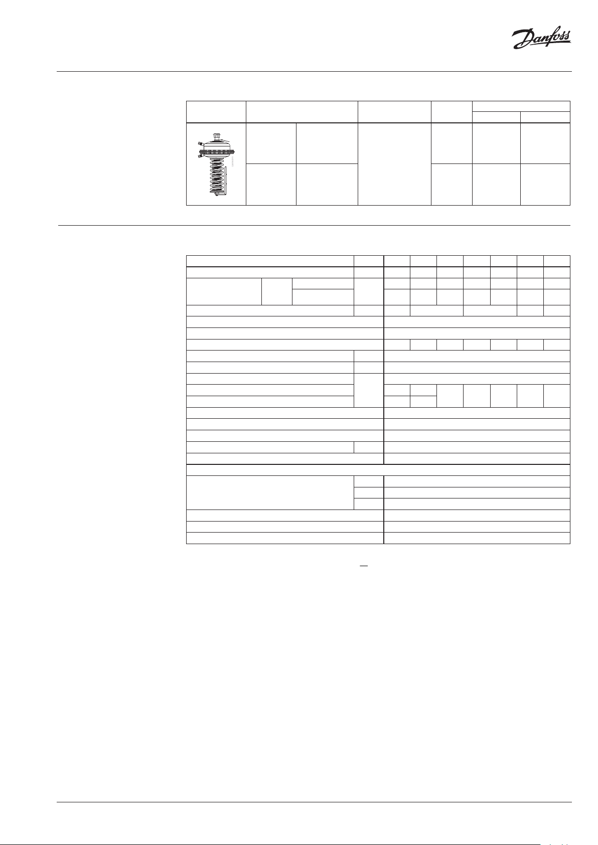
Technical data AFQMP 2 valve
kVS value m3/h 60 80 160 250 380 650 800
Range of max. flow
settings Q
Stroke mm 12 19 23 28 32
Control valve authority 1 (100 %) in the range of flow setting
Control characteristic linear-split
Cavitation factor z 0.65 0.55 0.4 0.4 0.4 0.4 0.3
Leakage acc. to standard IEC 534 % of k
Nominal pressure PN 16, 25, 40
Min. differential pressure
Max. dif ferential pressure PN 16 16 16
Max. dif ferential pressure PN 25/40 20 20
Pressure relievement system Chamber relieved
Media Circulation water / Glycolic water up to 30 %
Media pH Min .7, ma x.1 0
Media temperature °C 2 … 150
Connections Flange
Valve body
Valve seat DP, CV Stainless steel, mat. No. 1.4021
Valve cone DP, CV Stainless steel, mat. No. 1.4021
Sealing DP, CV EPDM
1)
DP-dif f. pressure over the pressure contro l cone, CV-diff. pres sure over the flow control cone , ∆p
2)
Required dif ferential pressure for d esired flow Q ->
160 blue
65 -125 003G5612 003G5622
0.1-1
320 orange 150-250 003G5610 003G5620
Nominal diameter DN 65 80 100 125 150 200 250
∆pCV 1) = 0.1 bar
max
∆pCV 1) = 1 bar 61 10 0 13 8 230 290 450 630
m3/h
bar
27 40 60 100 130 180 280
VS
≤ 0.01
see remark
2)
15 15 12 10 10
Materials
PN 16 Grey cast iron EN-GJL-250 (GG-25)
PN 25 Ductile iron EN- GJS-400 -18-LT (GGG-40.3)
PN 40 Cast steel GP240GH (GS-C 25)
- diff. pressur e over AFQMP 2 valve
p
AFQMP
k
2
Q
p
, ∆pCV can be set bet ween 0.1 - 1 bar
CV
VS
AFQMP
© Danfoss | 2022.01
AI343441104258en-010103 | 3
Page 4
Data sheet AFQMP 2
p
at z = 0,2 ... 0,6 [bar]
Inlet pressure bar p [bar]
z =
Example :
100
200
300
400
500
600
700
00.1 0.20.3 0.40.5 0.60.7 0.80.9 1
AFQMP 2 actuator
Actuator size cm
Max. operational pressure
Differential pressure over the f low control
cone
∆p
CV
Housing Steel, mat. No. 1.0345, zinc plated
Diaphragm EPDM (Rolling; fibre enforced)
Impulse tube Stainless steel tube Ø10 × 0.8 mm
Range of max. flow settings
Qmax
(m3/h)
For valve DN 65 80 100 12 5 15 0 200 250
2
160 320
16 or 40
bar
0.1-1 (adjustable)
Materials
DN250
DN200
DN15 0
DN125
Operating area
0
4)
Set by the spring on the adjustable pressure actuator
Maximum allowed differential pressure over the controller (p
max
T = 90°C
T = 110°C
T = 100°C
) at different cavitation factors (z)
max
p = 6 bar
T = 140°C
z = 0,4
= 1,35 bar
p
max
T = 80°C
T = 130°C
T = 140°C
DN100
DN80
DN65
∆pCV
(bar)
4)
4 | AI343441104258en-010103
[bar]
max
p
T = 150°C
© Danfoss | 2022.01
Page 5

Data sheet AFQMP 2
Application principles
- Return mounting
- Flow mounting
AFQMP 2
Direct-connected heating system
AFQMP 2
Indirectly connected heating system
AFQMP 2
AFQMP 2
Direct-connected heating system Indirectly connected heating system
Installation positions
Note!
Installation positions for electrical
actuators AMV(E) have to be observed
as well. Please see relevant Data sheet.
© Danfoss | 2022.01
AI343441104258en-010103 | 5
Page 6

Data sheet AFQMP 2
Pressure temperature diagram
PN 16
EN - GJL- 250
(GG -25)
150
PN 25
EN-GJS-400
(GGG-40.3)
150
PN 40
EN-GP-240-GH
(GS- C 25)
150
Maximum allowed operating pressure as a function of media temperature (according to EN 1092-2)
6 | AI343441104258en-010103
© Danfoss | 2022.01
Page 7

Data sheet AFQMP 2
0
10
20
30
40
50
60
70
80
90
100
0 12345678910
Design
1. Valve body
2. Flow control insert
3. Flow stuffing box
4. Max. flow limitation nut
5. Valve seat
6. Pressure control insert
7. Pressure actuator
8. Pressure actuator diaphragm
9. Pressure actuator spring
10. Diaphragm excess pressure
safety valve
11. Flow control cone (CV)
12 . Pressure control cone (DP)
13 . Impulse tube
14 . Union nut
15 . Cover
16. Connection for electrical
actuator
17. Pressure stuffing box
18. Setting scale
19. Setting indicator
20. Differential pressure setting
nut
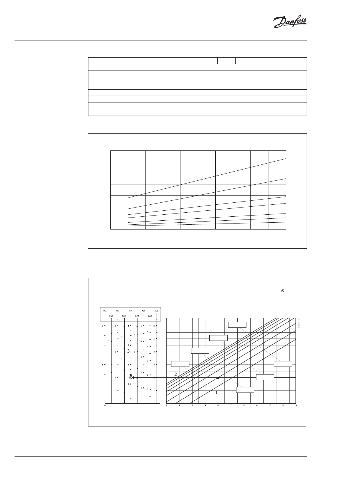
Settings Differential pressure setting
Flow setting
Flow limitation is being done by the adjustment
of the max. flow limitation nut. The adjustment
can be performed on the basis of flow limiting
diagram (see relevant instructions) and/or by
the means of heat meter. Flow limiting curves
in diagrams represent informational values, for
Differential pressure setting is being done by the
adjustment of the setting spring for diff. pressure
control. This is done by rotating the differential
pressure setting nut. Set differential pressure
should be checked by observing the pressure
indicators.
more accurate flow limitation setting use flow/
heat meter.
Flow limiting
turns indicator
1 revoluti on =360°
DN 65
/h
3
flow m
© Danfoss | 2022.01
p
No. of revolutions
= max
b
p
= min
b
AI343441104258en-010103 | 7
Page 8

Data sheet AFQMP 2
10
11
120
012345678910 11 12 13 14
0
20
40
60
80
100
120
140
160
012345678910111213
0
20
40
60
80
100
120
140
160
180
200
220
240
012345678910 11 12 13 14 15
0
20
40
60
80
100
120
140
160
180
200
220
240
260
280
300
320
0123456789101112131415
Flow limiting (continuous)
3
/h
3
flow m
/h
flow m
0
DN 80
0
90
80
70
60
50
40
30
20
10
0
No. of revolutions
= max
b
p
p
b
= min
DN 10 0
= max
b
p
= min
b
p
/h
3
flow m
/h
3
flow m
© Danfoss | 2022.01
DN 125
DN 150
No. of revolutions
b
p
No. of revolutions
No. of revolutions
= max
p
= min
b
p
p
b
= max
b
= min
AI343441104258en-010103 | 8
Page 9

Data sheet AFQMP 2
500
10
15
20
25
30
35
40
45
50
55
60
65
700
21
Flow limiting (continuous)
450
DN 200
400
350
300
250
/h
3
200
150
flow m
100
50
0
012345678910 11 12 13 14 15 16 17 18 19
No. of revolutions
0
DN 250
0
0
0
0
0
/h
3
0
0
0
flow m
0
0
0
50
0
012345678910 11 12 13 14 15 16 17 18 19 20
p
= 0.7 bar
b
p
b
p
= 0.1 bar
= 0.7 bar
b
= 0.1 bar
p
b
Function Flow control
No. of revolutions
Flow control cone adjusts the flow by opening
and closing. This action is provided by an electric
actuator. The max flow is limited by limiting the
maximal opening of the flow control cone. This
is done by rotating the flow limitation nut. The
pressure independent flow control is achieved by
maintaining a constant differential pressure over
the flow control cone.
The differential pressure over the flow control
cone is lead to the pressure actuator diaphragm
through the impulse tubes. It is factory preset.
The opening/closing of the pressure control cone
is performed by changing differential pressure
over the diaphragm.
When differential pressure over the flow control
cone:
a) rises, the pressure control cone takes over the
exceeded differential pressure by closing, until
set differential pressure over the flow control
cone is reached.
b) drops, the pressure control cone compensates
the missing differential pressure by opening,
until set differential pressure over the flow
control cone is reached.
Pressure actuator diaphragm is equipped
with excess pressure safety valve to protect
diaphragm from the damages caused by too
high differential pressure.
Differential pressure control
Is achieved by maintaining a constant differential
pressure over the control valve.
The differential pressure over the control valve is
lead to the pressure actuator diaphragm through
the impulse tubes.
The opening/closing of the pressure control cone
is performed by changing differential pressure
over the diaphragm.
When differential pressure over the control valve:
a) rises, the pressure control cone takes over the
exceeded differential pressure by closing, until
set differential pressure over the control valve/
application is reached.
b) drops, the pressure control cone compensates
the missing differential pressure by opening,
until set differential pressure over the control
valve/application is reached.
The pressure actuator diaphragm is equipped
with excess pressure safety valve to protect
diaphragm from the damages caused by too
high differential pressure.
9 | AI343441104258en-010103
© Danfoss | 2022.01
Page 10

Data sheet AFQMP 2
Dimensions
AFQMP 2 pressure actuator
Ø295
AMEi 6 iSET/iNET electric actuator
100
140
mi n. 150
220
770
39 51 54
3
H
mi n. 150
AMEi 6 intellig ent
actuator wit h iSET/iNET
functionality should be
622
mi n. 150
ordered sep arately
min. 250
mi n. 150
L H1H2H3HAIValve weight (kg)
DN
65 290 670 520 545
80 310 670 520 545 44 56 59
100 350 705 545 475 805 63 76 81
125 400 710 580 610 810 82 94 102
150 480 775 610 635 875 138 159 174
200 600 810 665 695 910 245 267 295
250 730 870 680 705 970 397 424 478
2
H
mm PN 16 PN 25 PN 40
© Danfoss | 2022.01
Ai
H
AMV(E) 55, 56/ AMEi 6
iSET/iNET AFQMP 2
DN 65-125
Ai
H
AMV(E) 65X/ AMEi 6
iSET/ iNET AFQMP 2
DN 65-250
1
H
L
AMV(E) 55, 56/AFQMP 2
DN 65-125
AI343441104258en-010103 | 10
1
H
L
AMV(E) 65X/AFQMP 2
DN 65-250
Page 11

Data sheet AFQMP 2
11 | AI343441104258en-010103
© Danfoss | DCS-SGDPT/SI | 2022.01
 Loading...