

Page 1
Data sheet
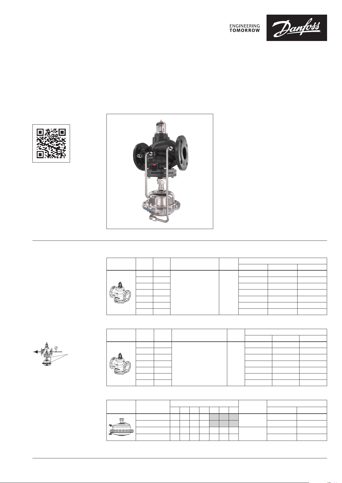
Flow controller (PN 16, 25, 40)
AFQ 2 / VFQ 22(1) – return and flow mounting
Description
virtus.danfoss.com
Ordering
Example 1:
Flow controller; DN 65; kVS 60; PN 16;
metallic sealing; flow restrictor
∆pb 0.2 bar; T
– 1× VFQ 22 DN 65 valve
Code no: 065B5570
– 1× AFQ 2 actuator
Code no: 003G5600
– 1× AFQ DN 65 impulse tubes
Code no: 003G18 43
150 °C; flange;
max
VFQ 22 Valve (metallic sealing cone)
Picture
DN
(mm)
100 160 065B5572 065B5579 065B5586
125 250 065B5573 065B5580 065B5587
150 380 065B 5574 065B5581 065B5588
200 650 065B5575 0 65B5582 065B5589
250 800 065B5576 065B5583 065B5590
k
VS
(m3/h)
65 60
80 80 065B5571 065B5578 065B5585
Flanges acc. to EN 1092-1 150
Connections
The controller is a self-acting flow controller
primarily for use in district heating systems. The
controller closes when set max. flow is exceeded.
The controller has a control valve with adjustable
flow restrictor and an actuator with one control
diaphragm.
Further on two valve versions are available:
∙ VFQ 22 with metallic sealing cone
∙ VFQ 221 with soft sealing cone
Main data:
∙ DN 65-250
∙ kVS 60-800 m3/h
∙ Flow range 5.6-500 m3/h
∙ PN 16, 25, 40
∙ Flow restrictor ∆pb: 0.2 bar or 0.5 bar
∙ Temperature: – Circulation water / glycolic
water up to 30%: 2 … 150°C
∙ Connections: Flange
T
(°C)
max.
PN 16 PN 25 PN 40
065B5570 065B5577 065B558 4
Code No.
Products will be delivered
separately.
Impulse tubes AFQ 2
VFQ 221 Valve (soft sealing cone)
Picture
DN
(mm)
65 60
80 80 065B5601 065B5608 06 5B5615
100 160 065B5602 065B5609 0 65B5616
125 250 065B5603 065 B5610 0 65B 5617
150 380 065B5604 0 65B5 611 065 B5618
200 650 065B5605 0 65B5 612 065B5 619
250 800 065B5606 0 65B5 613 065B5620
k
VS
(m3/h)
Connections
Flanges acc. to EN 1092-1 150
T
(°C)
max.
PN 16 PN 25 PN 40
065B5600 065B5607 0 65B5 614
Code No.
AFQ 2 Actuator
Picture
Δp setting range
(bar)
0,2
0,5
0,2
0,5
Possible combinations with DN
65 80 100 125 15 0 200 250 PN 16 PN 40
- - -
- - - 003G5601 003G5603
Actuator size
(cm2)
160
320
Code No.
003G5600 003G5602
003G5596 003G5598
003G5597 003G5599
© Danfoss | 2022.04 AI373552176233en-010103 | 1
Page 2
Data sheet AFQ 2/VFQ 22(1)
Ordering (continuous) Impulse tubes
Picture Typ e For controller
Impulse tubes AFQ 2
Service kits
Picture Typ e
Pressure control
insert VFQ/Q/22
Pressure control
insert VFQ/Q/221
Pressure stuffing box VFQ/Q/221
for valve DN
(mm)
65
80 003 G1850
100 003 G1851
125 003G18 52
150 00 3G1853
200 003 G1854
250 003 G1855
k
VS
(m3/h)
60
80 80 00 3G1801
160 100 003 G1802
250 125 003G1803
380 150 003G18 04
650 200 003G180 5
800 250 003 G1806
60 65 0 03G1807
80 80 003 G1808
160 100 003 G1809
250 125 003G1810
380 150 00 3G18 11
650 200 003 G1812
800 250 0 03G1813
PN DN Code No.
16/2 5/40
PN
(bar)
40
65 003G1800
65 -125 003G1730
150-250 003G1731
Code No.
003 G1843
Installation position
The controllers can be installed in any position.
2 | AI373552176233en-010103 © Danfoss | 2022.04
Page 3
Data sheet AFQ 2/VFQ 22(1)
p
at z = 0,2 ... 0,6 [bar]
Inlet pressure bar p [bar]
z =
Example :
2
Technical data
VFQ 22(1) Valve
Nominal diameter DN 65 80 100 125 150 200 250
kVS value of p controller
Range of max. flow
setting
pb 1) = 0.2 bar
pb 1) = 0.5 bar
from 5.6 8 12.6 20 32 54 72
m3/h
to 28 40 63 100 160 270 360
from 8,4 12 19 30 48 68 100
to 42 60 95 150 240 340 500
60 80 160 250 380 650 800
Cavitation factor z 0.65 0.55 0.4 0.4 0.4 0. 35 0.3
Leakage acc. to standard
IEC 534 (% of kVS)
VFQ 22 ≤ 0.03 ≤ 0.05
VFQ 221 ≤ 0.01
Nominal pressure PN 16, 25, 40
Min. differential pressure
Max. differential pressure PN 16 16
bar
Max. differential pressure PN 25/40 20
see remark
15 15 12 10 10
2)
Pressure relievement system Chamber relieved
Media Circulation water / Glycolic water up to 30 %
Media pH Min.7, ma x.1 0
Media temperature °C 2 … 150
Connections Flange
Materials
PN 16 Grey cast iron EN-GJL-250 (GG-25)
Valve body
PN 25 Ductile iron EN-GJS-400(GGG-40.3)
PN 40 Cast steel GP240GH (GS-C 25)
Valve seat / Valve cone Stainless steel, mat. No. 1.4021
Sealing EPDM
1)
∆pb – differe ntial pressure over flow rest rictor
2)
For flows sma ller than Q
->
p
max
min
Q
p
k
VS
b
AFQ 2 Actuator
bar
2
160 320
16, 4 0
Materials
Actuator size cm
Max. operating pressure
Flow restrictor differential pressure pb 0. 2 / 0.5
For valve DN 65 -125 65-2 50
Actuator housing Steel, mat. No. 1.0345, zinc plated
Control diaphragm EPDM (Rolling; fibre enforced)
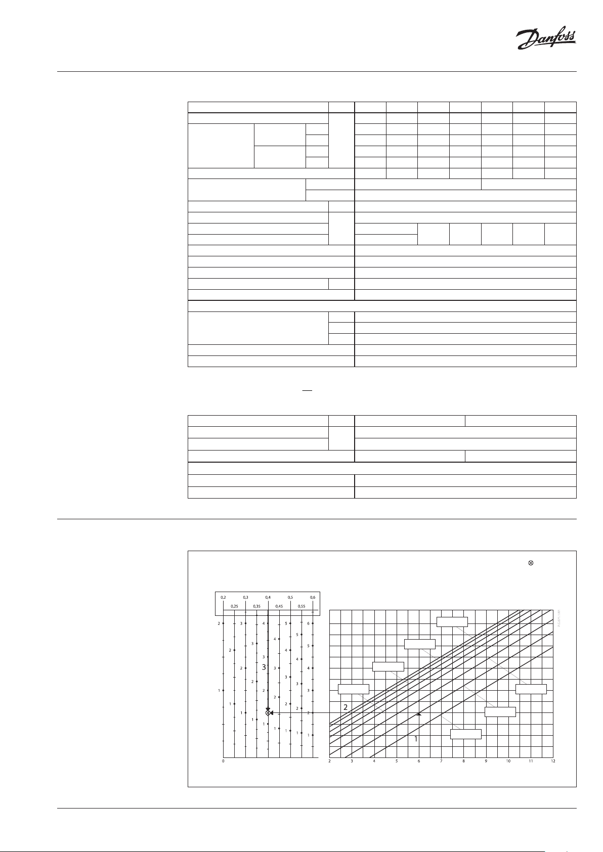
Operating area
Maximum allowed differential pressure over the controller (p
max
T = 90°C
T = 100°C
T = 110°C
[bar]
max
p
) at different cavitation factors (z)
max
p = 6 bar
T = 140°C
z = 0,4
= 1,35 bar
p
max
T = 80°C
T = 130°C
T = 140°C
T = 150°C
AI373552176233en-010103 | 3© Danfoss | 2022.04
Page 4
Data sheet AFQ 2/VFQ 22(1)
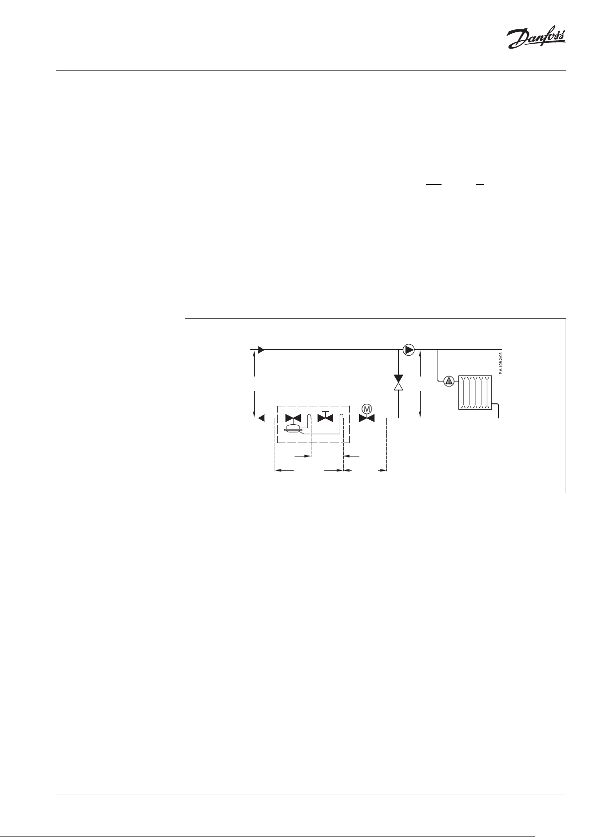
Application principles
– Return mounting
Direct-connected heating system Indirectly connected heating system
– Flow mounting
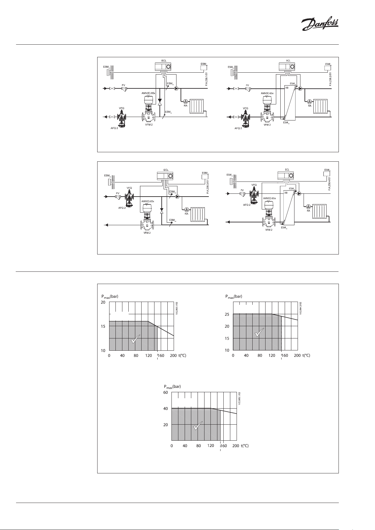
Pressure temperature
diagram
Working area is below P-T line and it
ends at T
for each valve
max
Direct-connected heating system Indirectly connected heating system
PN 25
PN 16
EN - GJL- 250
(GG -25)
150
150
Maximum allowed operating pressure as a function of media temperature (according to EN 1092-2)
PN 40
EN-GP-240-GH
(GS- C 25)
EN-GJS-400
(GGG-40.3)
150
Maximum allowed operating pressure as a function of media temperature (according to EN 1092-1)
4 | AI373552176233en-010103 © Danfoss | 2022.04
Page 5
Data sheet AFQ 2/VFQ 22(1)
2
2
0,5 > 0,37
Sizing
– Directly connected heating
system
Example 1
Motorised control valve (MCV) for mixing circuit
in direct-connected heating system requires
differential pressure of 0.5 bar (50 kPa) and flow
less than 25.000 l/h.
Given data:
Q
= 25 m3/h (25.000 l/h)
max
∆p
= 1 bar (100 kPa)
min
1)
∆p
= 0.1 bar (10 kPa)
circuit
∆p
= 0.5 bar (50 kPa) selected
MCV
2)
∆p
= 0.2 bar (20 kPa)
b
Remark:
1)
∆p
corresponds to th e required pump pressur e in the heating
circuit
circuit and is not to b e considered when sizing th e AFQ 2.
2)
∆pb is differe ntial pressure over flow rest rictor.
The total (avaliable) pressure loss across the
controller is:
∆p
= ∆p
AFQ, A
∆p
= 0.5 bar (50 kPa)
AFQ, A
min
− ∆p
= 1 – 0.5
MCV
Q
max
Possible pipe pressure losses in tubes, shutoff fittings, heatmeters, etc. are not included.
The min. required differential pressure across
the selected controller is calculated from the
formula:
kv value is calculated according to formula:
∆p
∆p
∆p
AFQ,min
AFQ,min
AFQ, A
=
=0,37
>∆p
Q
max
k
VS
AFQ,min
+∆pb=
25
+0,2
60
kv = 45.6 m3/h
Solution:
The example selects AFQ 2 DN 65, kVS value 60,
flow setting range 5.6-28 m3/h.
p
min
AFQ 2
p
b
p
AFQ
p
MCV
p
circuit
AI373552176233en-010103 | 5© Danfoss | 2022.04
Page 6

Data sheet AFQ 2/VFQ 22(1)
( ) ( )
Sizing (continuous)
– Indirectly connected heating
system
Example 2
Motorised control valve (MCV) for indirectly
connected heating system requires differential
pressure of 0.5 (50 kPa) bar and flow less than
24.000 l/h.
Given data:
Q
= 24 m3/h (24.000 l/h)
max
∆p
= 1.0 bar (100 kPa)
min
∆p
∆p
∆p
Remark:
1)
∆pb is differe ntial pressure over flow rest rictor
= 0.1 bar (10 kPa)
exchanger
= 0.5 bar (50 kPa) selected
MCV
1)
= 0.2 bar (20 kPa)
b
The total (avaliable) pressure loss across the
controller is:
∆p
= ∆p
AFQ, A
∆p
= 1.0 − 0.1 − 0.5
AFQ, A
∆p
= 0.4 bar (40 kPa)
AFQ, A
min
− ∆p
exchanger
− ∆p
MCV
Possible pipe pressure losses in tubes, shut-off
fittings, heatmeters, etc. are not included.
The min. required differential pressure across
the selected controller is calculated from the
formula:
Solution:
The example selects AFQ 2 DN 65, kVS value 60,
flow setting range 5.6-28 m3/h.
p
Q
max
min
AFQ 2
p
b
p
AFPQ
p
MCV
p
exchanger
6 | AI373552176233en-010103 © Danfoss | 2022.04
Page 7
Data sheet AFQ 2/VFQ 22(1)
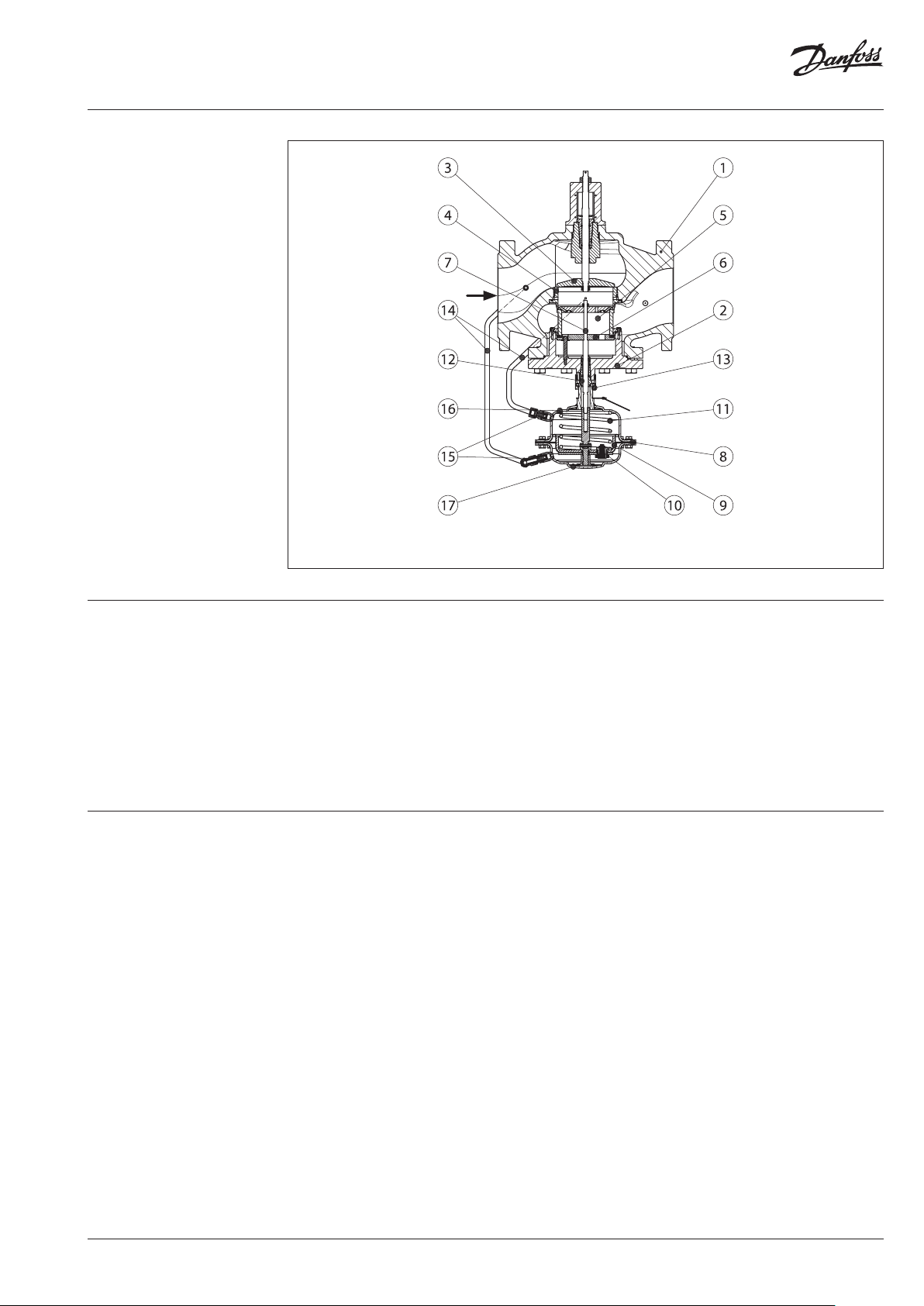
Design
1. Valve body
2. Cover
3. Adjustable flow restrictor
4. Valve seat
5. Valve insert
6. Pressure relieved valve cone
7. Valve stem
8. Actuator
9. Control diaphragm for
differential pressure and flow
control
10. Excess pressure safety valve
11. Built in spring for differential
pressure and flow control
12. Stuffing cone
13. Union nut
14. Impulse tube
15. Compression fitting for
impulse tube
16. Upper casing of diaphragm
17. Lower casing of diaphragm
AFQ 2 VFQ 22(1), DN 65-250
Function
Settings
Flow volume causes pressure drop across the
adjustable flow restrictor. Resulting pressures
are being transferred through the impulse tubes
to the actuator chambers and act on control
diaphragm for flow control. The flow restrictor
diff. pressure is controlled and limited by means
of built-in spring for flow rate control. Control
valve closes on rising differential pressure and
opens on falling differential pressure to control
max flow.
Flow setting
Flow setting is being done by the adjustment of
the flow restrictor position. The adjustment can
be performed on the basis of flow adjustment
diagram (see relevant instructions) and/or by the
means of heat meter.
AI373552176233en-010103 | 7© Danfoss | 2022.04
Page 8

Data sheet AFQ 2/VFQ 22(1)
Dimensions
L
V
H
H
B
VFQ 22(1) DN 65-250
VFQ 22, VFQ 221 Valves
Weight
PN 16 PN 25 PN 40
DN
L B H H
V
mm kg
65 290 237 473 396 28 29 31
80 310 237 473 396 33 34 36
100 350 272 5 47 472 52 53 57
125 400 268 582 514 71 72 79
150 480 326 670 610 12 3 126 135
200 600 3 61 773 713 230 236 286
250 730 419 843 783 382 392 4 41
A
H
AFQ 2 Actuator
ØA
AFQ 2 Actuator
Size ØA H
2
cm
A
mm kg
160 230 200 8 10
320 300 200 13 19
Total installation heig ht of the controller (VFQ 22(1) valve
+ AFQ 2 pressure act uator) is sum of HV and H
Weight
PN 16 PN 40
A
Ø10
40
G⁄
SW19
Compression fitting
© Danfoss | DCS-SGDPT/SI | 2022.048 | AI373552176233en-010103
 Loading...