

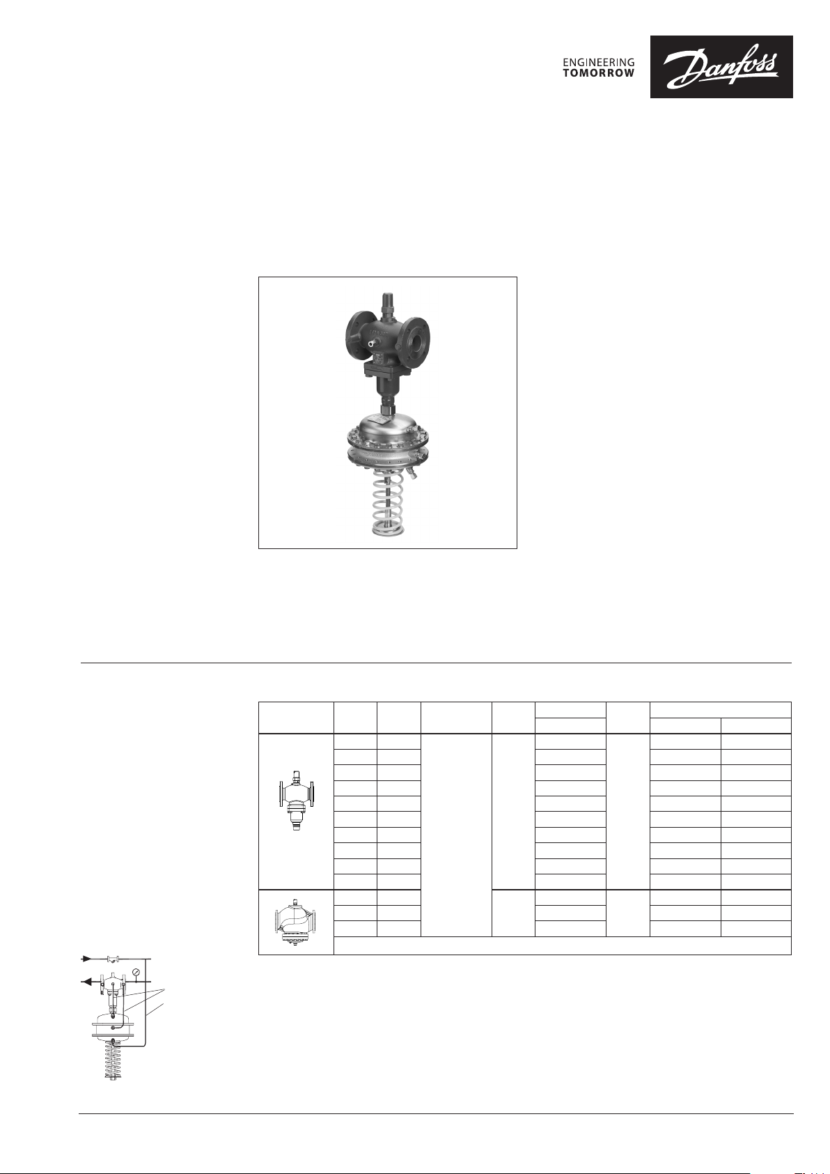
Data sheet
Differential pressure and flow controller (PN 16, 25, 40)
AFPQ / VFQ 2(1) - return mounting, adjustable setting
AFPQ 4 / VFQ 2(1) - flow mounting, adjustable setting
Description
The controller is a self-acting differential pressure
and flow controller primarily for use in district
heating systems. The controller closes on rising
differential pressure or when set max. flow is
exceeded.
The controller has a control valve with adjustable
flow restrictor, an actuator with two control
diaphragms and spring for differential pressure
setting. Differential pressure control and flow
control are independent.
Further on two valve versions are available:
– VFQ 2 with metallic sealing cone
– VFQ 21 with soft sealing cone (on special
request)
Main data:
∙ DN 15 -250
∙ kVS 4.0-400 m3/h
∙ Flow range: 0.1-250 m3/h
∙ PN 16, 25, 40
∙ Setting range: 0.1-0.7 bar / 0.15-1.5 bar
∙ Flow restrictor pb: 0.2 bar or 0.5 bar
∙ Temperature:
– Circulation water / glycolic water up to 30 %:
2 … 150/200 °C
∙ Connections:
– Flange
Ordering
Example 1:
Differential pressure and flow
controller; return mounting;
DN 15; kVS 4.0; PN 16; metallic
sealing; setting range 0.1-0.7 bar;
flow restrictor ∆ pb 0.2 bar;
T
150 °C; flange;
max
– 1× VFQ 2 DN 15 valve
Code no: 065B2654
– 1× AFPQ actuator
Code no: 00 3G10 2 9
– 1× AFPQ DN 15 impulse tubes
Code no: 003G1365
– 1× Impulse tube set AF
Code no: 003G1391
Products will be delivered separatly.
Impulse t ubes AFPQ
Impulse tube set AF
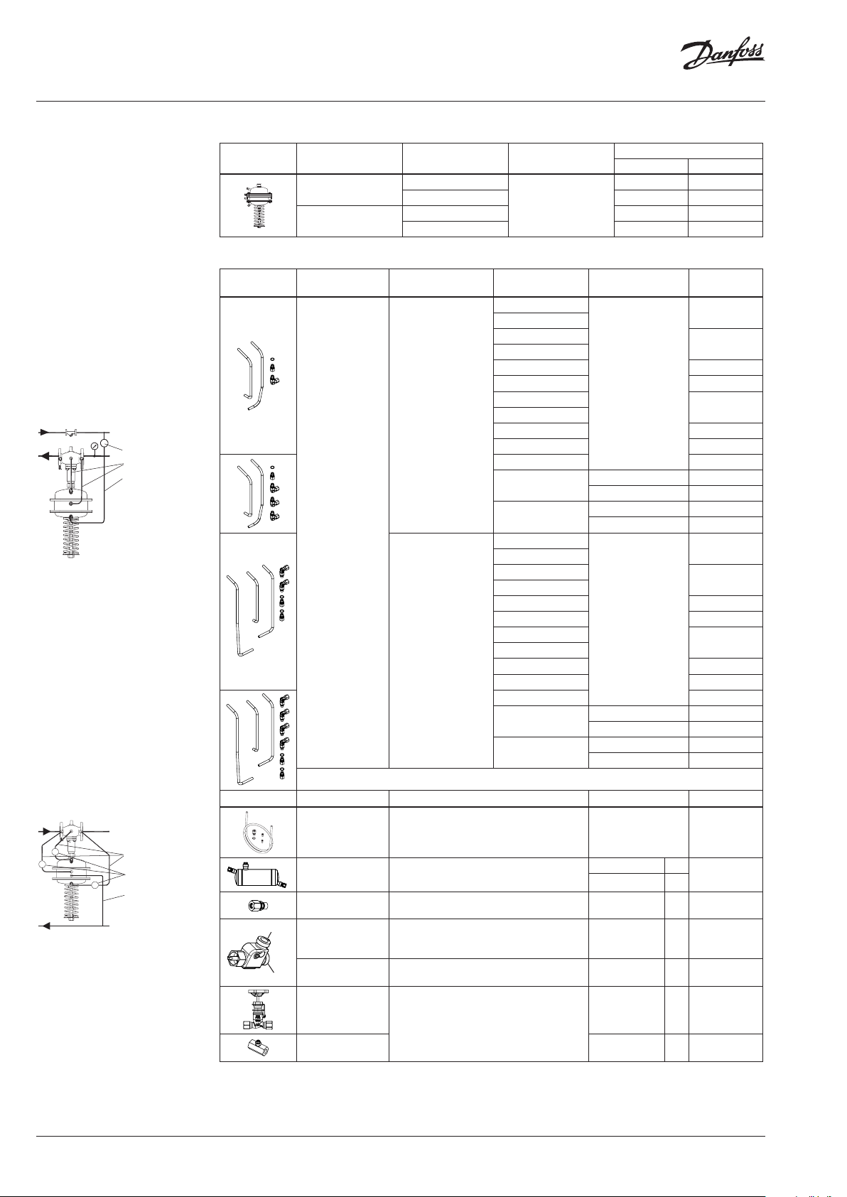
VFQ 2 Valves (metallic sealing cone)
Picture
1)
At temperature s above 150 °C only with seal p ots (see Accessories)
DN
(mm)
15 4.0
20 6.3 065B2655 065B2668 065B2678
25 8.0 065B2656 065B2669 065B2679
32 16 065B2657 065B2670 065B2680
40 20 065B2658 065B2671 065B2681
50 32 065B2659 065B2672 065B2682
65 50 065B2660 065B2673 065B2683
80 80 065B2661 065B2674 065B2684
100 125 065B2662 065B2675 065B2685
125 160 065B2663 065B2676 065B2686
150 280
200 320 065 B2758 – 065B2688
250 400 065B2759 – 065B2689
k
VS
(m3/h)
Connections
Flanges acc. to
EN 1092-1
T
( °C)
150
150
max
Code No.
PN 16 PN 25 PN 40
065B2654
065B2664
T
( °C)
200
150
max
1)
Code No.
065B2667 065B2677
– 065B2687
© Danfoss | 2018.10
VD.CA.A7.02 | 1
Data sheet Differential pressure and flow controller AFPQ (4) / VFQ 2(1) (PN 16, 25, 40)
Ordering (continuous)
Example 2:
Differential pressure and flow
controller; return mounting;
DN 15; kVS 4.0; PN 25; metallic
sealing; setting range 0.1-0.7 bar;
flow restrictor ∆ pb 0.2 bar;
T
200 °C; flange;
max
– 1× VFQ 2 DN 15 valve
Code no: 065B2667
– 1× AFPQ actuator
Code no: 003 G102 9
– 1× AFPQ DN 15 impulse tubes
Code no: 003G1365
– 1× Impulse tube set AF
Code no: 003G1391
– 1× Seal pot V1
Code no: 003G1392
Products will be delivered separatly.
Seal pot V1
Impulse t ubes AFPQ
Impulse tube set AF
Example 3:
Differential pressure and flow
controller; flow mounting; DN 15;
kVS 4.0; PN 25; metallic sealing;
setting range 0.1-0.7 bar; flow
restrictor ∆pb 0.2 bar; T
flange;
– 1× VFQ 2 DN 15 valve
Code no: 065B2667
– 1× AFPQ actuator
Code no: 00G10 33
– 4× Impulse tube set AF
Code no: 003G1391
– 3× Seal pot V1
Code no: 003G1392
Products will be delivered separatly.
200 °C;
max
Impulse tube set AF
Seal pot V1
Impulse tube set AF
AFPQ / AFPQ 4 Actuators
Picture
∆p setting range
(bar)
0.1-0.7
0.15 -1.5
Flow restrictor ∆p
(bar)
0.2
0.5 003G1030 003G1034
0.2 003G1031 003G1035
0.5 003G1032 003G1036
Nominal pressure
b
(PN)
40
AFPQ (retur n) AFPQ 4 (flow)
Code No.
003 G1029 003G1033
Accessories
Picture Type designation For controller
AFPQ
Impulse tubes
(Stainless steel)
Picture Type designation Description Ordering number Code No.
Impulse tube set AF
Seal pot V1
Compression
fitting
port B
Combination piece
KF3
port A
4)
Combination piece
KF2
3)
AFPQ 4
– 1× Copper tube Ø10 × 1 × 1500 mm
– 1 × compression fitting for imp. tube
connection to pipe (G ⁄)
– 2 × socket
1)
2)
Capacit y 1 liter; with compression fittings for
imp. tube Ø10
For impulse tube Ø10 connections to
controller
For combination with pressure actuators.
Electrical actuator connected on side (port B)
only for ON/OFF function
For combination with thermostat - side
connection to port B
DN
(mm)
15
20
25
32
40 003G1369
50 0 03G1370
65
80
100 00 3G1373
125 0 03G1374
150 0 03G1375
200
250
15
20
25
32
40 00 3G1382
50 003G1383
65
80
100 003 G1386
125 0 03G1387
150 00 3G1388
200
250
PN Code No.
16, 25, 40
16 00 3G1416
40 00 3G1376
16 00 3G1417
40 003 G1405
16, 25, 40
16 00 3G1418
40 003 G1389
16 00 3G1419
40 003 G1406
– 003G1391
AFPQ 1×
AFPQ 4 3×
G ⁄ 003G1468
G 1⁄ / 2× G 1⁄ 00 3G1441
00 3G1365
00 3G1367
00 3G1371
00 3G1378
00 3G1380
00 3G1384
003G1392
00 3G1440
2 | © Danfoss | 2018.10
Shut off valve
Throttle valve 065B2909
1)
Seal pot has to be use d on impulse tubes always wh en T
2)
Consist of a nipple, com pression ring and nut
3)
With combination pi ece KF2 or KF3 use 2× 003G1391 at PN 16 and T<150 °C. Other wise impulse tubes on speci al request.
4)
Port A - for connect ion of any type of actu ator
For impulse tube Ø10
≥ 150 °C
max
– 00 3G1401
VD.CA.A7.02
Data sheet Differential pressure and flow controller AFPQ (4) / VFQ 2(1) (PN 16, 25, 40)
Ordering (continuous)
Technical data
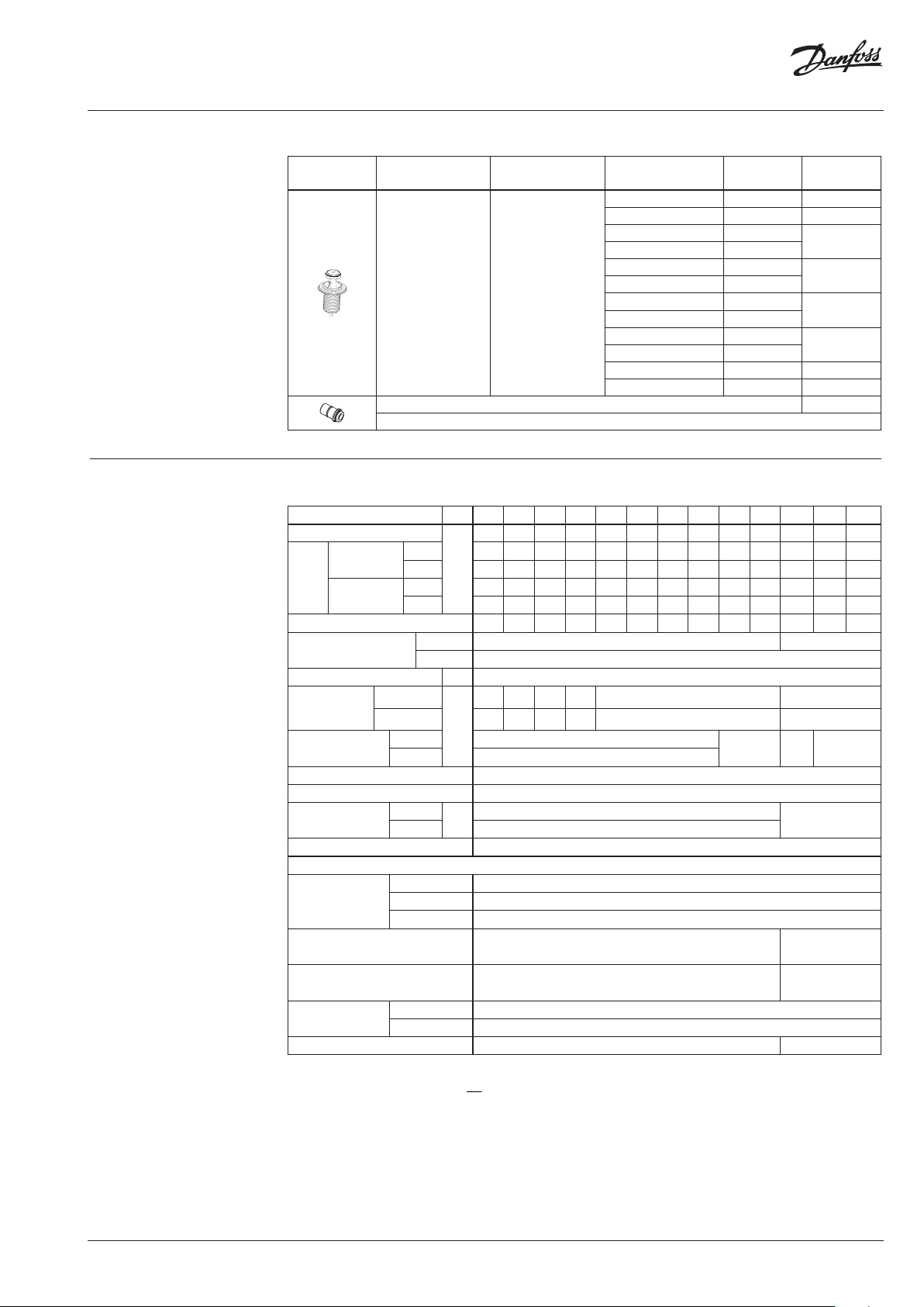
Service kits
Picture Type designation For valve
Valve insert VFQ 2
Stuffing cone (with EPDM O-rings) 003G1464
DN
(mm)
15 4.0 065B2796
20 6.3 065B2797
25 8
32 16
40 20
50 32
65 50
80 80
100 125
125 160
150 280 065B2964
250 400 065B2965
k
VS
(m3/h)
Code No.
065B2798
065B2799
065B2800
065B2801
Valve
Nominal diameter DN 15 20 25 32 40 50 65 80 100 125 150 200 250
kVS value of p controller
Range
of
max.
flow
setting
pb 1) = 0.2 bar
pb 1) = 0.5 bar
from 0.1 0.2 0.2 0.4 0.6 0.8 3 4 6 8 12 15 18
to 2 3 4 7 11 16 28 40 63 80 125 150 180
from 0.2 0.3 0.3 0.5 0.8 1. 2 4 6 9 12 18 22 25
to 3 4.5 6 10 16 24 40 58 90 120 180 220 250
Cavitation factor z 0.6 0.6 0.6 0.55 0.55 0.5 0.5 0.45 0.4 0.35 0.3 0.2 0.2
Leakage acc. to standard
IEC 534 (% of kVS)
VFQ 2 ≤ 0.03 ≤ 0.05
VFQ 21 ≤ 0.01
Nominal pressure PN 16, 25, 40
Min. differential
pressure for max
2)
flow
Max. differential
pressure
pb 1) = 0.2
pb 1) = 0.5 0.8 0.7 0.8 0.7 0.8 0.7
PN 16 16
PN 25, 40 20
Media Circulation water / glycolic water up to 30 %
Media pH Min. 7, max. 10
Media temperature
VFQ 2
VFQ 21 2 … 150
Connections Flange
Materials
PN 16 Grey cast iron EN-GJL-250 (GG-25)
Valve body
PN 25 Ductile iron EN-GJS-400(GGG-40.3)
PN 40 Cast steel GP240GH (GS-C 25)
Valve seat Stainless steel, mat. No. 1.4021
Valve cone Stainless steel, mat. No. 1.4404
Sealing
VFQ 2 Metal
VFQ 21 EPDM
Pressure relieve system Bellows (Stainless steel, mat. No. 1.4571) Diaphragm (EPDM)
1)
∆pb – differe ntial pressure over flow restri ctor
2)
For flows smal ler than Q
3)
at temperatures ab ove 150 °C only with seal pot s (see Accessories)
->
max
4.0 6.3 8.0 16 20 32 50 80 125 160 280 320 400
m3/h
0.5 0.4 0.5 0.4 0.5 0.4
bar
15 12 10
°C
2
Q
p
p
min
b
k
VS
2 … 150/2 … 200
3)
2 … 150
Stainless steel,
mat. No. 1.4313
Stainless steel,
mat . No. 1.4021
VD.CA.A7.02
© Danfoss | 2018.10 | 3
Data sheet Differential pressure and flow controller AFPQ (4) / VFQ 2(1) (PN 16, 25, 40)
Technical data (continuous)
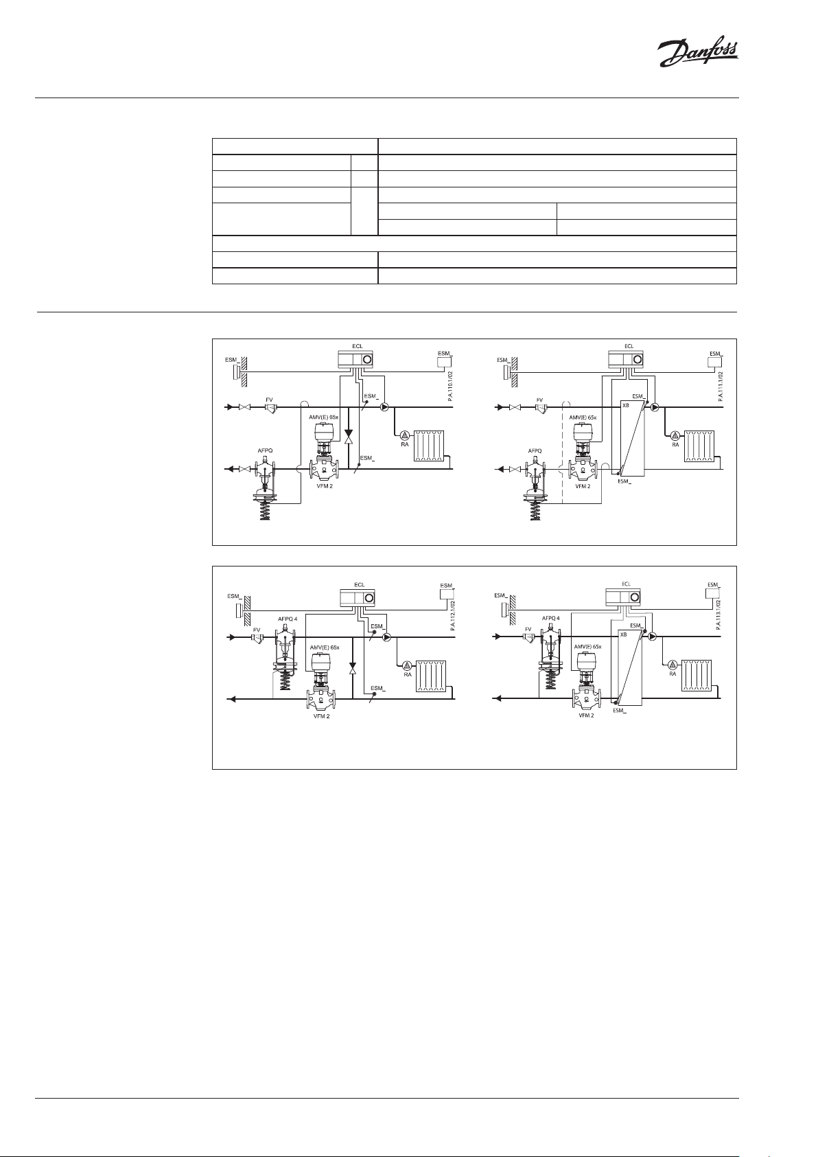
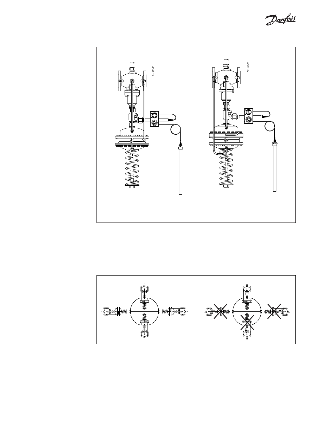
Application principles
– Return mounting
Actuator
Typ e AFPQ, AFPQ 4
Actuator size cm
Nominal pressure PN 40
Flow restrictor dif f. pressure p
Diff. pressure setting ranges
and spring colours
Materials
Actuator housing Steel, mat. No.1.0338, zinc plated
Control diaphragm EPDM (Rolling; fibre enforced)
2
b
bar
0.1-0.7 0.15 -1.5
yellow red
250
0.2 / 0.5
– Flow mounting
Direct-connected heating system Indirectly connected heating system
Direct-connected heating system Indirectly connected heating system
4 | © Danfoss | 2018.10
VD.CA.A7.02
Data sheet Differential pressure and flow controller AFPQ (4) / VFQ 2(1) (PN 16, 25, 40)
Combinations
Example:
Differential pressure, flow and
temperature controller, return
mounting; DN 15; kVS 4.0; PN 16;
metallic sealing; setting range
0.1-0.7 bar; flow restrictor
∆pb 0.2 bar; T
– 1× VFQ 2 DN 15 valve
Code no: 065B2654
– 1× AFPQ actuator
Code no: 003G1029
– 3× Impulse tube set AF
Code no: 003G1391
– 1× AFT06 thermostat
Code no: 065-4390
– 1× Combination piece KF2
Code no: 003G1398
Products will be delievered
separatelly.
Note:
For AFT 06 thermostat data see
relevant data sheet
150 °C; flange;
max
AFT 06 / KF2 / AFPQ / VFQ2
– Differential pressure, flow and temperature controller,
return mounting
Installation positions DN 15-80 T
The controllers can be installed in any position.
DN 15-80 T
≤ 120 °C
max
≤ 120 °C
max
AFT 06 / KF2 / AFPQ 4 / VFQ2
– Differential pressure, flow and temperature controller,
flow mounting
DN 15-80 T
> 120 °C; DN 100-250
max
The controllers can be installed in horizontal
pipes only, with a pressure actuator oriented
downwards.
DN 15-80 T
> 120 °C; DN 100-250
max
VD.CA.A7.02
© Danfoss | 2018.10 | 5
Data sheet Differential pressure and flow controller AFPQ (4) / VFQ 2(1) (PN 16, 25, 40)
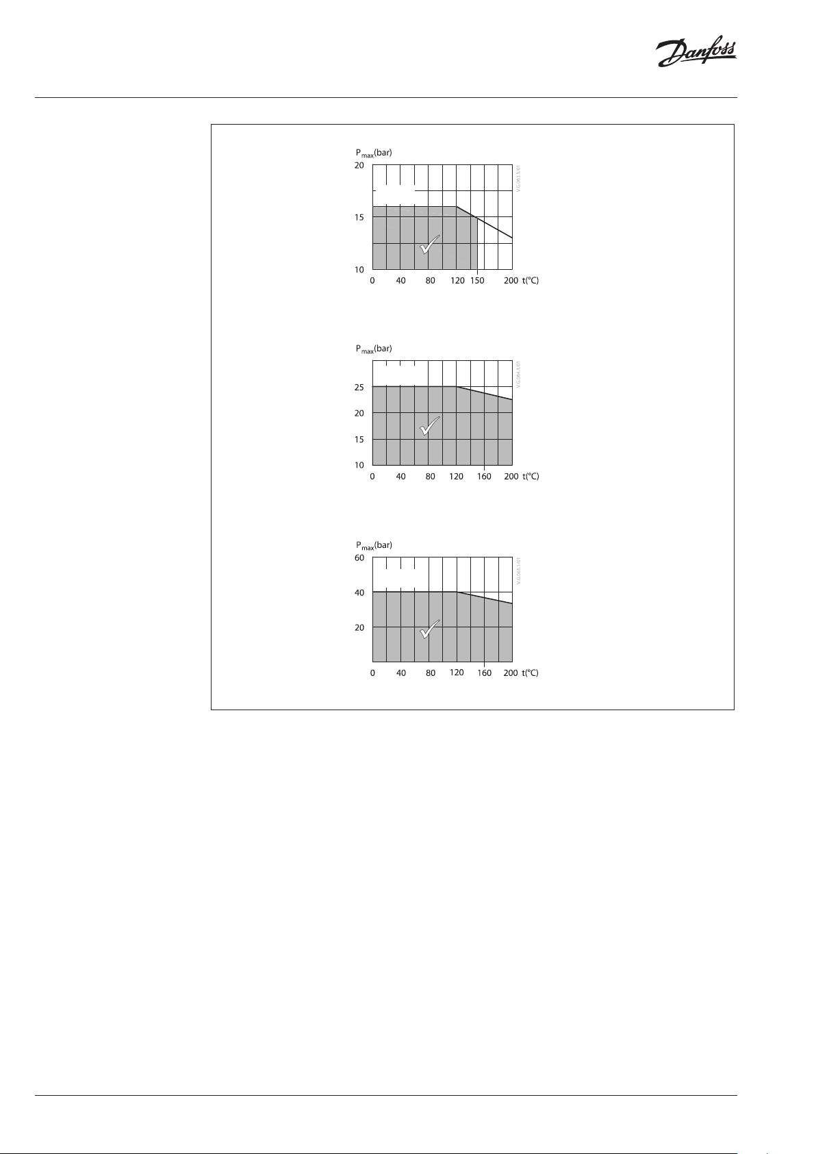
Pressure temperature
diagram
Working area is below P-T line
and it ends at Tmax for each
valve
Maximum allowed operating pressure as a function of media temperature (according to EN 1092-2)
PN 16
EN - GJL- 250
(GG -25)
PN 25
EN-GJS- 400
(GGG-40.3)
Maximum allowed operating pressure as a function of media temperature (according to EN 1092-2)
PN 40
EN-GP-240-GH
(GS- C 25)
Maximum allowed operating pressure as a function of media temperature (according to EN 1092-1)
6 | © Danfoss | 2018.10
VD.CA.A7.02
Data sheet Differential pressure and flow controller AFPQ (4) / VFQ 2(1) (PN 16, 25, 40)
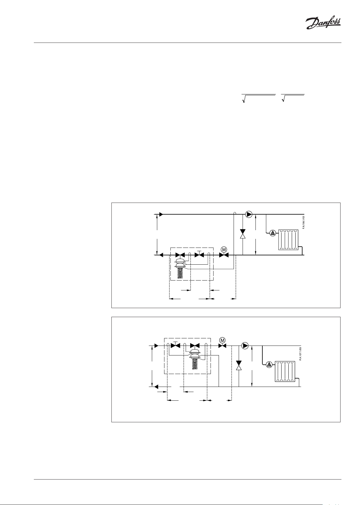
Sizing
– Directly connected heating
system
Example 1
Motorised control valve (MCV) for mixing circuit
in direct-connected heating system requires
differential pressure of 0.3 bar (30 kPa) and flow
less than 1.900 l/h.
Given data:
Q
= 1.9 m3/h (1.900 l/h)
max
p
= 0.9 bar (90 kPa)
min
1)
p
= 0.1 bar (10 kPa)
circuit
p
= 0.3 bar (30 kPa) selected
MCV
2)
p
= 0.2 bar (20 kPa)
b
Remark:
1)
∆p
corresponds to the r equired pump pressure in t he heating
circuit
circuit and is not to b e considered when sizing the AFPQ (4).
2)
pb is differe ntial pressure over flow restri ctor.
The differential pressure set value is:
p
p
= p
set value
= 0.3 bar (30 kPa)
set value
MCV
The total pressure loss across the controller is:
p
= p
AFPQ
p
= 0.6 bar (60 kPa)
AFPQ
min
− p
= 0.9 – 0.3
MCV
Q
max
Possible pipe pressure losses in tubes, shut-off
fittings, heatmeters, etc. are not included.
kv value is calculated according to formula:
Q
k
v
max
pp
bAFPQ
9,1
2,06,0
kv = 3.0 m3/h
Solution:
The example selects AFPQ 4 DN 15, kVS value 4.0,
with differential pressure setting range 0.1-0.7 bar
flow setting range 0.1-2.0 m3/h.
,
∆p
∆p
min
∆p
∆p
circuit
circuit
min
AFPQ
∆p
b
∆p
AFPQ
AFPQ 4
Q
max
∆p
b
∆p
AFPQ
∆p
∆p
MCV
MCV
VD.CA.A7.02
© Danfoss | 2018.10 | 7
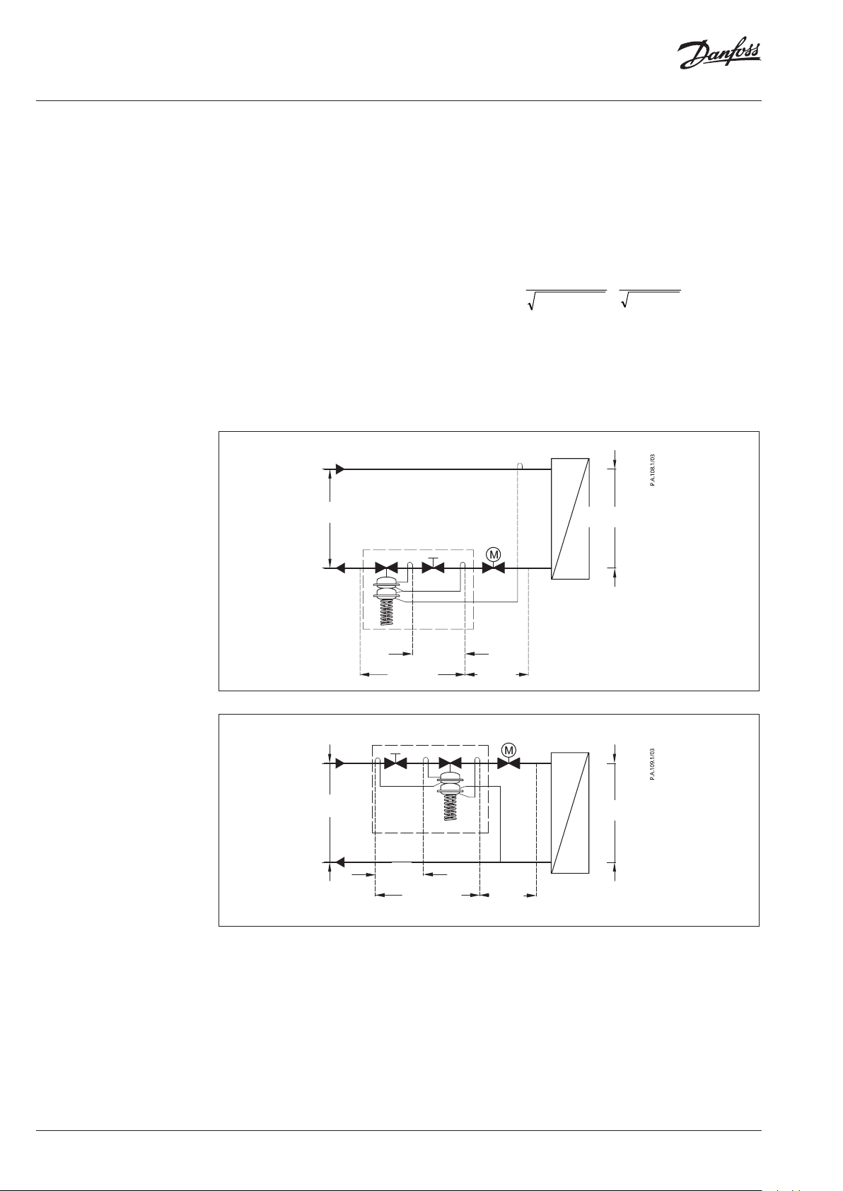
Data sheet Differential pressure and flow controller AFPQ (4) / VFQ 2(1) (PN 16, 25, 40)
Sizing (continuous)
– Indirectly connected heating
system
Example 2
Motorised control valve (MCV) for indirectly
connected heating system requires differential
pressure of 0.3 (30 kPa) bar and flow less than
1.800 l/h.
Given data:
Q
= 1.8 m3/h (1.800 l/h)
max
p
= 1.0 bar (100 kPa)
min
p
p
p
Remark:
1)
pb is differe ntial pressure over flow restri ctor
= 0.05 bar (5 kPa)
exchanger
= 0.3 bar (30 kPa) selected
MCV
1)
= 0.2 bar (20 kPa)
b
The differential pressure set value is:
p
= p
set value
p
= 0.05 + 0.3
set value
p
= 0.35 bar (35 kPa)
set value
exchanger
+ p
∆p
min
MCV
Q
max
AFPQ
The total pressure loss across the controller is:
p
= p
AFPQ
p
= 1.0 − 0.05 − 0.3
AFPQ
p
= 0.65 bar (65 kPa)
AFPQ
min
− p
exchanger
− p
MCV
Possible pipe pressure losses in tubes, shut-off
fittings, heatmeters, etc. are not included.
kv value is calculated according to formula:
Q
k
v
max
pp
bAFPQ
8,1
2,065,0
kv = 2.7 m3/h
Solution:
The example selects AFPQ 4 DN 15, kVS value 4.0,
with differential pressure setting range
0.1-0.7 bar, flow setting range 0.1-2.0 m3/h.
∆p
exchanger
∆p
∆p
b
∆p
AFPQ
AFPQ 4
Q
max
min
∆p
b
∆p
AFPQ
∆p
∆p
MCV
MCV
∆p
exchanger
8 | © Danfoss | 2018.10
VD.CA.A7.02

Data sheet Differential pressure and flow controller AFPQ (4) / VFQ 2(1) (PN 16, 25, 40)
17
21
18
14
11
13
12
22
15
16
3
17
21
18
14
11
13
22
12
15
16
Design
1. Valve body
2. Cover
3. Adjustable flow restrictor
4. Valve seat
5. Valve insert
6. Pressure relieved valve cone
7. Valve stem
8. Bellows for pressure relief of
valve cone
9. Diaphragm for pressure relief
of valve cone
10. Actuator
11. Control diaphragm for flow
control
12. Control diaphragm for diff.
pressure control
13. Excess pressure safety valve
14. Built-in spring for flow
control
15. Setting spring for diff.
pressure control
16. Adjuster for diff. pressure
setting, prepared for sealing
17. Stuffing cone
18. Union nut
19. Impulse tube
20. Compression fitting for
impulse tube
21. Upper casing of diaphragm
22. Lower casing of diaphragm
23. Valve body extension
24. Shut off valve for water filling
25. Closing plug
19
10
20
20
AFPQ VFQ 2(1), DN 15-125
3
1
4
6
7
19
5
8
2
10
20
AFPQ 4 VFQ 2(1), DN 15-125
1
4
6
7
5
8
2
9 2
VFQ 2(1) DN 150-250, T
25
24
max
150 °C
23
9
2
Function
Setting
Flow volume causes pressure drop across the
adjustable flow restrictor. Resulting pressures
are being transferred through the impulse tubes
to the actuator chambers and act on control
diaphragm for flow control. The flow restrictor
diff. pressure is controlled and limited by means
of built-in spring for flow control. Control valve
closes on rising differential pressure and opens
on falling differential pressure to control max
flow.
Flow setting
Flow setting is being done by the adjustment of
the flow restrictor position. The adjustment can
be performed on the basis of flow adjustment
diagram (see relevant instructions) and/or by the
means of heat meter.
VFQ 2 DN 150-250, T
max
200 °C
Pressure changes from flow and return pipes are
being transferred through the impulse tubes
to the actuator chambers and act on control
diaphragm for diff. pressure control. The diff.
pressure is controlled by means of setting spring
for diff. pressure control. Control valve closes
on rising differential pressure and opens on
falling differential pressure to maintain constant
differential pressure.
Controller is equipped with two excess pressure
safety valves, which protect control diaphragms
for flow and diff. pressure control from too high
differential pressure.
Differential pressure setting
Differential pressure setting is being done by the
adjustment of the setting spring for diff. pressure
control. The adjustment can be done by means
of adjuster for diff. pressure setting and pressure
indicators.
VD.CA.A7.02
© Danfoss | 2018.10 | 9

Data sheet Differential pressure and flow controller AFPQ (4) / VFQ 2(1) (PN 16, 25, 40)
ø89
Dimensions
L
2
B
3
H
B
B
L
VFQ DN 15-125
L
2
B
H
B
1
H
1
B
VFQ DN 150-250
VFQ DN 150-250
with valve body extension up to 200 °C
VFQ 2, VFQ 21 Valves
DN 15 20 25 32 40 50 65 80 100 125 150 200 250
L
B 213 213 239 239 241 241 276 276 381 3 81 326 354 401
B
2
H 337 337 374 374 393 393 440 440 575 575 595 686 756
PN 16 / 25
Weight
PN 40 31 34 63 72 147 264 347
B
1
B
3
H
1
Weight (valve
with body
extension)
PN 16 / 25
PN 40 187 350 526
130 150 160 180 200 230 290 310 350 400 480 600 730
mm
124 124 135 13 5 152 152 164 16 4 194 19 4 269 332 355
kg 8 9 10.5 12 .5 15. 5 18.5
mm
kg
28.5 31 61 71 120 193 337
620 852 119 9
269 332 356
889 1184 1555
160 314 489
ø60
AFPQ, AFPQ 4 Actuators
Actuator type AFPQ / AFPQ 4
Ø A
H for xs = 0.1-0.7 / 0.15-1.5 520/540
Weight kg 34
mm
257
SW 22
Shut off valve
Ø10
110
78
10 | © Danfoss | 2018.10
240
Seal pot V1
Comb. piece KF2, KF3
40
G⁄
SW19
Compression fitting
VD.CA.A7.02

Data sheet Differential pressure and flow controller AFPQ (4) / VFQ 2(1) (PN 16, 25, 40)
VD.CA.A7.02
© Danfoss | 2018.10 | 11

Data sheet Differential pressure and flow controller AFPQ (4) / VFQ 2(1) (PN 16, 25, 40)
12 | © Danfoss | DHS-SRMT/SI | 2018.10
VD.CA.A7.02
 Loading...