

Page 1
Data sheet
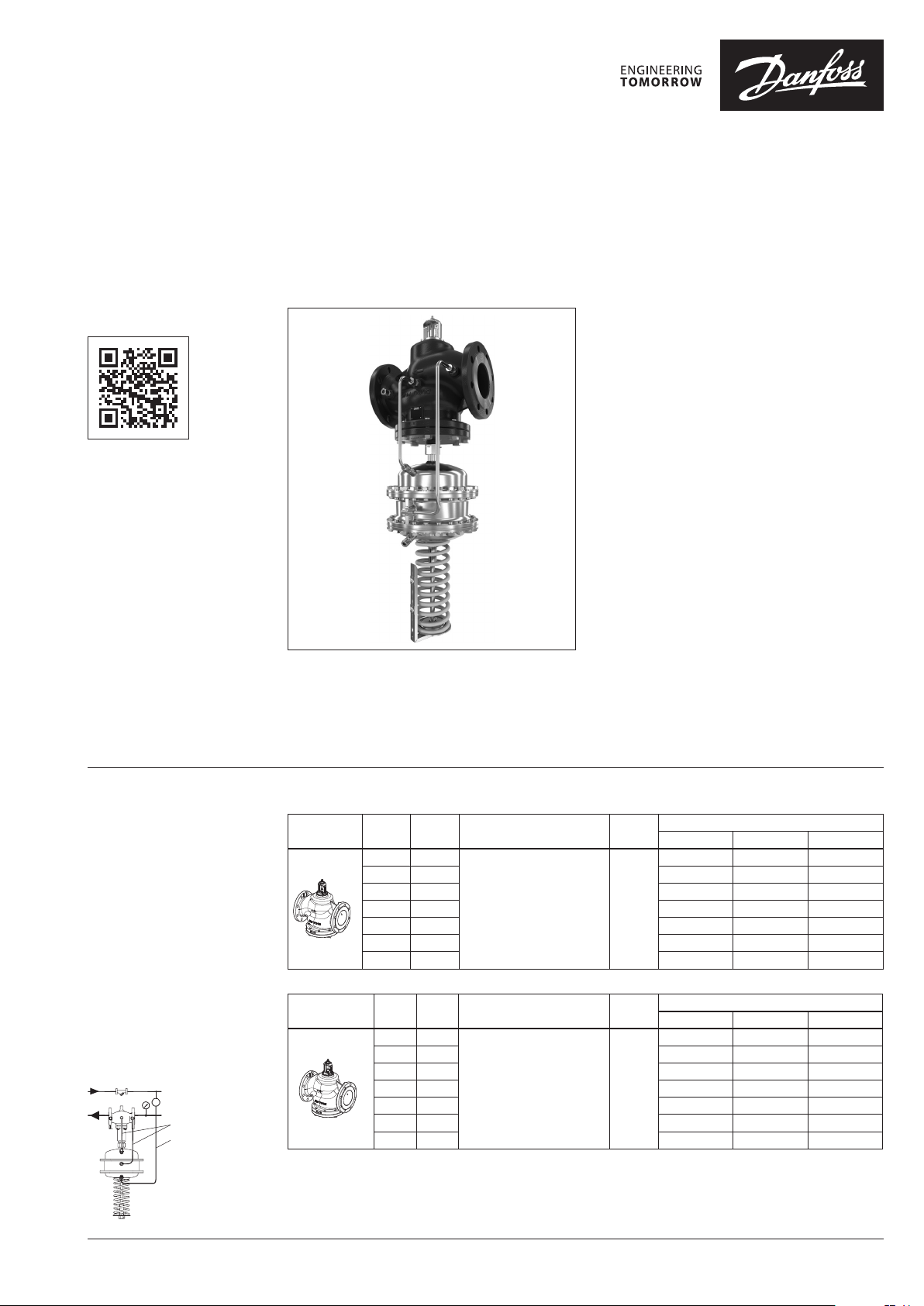
Differential pressure and flow controller (PN 16, 25, 40)
AFPQ 2 / VFQ 22(1) – return mounting, adjustable setting
AFPQ 24 / VFQ 22(1) – flow mounting, adjustable setting
Description
virtus.danfoss.com
The controller is a self-acting differential pressure
and flow controller primarily for use in district
heating systems. Direct operated, reliable and
high precise controller closes on rising differential
pressure or when set max. flow is exceeded.
The controller has a control valve with adjustable
flow restrictor, an actuator with two control
diaphragms and spring for differential pressure
setting. Differential pressure control and flow
control are independent.
Further on two valve versions are available:
∙ VFQ 22 with metallic sealing cone
∙ VFQ 221 with soft sealing cone
Together with Danfoss intelligent electrical
actuator AMEi 6 intelligent optimization
functions are available:
∙ iSET-intelligent substation efficiency
optimization
∙ iNET-intelligent network balancing
Main data:
∙ DN 65-250
∙ kVS 60-800 m3/h
∙ Flow range 5.6-500 m3/h
∙ PN 16, 25, 40
∙ Setting range: 0.2-1 bar / 0.5-1.5 bar
∙ Flow restrictor ∆pb: 0.2 bar or 0.5 bar
∙ Temperature: – Circulation water / glycolic
water up to 30%: 2 … 150°C
∙ Connections: – Flange
Ordering
Example 1:
Differential pressure controller,
return mounting, DN 65, kVS 60,
PN 16, metallic sealing, setting
range 0.5-1.5 bar, flow restrictor
Δpb 0.2 bar, T
– 1× VFQ 22 DN 65 valve
Code no: 065B 5570
– 1× AFPQ 2 actuator
Code no: 00 3G 5712
– 1×
Code no: 003G1838
– 1× Impulse tube set AF
Code no: 003G1391
Products will be delivered
separately.
150 °C, flange
max
AFPQ 2 DN 65 impulse tube set
AFPQ 2 impuls e tube set
Impulse t ube set AF
VFQ 22 Valve (metallic sealing cone)
Picture
DN
(mm)
65 60
80 80 065B5571 065B5578 065B5585
100 160 065B5572 065B5579 065B5586
125 250 065B5573 065B5580 065B5587
150 380 065B5574 065B5581 0 65B5588
200 650 065B5575 065B5582 065B5589
250 800 06 5B5576 065B5583 065B5590
k
VS
(m3/h)
Flanges acc. to EN 1092-1 150
VFQ 221 Valve (soft sealing cone)
DN
k
Picture
1)
PN40 available Q1 2022
(mm)
100 160 065B5602 065B5609 065B5616
125 250 065B5603 065B5610 0 65B 5617
150 380 065B5604 06 5B5 611 065B5618
200 650 065B5605 065B5612 0 65B5 619
250 800 065B5606 06 5B5613 065B5620
VS
(m3/h)
65 60
80 80 065B5601 065B5608 065 B5615
Flanges acc. to EN 1092-1 150
Connections
Connections
T
(°C)
T
(°C)
max.
max.
PN 16 PN 25 PN 40
065B5570 065B5577 065B5584
PN 16 PN 25 PN 40
065B5600 065B5607 06 5B5614
Code No.
Code No.
1)
1)
© Danfoss | 2022.03 AI388353838246en-010203 | 1
Page 2
Data sheet AFPQ 2, AFPQ 24 / VFQ 22(1)
Ordering (continuous) AFPQ 2 / AFPQ 24 Actuators
Picture
Actuator size
(cm3)
160*
320
* avaliable from Q4/2022
Acessories - Impulse tube set
Picture
AFPQ 2 (return)
* avaliable from Q4/2022
Picture
AFPQ 24 (flow)
Accessories
Picture Type designation Description Connections Code No.
Impulse tube set AF
Compression fitting
Δp setting range
(bar)
0.2 - 1
0.5 - 1.5
0.2 - 1
0.5 - 1.5
Actuator size
(cm2)
160*
1)
Flow restrictor Δpb
(bar)
0.2
0.5 00 3G5 711 003G 5719
0.2 003 G5712 003G5720
0.5 003 G5713 0 03G5721
0.2
0.5 003 G5715 003G 5723
0.2 003G 5716 003G5724
0.5 003 G5717 003G5725
Valve
(DN)
65 0 03G1838 003G1839
80 00 3G1844 003G18 47
100 003G1845 003G1848
125 003G1846 003G18 49
65 0 03G184 0 003G18 41
80 003G186 2 003G18 68
100 003G1863 003G1869
320
125 003G18 64 00 3G1870
150 003G18 65 003G1871
200 003 G1866 0 03G1872
250 003G1867 003G1873
– 1× Copper tube Ø10 × 1 × 1500 mm
– 1× compression fitting for imp.
tube connection to pipe (G ⁄)
– 2× socket
For impulse tube Ø10 connections
to controller
for DN
AFPQ 2 (ret urn) AFPQ 24 (flow)
Code No.
003 G5710 003 G5718
65 -125
00 3G5714 0 03G5722
150-250
Code No.
AFPQ 2 (ret urn) AFPQ 24 (flow)
– 003G1391
G⁄ 003G1468
Shut off valve
Static throt tle valve 065B2909
Dynamic throttle valve
Adapter new AFP 2old VFG DN 15-2 50 0 03G17 80
AMEi 6 iSET
el actuator 230 V
AMEi 6
iSET
el actuator 24 V
AMEi 6 iNET
el actuator 230 V
AMEi 6 iNET
el actuator 24 V
1)
Consist of a nipple , compression ring and nut
2)
Available in 2022
For impulse tube Ø10 –
00 3G1401
2)
For impulse tube Ø10 /
connection to pressure actuator
Intelligent ∆p actuator with iSET
function
Intelligent ∆p actuator with iNET
function
G⁄ 0 03G17 71
082G4300
082G4301
082G4302
082G4303
2 | AI388353838246en-010203 © Danfoss | 2022.03
Page 3
Data sheet AFPQ 2, AFPQ 24 / VFQ 22(1)
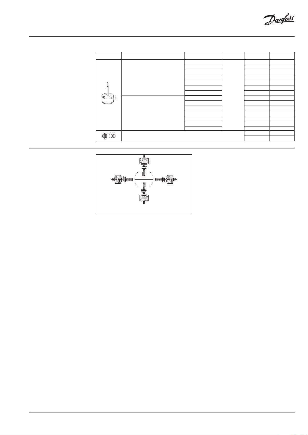
Installation position
Service kits
Picture Typ e
Pressure control
insert VFG/Q 22
Pressure control
insert VFG/Q 221
Pressure stuffing box VFG/Q 221
k
VS
(m3/h)
60
80 80 003 G1801
160 100 003 G1802
250 125 003G1803
380 150 003G18 04
650 200 0 03G1805
800 250 00 3G1806
60 65 00 3G1807
80 80 003G1808
160 100 003 G1809
250 125 003G1810
380 150 00 3G18 11
650 200 003 G1812
800 250 0 03G1813
PN DN Code No.
65 003G1800
16/2 5/40
65 -125 00 3G1730
150-250 00 3G1731
The controllers can be installed in any position.
AI388353838246en-010203 | 3© Danfoss | 2022.03
Page 4

Data sheet AFPQ 2, AFPQ 24 / VFQ 22(1)
p
at z = 0,2 ... 0,6 [bar]
Inlet pressure bar p [bar]
z =
Example :
Technical data
VFQ 22(1) Valve
Nominal diameter DN 65 80 100 125 150 200 250
kVS value of ∆p controller
Range of max. flow
setting
∆pb 1) = 0.2 bar
∆pb 1) = 0.5 bar
from 5.6 8 12.6 20 32 54 72
to 28 40 63 100 160 270 360
from 8.4 12 19 30 48 68 100
to 42 60 95 150 240 340 500
60 80 160 250 380 650 800
m3/h
Cavitation factor z 0.65 0.55 0.4 0.4 0.4 0.35 0.3
Leakage acc. to standard
IEC 534 (% of kVS)
VFQ 22 ≤ 0.03 ≤ 0.05
VFQ 221 ≤ 0.01
Nominal pressure PN 16, 25, 40
Min. differential pressure
Max. dif ferential pressure PN 16 16
bar
Max. dif ferential pressure PN 25/40 20
see remark
15 15 12 10 10
2)
Pressure relieve system Chamber relieved
Media Circulation water / glycolic water up to 30%
Media pH Min. 7, max. 10
Media temperature °C 2 … 150
Connections Flange
Materials
PN 16 Grey cast iron EN-GJL-250 (GG-25)
Valve body
PN 25 Ductile iron EN-GJS-400(GGG-40.3)
PN 40 Cast steel GP240GH (GS-C 25)
Valve seat / Valve cone Stainless steel, mat. No. 1.4021
Sealing EPDM
1)
Δpb – differe ntial pressure over flow restri ctor
2)
For flows smal ler than Q
maks.
->
p
Q
min
k
VS
2
p
b
AFPQ 2(4) Actuator
bar
2
160 320
0.2 / 0.5
0. 2-1 0.5-1.5 0.2-1 0.5-1.5
blue yellow orange red
Materials
Actuator size cm
Max. operating pressure bar 40
Flow restrictor differential pressure ∆pb
Diff. pressure setting ranges and spring
colours
For valve DN 65 -125 65-250
Actuator housing Steel, mat. No. 1.0345, zinc plated
Control diaphragm EPDM (Rolling; fibre enforced)
Impulse tube set AFPQ 2(4) Stainless steel, mat. No. 1.4571
Operating area
Maximum allowed differential pressure over the controller (∆p
max
T = 100°C
T = 110°C
[bar]
max
) at different cavitation factors (z)
max
T = 80°C
T = 90°C
T = 140°C
T = 150°C
p = 6 bar
T = 140°C
z = 0,4
= 1,35 bar
p
max
T = 130°C
p
4 | AI388353838246en-010203 © Danfoss | 2022.03
Page 5

Data sheet AFPQ 2, AFPQ 24 / VFQ 22(1)
Application principles
– Return mounting
Direct-connected heating system Indirectly connected heating system
– Flow mounting
Pressure temperature
diagram
Working area is below P-T line and it
ends at T
for each valve
max
Direct-connected heating system
Indirectly connected heating system
PN 25
PN 16
EN - GJL- 250
(GG -25)
150
150
Maximum allowed operating pressure as a function of media temperature (according to EN 1092-2)
PN 40
EN-GP-240-GH
(GS- C 25)
EN-GJS- 400
(GGG-40.3)
150
Maximum allowed operating pressure as a function of media temperature (according to EN 1092-1)
AI388353838246en-010203 | 5© Danfoss | 2022.03
Page 6

Data sheet AFPQ 2, AFPQ 24 / VFQ 22(1)
pp
Sizing
– Directly connected heating
system
Example 1
Motorised control valve (MCV) for mixing circuit
in direct-connected heating system requires
differential pressure of 0.5 bar (50 kPa) and flow
less than 25.000 l/h.
Given data:
Q
= 25 m3/h (25.000 l/h)
max
p
= 1 bar (100 kPa)
min
1)
p
= 0.1 bar (10 kPa)
circuit
p
= 0.5 bar (50 kPa) selected
MCV
2)
p
= 0.2 bar (20 kPa)
b
Remark:
1)
∆p
corresponds to the r equired pump pressure in t he heating
circuit
circuit and is not to b e considered when sizing the AFPQ (4).
2)
pb is differe ntial pressure over flow restri ctor.
The differential pressure set value is:
p
p
= p
set value
set value
MCV
= 0.5 bar (50 kPa)
The total pressure loss across the controller is:
p
= p
AFPQ
p
= 0.5 bar (50 kPa)
AFPQ
min
− p
= 1 – 0.5
MCV
Q
max
Possible pipe pressure losses in tubes, shut-off
fittings, heatmeters, etc. are not included.
kv value is calculated according to formula:
Q
k
v
max
25
bAFPQ
2.00.5
kv = 45.6 m3/h
Solution:
The example selects AFPQ 2 (return mounting)
or AFPQ 24 (flow mounting) DN 65, kVS value 60,
with differential pressure setting range 0.2-1 bar,
flow setting range 5.6-28 m3/h.
∆p
∆p
min
AFPQ 2
∆p
b
∆p
AFPQ
AFPQ 24
Q
max
min
∆p
b
∆p
AFPQ
∆p
∆p
MCV
MCV
∆p
∆p
circuit
circuit
6 | AI388353838246en-010203 © Danfoss | 2022.03
Page 7

Data sheet AFPQ 2, AFPQ 24 / VFQ 22(1)
pp
Sizing (continuous)
– Indirectly connected heating
system
Example 2
Motorised control valve (MCV) for indirectly
connected heating system requires differential
pressure of 0.5 (50 kPa) bar and flow less than
24.000 l/h.
Given data:
Q
= 24 m3/h (24.000 l/h)
max
p
= 1.0 bar (100 kPa)
min
p
p
p
Remark:
1)
pb is differe ntial pressure over flow restri ctor
= 0.1 bar (10 kPa)
exchanger
= 0.5 bar (50 kPa) selected
MCV
1)
= 0.2 bar (20 kPa)
b
The differential pressure set value is:
p
= p
set value
p
= 0.1 + 0.5
set value
p
= 0.6 bar (60 kPa)
set value
exchanger
+ p
∆p
min
MCV
Q
max
AFPQ 2
The total pressure loss across the controller is:
p
= p
AFPQ
p
= 1.0 − 0.1 − 0.5
AFPQ
p
= 0.4 bar (40 kPa)
AFPQ
min
− p
exchanger
− p
MCV
Possible pipe pressure losses in tubes, shut-off
fittings, heatmeters, etc. are not included.
kv value is calculated according to formula:
Q
k
v
max
24
bAFPQ
2.00.4
kv = 53.7 m3/h
Solution:
The example selects AFPQ 2 (return mounting)
or AFPQ 24 (flow mounting) DN 65, kVS value 60,
with differential pressure setting range
0.2-1 bar, flow setting range 5.6-28 m3/h.
∆p
exchanger
∆p
∆p
b
∆p
AFPQ
AFPQ 24
Q
max
min
∆p
b
∆p
AFPQ
∆p
∆p
MCV
MCV
∆p
exchanger
AI388353838246en-010203 | 7© Danfoss | 2022.03
Page 8

Data sheet AFPQ 2, AFPQ 24 / VFQ 22(1)
Design
1. Valve body
2. Cover
3. Adjustable flow restrictor
4. Valve seat
5. Valve insert
6. Pressure relieved valve cone
7. Valve stem
8. Stem thread protection
bellow
9. Control diaphragm for flow
control
10. Control diaphragm for diff.
pressure control
11. Excess pressure safety valve
12. Built-in spring for flow
control
13. Setting spring for diff.
pressure control
14. Adjuster for diff. pressure
setting, prepared for sealing
15. Stuffing cone
16. Union nut
17. Impulse tube
18. Compression fitting for
impulse tube
19. Upper casing of diaphragm
20. Lower casing of diaphragm
AFPQ 2 VFQ 22(1), DN 65-250 AFPQ 24 VFQ 22(1), DN 65-250
Function
Flow volume causes pressure drop across the
adjustable flow restrictor. Resulting pressures
are being transferred through the impulse tubes
to the actuator chambers and act on control
diaphragm for flow control. The flow restrictor
diff. pressure is controlled and limited by means
of built-in spring for flow control. Control valve
closes on rising differential pressure and opens
on falling differential pressure to control max
flow.
Settings Differential pressure setting
Differential pressure setting is being done by the
adjustment of the setting spring for diff. pressure
control. This is done by rotating the differential
pressure setting nut. Set differential pressure
should be checked by observing the pressure
indicators.
Pressure changes from flow and return pipes are
being transferred through the impulse tubes
to the actuator chambers and act on control
diaphragm for diff. pressure control. The diff.
pressure is controlled by means of setting spring
for diff. pressure control. Control valve closes
on rising differential pressure and opens on
falling differential pressure to maintain constant
differential pressure.
Controller is equipped with two excess pressure
safety valves, which protect control diaphragms
for flow and diff. pressure control from too high
differential pressure.
Flow setting
Flow setting is being done by the adjustment of
the flow restrictor position. The adjustment can
be performed on the basis of flow adjustment
diagram (see relevant instructions) and/or by the
means of heat meter.
8 | AI388353838246en-010203 © Danfoss | 2022.03
Page 9

Data sheet AFPQ 2, AFPQ 24 / VFQ 22(1)
Dimensions
L
V
H
H
B
VFQ 22(1) DN 65-250
VFQ 22, VFQ 221 Valves
Weight
PN 16 PN 25 PN 40
DN
L B H H
V
mm kg
65 290 237 473 396 28 29 31
80 310 237 473 396 33 34 36
100 350 272 547 472 52 53 57
125 400 268 582 514 71 72 79
150 480 326 670 610 123 12 6 135
200 600 361 773 7 13 230 236 286
250 730 419 843 783 382 392 441
ØA
A
H
AFPQ 2, AFPQ 24 Actuators
Typ e Size ØA HAH
(cm2) mm AFPQ 2(4)
AFPQ 2
AFPQ 24
160 230 630 730 26 29
320 300 630 730 38 41
160 230 650 750 33 36
320 300 650 750 45 48
AI
Weight (kg)
AFPQ 2(4)
+ AMEi 6
Total installation height o f the controller (VFQ 22(1) valve + AFPQ 2
pressure actu ator) is sum of HV and HA (H
)
AI
ØA
AI
H
min. 250
AMEi 6 intellige nt
Ø60
SW 22
110
Ø10
40
G⁄
SW19
actuator with iSE T/ iNET
function ality should be
ordered sepa rately
78
Shut off valve
Compression fitting
© Danfoss | DCS-SGDPT/SI | 2022.039 | AI388353838246en-010203
 Loading...