

Page 1
Data sheet
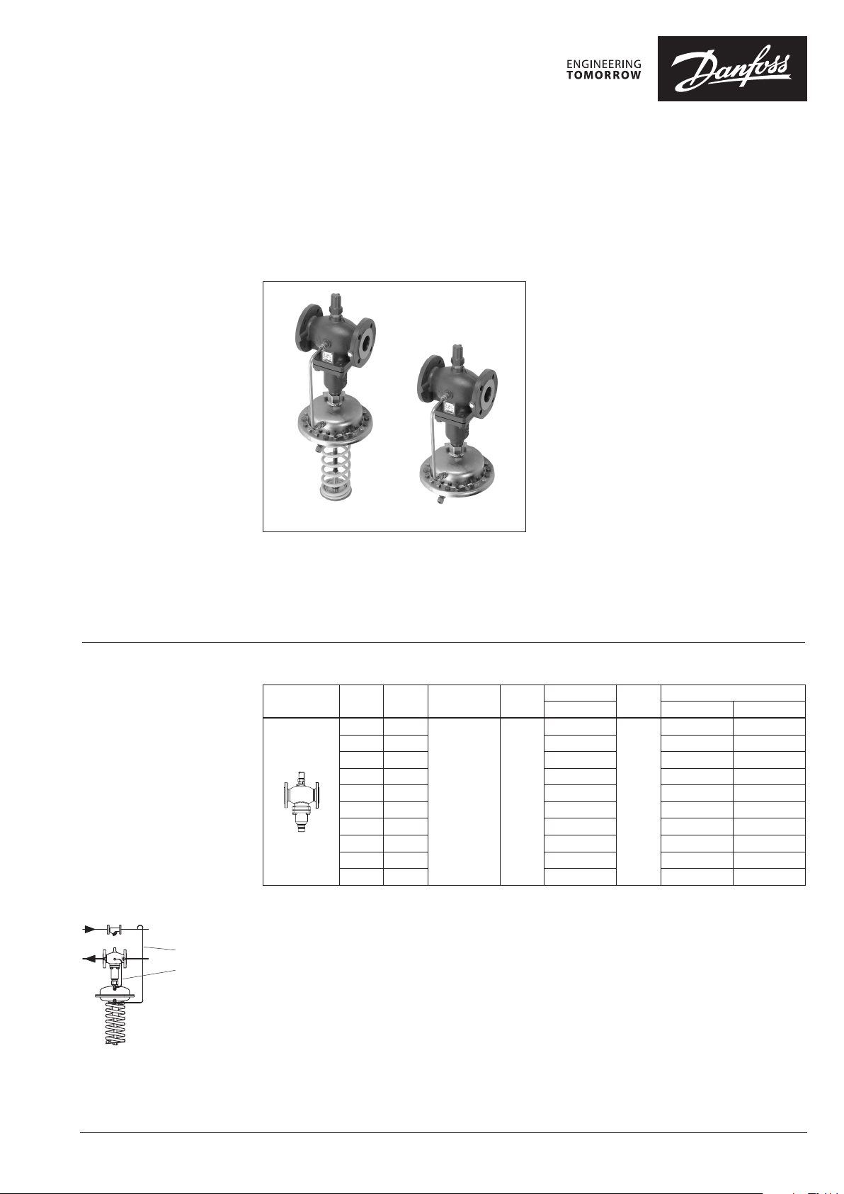
Differential pressure controller with flow limitation (PN 16, 25, 40)
AFPB / VFQ 2(1) – return mounting, adjustable setting
AFPB-F / VFQ 2(1) – return mounting, fixed setting
Description
Ordering
Example 1:
Differential pressure controller with
flow limitation; return mounting;
DN 15; kVS 4.0; PN 16; metallic
sealing; setting range 0.1- 0.7 bar;
t
150 °C; flange;
max
– 1× VFQ 2 DN 15 valve
Code no: 065B2654
– 1× AFPB actuator
Code no: 00 3G1017
– 1× AFPB DN 15 impulse tube
Code no: 003G1355
– 1× Impulse tube set AF
Code no: 003G1391
Products will be delivered separatly.
AFPB AFPB- F
The controller is a self-acting differential pressure
controller with flow limitation primarily for use in
district heating systems. The controller closes on
rising differential pressure or when set max. flow
is exceeded.
VFQ 2 Valves (metallic sealing cone)
Picture
Note: othe r valves available on special r equest.
1)
At temperat ures above 150 °C only with seal pots (see Accessori es)
DN
(mm)
15 4.0
20 6.3 065B2655 065B2668 065B2678
25 8.0 065B2656 065B2669 065B2679
32 16 065B2657 065B2670 065B2680
40 20 065B2658 065B2671 065B2681
50 32 065B2659 065B2672 065B2682
65 50 065B2660 065B2673 065B2683
80 80 065B2661 065B2674 065B2684
100 125 065B2662 065B2675 065B2685
125 160 065B2663 065B2676 065B2686
k
VS
(m3/h)
Connections
Flanges acc. to
EN 1092 -1
T
(°C)
150
The controller has a control valve with adjustable
flow restrictor, an actuator with one control
diaphragm and spring for differential pressure
setting.
Further on two valve versions are available:
– VFQ 2 with metallic sealing cone
– VFQ 21 with soft sealing cone (on special
request)
Main data:
∙ DN 15 -125
∙ kVS 4.0 -160 m3/h
∙ Flow range: 0.05-120 m3/h
∙ PN 16, 25, 40
∙ Setting range: 0.1-07 bar/0.15-1.5 bar
∙ Temperature:
– Circulation water/glycolic water up to 30 %:
2 … 150/200 °C
∙ Connections:
– Flange
max.
Code No.
PN 16 PN 25 PN 40
065B2654
T
(°C)
200
max.
1)
Code No.
065B2667 065B2677
Impulse tube set AF
Impulse t ube AFPB
© Danfoss | 2018.10 VD.AC.B7.02 | 1
Page 2
Data sheet Differential pressure controller with flow limitation AFPB(-F) / VFQ 2(1) (PN 16, 25, 40)
Ordering (continuous)
Example 2:
Differential pressure controller with
flow limitation; return mounting;
DN 15; kVS 4.0; PN 25; metallic
sealing; setting range 0.1- 0.7 bar;
t
200 °C; flange;
max
– 1× VFQ 2 DN 15 valve
Code no: 065B2667
– 1× AFPB actuator
Code no: 00 3G1 017
– 1× AFPB DN 15 impulse tube
Code no: 003G1355
– 1× Impulse tube set AF
Code no: 003G1391
– 1× Seal pot V1
Code no: 003G1392
Products will be delivered separatly.
Seal pot V1
Impulse tube set AF
Impulse t ube AFPB
AFPB(-F) Actuators
Picture
∆p setting range
(bar)
0.1 – 0.7
0.15 – 1.5 003 G1016
0.2
0.5 003 G1027
Max. operat. pressure Code No.
25
25
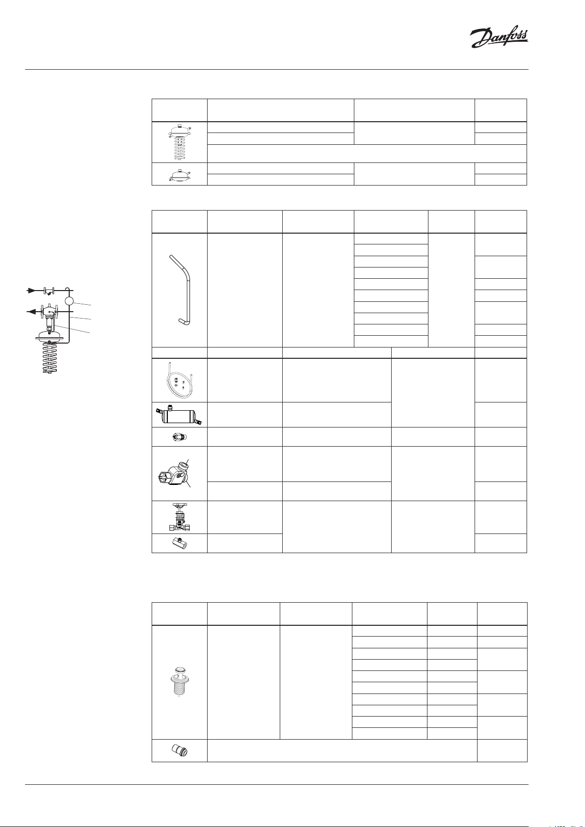
Accessories
Picture Type designation For controller
Impulse tubes
(Stainless steel)
Picture Type designation Description Ordering number Code No.
Impulse tube set AF
Seal pot V1
Compression fitting
port B
Combination piece KF3
3)
port A
Combination piece KF2
1)
2)
AFPB
– 1× Copper tube
Ø10 × 1 × 150 0 mm
– 1 × compression fitting for imp.
tube connection to pipe (G 1/)
– 2 × socket
Capacit y 1 liter; with compression
fittings for imp. tube Ø10
For impulse tube Ø10 connections
to controller
For combination with pressure
actuators. Electrical actuator
connected on side (port B)
only for ON/OFF function
For combination with thermostat side connection to port B
DN
(mm)
15
20
25
32
40 003G1359
50 00 3G1360
65
80
100 00 3G1363
125 0 03G136 4
G 11//2× G 11/
PN Code No.
16, 25, 40
–
G 1/ 003G1468
00 3G1017
003 G1026
00 3G1355
00 3G1357
00 3G1361
003G1391
003G1392
00 3G1441
00 3G1440
Shut off valve
Throttle valve 065B2909
1)
Seal pot has to b e used on impulse tubes alwa ys when Tmax ≥ 150 °C
2)
Consist of a nipple , compression ring and nut
3)
Port A - for conn ection of any type of ac tuator
For impulse tube Ø10 –
00 3G1401
Service kits
Picture Type designation For valve
Valve insert VFQ 2
Stuffing cone (with EPDM O -rings) 003G1464
DN
(mm)
15 4.0 065B2796
20 6.3 065B2797
25 8
32 16
40 20
50 32
65 50
80 80
100 125
125 160
k
VS
(m3/h)
Code No.
065B2798
065B2799
065B2800
065B2801
2 | VD.AC.B7.02 © Danfoss | 2018.10
Page 3
Data sheet Differential pressure controller with flow limitation AFPB(-F) / VFQ 2(1) (PN 16, 25, 40)
2
Technical data
Valve
Nominal diameter DN 15 20 25 32 40 50 65 80 100 125
kVS value
Range
of max.
flow
setting
pSPp
0.2 0 .1
1)
0.5 0.3
1.0 0.5
SISTEM
0.1/0.2/0.5 from
p
0.1
0.2
0.5
b
Cavitation factor z 0.6 0.6 0.6 0. 55 0.55 0.5 0.5 0.45 0.4 0.35
Leakage acc. to
standard IEC 534 (% of kVS)
Nominal pressure PN 16, 25, 40
Min. differential pressure
Max. differential pressure
PN 25, 40 20
Media Circulation water/glycolic water up to 30 %
Media pH Min. 7, max. 10
Media temperature
VFQ 21 2 … 150
Connections Flange
Materials
Valve body
Valve seat Stainless steel, mat. No. 1.4021
Valve cone Stainless steel, mat. No. 1.4404
Sealing
Pressure relieve system Bellows (Stainless steel, mat. No. 1.4571)
1)
Max. flow rate depends o n the differential pressur e over the system (dp System). System is part of the a pplication where dif ferential
pressure is controll ed by AFPB(-F) and for this part the re sistance is well known/defined .
Flow rates in table are sp recified for 3 diffe rent situations.
pSP = p
∆pSP -diff erential pressure set point
∆p
SYSTEM
∆pb -diff erential pressure over flow re strictor
2)
Depends o n the flow rate and valve kVS ; For Q
3)
at temperature s above 150 °C only with sea l pots (see Accessories)
+ p
System
b
-system dife rential pressure
m3/h
4.0 6.3 8.0 16 20 32 50 80 125 160
0.05 0.15 0.25 0.4 0.6 0.9 2 3.5 6.5 11
to 1.4 2.1 2.5 5 6.5 10 16 25 40 50
m3/h
to 2 3 4 7 11 16 28 40 63 80
to 3 4.5 6 10 16 24 40 58 90 12 0
VFQ 2 ≤ 0.03
VFQ 21 ≤ 0.01
2)
3)
PN 16 16
VFQ 2
bar
°C
see remark
2 … 150/2 … 200
PN 16 Grey cast iron EN-GJL-250 (GG-25)
PN 25 Ductile iron EN-GJS-400(GGG- 40.3)
PN 40 Cast steel GP240 GH (GS-C 25)
VFQ 2 Metal
VFQ 21 EPDM
= Q
–> p
set
max
≥ 0.5 bar; For Q
min
< Q
–>
set
max
Q
p
min
p
b
k
VS
15
Actuator
Typ e AFPB AFPB-F
Actuator size cm
Max. operational pressure PN 25
Diff. pressure setting ranges and spring
colours
Materials
Actuator housing Steel, mat. No.1.0338, zinc plated
Control diaphragm EPDM (Rolling; fibre enforced)
bar
2
250
0.1-0.7 0.15-1.5 0.2 0.5
yellow red fixed setting
VD.AC.B7.02 | 3© Danfoss | 2018.10
Page 4
Data sheet Differential pressure controller with flow limitation AFPB(-F) / VFQ 2(1) (PN 16, 25, 40)
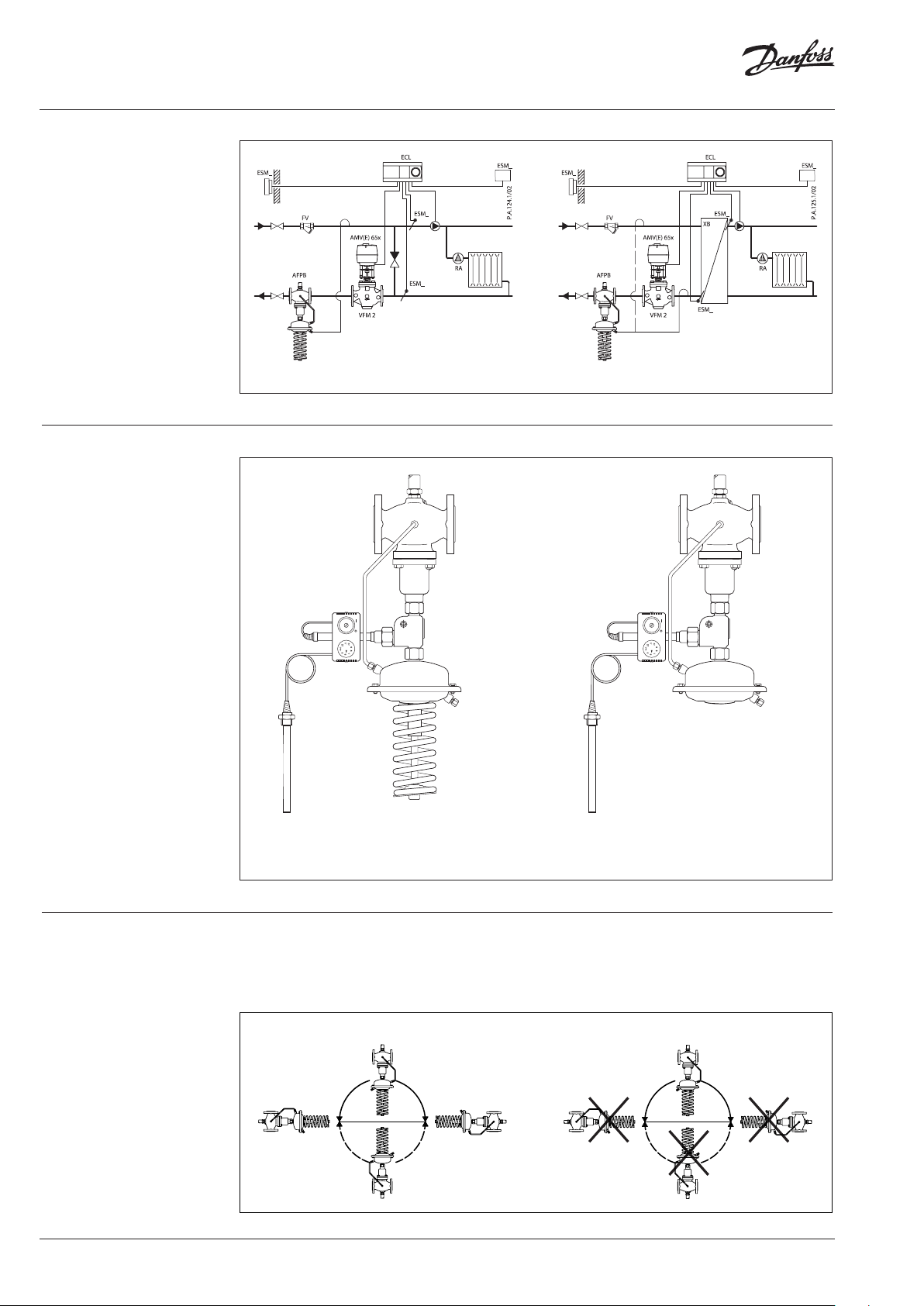
Application principles
AFPB controller must be installed in
the return pipe only.
Direct-connected heating system Indirectly connected heating system
Combinations
Example:
Differential pressure and
temperature controller with f low
limitation; return mounting; DN
15; kVS 4.0; PN 16; metallic sealing;
setting range 0.1-0.7 bar; t
°C; flange;
max
150
– 1× VFQ 2 DN 15 valve
Code no: 065B2654
– 1× AFPB actuator
Code no: 00 3G1017
– 2× Impulse tube set AF
Code no: 003G1391
– 1× AFT06 thermostat
Code no: 065-4390
– 1× Combination piece KF2
Code no: 003G14 40
Products will be delievered
separatelly.
Note:
For AFT 06 thermostat data see
relevant data sheet
AFT 06/KF2/AFPB/VFQ 2
– Differential pressure and temperature controller with
flow limitation, adjustable setting.
Installation positions DN 15-80 T
The controllers can be installed in any position.
DN 15-80 T
≤ 120 °C
max
≤ 120 °C
max
AFT 06/KF2/AFPB-F/VFQ 2
– Differential pressure and temperature controller with
flow limitation, fixed setting.
DN 15-80 T
The controllers can be installed in horizontal
> 120 °C; DN 100-125
max
pipes only, with a pressure actuator oriented
downwards.
DN 15-80 T
> 120 °C; DN 100-125
max
4 | VD.AC.B7.02 © Danfoss | 2018.10
Page 5

Data sheet Differential pressure controller with flow limitation AFPB(-F) / VFQ 2(1) (PN 16, 25, 40)
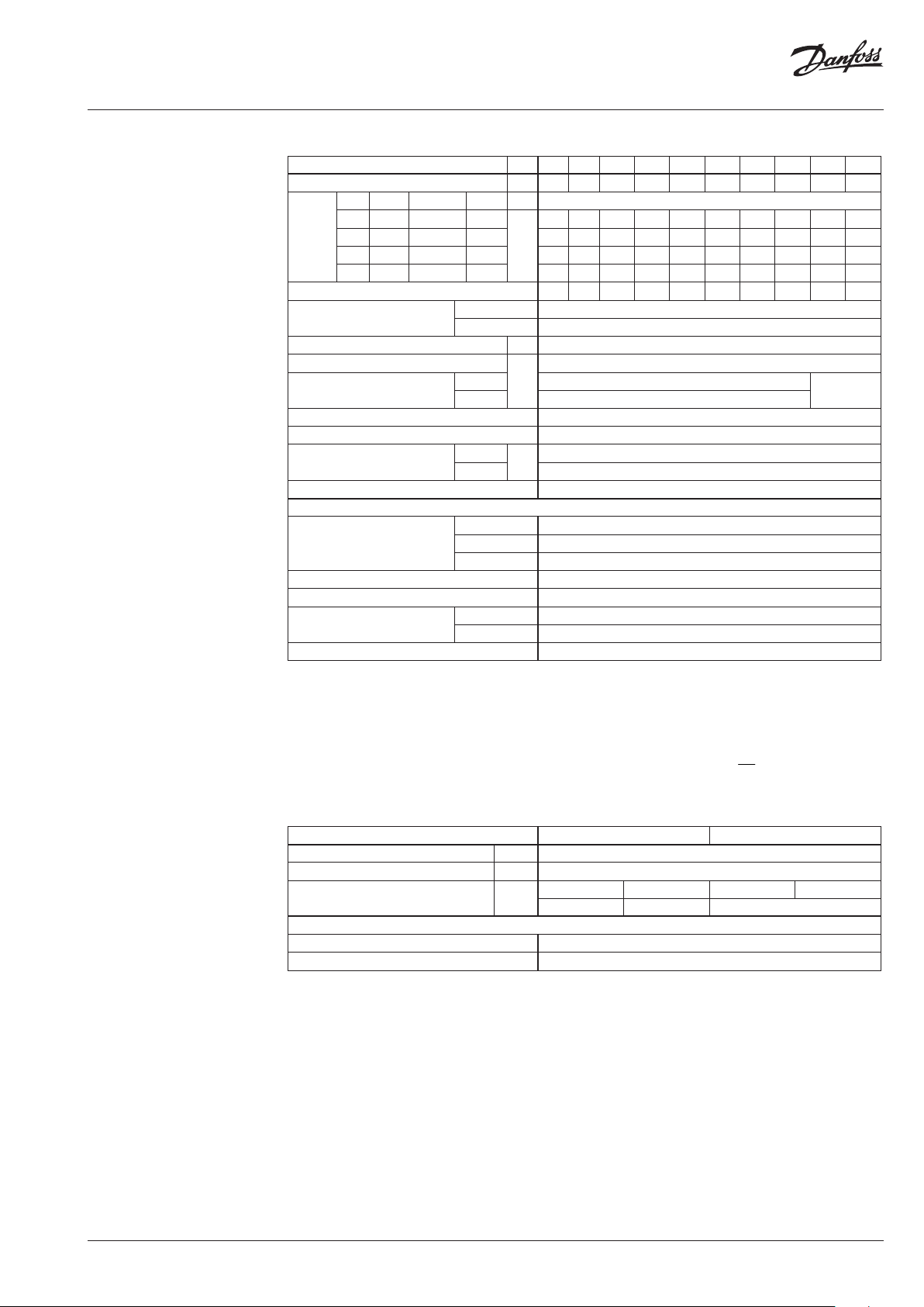
Pressure temperature
diagram
Working area is below P-T line
and it ends at Tmax for each
valve
Maximum allowed operating pressure as a function of media temperature (according to EN 1092-2)
PN 16
EN - GJL- 250
(GG -25)
PN 25
EN-GJS- 400
(GGG-40.3)
Maximum allowed operating pressure as a function of media temperature (according to EN 1092-2)
PN 40
EN-GP-240-GH
(GS- C 25)
Maximum allowed operating pressure as a function of media temperature (according to EN 1092-1)
VD.AC.B7.02 | 5© Danfoss | 2018.10
Page 6

Data sheet Differential pressure controller with flow limitation AFPB(-F) / VFQ 2(1) (PN 16, 25, 40)
Sizing
– Directly connected heating
system
Example 1
Motorised control valve (MCV) for mixing circuit
in direct-connected heating system requires
differential pressure of 0.3 bar (30 kPa) and flow
less than 1800 l/h.
Given data:
Q
= 1.8 m3/h (1800 l/h)
max
p
= 0.7 bar (70 kPa)
min
1)
p
= 0.1 bar (10 kPa)
circuit
p
= 0.3 bar (30 kPa) selected
MCV
2)
p
= 0.1 bar (10 kPa) assumption
b
Remark:
1)
∆p
corresponds to the r equired pump pressure in t he heating
circuit
circuit and is not to b e considered when sizing the AFPB .
2)
pb is differe ntial pressure over flow restri ctor.
The differential pressure set value is:
p
p
= pb + p
set value
= 0.4 bar (40 kPa)
set value
= 0.1 + 0.3
MCV
The total pressure loss across the controller is:
p
= p
AFPB
p
= 0.4 bar (40 kPa)
AFPB
min
− p
= 0.7 − 0.3
MCV
Possible pipe pressure losses in tubes, shut-off
fittings, heatmeters, etc. are not included.
kv value is calculated according to formula:
Q
k
v
max
pp
bAFPB
8.1
1.04.0
kv = 3.3 m3/h
Solution:
The example selects AFPB/VFQ 2 DN 15; kVS value
4.0; with differential pressure setting range
0.1-0.7 bar; flow setting range 0.05-1.4 m3/h.
If other differential pressure is assumed than pb
= 0.1 bar, in order to maintain the kVS value, the
flow has to be adjusted using the flow restrictor
screw. The new set value (Q-setting) of the
assumed differential pressure
(p
= 0.2 bar) is calculated according to
b NEW
formula:
p
b
Q
setting
p
Q
max
NEW b
∆p
Q
max
min
AFPB
∆p
b
∆p
AFPB
∆p
MCV
∆p
circuit
6 | VD.AC.B7.02 © Danfoss | 2018.10
Page 7

Data sheet Differential pressure controller with flow limitation AFPB(-F) / VFQ 2(1) (PN 16, 25, 40)
bAFPB
Sizing (continuous)
– Indirectly connected heating
system
Example 2
Motorised control valve (MCV) for indirectly
connected heating system requires differential
pressure of 0.3 (30 kPa) bar and flow less than
130 0 l/ h.
Given data:
Q
= 1.3 m3/h (1300 l/h)
max
p
= 1.0 bar (100 kPa)
min
p
p
p
Remark:
1)
pb is differe ntial pressure over flow restri ctor
= 0.05 bar (5 kPa)
exchanger
= 0.3 bar (30 kPa) selected
MCV
1)
= 0.2 bar (20 kPa) assumption
b
The differential pressure set value is:
p
p
p
= pb + p
set value
= 0.2 + 0.05 + 0.3
set value
= 0.55 bar (55 kPa)
set value
exchanger
+ p
MCV
The total pressure loss across the controller is:
p
= p
AFPB
p
= 1.0 − 0.05 − 0.3
AFPB
p
= 0.65 bar (65 kPa)
AFPB
min
− p
exchanger
− p
MCV
Possible pipe pressure losses in tubes, shut-off
fittings, heatmeters, etc. are not included.
kv value is calculated according to formula:
Q
k
v
max
pp
3.1
2.065.0
kv = 1.9 m3/h
Solution:
The example selects AFPB/VFQ 2 DN 15; kVS value
4.0; with differential pressure setting range
0.1-0.7 bar; flow setting range 0.05-2.0 m3/h.
If other differential pressure is assumed than pb
= 0.2 bar, in order to maintain the kVS value, the
flow has to be adjusted using the flow restrictor
screw. The new set value (Q-setting) of the
assumed differential pressure
(p
= 0.1 bar) is calculated according to
b NEW
formula:
p
b
Q
setting
p
Q
max
NEW b
∆p
Q
max
min
AFPB
∆p
b
∆p
AFPB
∆p
MCV
∆p
exchanger
VD.AC.B7.02 | 7© Danfoss | 2018.10
Page 8
Data sheet Differential pressure controller with flow limitation AFPB(-F) / VFQ 2(1) (PN 16, 25, 40)
17
15
16
19
18
10
11
18
20
9
2
13
17
15
16
19
18
10
11
18
20
12
9
2
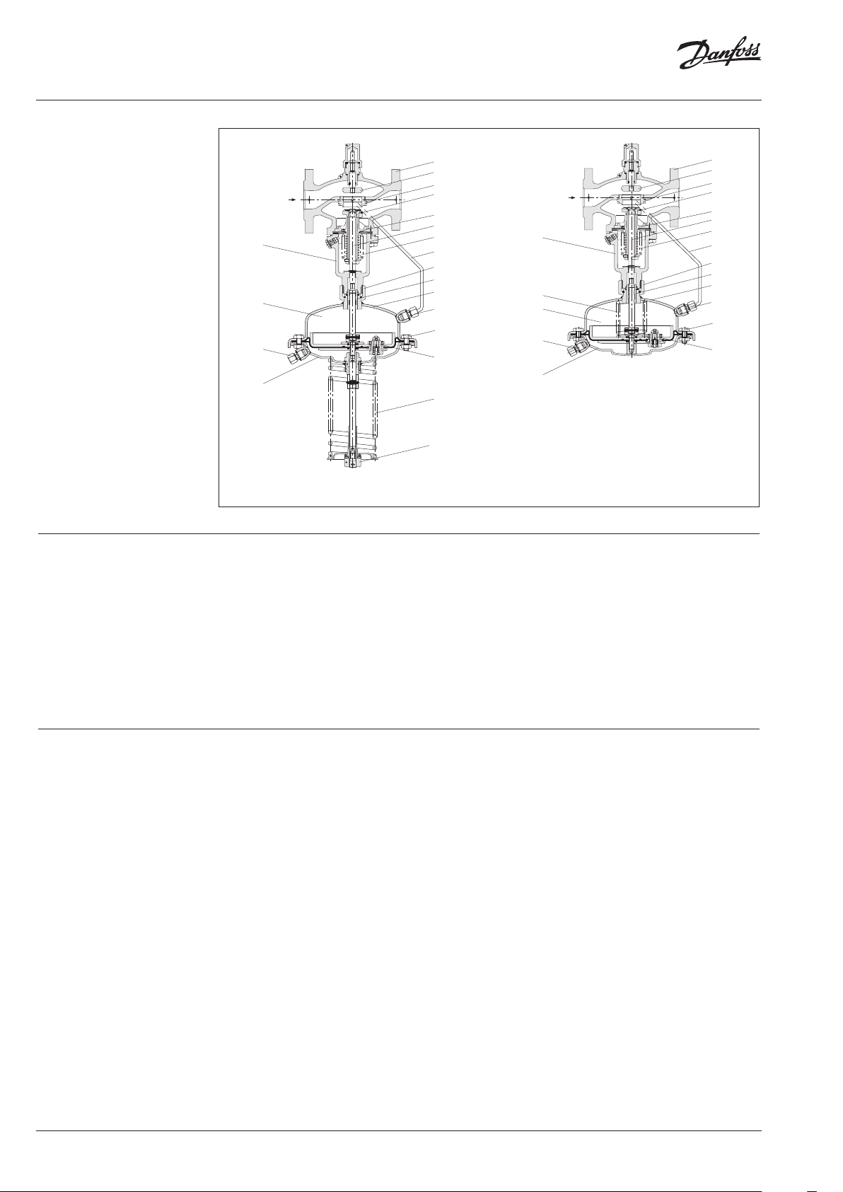
Design
1. Valve body
2. Cover
3. Adjustable flow restrictor
4. Valve seat
5. Valve insert
6. Pressure relieved valve cone
7. Valve stem
8. Bellows for pressure relief of
valve cone
9. Actuator
10. Control diaphragm for
differential pressure and flow
control
11. Excess pressure safey valve
12. Built in spring for differential
pressure and flow control
13. Setting spring for diff.
pressure control
14. Adjuster for diff. pressure
setting, prepared for sealing
15. Stuffing cone
16. Union nut
17. Impulse tube
18. Compression fitting for
impulse tube
19. Upper casing of diaphragm
20. Lower casing of diaphragm
AFPB/VFQ 2 DN 15 – 125
1
3
4
6
5
7
8
AFPB-F/VFQ 2 DN 15 – 125
14
1
3
4
6
5
7
8
Function
Pressure changes from flow and return pipes are
being transferred through the impulse tubes
to the actuator chambers and act on control
diaphragm for diff. pressure and flow control.
Controller is equipped with excess pressure
safety valve, which protects control diaphragm
for diff. pressure and flow control from too high
differential pressure.
The diff. pressure is controlled by means of
setting spring for diff. pressure control. Control
valve closes on rising differential pressure and
opens on falling differential pressure to maintain
constant differential pressure. Flow volume is
limited by means of the flow restrictor.
Settings Differential pressure setting
8 | VD.AC.B7.02 © Danfoss | 2018.10
Flow setting
Flow setting is being done by the adjustment of
the flow restrictor position. The adjustment can
be performed on the basis of flow adjustment
diagram (see relevant instructions) and/or by the
means of heat meter.
Differential pressure setting is being done by the
adjustment of the setting spring for diff. pressure
control. The adjustment can be done by means
of adjuster for diff. pressure setting and pressure
indicators.
Page 9

Data sheet Differential pressure controller with flow limitation AFPB(-F) / VFQ 2(1) (PN 16, 25, 40)
A
ø89
Dimensions
L
2
B
H
B
VFQ DN 15-125
VFQ 2, VFQ 21 Valves
DN 15 20 25 32 40 50 65 80 100 12 5
L
B 213 213 239 239 241 241 276 276 381 381
B
2
H 337 337 3 74 374 393 393 440 440 575 575
PN 16/25
Weight
PN 40 31 34 63 72
130 150 16 0 180 200 230 290 310 350 400
mm
124 124 135 13 5 152 152 16 4 164 194 194
kg 8 9 10 .5 12 .5 15.5 18 .5
28.5 31 61 71
ø60
AFPB Actuator
110
78
Ø10
mm
2
250
263
SW 22
H
Actuator size cm
Ø A
H 457
Weight kg 9
Shut off valve
AFPB-F Actuator
H
A
Actuator size cm
Ø A
H 160
Weight kg 9
240
Seal pot V1
2
250
mm
263
Comb. piece KF2, KF3
40
G⁄
SW19
Compression fitting
VD.AC.B7.02 | 9© Danfoss | 2018.10
Page 10

Data sheet Differential pressure controller with flow limitation AFPB(-F) / VFQ 2(1) (PN 16, 25, 40)
10 | VD.AC.B7.02 © Danfoss | 2018.10
Page 11

Data sheet Differential pressure controller with flow limitation AFPB(-F) / VFQ 2(1) (PN 16, 25, 40)
VD.AC.B7.02 | 11© Danfoss | 2018.10
Page 12
Data sheet Differential pressure controller with flow limitation AFPB(-F) / VFQ 2(1) (PN 16, 25, 40)
© Danfoss | DHS-SRMT/SI | 2018.1012 | VD.AC.B7.02
 Loading...