

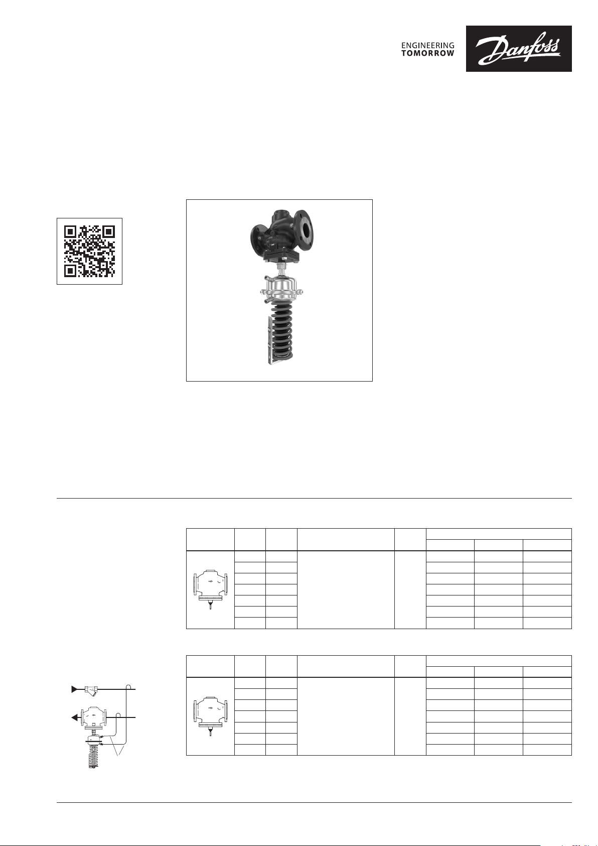
Data sheet
Differential pressure controller (PN 16, 25, 40)
AFP 2 / VFG 22(1) – return and flow mounting, adjustable setting
Description
virtus.danfoss.com
The controller is a self-acting differential pressure
controller primarily for use in district heating
systems. Direct operated, reliable and high
precise controller closes on rising differential
pressure.
The controller has a control valve, an actuator
with one control diaphragm and spring for
differential pressure setting.
Further on two valve versions are available:
∙ VFG 22 with metallic sealing cone
∙ VFG 221 with soft sealing cone
Together with Danfoss intelligent electrical
actuator AMEi 6 intelligent optimization
functions are available:
∙ iSET-intelligent substation efficiency
optimization
∙ iNET-intelligent network balancing
Main data:
∙ DN 65-250
∙ kVS 60-800 m3/h
∙ PN 16, 25, 40
∙ Setting range:
0.1-0.35 bar / 0.1-1 bar / 0.5-1.5 bar /
/ 1-2.5 bar / 1.5-4 bar / 1-3 bar / 1.5-5 bar
∙ Temperature:
– Circulation water / glycolic water up to 30%:
2 … 150°C
∙ Connections:
– Flange
Ordering
Example 1:
Differential pressure controller,
return mounting, DN 65, kVS 60,
PN 16, metallic sealing, setting
range 1.5-4 bar, T
– 1× VFG 22 DN 65 valve
Code no: 065B5500
– 1× AFP 2 actuator
Code no: 003G5606
– 2× Impulse tube set AF
Code no: 00 3G1391
Products will be delivered
separately.
150 °C, flange
max
Impulse tube set AF
VFG 22 Valve (metallic sealing cone)
Picture
DN
(mm)
65 60
80 80 065B5501 065B5508 065B5515
100 160 065B5502 065B5509 065 B5516
125 250 065B5503 065B5510 06 5B5517
150 380 065B5504 0 65B5 511 06 5B5518
200 650 065B5505 065 B5512 06 5B5519
250 800 065B5506 06 5B5513 065B5520
k
VS
(m3/h)
Flanges acc. to EN 1092-1 150
VFG 221 Valve (soft sealing cone)
Picture
DN
(mm)
65 60
80 80 065B5522 065B5529 065 B5536
100 16 0 065 B5523 065B5530 065B5537
125 250 065B5524 065B5531 065B5538
150 380 065B5525 065B5532 065B5539
200 650 0 65B5526 065B5533 065B5540
250 800 065B5527 065B5534 065B5541
k
VS
(m3/h)
Flanges acc. to EN 1092-1 150
Connections
Connections
T
(°C)
T
(°C)
max.
max.
PN 16 PN 25 PN 40
065B5500 065B5507 06 5B5514
PN 16 PN 25 PN 40
065 B5521 065B5528 065B5535
Code No.
Code No.
© Danfoss | 2022.01 AI268355020467en-010304 | 1
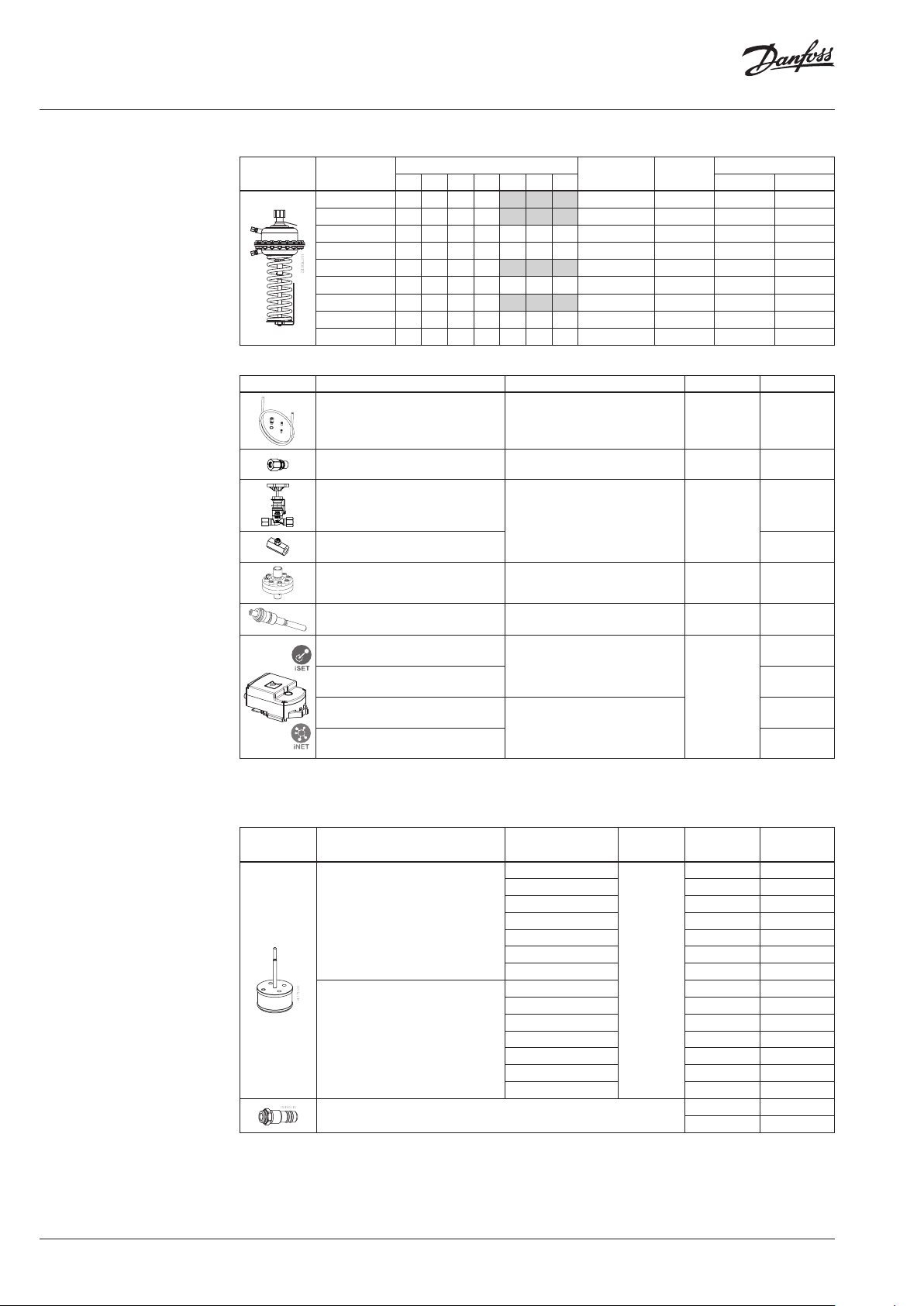
Data sheet Differential pressure controller AFP 2 / VFG 22(1) (PN 16, 25, 40)
Ordering (continuous)
AFP 2 Actuator
Picture
Setting range
(bar)
1.5 -5
1-3
1.5 -4
1-2. 5
0.5-1.5
0.4-1.5
0.1-1
0.1-1
0.1-0.35
Possible combinations with DN
65 80 10 0 125 150 200 250
- - - 80 red 003G5604 003G5614
- - - 80 yellow 003G5605 003G5615
- - - 160 yellow 003G5608 003G5618
- - - 160 blue 003G5612 003G5622
Actuator size
(cm)
Spring
colour
160 black 1) 003G5606 003G5616
160 red 003G5607 003G5617
320 red 003G5609 003G5619
320 orange 003G5610 003G5620
640 yellow 003G5611 003G5621
Code No.
PN 16 PN 40
Accessories
Picture Type designation Description Connections Code No.
– 1× Copper tube Ø10 × 1 × 1500 mm
Impulse tube set AF
Compression fitting
2)
Shut off valve
Static throt tle valve 065B2909
Dynamic throttle valve
3)
– 1× compression fitting for imp.
tube connection to pipe (G ⁄)
– 2× socket
For impulse tube Ø10 connections
to controller
For impulse tube Ø10 –
For impulse tube Ø10 /
connection to pressure actuator
– 003G1391
G⁄ 00 3G1468
G⁄ 003G177 1
00 3G1401
Adapter new AFP 2old VFG DN 15 -250 0 03G17 80
AMEi 6 iSET
el actuator 230 V
AMEi 6
iSET
el actuator 24 V
AMEi 6 iNET
el actuator 230 V
AMEi 6 iNET
el actuator 24 V
1)
Combination w ith AMEi 6 not possible
2)
Consist of a nippl e, compression ring and nut
3)
Available in 2022
Service kits
Picture Typ e
Pressure control
inser t VFG/Q/22
Pressure control
ins ert V FG/Q/ 221
Pressure stuffing box VFG/Q /221
Intelligent p actuator with iSET
function
Intelligent p actuator with iNET
function
k
VS
(m3/h)
60
PN DN Code No.
65 003G1800
80 80 0 03G1801
160 100 003G18 02
250 125 003G1803
380 150 0 03G180 4
650 200 0 03G1805
800 250 003 G1806
60 65 0 03G1807
16/2 5/40
80 80 00 3G1808
160 100 003G18 09
250 125 00 3G1810
380 150 0 03G1 811
650 200 00 3G1812
800 250 0 03G1813
65 -125 003G1730
150-250 003G1731
082G4300
082G4301
082G4302
082G4303
2 | AI268355020467en-010304 © Danfoss | 2022.01
Data sheet Differential pressure controller AFP 2 / VFG 22(1) (PN 16, 25, 40)
Technical data
Valve
Nominal diameter DN 65 80 100 125 150 200 250
kVS value
Leakage acc. to standard
IEC 534 (% of kVS)
Nominal pressure PN 16, 25, 40
Max. differential
pressure
Pressure relieve system Chamber relieved
Media Circulation water / glycolic water up to 30%
Media pH Min. 7, max. 10
Media temperature VF G 22(1) °C 2 … 150
Connections Flange
Materials
Valve body
Valve seat Stainless steel, mat. No. 1.4021
Valve cone Stainless steel, mat. No. 1.4021
Sealing
VFG 22 ≤ 0.03 ≤ 0.05
VFG 221 ≤ 0.01
PN 16
PN 25, 40 20
PN 16 Grey cast iron EN-GJL-250 (GG-25)
PN 25 Ductile iron EN-GJS-400(GGG-40.3)
PN 40 Cast steel GP240GH (GS-C 25)
VFG 22 Metal
VFG 221 EPDM
m3/h
bar
60 80 160 250 380 650 800
16
15 12 10
AFP 2 Actuator
Actuator size cm
Max. operating pressure bar 16, 4 0
Diff. pressure setting ranges and
spring colours
For valve DN 6 5-125 65-2 50 65-125 65 -125 65-250 65-2 50
Materials
Actuator housing Steel, mat. No. 1.0345, zinc plated
Control diaphragm EPDM
1)
Combination w ith AMEi 6 not possible
2
80 160 320 640
red yellow black 1)red yellow blue red orange yellow
bar
1.5 -5 1-3 1.5-4 1-2.5 0.5-1.5 0.1-1 0 .4-1. 5 0.1-1 0.1-0.35
DN 65
DN 80
cavitation factor z
DN 100
flow (m3/h)
DN 12 5
DN 150
DN 200
DN 250
cavitation factor z
flow (m3/h)
AI268355020467en-010304 | 3© Danfoss | 2022.01

Data sheet Differential pressure controller AFP 2 / VFG 22(1) (PN 16, 25, 40)
p
at z = 0,2 ... 0,6 [bar]
Inlet pressure bar p [bar]
z =
Example :
Operating area
Maximum allowed differential pressure over the controller (p
max
T = 90°C
T = 100°C
T = 110°C
[bar]
max
p
) at different cavitation factors (z)
max
p = 6 bar
T = 140°C
z = 0,4
= 1,35 bar
p
max
T = 80°C
T = 130°C
T = 140°C
T = 150°C
Application principles
– Return mounting
– Flow mounting
Direct-connected heating system Indirectly connected heating system
Direct-connected heating system
Indirectly connected heating system
4 | AI268355020467en-010304 © Danfoss | 2022.01

Data sheet Differential pressure controller AFP 2 / VFG 22(1) (PN 16, 25, 40)
Installation position
The controllers can be installed in any position.
Pressure temperature
diagram
Working area is below P-T line and it
ends at T
for each valve
max
PN 25
PN 16
EN - GJL- 250
(GG -25)
150
150
Maximum allowed operating pressure as a function of media temperature (according to EN 1092-2)
PN 40
EN-GP-240-GH
(GS- C 25)
150
Maximum allowed operating pressure as a function of media temperature (according to EN 1092-1)
EN-GJS-400
(GGG-40.3)
AI268355020467en-010304 | 5© Danfoss | 2022.01

Data sheet Differential pressure controller AFP 2 / VFG 22(1) (PN 16, 25, 40)
( )
=−=−=
Sizing Example:
The application demands a maximal flow of
25m3/h and has a motorized control valve (MCV)
that needs a control of a pressure drop 0.4 bar.
The minimal differential pressure available over
MCV and AFP is 0.7 bar.
Given D ata:
Q
= 25 m3/h
max
p
= 0.7 bar
min
p
= 0.4 bar
MCV
The total pressure across the controller is:
MCVminAFP
kPa 30bar 0.30.40.7ΔpΔpΔp
Calculate the kv value:
AFP
25
0.3
Q
max
k
v
p
The first bigger kVS to 45.6 m3/h is 60 m3/h and
gives VFG DN 65.
The available setting range to control 0.4 bar is
0.1-0.7 bar and is available for DN 65.
Solution:
AFP 2 0.1-0.7
VFG 22 (221) DN 65 kVS 60
3
hm 45.6
∆p
∆p
AFP
∆p
MCV
min
6 | AI268355020467en-010304 © Danfoss | 2022.01

Data sheet Differential pressure controller AFP 2 / VFG 22(1) (PN 16, 25, 40)
Design
1. Valve body
2. Valve seat
3. Pressure control insert
4. Pressure actuator
5. Pressure control cone
6. Pressure stuffing box
7. Cover
8. Impulse tube connection
9. Diaphragm
10. Diaphragm excess pressure
safety valve
11. Differential pressure setting
spring
12 . Differential pressure setting
nut
13. Setting scale
14 . Setting indicator
15. Union nut
16. Impulse tube
Function
The differential pressure control is achieved by
maintaining a constant differential pressure over
the control valve/application.
The differential pressure over the control valve is
lead to the pressure actuator diaphragm through
the impulse tubes.
The opening/closing of the pressure control cone
is performed by changing differential pressure
over the diaphragm.
Settings Differential pressure setting
Differential pressure setting is being done by the
adjustment of the setting spring for diff. pressure
control. This is done by rotating the differential
pressure setting nut. Set differential pressure
should be checked by observing the pressure
indicators.
When differential pressure over the control valve:
a) rises, the pressure control cone takes over
the exceeded differential pressure by closing,
until set differential pressure over the control
valve/application is reached.
b) drops, the pressure control cone compensates
the missing differential pressure by opening,
until set differential pressure over the control
valve/application is reached.
The pressure actuator diaphragm is equipped
with excess pressure safety valve to protect
diaphragm from the damages caused by too
high differential pressure.
AI268355020467en-010304 | 7© Danfoss | 2022.01
Data sheet Differential pressure controller AFP 2 / VFG 22(1) (PN 16, 25, 40)
Dimensions
L
V
H
B
H
VFG 22(1) DN 65-250
VFG 22, VFG 221 Valves
Weight
PN 16 PN 25 PN 40
DN
L B H H
V
mm kg
65 290 245 370 285 24 24 27
80 310 24 0 365 290 29 29 32
100 350 275 42 5 350 47 48 53
125 400 270 435 370 60 60 68
150 480 330 520 460 105 106 121
200 600 365 610 550 204 206 235
250 730 420 680 620 343 350 404
A
H
ØA
Ø60
SW 22
78
Shut off valve
AFP 2 Actuator
Size ØA HAH
(cm2)
mm
AI
AFP 2 PN 16
80 17 5 490 590 9 11 .5 16 18. 5
160 230 510 610 11 .5 14 23.5 26
320 300 510 610 15 17. 5 35.5 38
640 300 630 730 38 40.5 58 60.5
Total installation heig ht of the controller (VFG 22(1) valve + AFP 2 pressure
actuator) is sum of HV and HA (H
)
AI
Ø10
110
40
G⁄
SW19
Compression fitting
Weight [kg]
AFP 2 PN 16
+ AMEi 6
AFP 2 PN 40
AFP 2 PN 40
+ AMEi 6
ØA
AI
H
AMEi 6 intellig ent
actuator wit h iSET/ iNET
functionality should be
ordered sep arately
min. 250
© Danfoss | DCS-SGDPT/SI | 2022.018 | AI268355020467en-010304
 Loading...