

Page 1
MAKING MODERN LIVING POSSIBLE
Operating Instructions
VLT® Active Front End AFE 302
www.danfoss.com/drives
Page 2

Page 3

Contents Operating Instructions
Contents
1 Introduction
1.1 Purpose of the Manual
1.2 Safety Symbols
1.3 Software Version
1.4 Approvals
1.5 Abbreviations
2 Safety Instructions and General Warning
2.1 Safety Regulations AFE 302
2.1.1 Disposal Instruction 6
2.1.2 High Voltage Warning 6
2.1.3 Safety Instructions 6
2.1.4 General Warnings 6
2.1.5 Before Commencing Repair Work 6
2.1.6 System Description 6
3 Crane System Design
3.1 Selection of Motor Voltage
4
4
4
4
4
5
6
6
8
8
3.1.1 Selection of AFE & LCL Filter 8
3.1.2 Selection of AFE for Different Applications 8
3.1.3 Selection of Output Filter (LC Filter) 8
3.1.4 Selection of Switching Frequency 8
3.1.5 Selection of LCL Filter 8
3.1.6 Crane Cable Concept 8
3.1.7 Grounding Concept 9
3.1.8 Cooling and Airflow 9
3.1.9 Selection of Transformer 10
3.2 Assembling the Frequency Converter System
3.2.1 Tools Required 11
3.2.2 General Tightening Torque Values 11
3.2.3 Exploded Views 11
3.2.4 MDCIC Connector Configuration 17
3.3 First Power Up/Commissioning Check List
3.4 E-House Design
3.4.1 Cables between AFE and LCL Filters 18
11
17
18
3.4.2 Cables to the Damping Resistors 18
3.5 Test with the Real System Transformer and Motors
3.5.1 Re-program the Frequency Converter Parameters 18
3.6 On-site Final Test
3.6.1 Change Parameters to Actual 18
MG33X402 Danfoss A/S © Rev. 05/2014 All rights reserved. 1
18
18
Page 4

Contents Operating Instructions
3.6.2 Run with Full Load 18
3.7 AFE Emergency and Restore Procedures
3.7.1 Emergency Run when One Slave Unit is Damaged 18
3.7.2 Restoration after Slave Unit is Repaired 19
3.7.3 Emergency Run when Master Unit is Damaged 19
3.7.4 Restoration after Master Unit is Repaired 20
3.7.5 Emergency Run When More Than One Unit is Damaged 20
3.8 Manual Shut Down Sequence
3.9 Start-up Sequence
3.10 Shut-down Sequence
4 How to Install
4.1 Overall Typical Frequency Converter Configuration
4.2 Pre-installation
4.2.1 Planning the Installation Site 24
4.2.2 Receiving the Frequency Converter 24
4.2.3 Transportation and Unpacking 24
4.2.4 Lifting 26
4.2.5 Mechanical Dimensions 27
18
20
21
22
23
23
24
4.2.6 Weight Information 31
4.3 Mechanical Installation
4.3.1 Tools Needed 32
4.3.2 General Considerations 32
4.3.3 Terminal Locations 32
4.3.4 Mains Torque 33
4.3.5 Mains Connection 33
4.3.6 Screened Cables 33
4.4 Electrical Installation
4.4.1 Control Wires 36
4.4.2 Power Connections 36
4.4.3 Grounding 36
4.4.4 Electrical Installation, Control Terminals 37
5 Specifications
5.1 General Specifications
5.2 Mains Supply
32
35
38
38
42
6 How to Programme
6.1 Parameter Selection
6.2 Parameters: 0-** Operation and Display
6.3 Parameters: 4-** Limits/Warnings
2 Danfoss A/S © Rev. 05/2014 All rights reserved. MG33X402
43
43
44
48
Page 5

Contents Operating Instructions
6.4 Parameters: 5-** Digital In/Out
6.5 Parameters: 6-** Analog In/Out
6.6 Parameters: 7-** Controllers
6.7 Parameters: 8-** Communications and Options
6.8 Parameters: 14-** Special Functions
6.9 Parameters: 15-** AFE Information
6.10 Parameters: 16-** Data Read-outs
6.11 Parameters: 40-** Mains / Filter
6.12 Warnings/Alarm Messages
Index
49
52
53
54
57
59
62
64
65
71
MG33X402 Danfoss A/S © Rev. 05/2014 All rights reserved. 3
Page 6
Introduction Operating Instructions
1
1 Introduction
1.1 Purpose of the Manual
1.1.1 How to Read these Operating
Instructions
Please read this manual carefully for proper use. Incorrect
handling of the frequency converter may cause improper
operation of the frequency converter or related equipment,
shorten lifetime or cause other troubles.
These Operating Instructions will help getting started,
installing, programming, and troubleshooting the AFE 302.
Chapter 1 Introduction, introduces the manual and informs
about the approvals, symbols, and abbreviations used in
this literature.
Chapter 2 Safety Instructions and General Warning, entails
instructions on how to handle the AFE 302 correctly.
1.3 Software Version
VLT® Active Front End AFE 302
Operating Instructions
Software version: 1.15
1.4 Approvals
Table 1.1 Compliance Marks: CE and C-Tick
Chapter 3 Crane System Design, describes the crane system
design associated with the frequency converters.
Chapter 4 How to Install, guides through the mechanical
and technical installation.
Chapter 6 How to Programme, describes how to operate
and programme the AFE 302 via the Local Control Panel
(LCP).
1.2
Safety Symbols
The following symbols are used in this document:
WARNING
Indicates a potentially hazardous situation which could
result in death or serious injury.
CAUTION
Indicates a potentially hazardous situation which could
result in minor or moderate injury. It can also be used to
alert against unsafe practices.
NOTICE
Indicates important information, including situations that
can result in damage to equipment or property.
4 Danfoss A/S © Rev. 05/2014 All rights reserved. MG33X402
Page 7
Introduction Operating Instructions
1.5 Abbreviations
1
1
AFE Active Front End
AC Alternating current
AWG American Wire Gage
A Ampere/AMP
AMA Automatic Motor Adaptation
I
LIM
°C
DC Direct current
EMC Electro Magnetic Compatibility
ETR Electronic Thermal Relay
FC Frequency Converter
g Gram
Hz Hertz
HF High Frequency
ID Identification
IGBT Insulated Gate Biopolar Transistor
IP International Protection
IT Isolation Terra
kHz Kilohertz
kW Kilowatt
kWh Kilowatt-hour
LCP Local Control Panel
MW Megawatt
m Meter
uF Microfarad
mH Millihenry Inductance
mA Milliampere
MCM Thousand circular mils
ms Millisecond
min Minute
MCT Motion Control Tool
MDCIC Multi Drive Control Interface Card
NEMA National Electrical Manufacturers
Nm Newton Meters
I
M,N
f
M,N
P
M,N
U
M,N
par. Parameter
PELV Protective Extra Low Voltage
PCB Printed Circuit Board
PLC Programmable Logic Controller
PN Part Number
I
INV
Regen Regenerative terminals
RCD Residual Current Device
RPM Revolutions Per Minute
RMS Root Mean Square
s Second
SW Software
SMPS Switching Mode Power Supply
Current limit
Degrees Celsius
Association
Nominal motor current
Nominal motor frequency
Nominal motor power
Nominal motor voltage
Rated Inverter Output Current
n
s
I
VLT,MAX
I
VLT,N
T
LIM
THD Total Harmonic Distortion
THDi Total Harmonic Distortion in Current
THDu Total Harmonic Distortion in Voltage
V Volts
Synchronous Motor Speed
The maximum output current
The rated output current supplied by the
frequency converter
Torque limit
MG33X402 Danfoss A/S © Rev. 05/2014 All rights reserved. 5
Page 8
Safety Instructions and Gen...
Operating Instructions
2 Safety Instructions and General Warning
22
2.1 Safety Regulations AFE 302
2.1.1 Disposal Instruction
Equipment containing electrical components
may not be disposed with domestic waste.
It must be separately collected with Electrical
and Electronic waste according to local and
currently valid legislation.
WARNING
When the AFE is on, the earth current from the AFE 302
frequency converter will exceed 3.5 mA. The earth cable
must have a good contact to the earth terminal 95. The
earth connection is done with the two separate cables.
The size of each cable needs to be a half of the mains
cable size in minimum.
2.1.5 Before Commencing Repair Work
2.1.2 High Voltage Warning
WARNING
The voltage of the AFE 302 is dangerous whenever the
frequency converter is connected to mains. Incorrect
installation or operation of the frequency converter may
cause damage to the equipment, serious personal injury
or death. The instructions in this manual must
consequently be observed, as well as applicable local
and national rules and safety regulations.
WARNING
Installation in high altitudes
At altitudes above 2,000 m, contact Danfoss regarding
PELV.
2.1.3 Safety Instructions
Make sure that the AFE 302 is properly connected
•
to earth.
Protect users against supply voltage.
•
Remember that the [Off] key on LCP is not a
•
safety switch. Pressing the [Off] key does not
disconnect the AFE 302 from the mains.
General Warnings
2.1.4
1. Switch off the entire system.
2. Wait until the DC-link capacitor is discharged
fully. See period of time on the warning label.
3. Disconnect DC bus terminals 88 and 89.
4. Disconnect the soft charge supply connector from
the soft charge board.
CAUTION
The source of the MDCIC connector (MK105) is the AC
voltage from the front end of the LCL filter. Make sure to
switch off the mains switch.
CAUTION
The source of the fan voltage is from an external 400 V.
Make sure to switch off the external fan voltage source
switch.
2.1.6 System Description
NOTICE
The grounded Delta mains are not used.
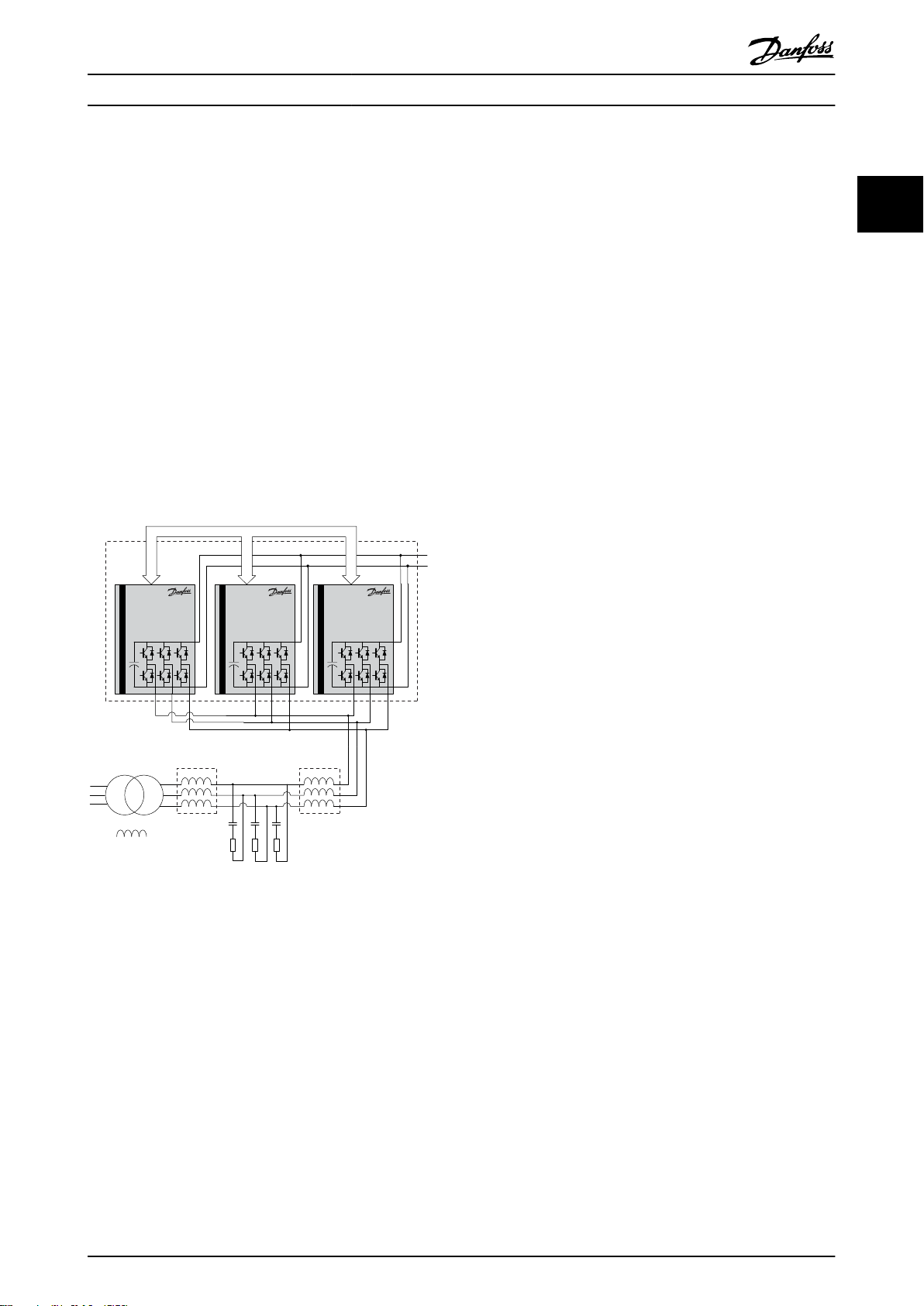
An Active Front End (AFE) is sometimes called an active
rectifier, in comparison with a passive rectifier such as the
diode bridge. The AFE consists of LCL filter and the
inverter unit.
WARNING
Touching the electrical parts may be fatal even after the
equipment is disconnected from the mains.
Before carrying out the maintenance, the frequency
converter must be disconnected from the mains. It will
avoid the electrical shock hazard.
Check the discharge time on the nameplate for the exact
waiting period. Otherwise wait at least 40 min.
6 Danfoss A/S © Rev. 05/2014 All rights reserved. MG33X402
The AFE main features are as follows:
sinusoidal input current and low harmonic
•
distortion in the mains
unity power factor
•
both rectifying and regenerating operation
•
constant regulated DC voltage
•
Illustration 2.1 shows the AFE system example.
At start-up, the AFE must detect the mains frequency and
phase to synchronize the operation.
Page 9
Transformer
AFE
Master Slave Slave
Control signals
130BA771.11
L
m
L
t
C
f
L
C
R
d
Safety Instructions and Gen... Operating Instructions
During the normal operation, the AFE DC-link voltage is
regulated to be constant. This means that the energy from
the decelerated motor is passed on to the mains as
regenerated electrical energy. A passive rectifier would
require a braking resistor to consume the surplus energy
as heat. The AFE is energy efficient for the application
where the motor deceleration is frequent. Also the brake
resistor space is saved.
The LCL filter allows the power flow. It also reduces the
ripple current of the fundamental frequency, switching
frequency, and their harmonics into the mains. A damping
resistor Rd is connected in series with the filter capacitor
Cf to stabilize the filter resonance.
The three inverter units are connected in parallel to
achieve the required power level. One AFE controller
regulates the three parallel-connected inverter units.
2 2
Illustration 2.1 Active Front End System Example
MG33X402 Danfoss A/S © Rev. 05/2014 All rights reserved. 7
Page 10
Crane System Design
Operating Instructions
3 Crane System Design
The cable length is calculated as the sum of all
3.1 Selection of Motor Voltage
33
The AFE system is designed to regulate a DC voltage of
630x1.08=680 V. 690 V motors are suitable for this system.
When the motors are used in the field weakening region
or with output filters, the motors with less than 650 V are
used.
3.1.1 Selection of AFE & LCL Filter
AFE systems are built up based on standard 690
•
V hardware.
Standard AFE hardware runs on 630 V mains
•
supply and DC-link voltage is 975 V.
Selection of AFE for Different
3.1.2
Applications
The frequency converter power size in the flux
•
application must be one or two sizes higher than
the application needed. Also, the frequency
converter should not be higher than two to
maintain a good resolution on current sensors.
The AFE electrical rating should be selected
•
based on the worst-case total power, including
the overload percentage, rather than a mere sum
of the motor power.
Example:
•
Hoist motors 500 kW @ 650 V - Hoist
drives 800 kW
Travel motors 8x50 kW @ 650 V - Travel
drive 500 kW
Trolley motors 4x55 kW @ 650 V Trolley drive 400 kW
AFE/LCL – 1,2 MW continuous, with a
175% overload for a maximum 1 min.
Selection of Output Filter (LC Filter)
3.1.3
The output filter is needed because of the long
•
motor cable configuration.
Output filters should be sized based on the
•
frequency converter's maximum output current.
The dU/dt filters can be used up to 100 m to
•
protect the motor. The sine-wave filters can be
used with any cable length (maximum of 1,000
m).
Above 150 m cable length it is recommended to
•
use a sine-wave filter.
•
parallel cables.
Filters must be designed to switching frequency
•
of the frequency converter. The resonance
frequency, f0, of the filter should be:
10×
f
out max
The resonant frequency must meet the following
•
equation, limited by the control frequency, f
f
con
f
<
0
6
Switching frequency [kHz]
1.5 3
2 4
2.5 5
3 6
3.5 7
4 4
5 5
6 6
7 7
Table 3.1 Frequencies
1) The control frequency is an internal hardware frequency.
Selection of Switching Frequency
3.1.4
It is recommended that the switching frequency of AFE
and motor drives shall be equal or an integer multiple of
each other.
Selection of LCL Filter
3.1.5
The AFE system is designed in conjunction with the
recommended Danfoss LCL filters in which the physical
size, power rating and electrical parameters of the filters
are optimized.
If non-Danfoss filters are used, system performance and
stability may be degraded.
Crane Cable Concept
3.1.6
To reduce the high frequency noise on the mains line and
to meet the EMC emission limits, the electromagnetic
coupling should be avoided and the following rules have
to be applied:
f
sw
≤
f
≤
0
3
:
con
Control frequency1) [kHz]
8 Danfoss A/S © Rev. 05/2014 All rights reserved. MG33X402
Page 11
Crane System Design
Operating Instructions
1. Use the shielded cable between the sine-wave
filter and frequency converter.
2. Keep the unshielded cable away from the mains
cable. The two cables should not be run in
parallel.
3. If the installation requires to route the motor
cables and mains cables in parallel, keep a
distance of at least 45 cm between the two
cables. Separate the cables by placing them in
different cable trays or in different sections of a
cable tray.
4. Use continuous cable trays and avoid “laddertype” cable trays.
5. Route the motor cable along the metallic
grounded conductors such as cable trays, rails
from the building structure, pipes, etc.
Grounding Concept
3.1.7
Do the common grounding between AFE and
•
motor drives.
The output filters and LCL should have low
•
impedance grounding to the AFE and motor
frequency drives.
Ensure low impedance between entire crane
•
construction and the cabinets and the
transformer.
Use only one connection to the transformer.
•
NOTICE
The door fan(s) is required on the Rittal cabinet to
remove the heat losses from the frequency converter
and other components inside the enclosure. The total air
flow required must be calculated and the appropriate
fan can be selected. Rittal Therm software can calculate
the cooling air flow volume. If the frequency converter is
the only heat generating source in the enclosure, the
minimum airflow required at an ambient temperature of
45 °C for the D3 and D4 frame sizes is 391 m3/h (230
cfm). The minimum airflow required at an ambient
temperature of 45 °C for the E2 frame size is 782 m3/h
(460 cfm).
Airflow
Table 3.2 shows the necessary airflow over the heat sink.
Enclosure
protection Frame size
IP54/NEMA 12 F1, F2, F3 and
F4
IP00/Chassis D3 and D4
E2 P400T7
E2 P500P560T7
* Airflow per fan. Frame size F contain multiple fans.
Table 3.2 Heatsink Air Flow
Door
fan(s)/Top fan
airflow
525 m3/h (309
cfm)*
255 m3/h (150
cfm)
255 m3/h (150
cfm)
255 m3/h (150
cfm)
Heatsink
fan(s)
985 m3/h (580
cfm)*
765 m3/h (450
cfm)
1105 m3/h
(650 cfm)
1445 m3/h
(850 cfm)
3 3
Cooling and Airflow
3.1.8
Cooling
The cooling air can be channeled through the air ducts at
the top and bottom of the unit, through the back of the
unit, or through the combination of the both methods.
Duct cooling
The duct cooling kit is used to install IP00/chassis D and Eframe frequency converters in the Rittal TS8 enclosure.
See Installation of Duct Cooling Kit in Rittal enclosures, for
further information.
Back cooling
The D and E frame frequency converters can be mounted
in the Rittal cabinet where the cabinet backplate has
cutout, through which the back-channel cooling is
available.
NOTICE
The ideal cooling air is clean and dry. When the cooling
air is from outside, the filter mats and long air inlet may
be considered to prevent the dirty air problem. When
the application environment is humid, consider the
condensation of the frequency converter which may
require the drain outlet.
NOTICE
The fan runs for the following reasons:
1. AMA
2. DC Hold
3. Pre-Mag
4. The frequency converter current exceeds 60%
of its nominal current rating.
5. The heat sink temperature exceeds its limit. The
limit depends on the power size.
When the fan is activated, it will run for a minimum of
10 min.
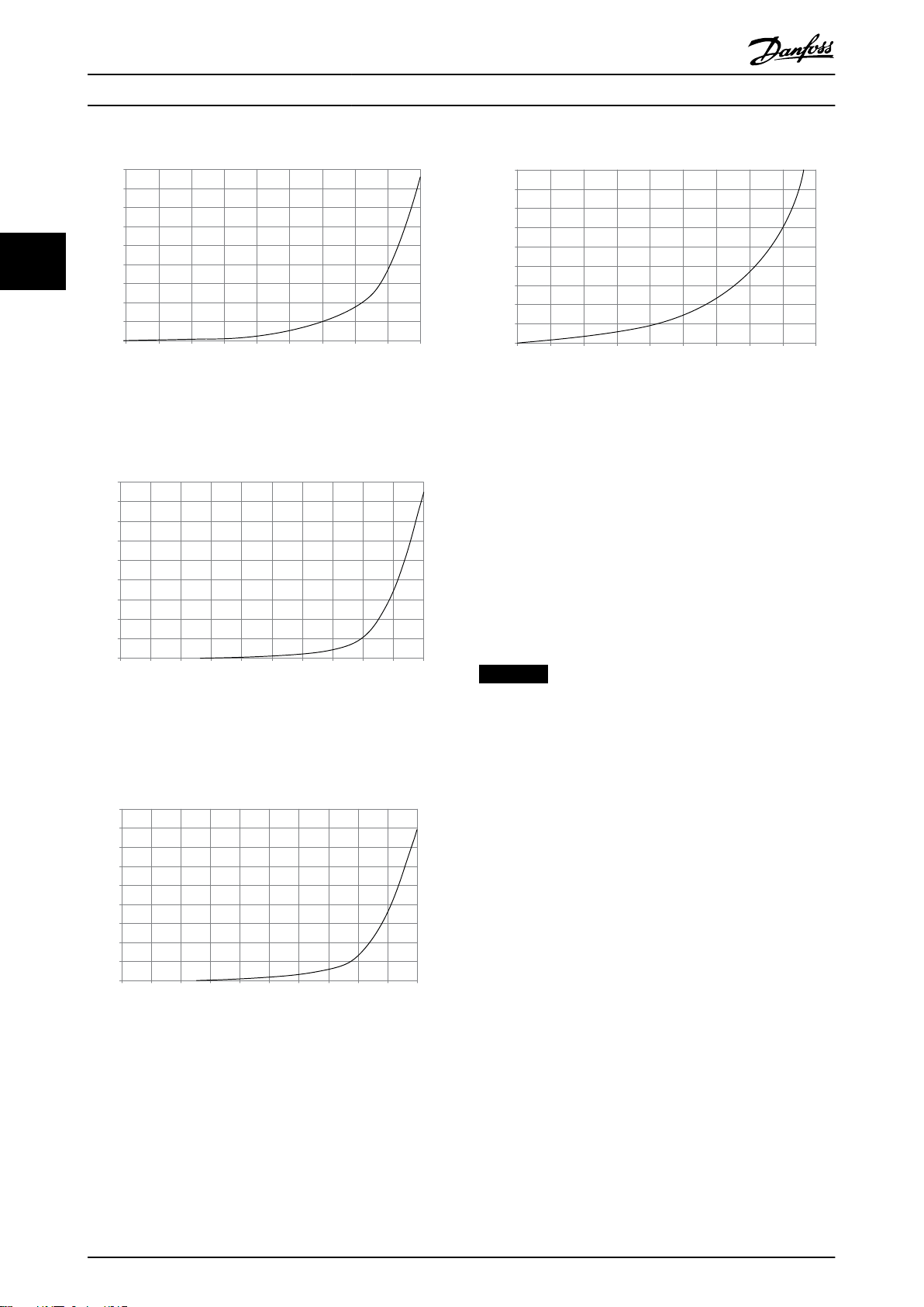
External ducts
If additional duct work is added externally to the Rittal
cabinet the pressure drop in the ducting must be
calculated. Use the charts below to derate the frequency
converter according to the pressure drop.
MG33X402 Danfoss A/S © Rev. 05/2014 All rights reserved. 9
Page 12
90
80
70
60
50
40
30
20
10
0
0 0.5 4.9 13 27.3 45.9 66 89.3 115.7 147
(%)
(Pa)
Pressure Increase
Drive Derating
130BB007.10
90
80
70
60
50
40
30
20
10
0
(%)
Drive Derating
0 0 0.1 3.6 9.8 21.5 43.4 76 237.5 278.9
(Pa)
Pressure Change
130BB010.10
147.1
90
80
70
60
50
40
30
20
10
0
(%)
Drive Derating
0 0.2 0.6 2.2 5.8 11.4 18.1 30.8 152.8 210.8
(Pa)
Pressure Change
130BB011.10
69.5
90
80
70
60
50
40
30
20
10
0
(%)
Drive Derating
0 25 50 75 100 125 150 175 225
130BB190.10
200
Pressure Change
Crane System Design Operating Instructions
33
Illustration 3.1 D frame derating vs. pressure change
frequency converter air flow: 450 cfm (765 m3/h)
Illustration 3.2 E frame derating vs. pressure change (small
fan), P355T7-P400T7
frequency converter air flow: 650 cfm (1105 m3/h)
Illustration 3.4 F1, F2, F3, F4 frame derating vs. pressure
change
frequency converter air flow: 580 cfm (985 m3/h)
Selection of Transformer
3.1.9
The output of the HT-transformer must be
•
specified for 630 V.
It is recommended to use 2 separate transformers
•
for 630 V and the 400 V and these transformers
should be physically separated. The 400 V
transformer must be close to or in the E-house to
have a short ground cable.
NOTICE
Danfoss reviews/evaluates the LCL filter design for each
application especially when the new transformer is used.
Illustration 3.3 E frame derating vs. pressure change (large
fan), P500T7-P560T7
frequency converter air flow: 850 cfm (1445m3/h)
10 Danfoss A/S © Rev. 05/2014 All rights reserved. MG33X402
Page 13
Crane System Design Operating Instructions
3.2 Assembling the Frequency Converter
System
3.2.1 Tools Required
Operating Instructions for the FC Series.
Metric socket set 7–19 mm
Socket extensions 1/4" drive size, 4", 6" and 12"
Torx driver set T8-T50
Torque wrench 0.675–19 Nm (6–168 in-lbs)
Needle nose pliers
Magnetic sockets
Ratchet
Hex wrench set
Screwdrivers Standard and Phillips
Table 3.3 Tools Required
Additional Tools Recommended for Testing
Digital volt/ohmmeter (rated for 1200 V DC)
Voltmeter
Oscilloscope
Clamp-on style ammeter
Test cable PN 176F8766
Signal test board PN 176F8437
Power supply: 500-1000 V DC, 250 mA to supply external power
to 4 power cards and the control card.
Power supply : 24 V DC, 2 A for external 24 V power supply.
Table 3.4 Additional Tools
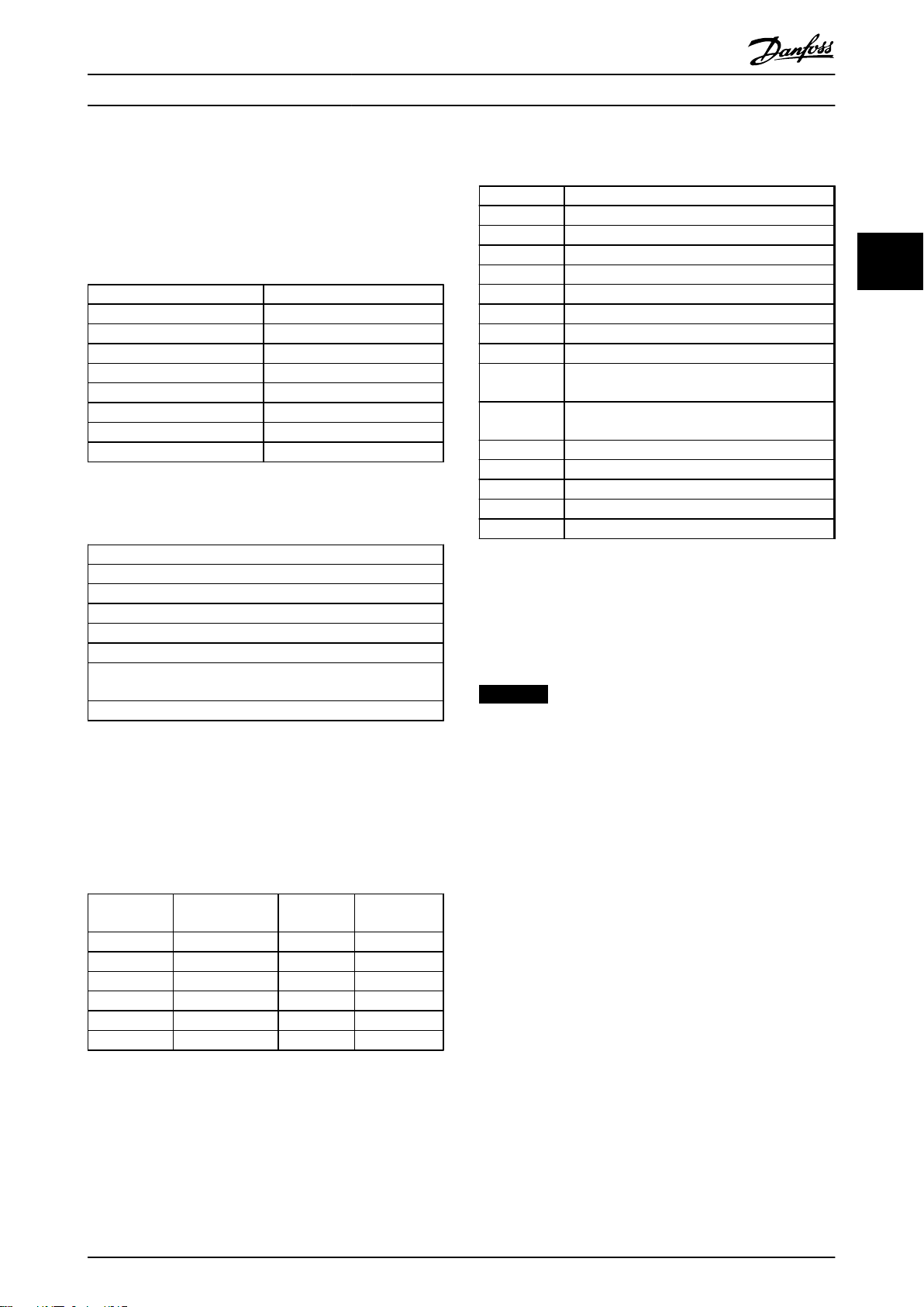
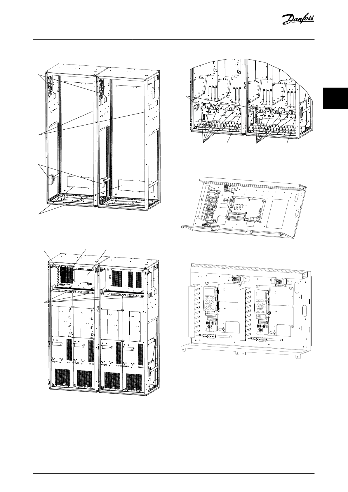
3.2.3
Exploded Views
Number Terminal and component description
1 Fan Voltage Supply (FVS)
2 Soft Charge Board (SC)
3 FVS Fuse (TB10)
4 SC Fuse (TB11)
5 Aux Fan Fuse
6 Fan Fuse
7 SMPS Fuse
8 Mains Terminals (R, S, T)
9 Aux Relay (TB12)
01 02 03 04 05 06
10 VSYNC (TB13) (Only for AFE Cabinet)
01-R, 02-S, 03-T
11 Control Card
12 MDCIC
13 Control Panel (Check the enlarged view)
14 DC Terminals (DC+ and DC-)
15 DC Bus Fuses
Table 3.6 Legend for Illustration 3.6 to Illustration 3.18
The rated voltage and maximum current magnitudes for
the AUX relay and VSYNC terminals are as follows:
AUX Relay: 240 V AC 2 A
VSYNC: 630 V 1 A
NOTICE
The control circuit including the control card terminal is
PELV isolated and it is also isolated from the power
circuit galvanically.
3 3
General Tightening Torque Values
3.2.2
Table 3.5 tabulates the tightening torque values. The
tightening toque values for the rectifier and IGBT modules
are referred to in the instruction within the spare kits.
Shaft size Driver size
Torx/hex
M4 T-20/7 mm 10 1.0
M5 T-25/8 mm 20 2.3
M6 T-30/10 mm 35 4.0
M8 T-40/13 mm 85 10
M10 T-50/17 mm 170 19
M12 18 mm/19 mm 170 19
Table 3.5 Torque Values
Torque [in-
lbs]
Torque [Nm]
MG33X402 Danfoss A/S © Rev. 05/2014 All rights reserved. 11
Page 14
130BA667.10
130BA664.10
9,10
11
12
130BT258.10
9 9
11
11
130BA663.10
1
2
8
2
4
13
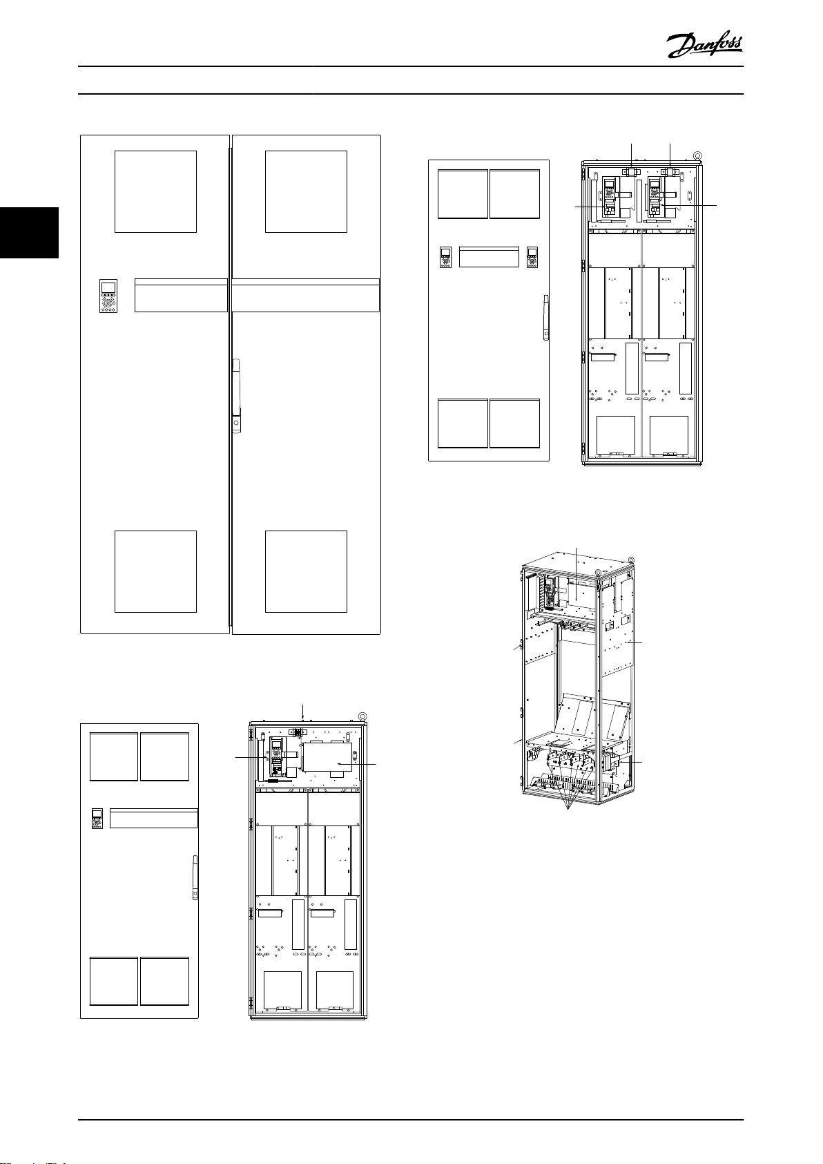
Crane System Design Operating Instructions
33
Illustration 3.7 Outside- and Inside View
Illustration 3.5 Front Door View
Illustration 3.8 800 mm Cabinet Skeleton View
Illustration 3.6 800 mm Cabinet Front Door and its Inside
Views (One Drive Case)
12 Danfoss A/S © Rev. 05/2014 All rights reserved. MG33X402
Page 15
130BA665.10
8
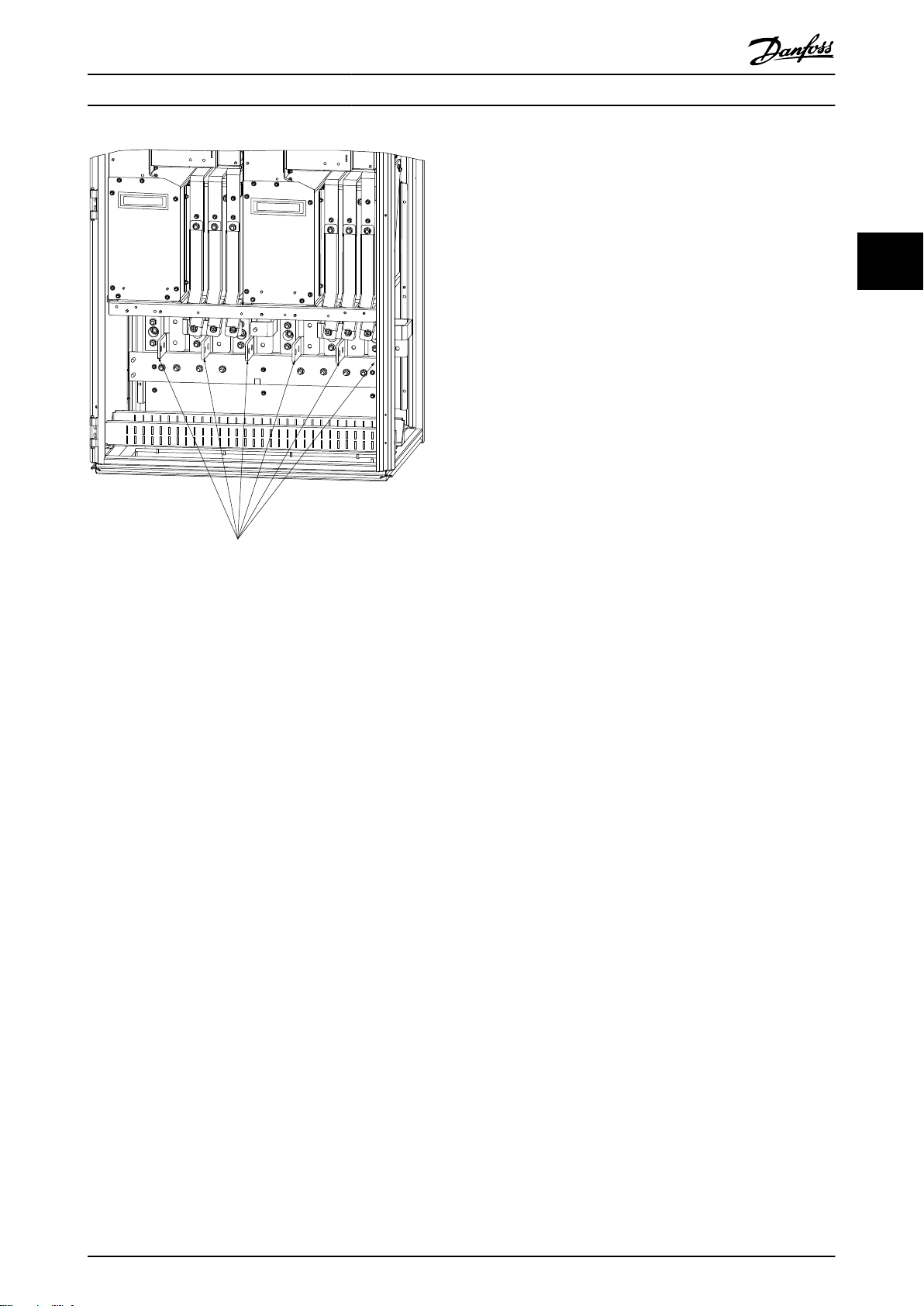
Crane System Design Operating Instructions
3 3
Illustration 3.9 800 mm Lower Front End View
MG33X402 Danfoss A/S © Rev. 05/2014 All rights reserved. 13
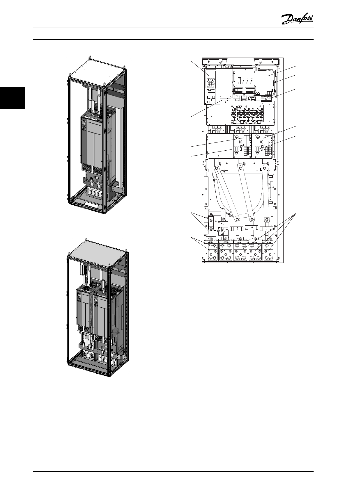
Page 16
1
3
3
8
4
2
5
6
7
4
13
130BA666.10
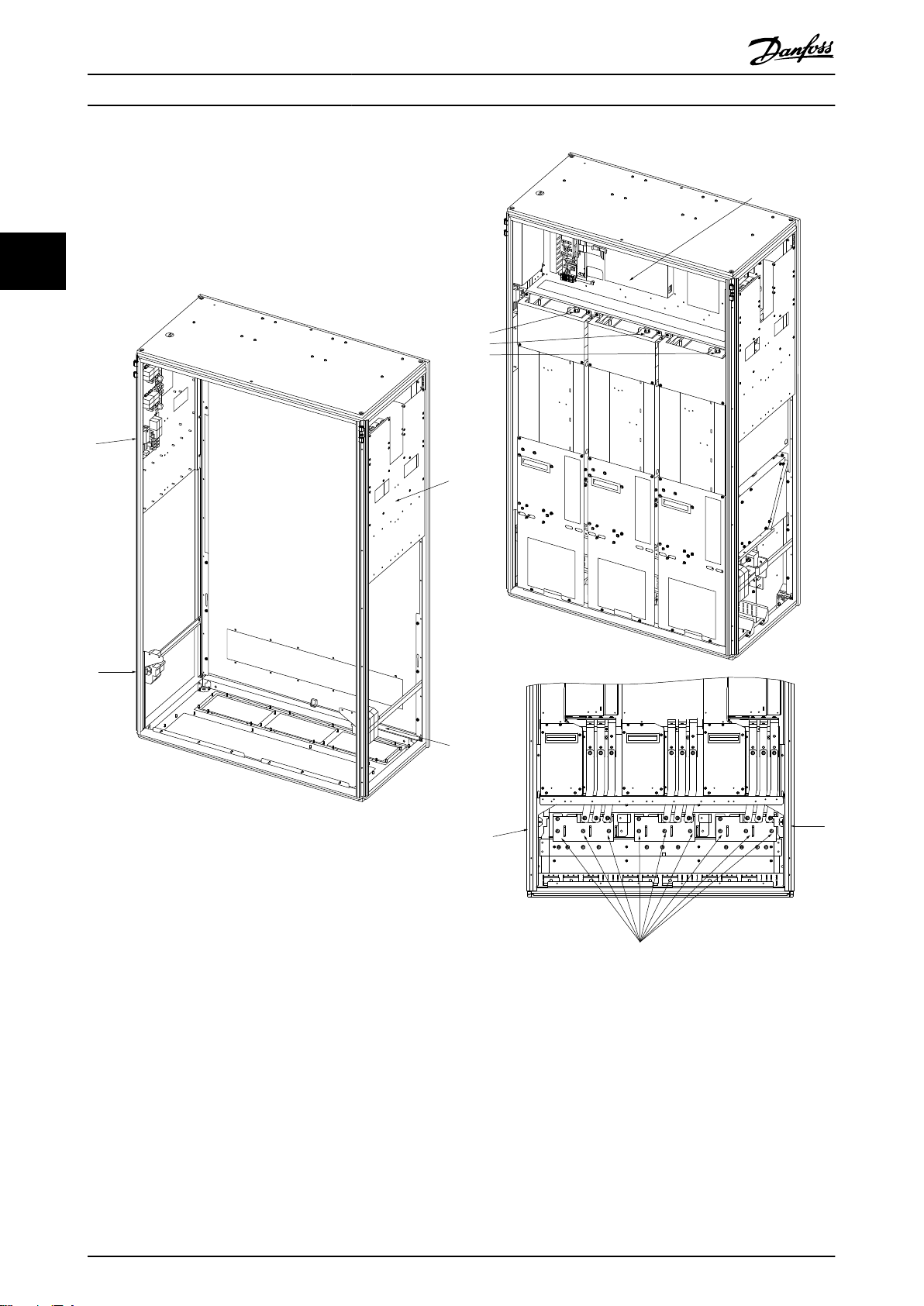
Crane System Design
Operating Instructions
33
Illustration 3.10 1200 mm Cabinet Exploded View
14 Danfoss A/S © Rev. 05/2014 All rights reserved. MG33X402
Page 17
1
2
3
4
130BD818.10
9,10
12
11
5, 6, 7
130BD819.10
130BD820.10
3
4
4
8
8
130BT254.10
130BT255.10
12
13
18
19
27
29
32
33
20
33
64
Life Stop
55
12
13
18
19
27
29
32
33
20
33
64
Life Stop
55
Crane System Design Operating Instructions
3 3
Illustration 3.13 1600 mm Cabinet Exploded View
Illustration 3.11 1600 mm Cabinet Exploded View
Illustration 3.14 One-drive Configuration Control Panel View
Illustration 3.15 Two Independent Drive Configuration Control
Panel View
Illustration 3.12 1600 mm Cabinet Exploded View
MG33X402 Danfoss A/S © Rev. 05/2014 All rights reserved. 15
Page 18
130BD836.10
130BD837.10
-C-
-C-
12
10
6, 7
2
4
8
11
9
1
3
15
14
130BD871.10
Crane System Design Operating Instructions
33
Illustration 3.16 600 mm Drive Cabinet
Illustration 3.18 AFE E-frame Drive Open View
Illustration 3.17 800 mm Drive Cabinet
16 Danfoss A/S © Rev. 05/2014 All rights reserved. MG33X402
Page 19
Crane System Design
Operating Instructions
3.2.4 MDCIC Connector Configuration
The MDCIC board has the four connectors. The ribbon
cables from the power units will be connected from FK100
to FK103.
For one power unit configuration, the part 176F9091 which
consists of the DC/DC converter and the ribbon cable is
connected to FK101. It generates an isolated 5 V from an
internal 24 V for the RS-485 communication.
FK100 (Master) FK102 (Slave 2)
FK101 (Slave 1) FK103 (Slave 3)
Table 3.7 MDCIC Port Layout
3.3 First Power Up/Commissioning Check
List
The following measurement equipment are recommended:
Voltage meter (1 kV AC/DC env. Cat III)
•
Current clamp min. 2 kA
•
Harmonic analyzer, only for commissioning
•
Check list
Check fan voltage supply (3x400 V).
•
Verify that system is not powered.
•
Verify the system is grounded to earth.
•
all AFEs and frequency converters
-
all motors
-
all filters
-
the whole crane construction
-
HT transformer
-
Check that there are no earth faults or short
•
circuits at the motor cables and motors.
Check that the DC discharge resistor is connected
•
right and not shorted.
Verify phase sequence and continuity for the
•
voltage sensing on the AFE as described below.
Make sure that power is not applied.
-
Manually close input contactor between
-
AFE and LCL filter.
Unplug the MK105 connector on the
-
MDCIC.
Measure MK105 of MDCIC harness to
-
the input phases.
Red wire of MK105 to phase R.
-
White wire of MK105 to phase
-
S.
Black wire of MK105 to phase
-
T.
-
All should be <0.2Ω.
Open the input contactor between AFE and LCL
•
filter.
Verify that the mains voltage is 630 V RMS and
•
balanced.
Apply power to the LCL filter and verify that the
•
rms current magnitude measured between the
line and delta connection point is approximately
same as the value using the following formula:
630×314 ×C×3
i
=
capacitance, delta value.
Leave the AFE main contactors open and disallow
•
the AFE start signal in the PLC.
Soft charge the system but do not enable the
•
main contactor.
Let the softcharge circuit active for about 5min.
•
Check the voltage at the AFE Mains side when
•
the AFE is powered up by softcharge. The voltage
between all phases should be 0 V. Also the
voltage between the phases L1/L2/L3 and earth
should be 0 V. Please call Danfoss service if you
can measure a voltage greater then 10 V here.
Do not switch on the mains contactors if you
measure a voltage more than 10 V here.
Verify that the LCP readings for the DC-link
•
voltage from all the AFE and inverter drives are
within ±2% of the value measured with the
voltage meter. The estimated DC-link voltage
value at 630 V mains voltage with no load is as
follows:
890
V
+5 / − 10% =
DC
= 630× 1,414+ 5 / −10%
Download all the AFE and frequency converter
•
settings with MCT 10 Set-up Software.
1. Capacitance value of the LC filter in the
2. Set the right LCL filter values in the AFE,
3. Set the right mains values in the AFE.
4.
5. Total system capacitance par. 7-60 must
, where C is the LCL filter
3
V
mains_LL_RMS
inverter drive must be star equivalent.
the capacitance value of the LCL filter
shall be entered as delta equivalent.
Parameter group 4-** Output Limits AFE
– use factory settings.
be programmed with a sum of the DClink capacitance x 0,9.
× 2+5 / −10 %
3 3
MG33X402 Danfoss A/S © Rev. 05/2014 All rights reserved. 17
Page 20

Crane System Design
6.
Use parameter group 7-** Controllers as
follows:
Parameter 7-61 DC-Link
•
Reference is 975 V.
Parameter 7-62 DC-Link PI
•
33
Switch Crane off.
•
Program the PLC to the normal start-up
•
sequence.
Switch Crane on.
•
The AFE starts, but not any of the inverters, and
•
verify that the AFE and inverter LCP readings are
975 V DC and that they are within ±2% of a
calibrated voltage meter.
Check if all fans are running after closing the
•
mains contactor.
Start checking inverters and motors.
•
Save all parameter settings with MCT 10 Set-up
•
Software.
For the crane commissioning, measure THDu and
•
THDi of the 630 V and 400 V terminals and
document the results in the commissioning
certificate.
Verify that the THD levels of the 400 V terminal
•
are complied to EN 61000-3 or other country
specified harmonic requirements.
3.4
E-House Design
Proportional Gain (Kp) is
calculated internally based on
the power size and DC
capacitance in parameter 7-60
DC-Link Total Capacity.
Recommend to use the default
value. The wrong setting could
cause the unstable DC voltage
regulation.
Parameter 7-63 DC-Link PI
•
Integral Time (Ti) is 5 ms in
default.
3.4.1 Cables between AFE and LCL Filters
The cables should be as short as possible.
•
The connection must be made with shielded
•
cables.
The synchronization voltage cable which is connected to
the AFE-MDCIC board MK105 must be separated from all
power cables. The distance needs to be at least 50 cm
from other power cables.
3.4.2
Cables to the Damping Resistors
Operating Instructions
3.5
Test with the Real System Transformer
and Motors
3.5.1 Re-program the Frequency Converter
Parameters
Set the mains voltage, mains frequency, the
•
transformer values, LCL filter values, and DC
capacitance.
3.6 On-site Final Test
3.6.1 Change Parameters to Actual
Set actual cable length.
•
Check encoder wiring and encoder direction.
•
Optimize ramp time shapes.
•
Save parameter settings in the LCPs.
•
Run with Full Load
3.6.2
Check that AFE input voltage is stable. The
•
voltage waveform does not need to be
sinusoidal.
Check that DC-link voltage is stable.
•
3.7
AFE Emergency and Restore Procedures
Chapter 3.7.1 Emergency Run when One Slave Unit is
Damaged to chapter 3.7.4 Restoration after Master Unit is
Repaired describe how to set up an emergency run and
how to restore the drive for the case where one of the
three units are damaged. Chapter 3.7.5 Emergency Run
When More Than One Unit is Damaged describes the case
where the multiple units are damaged.
Emergency Run when One Slave Unit
3.7.1
is Damaged
NOTICE
The mains synchronization voltage is always connected
to the MDCIC board. Make sure that the mains power
switch is off before opening the frequency converter
cabinet.
NOTICE
The power is reduced to two thirds of the original.
1. Switch Crane off.
2. Switch the circuit breaker in front of the
damaged AFE power unit off.
3. Check the DC-link voltage with a voltage meter at
the terminals before and after the DC fuses.
The cables should be as short as possible.
18 Danfoss A/S © Rev. 05/2014 All rights reserved. MG33X402
Page 21

Crane System Design
Operating Instructions
NOTICE
Do not touch until the DC voltage is below 10 V.
4. Disconnect the DC-link fuses of the damaged
power unit and AC connection.
5. Disconnect the softcharge connector on the
softcharge board of the damaged power unit.
6. Disconnect the ribbon cable, from the damaged
AFE power unit, on the MDCIC card.
7. If the removed connector is at Inverter 2 position,
move the ribbon cable at Inverter 3 position to
Inverter 2.
8.
Turn the key switch to AFE emergency mode.
9. Switch Cane on.
10. Check on the AFE LCP if it is in set-up 2. The setup shift at the AFE is done with terminal 32 at
AFE control card. Terminal 32 = 0 means set-up 1,
Terminal 32 = 1 means set-up 2.
11. A warning 78 (power unit set-up) may come up
at the AFE LCP.
12. Switch Crane off.
13. Wait at least 20 s. All LCPs must be completely
off.
14. Switch Crane on.
15. The warning 78 disappears and the warning 77
(Reduced power mode) appears on LCP.
16. The AFE can run with two units with a reduced
power.
Restoration after Slave Unit is
3.7.2
Repaired
1. Switch Crane on but do not run any frequency
converter.
2.
Turn the key switch to AFE normal mode.
3. A warning 78 appears on AFE LCP.
4. Check on the AFE LCP if it is in set-up 1. The setup shift at the AFE is done with terminal 32 at
AFE control card. Terminal 32 = 0 means set-up 1,
Terminal 32 = 1 means set-up 2.
5. Switch Crane off.
6. Check the DC-link voltage with a voltage meter at
the terminals before and after the DC fuses.
NOTICE
Do not touch until the DC voltage is below 10 V.
7. Bring back the ribbon cables on the MDCIC card
in the original set-up (AFE Master to Inverter 1,
AFE Slave left to Inverter 2, AFE Slave right to
Inverter 3).
8. Connect the softcharge connector on the
softcharge board.
9. Connect the DC-link fuses and AC connection.
10. Switch on the circuit breaker in front of the AFE.
11. Switch Crane on.
12. The AFE runs now with all 3 power units.
3.7.3 Emergency Run when Master Unit is
Damaged
NOTICE
The power is reduced to two thirds of the original.
1. Switch Crane off.
2. Switch the circuit breaker in front of the
damaged AFE power unit off.
3. Check the DC-link voltage with a voltage meter at
the terminals before and after the DC fuses.
NOTICE
Do not touch until the DC voltage is below 10 V.
4. Disconnect the DC-link fuses of the damaged
power unit and AC connection.
5. Disconnect the softcharge connector on the
softcharge board of the damaged power unit.
6. Disconnect the ribbon cable from the Inverter 1
position at the MDCIC.
7. Unplug the ribbon cable at Inverter 3 position on
the MDCIC card and plug it at Inverter 1 position.
8. Plug this ribbon cable (what you plugged out
from Inverter 3) on the connector Inverter 1. Now
the right power unit will be the AFE Master.
9.
Turn the key switch to AFE emergency mode.
10. Switch Crane on.
11. Check on the AFE LCP if it is in set-up 2.
12. A warning 78 may appear on AFE LCP.
13. Switch Crane off.
14. Wait at least 20 s. All LCPs must be completely
off.
15. Switch Crane on.
16. The warning 78 disappears and the warning 77
appears on LCP.
17. The AFE can run with two units with a reduced
power.
3 3
MG33X402 Danfoss A/S © Rev. 05/2014 All rights reserved. 19
Page 22

Crane System Design Operating Instructions
3.7.4 Restoration after Master Unit is
Repaired
1. Switch Crane on but do not run any frequency
converter/motor.
2.
33
Turn the key switch to AFE normal mode.
3. A warning 78 appears on AFE.
4. Check on the AFE LCP if it is in set-up 1 (see
attached file LCP.pdf). The set-up shift at the AFE
is done with terminal 32 at AFE control card.
Terminal 32 = 0 means set-up 1, Terminal 32 = 1
means set-up 2.
5. Switch Crane off.
6. Check the DC-link voltage with a voltage meter at
the terminals before and after the DC fuses.
3. Power up.
4. Power cycle.
NOTICE
Do not touch until the DC voltage is below 10 V.
7. Bring back the ribbon cables on the MDCIC card
in the original set-up (AFE Master to Inverter 1,
AFE Slave left to Inverter 2, AFE Slave right to
Inverter 3).
8. Connect the softcharge connector on the
softcharge board.
9. Connect the DC-link fuses an AC connection.
10. Switch on the circuit breaker in front of the AFE.
11. Switch Crane on.
12. The AFE runs now with all 3 power units.
Emergency Run When More Than
3.7.5
One Unit is Damaged
When multiple units are damaged, an emergency run with
a minimum of one unit can be performed. The procedure
of setting up the emergency run and restoring from the
emergency run can be referred to in
chapter 3.7.1 Emergency Run when One Slave Unit is
Damaged to chapter 3.7.4 Restoration after Master Unit is
Repaired.
The following issues are considered:
1. In an emergency run, the door fan may not be in
operation. It is recommended that the emergency
configuration is only for a temporary usage.
2. An emergency run may cause the overcurrent
alarm at start-up because the start-up current
may be high for the number of units used. The
switching frequency (parameter 14-01 Switching
Frequency) may need to be increased from 1.5
kHz to 2 or 2.5 kHz.
3.8
Manual Shut Down Sequence
Stop all motor drives.
•
switch off the AFE start signal.
•
Open the mains contactor
•
Switch off the HT transformer if necessary
•
In emergency, command the AFE to stop and
•
open the AFE contactor, or pull the safe stop and
open the AFE contactor.
(176F9091) needs to be connected at
FK101 to have the RS-485 communication.
3a The warning message W78 (Power Unit
Setup) appears on LCP.
3b
Change the number of the units in
parameter 14-59 Actual Number of
Inverter Units.
4a The warning message W77 (Reduced
Power Mode) appears on LCP.
4b The power is reduced to the original
power multiplied by the number of
active units over the original number of
the units.
The key procedure of an emergency run is as follows:
1. Disconnect AC and DC sides of the damaged
units.
2. Change the connector position at MDCIC.
2a The ribbon cables at the MDCIC are
connected from FK100 (Master)
following FK101, FK102, and FK103. You
do not skip the terminal sequence.
2b You can go down to one unit. When
one master unit is used, the part
20 Danfoss A/S © Rev. 05/2014 All rights reserved. MG33X402
Page 23
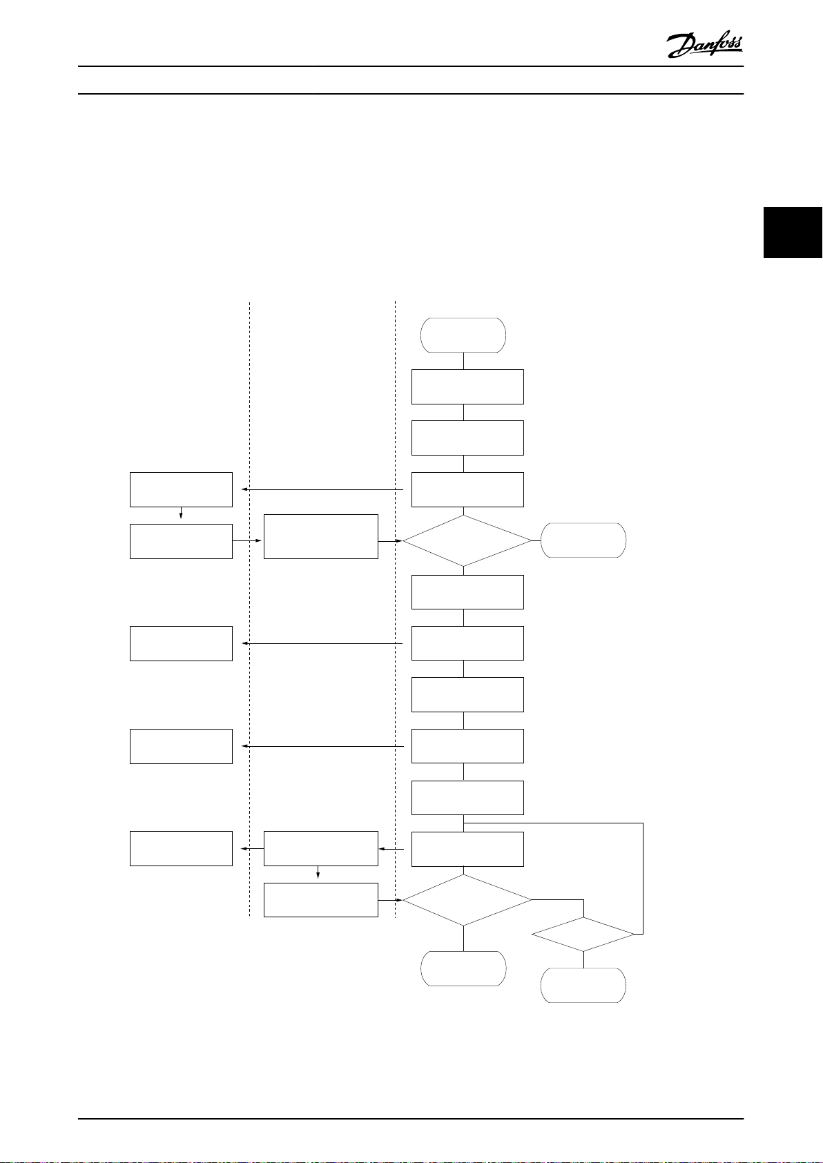
Auxiliary Hardware
Actions
AFE Drive Control PLC
: Assume that the AFE contactors
and SC contactor are open
prior to this start-up sequence.
Start-up Sequence
Crane ON
Contactor LCL cabs ON
2 sec Delay
Send close signal to
the SC contactor.
Receive "Soft Charge
Ready" signal within
20sec?
Protection Mode
due to the Start-up
Failure
No
Wait for 1 second
to have the DC capacitors
charged further.
Yes
Send the open signal
to the SC contactor.
Wait for 1 second
to make sure that the
S/C contactor is open.
Send the close signal
to the AFE contactors.
Wait for 0.5 second
to have the DC capacitors
charged fully.
Send the "Run"
signal to the AFE drive.
Receive "DC-Link
on Ref" signal from
AFE within 5 sec?
End of Start-up
Sequence
No
No
Yes
Yes
Protection Mode
due to the Start-up
Failure
3rd Try?
:The waiting period can be substituted
by the contactor status signal.
: Assume that the AFE contactors
are fully engaged within 2seconds.
:The waiting period can be substituted
by the contactor status signal.
: Assume that the SC contactor is
disengaged within 0.5sec.
The DC capacitor discharge
is negligble.
130BA783.12
Abbreviations:
AFE: ACtive Front End
CC: Control Card
PC: Power Card
PLC: Programmable Logic Controller
SC: Soft Charge
When the DC voltage is within
the target range, "DC-link on
Ref" signal is on.
The AFE drive is active.
DC voltage is going
up to the desired level.
The AFE contactors
are closed.
The SC contactor
is open.
Charge the DC bus
through the SC circuit.
The SC contactor
is closed.
When the PC becomes
active, "Soft Charge Ready"
signal is ON.
Crane System Design Operating Instructions
3.9 Start-up Sequence
Illustration 3.19 shows the typical AFE start-up sequence flow chart. The flow chart describes the interaction among Auxiliary
Hardware, AFE Frequency Converters, and Liebherr Control PLC. The arrowed lines indicate the flow of the actions. The
Liebherr PLC expects to receive the “Control Ready” and “Ready” signals from the AFE frequency converter and it will send
“Run” signal to AFE frequency converter. The waiting periods and the number of tries are tentative. The “Control Ready”
signal is on when the power in Control Card is on. The meaning of the "Ready" signal in the AFE frequency converter is
different from the one in the standard frequency converter. The “Ready” signal in the AFE frequency converter is on when
the DC voltage is boosted to the level where the AFE regulation is enabled.
3 3
Illustration 3.19 Start-up Sequence Flow Chart
MG33X402 Danfoss A/S © Rev. 05/2014 All rights reserved. 21
Page 24

Send Open signals to
the AFE and Mains
contactors.
AFE/Inverter DrivesAuxiliary Hardware
Actions
Control PLC
130BA775.11
End of Stop
Sequence
Stop Sequence
Wait for 1sec.
Send INV Stop signals
to all the inverters
All the inverters control
to reduce the speed
to zero, if it is not zero.
Send AFE Stop signals
to the AFE.
AFE is deactive.
DC voltage level is
down to zero
DC voltage level
is reduced.
Open the contactor.
The motor speed is
reduced to zero.
"Running" signal is o
when the speed is zero.
"Running" o?
Yes
No
Wait for 5min?
No
Protection Mode
Yes
The DC capacitor can be discharged
with the external resistor, which
expedites the discharge process.
: The wait period is tentative.
Crane System Design Operating Instructions
3.10 Shut-down Sequence
It is recommended to send a STOP signal to the AFE before shutting down the power.
33
Illustration 3.20 Shut-down Sequence Flow Cart
22 Danfoss A/S © Rev. 05/2014 All rights reserved. MG33X402
Page 25

Fuse
Fuse
Fuse
Fuse
Fuse
Fuse
Fuse
Fuse
Inv #1
Inv #2
Inv #3
Inv #4
RST
LCL Filter
Fuse
Disconnect
Main PC
Sub PC1
Sub PC2
CT
CT
CT
gate signals
* Control gate signals
* Detect currents.
* Measure DC voltage.
* Control fans.
* Control gate signals
* Detect currents.
* Control fans.
* Control gate signals
* Detect currents.
* Control fans.
gate signals
gate signals
444444
MDCIC
FC302
CC
44
MDCIC Functions:
* Distribute the gate signals.
* Combine the current signals and
send it as a total rec current.
Detect the overcurrent (IMAX1)
per module per phase.
* Detect the main voltage phase to
synchronize AFE (Only for AFE)
Voltage
Detection
Fan
Volt
Soft
Charge
Soft
Charge
AFE #3
Contactor
Fuse:
AFE #2
Contactor
AFE #1
Contactor
Soft
Charge
Soft
Charge
Soft
Charge
Soft
Charge
SC Wire Fuse
Fuse:
Fuse:
IM
Trolley
Travel
Fuse
Fuse
Fuse
Fuse
Fuse
Fuse
PC
PC
PC
PC
Soft
Charge
Fan
Volt
Fan
Volt
Fan
Volt
Fan
Volt
Fan
Volt
Fan
Volt
Fan Volt Wire Fuse
SC Contactor
Hoist Master
Abbreviations:
AFE: Active Front End
CC: Control Card
MDCIC: Multi-Drive Control
Interface Card
PC: Power Card
Fan Volt Supply
400V Contactor
400V
630V
Boom
Switch
IM
Hoist Master
IM
IM
IM
130BA683.10
How to Install Operating Instructions
4 How to Install
This chapter covers mechanical and electrical installations to and from power terminals and control card terminals.
4.1 Overall Typical Frequency Converter Configuration
4 4
Illustration 4.1 Typical System Overview
MG33X402 Danfoss A/S © Rev. 05/2014 All rights reserved. 23
Page 26

130BB639.10
A
B
How to Install Operating Instructions
The typical 1.2 MW LCL filter components are described
below:
1. Lc choke 100 uH
2. Lm choke 29 uH
3. Capacitor 10x 40 uF in delta, 30 pieces
4.
Resistors 90 mΩ 4000 W, 3 pieces
Transportation and Unpacking
4.2.3
Illustration 4.2 and Illustration 4.3 show the front and side
views of the frequency converter, shipping crate, respectively.
The unpacking procedure is as follows:
4.2 Pre-installation
44
4.2.1 Planning the Installation Site
Before performing the installation it is important to plan
the installation of the frequency converter. Neglecting this
may result in extra work during and after the installation.
Select the best possible operation site by considering the
followings:
Ambient operating temperature
•
Installation method
•
Cooling method
•
Position of the frequency converter
•
Cable routing
•
Power source supply configuration
•
Motor current rating with respect to the
•
frequency converter maximum current magnitude
Fuse arrangement, either built-in fuses or the
•
properly rated external fusees
Receiving the Frequency Converter
4.2.2
1. Remove clips from one long side panel (A) and all
around the top.
2. Remove the long side panel (A).
3. Remove the top panel (B).
4. Remove clips from one short side panel (C).
5. Remove the short side panel (C)
6. Remove the rest of the clips.
7. Remove the final two panels.
NOTICE
The package includes the plinth at the bottom of the
frequency converter. The plinth allows proper cooling of
the frequency converter during the shipment.
When receiving the frequency converters, please inspect
the frequency converters for any damage which may occur
during the transportation. When the damage is noticed,
please contact the shipping company immediately to claim
the damage and let Danfoss know the situation to work
for the corrective action.
Illustration 4.2 Package Front View
24 Danfoss A/S © Rev. 05/2014 All rights reserved. MG33X402
Page 27

130BB640.10
C
How to Install Operating Instructions
4 4
Illustration 4.3 Package Side View
MG33X402 Danfoss A/S © Rev. 05/2014 All rights reserved. 25
Page 28

F1
1
F3
2
130BA658.10
1
F2
2
130BA659.10
F4
How to Install Operating Instructions
4.2.4 Lifting
Illustration 4.4 and Illustration 4.5 show the main load carrying points (1 and 2 in the illustrations) of the F-frame cabinets.
Lift the cabinets with all the lifting eyes and/or use a bar to avoid bending the lifting holes of the frequency converters. The
same principle is applied for the AFE cabinets.
44
Illustration 4.4 Main Load Carrying Points
Illustration 4.5 Main Load Carrying Points
NOTICE
The lifting cable angle should be 60° or greater. The spreader bar is an acceptable way of lifting. A spreader bar is an
acceptable way to lift the F Frame.
26 Danfoss A/S © Rev. 05/2014 All rights reserved. MG33X402
Page 29

ADD 3MM
BETWEEN
TWO CABINET
TO ACCOUNT
FOR GASKET
ADD 3MM
BETWEEN
TWO CABINET
TO ACCOUNT
FOR GASKET
1296.0
ALL CABINET
2003.4
ALL CABINET
597.0 797.0
65.5
0.0
CABINET
BACK
WALL
CABINET
BACK
WALL
CABINET
BACK
WALL
73.0
338.4
540.5
61.1
CABINET FRAME 0.0
68.8
536.0
61.0
CABINET FRAME 0.0
65.5
0.0
140.8
392.7
426.7
678.7
736.0
102.0
695.0
2X 81.4
294.0
2X 219.4
493.5
540.5
CABLE
OPENING
CABLE
OPENING
CABLE
OPENING
AIR INLET
OPENING
AIR INLET
OPENING
AIR INLET
OPENING
AIR INLET
OPENING
AIR INLET
OPENING
AIR INLET
OPENING
2078.4
ALL CABINET
WITH LIFT
BRACKET
1197.0
605.6
635.2
65.5
0.0
61.0
CABINET FRAME 0.0
140.8
430.8
464.8
754.7
788.7
1078.7
89.7
1084.0
1136.0
3X 81.4
3X 222.8
294.0
493.5
540.5
BACK CHANNEL
AIR IN
CABINET
AIR OUT
CABINET
AIR IN
600MM CABINET
BOTTOM VIEW
800MM CABINET
BOTTOM VIEW
1200MM CABINET
BOTTOM VIEW
SEE VIEW A
VIEW A
BACK CHANNEL
AIR OUT
X
130BA661.10
1597.0
2078.4
CABLE
OPENING
AIR INLET
OPENING
2X 61.0
2X 102.0
2X 695.0
2X 736.0
2X 678.7
2X 426.7
2X 392.7
2X 140.8
CABINET FRAME 0.0
0.0
CABINET
BACK
WALL
4X 65.6
4X 81.4
4X 219.4
2X 294.0
2X 493.5
4X 540.5
AIR INLET
OPENING
AIR INLET
OPENING
AIR INLET
OPENING
CABLE
OPENING
130BD821.10
How to Install Operating Instructions
4.2.5 Mechanical Dimensions
4 4
Illustration 4.6 Dimensions
Illustration 4.7 Dimensions 1600 mm Cabinet
MG33X402 Danfoss A/S © Rev. 05/2014 All rights reserved. 27
Page 30

DOOR SWING
583.5591.5
783.5
583.5
AIR OUTLET
OPENING
114.0
0.0
122.0
298.5
475.0
483.0
415.5
0.0
423.5
567.5
575.5
BLOCKED
600MM CABINET
98.5
0.0
113.0
269.3
281.9
800MM CABINET 1200MM CABINET
BLOCKED
BLOCKED
96.7
0.0
91.0
366.4
422.4
681.9
706.0
AIR OUTLET
OPENING
98.5
0.0
113.0
269.3
281.9
101.1
0.0
99.7
395.1
462.7
759.2
826.8
1074.7
1093.7
130BA662.10
AIR OUTLET
OPENING
How to Install Operating Instructions
44
Illustration 4.8 Door Swing View and Back View
28 Danfoss A/S © Rev. 05/2014 All rights reserved. MG33X402
Page 31

130BD822.10
0.0
2X 98.5
2X 113.0
2X 269.3
2X 281.9
0.0
2X 91.0
2X 96.7
2X 366.4
2X 422.4
2X 681.9
2X 706.0
2X 783.5
2X AIR OUTLET
OPENING
BLOCKED BLOCKED
How to Install Operating Instructions
4 4
Illustration 4.9 1600 mm Cabinet Door Swing View
MG33X402 Danfoss A/S © Rev. 05/2014 All rights reserved. 29
Page 32

130BA445.10
225
64
1320
585
269
156
23
25
498
539
1547
1502
160
1043
14
184
184
184
139
304
2X13
(2.5)
(23.0)
(52.0)
(6.2)
(19.5)
(10.6)
(21.2)
(60.9)
(5.5)
(12.0)
(7.3) (7.3)
(0.5)
(1.5)
120
(4.7)
25
(1.0)
(59.1)
(41.1)
(6.3)
(8.9)
225
(8.9)
(1.0)
25
(1.0)
(0.9)
27
(1.0)
13
(0.5)
E2
D
E
D
E
IP00 / CHASSIS
How to Install Operating Instructions
44
Illustration 4.10 Dimensions E-frame IP00 Drive
30 Danfoss A/S © Rev. 05/2014 All rights reserved. MG33X402
Page 33

How to Install Operating Instructions
4.2.6 Weight Information
Crate
length
Table 4.1 Weight Based on Shipping Package Crate Size
Crate weight Cabinet weight Cabinet content
weight
[mm] [kg] [lbs] [kg] [lbs] [kg] [lbs] [kg] [lbs]
600 120 252 57 126 159 351 336 729 Cabinet and D frame frequency converter
800 130 273 76 168 306 675 512 1116 Inverter modules Qty. 2
1200 160 336 115 253 459 1012 734 1601 Inverter modules Qty. 3
1200 160 336 115 253 318 701 593 1290 600 mm cabinet qty. 2, D vrame
1600 260 546 153 337 612 1349 1025 2232 2 x 800 mm cabinet with inverter modules
2000 320 672 191 421 765 1687 1276 2780 1200 mm cabinet with inverter modules
2400 380 798 229 505 918 2024 1527 3327 2 x 1200 mm cabinet with inverter
2800 440 924 267 590 1071 2361 1778 3875 1200 mm cabinet with inverter modules
Total package
weight
Package contents
frequency converters qty. 2
qty. 2, 1600 mm cabinet with inverter
modules qty. 4
qty. 3, 800 mm cabinet with inverter
modules qty. 2
modules qty. 3, 1600 mm cabinet with
inverter modules qty. 4 800 mm cabinet
with inverter modules qty. 2
qty. 3, 2 x 800 mm cabinet with inverter
modules qty. 2
4 4
MG33X402 Danfoss A/S © Rev. 05/2014 All rights reserved. 31
Page 34

122.5 [4.82]
.0 [.00]
178.0 [7.01]
233.5 [9.19]
363.5 [14.31]
419.0 [16.50]
474.5 [18.68]
722.5 [28.44]
778.0 [30.63]
833.5 [32.82]
963.5
[37.93]
1019.0
[40.12]
1074.5
[42.30]
1382.0 [54.41]
1452.0 [57.17]
1522.0 [59.92]
1737.5 [68.41]
1807.5 [71.16]
1877.5 [73.92]
2093.0 [82.40]
2163.0 [85.16]
2233.0 [87.91]
2581.9 [101.65]
2641.9 [104.01]
2701.9 [106.37]
2906.9 [114.44]
2966.9 [116.81]
3026.9 [119.17]
297.5 [11.71]
.0
[.00]
328.3
[12.93]
.0
[.00]
380.3 [14.97]
252.1 [9.93]
.0 [.00]
127.5 [5.02]
265.6 [10.46]
300.1
[11.82]
349.1
[13.74]
383.6
[15.10]
432.6
[17.03]
467.1 [18.39]
865.6[34.08]
900.1
[35.44]
949.1
[37.37]
983.6
[38.72]
1032.6
[40.65]
1067.1[42.01]
1365.1 [53.75]
1480.1 [58.27]
1595.1 [62.80]
1729.8 [68.10]
1844.8 [72.63]
1959.8 [77.16]
2094.4 [82.46]
2209.4 [86.99]
2324.4 [91.51]
2553.3 [100.53]
2668.3 [105.05]
2783.3 [109.58]
2906.2 [114.42]
3021.2 [118.95]
3136.2 [123.47]
600MM CABINET
TROLLEY/
TRAVEL
U,V,W
1200MM CABINET
AFE
R,S,T
800MM CABINET
HOIST 1&2
UVW
224.8
[8.85]
.0
[.00]
395.1 [15.56]
EARTH
GROUND BUS
(AFE/HOIST 1&2)
FASTENER TORQUE: M10 19 NM (14 FT-LB)
+DC/118 -DC/117
CH22
FASTENER TORQUE: M10 19 NM (14 FT-LB)
+DC/118 -DC/117
FASTENER TORQUE: M10 19 NM (14 FT-LB)
U/T196 V/T2 97 W/T3 98
FASTENER TORQUE: M10 19 NM (14 FT-LB)
U/T196 V/T2 97 W/T3 98
FASTENER TORQUE: M10 19 Nm (14 FT-LB)
R/L1 91 S/L2 92 T/L3 93
FASTENER TORQUE: M10 19 Nm (14 FT-LB)
R/L1 91 S/L2 92 T/L3 93
FASTENER TORQUE: M10 19 Nm (14 FT-LB)
R/L1 91 S/L2 92 T/L3 93
130BA660.10
How to Install Operating Instructions
4.3 Mechanical Installation
The installation of the frequency converters must be
prepared carefully. Review the mechanical drawings for the
space requirement.
Crane or other lifting aid to place the frequency
•
converter in position
4.3.2 General Considerations
4.3.1 Tools Needed
Ensure the proper space at the top and bottom of the
frequency converter, allowing enough air circulation and
Space
To perform the mechanical installation the following tools
44
are needed:
cable accessibility.
Wire access
Ensure that the proper cable access space is present.
Tape measure
•
Wrench with metric sockets (7-19 mm)
•
Extensions to wrench
•
Lifting bar to lift the unit (rod or tube Ø 20 mm)
•
When the IP00 D or E frame frequency converters are
mounted on the Rittal cabinet, the cables to the frequency
converter must be secured to the back panel of the
cabinet. For example, the cable clamps can be used.
able to lift minimum 400 kg.
Terminal Locations
4.3.3
Illustration 4.11 Terminals for the Typical Crane System
32 Danfoss A/S © Rev. 05/2014 All rights reserved. MG33X402
Page 35

How to Install
Operating Instructions
4.3.4 Mains Torque
Table 4.2 tabulates the tightening torque values for the
mains and DC bus terminals.
Enclosure Terminal Torque Value Bolt size
E, F Mains,
DC bus
Table 4.2 Torque Values for Mains and DC Bus Terminals
19 Nm (168 inlbs)
M10
4.3.5 Mains Connection
The mains cables must be connected at the terminals 91,
92 and 93. The ground cable is connected at the terminal
94.
Terminal No. Function
91, 92, 93
94
Table 4.3 Mains Connection
Power (3x525-690 V
AC)
P400-P560 4x240 (4x500 MCM)
P630-P800 8x150 (8x300 MCM)
P900-P1M2 12x150 (12x300 MCM)
P1M4-P1M6 16x150 (16x300 MCM)
Table 4.4 Mains Cable Size
Mains R/L1, S/L2, T/L3
Ground
Max. Cable Size (mm2 (AWG))
NOTICE
Check the name plate to ensure that the mains voltage
of the AFE matches the power supply of the crane.
Ensure that the power supply can supply the necessary
current to the frequency converter.
Ensure that the fuses have the correct current and voltage
rating.
Screened Cables
4.3.6
WARNING
Danfoss recommends using screened cables between the
LCL filter and the frequency converter. Unshielded cables
can be used between transformer and LCL filter input
side.
It is important that screened and armoured cables are
connected in a proper way to ensure the high EMC
immunity and low emissions.
The connection can be made using either cable glands
or clamps
EMC cable glands: Generally, available cable
•
glands can be used to ensure an optimum EMC
connection.
EMC cable clamp: Clamps allowing easy
•
connection are supplied with the frequency
converter.
4.3.7 Fuses
It is recommended to use fuses and/or circuit breakers on
the supply side as protection in case of component breakdown inside the frequency converter (first fault).
NOTICE
This is mandatory to ensure compliance with IEC 60364
for CE or NEC 2009 for UL.
WARNING
Protect personnel and property against the consequence
of component break-down internally in the frequency
converter.
Branch circuit protection
To protect the installation against electrical and fire hazard,
all branch circuits in an installation, switch gear, machines
etc., must be protected against short-circuit and
overcurrent according to national/international regulations.
NOTICE
The recommendations do not cover branch circuit
protection for UL.
Short-circuit protection
Danfoss recommends using the fuses/circuit breakers
mentioned below to protect service personnel and
property in case of component break-down in the
frequency converter.
Overcurrent protection
The frequency converter provides overload protection to
limit threats to human life, property damage and to avoid
fire hazard due to overheating of the cables in the installation. The frequency converter is equipped with an
internal overcurrent protection (parameter 4-18 Current
Limit) that can be used for upstream overload protection
(UL-applications excluded). Moreover, fuses or circuit
breakers can be used to provide the overcurrent protection
in the installation. Overcurrent protection must always be
carried out according to national regulations.
The following tables list the recommended rated current.
Recommended fuses are of the type gG for small to
medium power sizes. For larger powers, aR fuses are
recommended. Circuit breakers must be used, provided
they meet the national/international regulations and they
4 4
MG33X402 Danfoss A/S © Rev. 05/2014 All rights reserved. 33
Page 36

How to Install
Operating Instructions
limit the energy into the frequency converter to an equal
or lower level than the compliant circuit breakers.
If fuses/circuit breakers according to recommendations are
selected, possible damage on the frequency converter is
mainly limited to damage inside the unit.
4.3.8 High Power Fuses
44
The fuses below are suitable for use on a circuit capable of
delivering the Short Circuit Current Rating (SCCR) of
100,000 Amps (symmetrical).
525-690 V, frame sizes D, E and F
Size/Type
P630P900
P1M0 170M7082 2000 A, 700 V 20 695 32.2000
P1M2P1M4
P1M6 170M7084 3000 A,700 V
Table 4.5 Frame Size F, Line Fuses, 525-690 V
Size/Type
P630P1M6
Table 4.6 Frame Size F, Inverter Module DC Link Fuses, 525-690 V
*170M fuses from Bussmann use the -/80 visual indicator, -TN/80
Type T, -/110 or TN/110 Type T indicator fuses of the same size and
amperage may be substituted for the external use.
Bussmann
PN*
170M7081 1600 A, 700 V 20 695 32.1600
170M7083 2500 A, 700 V 20 695 32.2500
Bussmann
PN*
170M8611 1100 A,
Rating Siba
Rating Siba
20 781 32. 1000
1000 V
Supplementary fuses
Frame size
D, E and F KTK-4 4 A, 600 V
Table 4.7 SMPS Fuse
Size/Type
P37K-P400,
525-690 V
P500-P1M6,
525-690 V
Table 4.8 Fan Fuses
Bussmann PN Rating
FWC-20A-10F 20 A, 600 V
Table 4.9 Fan Voltage/Softcharge Fuse
Bussmann PN* Rating
Bussmann PN* LittelFuse Rating
KTK-4 4 A, 600 V
KLK-15 15 A, 600 V
34 Danfoss A/S © Rev. 05/2014 All rights reserved. MG33X402
Page 37

Switch Mode
Power Supply
Analog Output
Interface
relay1
* relay2
ON=Terminated
OFF=Open
130BD835.10
50 (+10 V OUT)
53 (A IN)
54 (A IN)
55 (COM A IN)
0/4-20 mA
12 (+24V OUT)
13 (+24V OUT)
37 (D IN)
18 (D IN)
20 (COM D IN)
10Vdc
15mA 130/200mA
+ - + -
(COM A OUT) 39
(A OUT) 42
(P RS-485) 68
(N RS-485) 69
(COM RS-485) 61
0V
5V
S801
0/4-20 mA
RS-485
RS-485
03
+10Vdc
0/-10Vdc -
+10Vdc
+10Vdc
0/4-20 mA
0/-10Vdc -
240Vac, 2A
24Vdc
02
01
05
04
06
240Vac, 2A
24V (NPN)
0V (PNP)
0V (PNP)
24V (NPN)
19 (D IN)
24V (NPN)
0V (PNP)
27
24V
0V
(D IN/OUT)
0V (PNP)
24V (NPN)
(D IN/OUT)
0V
24V
29
24V (NPN)
0V (PNP)
0V (PNP)
24V (NPN)
33 (D IN)
32 (D IN)
1 2
ON
S201
ON
21
S202
ON=0/4-20mA
OFF=0/-10Vdc +10Vdc
400Vac, 2A
P 5-00
21
ON
S801
*
*
3 Phase
power
input
91 (L1)
92 (L2)
93 (L3)
PE
95
DC+
DC-
How to Install Operating Instructions
4.4 Electrical Installation
4 4
Illustration 4.12 Diagram showing all electrical terminals without options.
A = analog, D = digital
Terminal 37 is used for Safe Stop. For instructions on Safe Stop installation please refer to the VLT® Frequency Converters - Safe
Torque Off Operating Instructions.
MG33X402 Danfoss A/S © Rev. 05/2014 All rights reserved. 35
Page 38

130BT340.10
How to Install Operating Instructions
4.4.1 Control Wires
Connect the shields to ground in a proper way to ensure
optimum electrical immunity.
Connect the wires as described in the Operating
Instructions for the frequency converter. Remember to
connect the shields in a proper way to ensure optimum
electrical immunity.
44
the fuses section. Always ensure that proper fusing is
made according to the local regulation.
4.4.3 Grounding
The following basic issues need to be considered when
installing a frequency converter to obtain electromagnetic
compatibility (EMC):
Safety grounding: The frequency converter could
•
have a high leakage current. It must be grounded
appropriately for safety reasons. Apply local
safety regulations.
High-frequency grounding: Keep the ground wire
•
connections as short as possible.
Connect the frequency converters to the ground with the
lowest possible conductor impedance. The lowest possible
conductor impedance is obtained by keeping the
conductor short and by using the large possible cross
section conductors.
The metal cabinets of the different devices are mounted
on the cabinet rear plate using the lowest possible HF
impedance. This avoids having different HF voltages for
the individual devices and avoids the risk of radio
interference currents running in connection cables that
may be used between the devices. The radio interference
will have been reduced.
Use the fastening bolts of the devices as HF connection to
the rear plate. It is necessary to remove insulating paint or
similar from the fastening points.
Illustration 4.13 Control Cable Installation
Power Connections
4.4.2
Cabling and fusing
NOTICE
Cables General
All cabling must comply with national and local
regulations on cable cross-sections and ambient
temperature. Copper (75°C) conductors are
recommended.
The power cable connections are situated as shown below.
The size of the cable cross section is determined according
to the frequency converter's current rating and the local
regulation requirement.
For protection of the frequency converter the correctly
rated fuses must be used or the unit must be with built-in
fuses. The recommended fuses can be seen in the tables in
36 Danfoss A/S © Rev. 05/2014 All rights reserved. MG33X402
Page 39

130BA150.10
9 - 10 mm
(0.37 in)
130BT312.10
130BT306.10
How to Install Operating Instructions
4.4.4 Electrical Installation, Control
Terminals
To connect the cable to the terminal:
1. Strip insulation of 9-10 mm
2.
Insert a screwdriver1) in the square hole.
3. Insert the cable in the adjacent circular hole.
4. Remove the screwdriver. The cable is now
mounted to the terminal.
To remove the cable from the terminal:
1.
Insert a screw driver1) in the square hole.
2. Pull out the cable.
1)
Max. 0.4 x 2.5 mm
Wiring to Control Terminals
4 4
Illustration 4.14 Strip Isolation
Illustration 4.15 Insert Screwdriver and Cable
Illustration 4.16 Control Cable Terminals
MG33X402 Danfoss A/S © Rev. 05/2014 All rights reserved. 37
Page 40

Specifications Operating Instructions
5 Specifications
5.1 General Specifications
Mains supply (L1, L2, L3)
Supply voltage 525-690 V -10/+5%
Mains voltage low/mains drop-out:
During low mains voltage or a mains drop-out, the frequency converters continues until the intermediate circuit voltage drops
below the minimum stop level, which corresponds typically to 15% below the drive's lowest rated supply voltage. Power-up and
full torque cannot be expected at mains voltage lower than 10% below the frequency converter’s lowest rated supply voltage.
55
Supply frequency 50/60 Hz ±5%
Max. imbalance temporary between mains phases 3.0% of rated supply voltage
True Power Factor (λ) ≥0.9 nominal at rated load
Displacement Power Factor (cos ϕ) near unity (> 0.98)
Switching on input supply L1, L2, L3 (power-ups) maximum 1 time/2 min.
Environment according to EN60664-1 over-voltage category III/pollution degree 2
The unit is suitable for use on a circuit capable of delivering not more than 100.000 RMS symmetrical Amperes, 500/600/690 V
maximum.
Torque characteristics
Overload torque (constant torque) maximum 150% (typical)/175% (1.2 MW and above) for 60 s
1) Percentage relates to the nominal torque.
1)
Digital inputs
Programmable digital inputs 4 (6)
Terminal number 18, 19, 271), 29, 32, 33,
Logic PNP or NPN
Voltage level 0-24 V DC
Voltage level, logic'0' PNP < 5 V DC
Voltage level, logic'1' PNP > 10 V DC
Voltage level, logic '0' NPN
Voltage level, logic '1' NPN
Maximum voltage on input 28 V DC
Pulse frequency range 0-110 kHz
(Duty cycle) Minimum pulse width 4.5 ms
Input resistance, R
i
2)
2)
> 19 V DC
< 14 V DC
approx.4 kΩ
38 Danfoss A/S © Rev. 05/2014 All rights reserved. MG33X402
Page 41

Mains
Functional
isolation
PELV isolation
DC-Bus
High
voltage
Control
+24 V
RS-485
18
37
130BD834.10
Specifications Operating Instructions
Safe stop Terminal 373) (Terminal 37 is fixed PNP logic)
Voltage level 0-24 V DC
Voltage level, logic'0' PNP < 4 V DC
Voltage level, logic'1' PNP >20 V DC
Nominal input current at 24 V 50 mA rms
Nominal input current at 20 V 60 mA rms
Input capacitance 400 nF
All digital inputs are galvanically isolated from the supply voltage (PELV) and other high-voltage terminals.
1) Terminals 27 and 29 can also be programmed as output.
2) Except safe stop input Terminal 37.
3) See for further information about terminal 37 and Safe Stop.
Analog inputs
Number of analog inputs 2
Terminal number 53, 54
Modes Voltage or current
Mode select Switch S201 and switch S202
Voltage mode Switch S201/switch S202 = OFF (U)
Voltage level -10 to +10 V (scaleable)
Input resistance, R
i
approx. 10 kΩ
Max. voltage ±20 V
Current mode Switch S201/switch S202 = ON (I)
Current level 0/4 to 20 mA (scaleable)
Input resistance, R
i
approx. 200 Ω
Max. current 30 mA
Resolution for analog inputs 10 bit (+ sign)
Accuracy of analog inputs Max. error 0.5% of full scale
Bandwidth 100 Hz
The analog inputs are galvanically isolated from the supply voltage (PELV) and other high-voltage terminals.
5 5
Illustration 5.1 PELV Isolation of Analog Inputs
MG33X402 Danfoss A/S © Rev. 05/2014 All rights reserved. 39
Page 42

Specifications
Digital output
Programmable digital/pulse outputs 2
Terminal number 27, 29
Voltage level at digital/frequency output 0-24 V
Maximum output current (sink or source) 40 mA
Maximum load at frequency output 1 kΩ
Maximum capacitive load at frequency output 10 nF
Minimum output frequency at frequency output 0 Hz
Maximum output frequency at frequency output 32 kHz
Accuracy of frequency output Maximum error: 0.1 % of full scale
Resolution of frequency outputs 12 bit
55
1) Terminal 27 and 29 can also be programmed as input.
The digital output is galvanically isolated from the supply voltage (PELV) and other high-voltage terminals.
Analog output
Number of programmable analog outputs 1
Terminal number 42
Current range at analog output 0/4 to 20 mA
Maximum load GND - analog output less than 500 Ω
Accuracy on analog output Maximum error: 0.5% of full scale
Resolution on analog output 12 bit
The analog output is galvanically isolated from the supply voltage (PELV) and other high-voltage terminals.
Operating Instructions
1)
Control card, 24 V DC output
Terminal number 12, 13
Output voltage 24 V +1, -3V
Maximum load 200 mA
The 24 V DC supply is galvanically isolated from the supply voltage (PELV), but has the same potential as the analog and digital
inputs and outputs.
Control card, 10 V DC output
Terminal number ±50
Output voltage 10.5 V ±0.5 V
Maximum load 15 mA
The 10 V DC supply is galvanically isolated from the supply voltage (PELV) and other high-voltage terminals.
Control card, RS-485 serial communication
Terminal number 68 (P,TX+, RX+), 69 (N,TX-, RX-)
Terminal number 61 Common for terminals 68 and 69
The RS-485 serial communication circuit is functionally separated from other central circuits and galvanically isolated from the
supply voltage (PELV).
Control card, USB serial communication
USB standard 1.1 (Full speed)
USB plug USB type B plug
Connection to PC is carried out via a standard host/device USB cable.
The USB connection is galvanically isolated from the supply voltage (PELV) and other high-voltage terminals.
The USB ground connection is not galvanically isolated from protection earth. Use only an isolated laptop as PC connection to
the USB connector on the frequency converter.
40 Danfoss A/S © Rev. 05/2014 All rights reserved. MG33X402
Page 43

Specifications Operating Instructions
Relay outputs
Programmable relay outputs 2
Relay 01 terminal number 1-3 (break), 1-2 (make)
Maximum terminal load (AC-1)1) on 1-3 (NC), 1-2 (NO) (Resistive load) 240 V AC, 2 A
Maximum terminal load (AC-15)1) (Inductive load @ cosφ0.4) 240 V AC, 0.2 A
Maximum terminal load (DC-1)1) on 1-2 (NO), 1-3 (NC) (Resistive load) 60 V DC, 1 A
Maximum terminal load (DC-13)1) (Inductive load) 24 V DC, 0.1 A
Relay 02 (FC 302 only) terminal number 4-6 (break), 4-5 (make)
Maximum terminal load (AC-1)1) on 4-5 (NO) (Resistive load) 400 V AC, 2 A
Maximum terminal load (AC-15)1) on 4-5 (NO) (Inductive load @ cosφ0.4) 240 V AC, 0.2 A
Maximum. terminal load (DC-1)1) on 4-5 (NO) (Resistive load) 80 V DC, 2 A
Maximum terminal load (DC-13)1) on 4-5 (NO) (Inductive load) 24 V DC, 0.1 A
Maximum terminal load (AC-1)1) on 4-6 (NC) (Resistive load) 240 V AC, 2 A
Maximum terminal load (AC-15)1) on 4-6 (NC) (Inductive load @ cosφ0.4) 240 V AC, 0.2 A
Maximum terminal load (DC-1)1) on 4-6 (NC) (Resistive load) 50 V DC, 2 A
Maximum terminal load (DC-13)1) on 4-6 (NC) (Inductive load) 24 V DC, 0.1 A
Minimum terminal load on 1-3 (NC), 1-2 (NO), 4-6 (NC), 4-5 (NO) 24 V DC 10 mA, 24 V AC 20 mA
Environment according to EN 60664-1 overvoltage category III/pollution degree 2
1) IEC 60947 part 4 and 5
The relay contacts are galvanically isolated from the rest of the circuit by reinforced isolation (PELV).
5 5
Cable lengths and cross sections
Maximum cross section to control terminals, flexible/ rigid wire without cable end sleeves 1.5 mm2/16 AWG
Maximum cross section to control terminals, flexible wire with cable end sleeves 1 mm2/18 AWG
Maximum cross section to control terminals, flexible wire with cable end sleeves with collar 0.5 mm2/20 AWG
Minimum cross section to control terminals 0.25 mm2/24 AWG
Control card performance
Scan interval 1 ms
Control characteristics
Resolution of frequency ±0.003 Hz
Repeat accuracy of precise start/stop (terminals 18, 19) ≤±0.1 ms
System response time (terminals 18, 19, 27, 29, 32, 33) ≤ 2 ms
Surroundings
Enclosure, frame size D and E IP 00/Chassis
Enclosure, frame size F IP 54/Type 12
Vibration test 0.7 g
Max. relative humidity 5% - 95%(IEC 721-3-3; Class 3K3 (non-condensing) during operation
Aggressive environment (IEC 60068-2-43
Ambient temperature (with SFAVM switching mode)
- with derating Max. 55 °C
- at full continuous drive output current Max. 45 °C
1) For more information on derating, see special conditions in the Design Guide
Minimum ambient temperature during full-scale operation 0 °C
Minimum ambient temperature at reduced performance -10 °C
Temperature during storage/transport -25 to +65/70 °C
Maximum altitude above sea level without derating 1,000 m
Derating for high altitude, see special conditions in the Design Guide
EMC standards, Emission EN 61800-3, EN 61000-6-3/4, EN 55011
EN 61800-3, EN 61000-6-1/2,
EMC standards, Immunity
See section on special conditions in the Design Guide.
EN 61000-4-2, EN 61000-4-3, EN 61000-4-4, EN 61000-4-5, EN 61000-4-6
class H25
1)
1)
MG33X402 Danfoss A/S © Rev. 05/2014 All rights reserved. 41
Page 44

Specifications Operating Instructions
Protection and Features
Temperature monitoring of the heatsink ensures that the frequency converter trips if the temperature reaches a
•
predefined level. An overload temperature cannot be reset until the temperature of the heatsink is below the
values stated in the tables on the following pages (Guideline - these temperatures may vary for different power
sizes, frame sizes, enclosure ratings etc.).
If a mains phase is missing, the frequency converter trips or issues a warning (depending on the load).
•
Monitoring of the DC voltage ensures that the frequency converter trips if the DC circuit voltage is too low or too
•
high.
The frequency converter constantly checks for critical levels of internal temperature, load current, and the DC
•
voltage. As a response to a critical level, the frequency converter can adjust the switching frequency and/ or
change the switching pattern to ensure the performance of the frequency converter.
55
5.2 Mains Supply
5.2.1 Mains Supply 3x525-690 V AC
AFE 302 P400 P800 P1200 P1600
Typical Input at 550 V [kW] 315 710 1000 1400
Typical Input at 630 V [kW] 400 800 1200 1600
Enclosure IP00 E1 IP54 F1 IP54 F2 IP54 F1*2
Continuous input current at 550 V [A] 429 889 1317 1652
1)
Intermittent input current (60 s overload) at 550 V [A]
Typical DC voltage at 550 V [V] 850 850 850 850
Continuous output DC current at 550 V [A] 457 947 1403 1760
Continuous input current at 630 V [A] 410 850 1260 1580
Intermittent input current (60 s overload) at 630 V [A]
Typical DC voltage at 630 V [V] 975 975 975 975
Continuous output DC current at 630 V [A] 425 882 1307 1639
Max. Cable size, mains [mm2 (AWG)]
Estimated power loss at 630 V [kW] 8 16 24 32
Weight IP00 for E and IP54 for F1 and F2 221 382 574 764
Weight Module [kg] NA 102 102 102
Effieciency
Heatsink overtemp trip level [°C]
Power card ambient trip [°C]
2)
644 1334 2305 2891
1)
615 1275 2205 2765
4x240 (4x500
mcm)
0.98 0.98 0.98 0.98
85 85 85 85
68 68 68 68
8x150 (8x300
mcm)
12x150
(12x300mcm)
16x150
(16x300mcm)
Table 5.1 Mains Supply 3x525-690 V AC
1) The typical overload percentage is 150. The P1M2 to P1M6 overload percentage is 175.
2) The efficiency is estimated at the nominal load condition. It is expected to be within ±15%. If the switching frequency is increased, the power
loss rises.
42 Danfoss A/S © Rev. 05/2014 All rights reserved. MG33X402
Page 45

How to Programme Operating Instructions
6 How to Programme
6.1 Parameter Selection
Parameters for AFE 302 are grouped into various
parameter groups for easy selection of the correct
parameters for optimized operation of the frequency
converter.
0-** Operation and Display
Basic Settings, set-up handling
•
Display and Local Control Panel parameters for
•
choosing readouts, setting up selections and
copying functions
4-** Limits Warnings
5-** Digital inputs and outputs includes relay controls
6 6
6-** Analog In/Out
7-** Controllers
8-** Communications and Options
14-** Special functions
15-** AFE information
16-** Data Read-Out
40-** Mains/Filter
MG33X402 Danfoss A/S © Rev. 05/2014 All rights reserved. 43
Page 46

How to Programme Operating Instructions
6.2 Parameters: 0-** Operation and Display
Parameters related to the basic functionality of the AFE.
Parameters related to the function of the display and
buttons.
6.2.1 0-0* Basic Settings
0-01 Language
Option: Function:
Defines the language to be used in the display.
[0] * English Part of Language packages 1 - 4
0-12 This Set-up Linked to
Option: Function:
This parameter sets the AFE to automatically
synchronise the values of the 'not changeable
during operation' parameters between this setup and the set-up selected in this parameter.
Note: The values in this setup are overwritten.
[0] * Not linked
[1] Set-up 1
[2] Set-up 2
[3] Set-up 3
[4] Set-up 4
0-13 Readout: Linked Set-ups
6.2.2 0-1* Set-up Operations
66
Define and control the individual parameter setups.
0-10 Active Set-up
Option: Function:
Select the set-up to control the frequency
converter functions.
[0] Factory
setup
[1] * Set-up 1
[2] Set-up 2
[3] Set-up 3
[4] Set-up 4
[9] Multi Set-upRemote selection of set-ups using digital
Required to use emergency mode.
0-11 Edit Set-up
Option: Function:
[0] Factory setup
[1] * Set-up 1
[2] Set-up 2
[3] Set-up 3
[4] Set-up 4
[9] Active Set-up
Cannot be changed. It contains the Danfoss
data set, and can be used as a data source
when returning the other set-ups to a known
state.
Set-up 1 [1] to Set-up 4 [4] are the four
separate parameter set-ups within which all
parameters can be programmed.
inputs and the serial communication port.
This set-up uses the settings from 0-12 This
Set-up Linked to. Stop the frequency converter
before making changes to open- and closed
loop functions
Editing can either follow the active setup
selection (parameter 0-10 Active Set-up), or be
fixed at a setup number. This parameter is
unique for LCP and buses.
Range: Function:
0* [0 -
255 ]
View a list of all the set-ups linked by means of
0-12 This Set-up Linked to. The parameter has one
index for each parameter set-up. The parameter
value displayed for each index represents which
set-ups are linked to that parameter set-up.
Index LCP value
0 {0}
1 {1,2}
2 {1,2}
3 {3}
4 {4}
Table 6.2 Example: Set-up 1 and Set-up 2 are
linked
0-14 Readout: Edit Set-ups / Channel
Range: Function:
0* [-2147483648 -
2147483647 ]
View the setting of 0-11 Edit Set-up for
each of the 4 different communication
channels. When the number is displayed
as a hex number, as it is in the LCP, each
number represents one channel.
Numbers 1-4 represent a set-up number;
‘F’ means factory setting; and ‘A’ means
active set-up. The channels are, from right
to left: LCP, FC-bus, USB, HPFB1-5.
Example: The number AAAAAA21h means
that the FC bus selected Set-up 2 in
0-11 Edit Set-up, the LCP selected Set-up 1
and all others used the active set-up.
44 Danfoss A/S © Rev. 05/2014 All rights reserved. MG33X402
Page 47

How to Programme Operating Instructions
6.2.3 0-2* LCP Display
Parameters used to select what kind of information (e.g.
power, current, frequency) should be displayed in the
STATUS window.
0-20 Display Line 1.1 Small
Option: Function:
Select a variable for display in line 1,
left position.
[0] None No display value selected.
[1501] Running Hours
[1502] kWh Counter
[1600] Control Word Present control word
[1603] Status Word Present status word.
[1630] DC Link Voltage Intermediate circuit voltage in the AFE.
[1634] Heatsink Temp. Present heat sink temperature of the
AFE. The cut-out limit is 95 ±5°C;
cutting back in occurs at 70 ±5°C.
[1635] Inverter Thermal Percentage load of the inverters.
[1636] Inv. Nom.
Current
[1637] Inv. Max. Current Maximum current of the AFE.
[1639] Control Card
Temp.
[1641] Current Value of measured current
[1642] Voltage Shows the actual mains voltage, when
[1643] Frequency Returns the actual mains frequency,
[1644] Power [kW] Returns the calculated mains power in
[1645] Power [hp] Returns the calculated mains power in
[1660] Digital Input Signal states form the 6 digital
[1665] Analog Output
42 [mA]
[1666] Digital Output
[bin]
[1671] Relay Output [bin Shows all the relay settings.
[1680] Fieldbus CTW 1 Control word (CTW) received from the
[1682] Fieldbus REF 1 Main reference value sent with control
[1684] Comm. Option
STW
[1685] FC Port CTW 1 Control word (CTW) received from the
[1686] FC Port REF 1 Status word (STW) sent to the Bus
[1690] Alarm Word One or more alarms in a Hex code.
[1691] Alarm Word 2 One or more alarms in a Hex code.
Nominal current of the AFE.
Temperature of the control card.
the AFE is running.
when the AFE is running.
kW
HP.
terminals (18, 19, 27, 29, 32 and 33).
Input 18 corresponds to the bit at the
far left. Signal low = 0; Signal high =
1.
Shows the value at output 42 in mA.
Binary value of all digital outputs.
Bus Master.
word from the Bus Master.
Extended fieldbus communication
option status word.
Bus Master.
Master.
0-20 Display Line 1.1 Small
Option: Function:
[1692] Warning Word One or more warnings in a Hex code.
[1693] Warning Word 2 One or more warnings in a Hex code.
[1694] Ext. Status Word One or more status conditions in a
Hex code.
0-21 Display Line 1.2 Small
Option: Function:
[1641] * Mains Current
[A]
Select a variable for display in line 1,
middle position. The options are the
same as listed for parameter group 0-2*
LCP Display.
0-22 Display Line 1.3 Small
Option: Function:
[1644] * Power [kW] Select a variable for display in line 1, right
position. The options are the same as listed
for parameter group 0-2* LCP Display.
0-23 Display Line 2 Large
Option: Function:
[1643] * Frequency [Hz] Select a variable for display in line 2.
The options are the same as those
listed for parameter group 0-2* LCP
Display.
0-24 Display Line 3 Large
Option: Function:
Select a variable for display in line 2.
[1630] * Counter [kWh]
The options are the same as those listed
for 0-20 Display Line 1.1 Small.
0-25 My Personal Menu
Range: Function:
Size
related*
[0 9999]
Define up to 50 parameters to appear in the
Q1 Personal Menu, accessible via the [Quick
Menu] key on the LCP. The parameters are
displayed in the Q1 Personal Menu in the
order they are programmed into this array
parameter. Delete parameters by setting the
value to ‘0000’.
For example, this can be used to provide
quick, simple access to just one or up to 50
parameters which require changing on a
regular basis (e.g. for plant maintenance
reasons) or by an OEM to enable simple
commissioning of their equipment.
6 6
MG33X402 Danfoss A/S © Rev. 05/2014 All rights reserved. 45
Page 48

How to Programme Operating Instructions
6.2.4 0-4* LCP Keypad
0-50 LCP Copy
Option: Function:
Enable, disable and password protect individual keys on
the LCP.
0-40 [Hand on] Key on LCP
Option: Function:
[0] Disabled Key disabled avoids accidental usage of the key.
[1] * Enabled [Hand On] key enabled
[2] Password
66
Avoid unauthorised start in Hand mode. If
parameter 0-40 [Hand on] Key on LCP is included
in My Personal Menu, define the password in
0-65 Personal Menu Password. Otherwise, define
the password in parameter 0-60 Main Menu
Password.
0-41 [Off] Key on LCP
[0] * No copy
[1] All to LCP
[2] All from LCP
[3] Size indep. from LCP
0-51 Set-up Copy
Option: Function:
[0] * No copy No function
[1] Copy to set-up 1
[2] Copy to set-up 2
[3] Copy to set-up 3
[4] Copy to set-up 4
[9] Copy to all
6.2.6 0-6* Password
Option: Function:
[0] Disabled Avoids accidental stop of the AFE.
[1] * Enabled
[2] Password
Avoids unauthorised stop. If 0-41 [Off] Key on LCP
is included in the Quick Menu, then define the
password in parameter 0-65 Quick Menu
Password.
0-42 [Auto on] Key on LCP
0-60 Main Menu Password
Range: Function:
100* [-9999 -
9999 ]
Define the password for access to the Main
Menu via the [Main Menu] key. If
0-61 Access to Main Menu w/o Password is
set to [0] Full access, this parameter is
ignored.
Option: Function:
[0] Disabled avoid accidental start of the AFE in Auto mode.
[1] * Enabled
[2] Password Avoids unauthorised start in Auto mode. If
0-42 [Auto on] Key on LCP is included in the
Quick Menu, then define the password in
parameter 0-65 Quick Menu Password.
0-43 [Reset] Key on LCP
Option: Function:
[0] Disabled No effect when [Reset] is pressed. Avoids
accidental alarm reset.
[1] Enabled
[2] Password
[7] Enabled
without OFF
[8] Password
without OFF
Avoids unauthorised resetting. If
parameter 0-43 [Reset] Key on LCP is included
in the Quick Menu, then define the password
in parameter 0-65 Quick Menu Password.
Resets the AFE without setting it in Off mode.
Resets the AFE without setting it in Off mode.
A password is required when pressing [Reset]
(see [2]).
0-61 Access to Main Menu w/o Password
Option: Function:
[0] * Full access
[1] LCP: Read
only
[2] LCP: No
access
[3] Bus: Read
only
[4] Bus: No
access
[5] All: Read only Read-only function for parameters on LCP,
[6] All: No access No access from LCP, Fieldbus or FC standard
Disables password defined in
parameter 0-60 Main Menu Password.
Prevent unauthorised editing of Main Menu
parameters.
Prevent unauthorised viewing and editing of
Main Menu parameters.
Read-only functions for parameters on
Fieldbus and/or FC standard bus.
No access to parameters is allowed via
Fieldbus and/or FC standard bus.
Fieldbus or FC standard bus.
bus is allowed.
If [0] Full access is selected, parameter 0-60 Main Menu
Password, 0-65 Personal Menu Password and 0-66 Access to
Personal Menu w/o Password are ignored.
NOTICE
6.2.5 0-5* Copy/Save
Copy parameters from and to the LCP. Use these
parameters for saving and copying set-ups from one
frequency converter to another.
46 Danfoss A/S © Rev. 05/2014 All rights reserved. MG33X402
A more complex password protection is available for
OEMs upon request.
Page 49

How to Programme Operating Instructions
0-65 Quick Menu Password
Range: Function:
200* [-9999 -
9999 ]
Define the password for access to the Quick
Menu via the [Quick Menu] key. If
parameter 0-66 Access to Quick Menu w/o
Password is set to [0] Full access, this
parameter is ignored.
0-66 Access to Quick Menu w/o Password
If 0-61 Access to Main Menu w/o Password is set to [0] Full access
then this parameter is ignored.
Option: Function:
[0] * Full access
[1] LCP: Read only Prevents unauthorised editing of Quick
[3] Bus: Read only Read only functions for Quick Menu
[5] All: Read only Read only function for Quick Menu
Disables the password defined in
parameter 0-65 Quick Menu Password.
Menu parameters.
parameters on Fieldbus and/or FC standard
bus.
parameters on LCP, Fieldbus or FC standard
bus.
6 6
0-67 Bus Password Access
Range: Function:
0* [0 - 9999 ] Writing to this parameter enables users to
unlock the frequency converter from bus/MCT
10 Set-up Software.
MG33X402 Danfoss A/S © Rev. 05/2014 All rights reserved. 47
Page 50

How to Programme Operating Instructions
6.3 Parameters: 4-** Limits/Warnings
6.3.1 4-1* Limits
Use these parameters to adjust warning limits for power.
Warnings are shown on the LCP, can be programmed as
outputs, and can be read out via the serial bus in the
Extended Status Word.
4-18 Current Limit
Range: Function:
Size related* [ 1.0 - 1000.0 %] This is a true current limit
function.
4-91 Output Frequency Deviation Limit
Range: Function:
20%* [1 - 50%] Selects the max deviation in procentage from
the nominiel mains frequency set in parameter
40-01 Mains Frequency
4-92 Output Frequency Deviation Timeout
Range: Function:
0.001 s* [0.000 - 60.000s]Selects the max time where the
frequency deviation set in parameter
4-91 Output Frequency Deviation Limit
can be exceeded.
4-93 Output Voltage Deviation Function
66
6.3.2 4-5* Adjustable Warnings
4-52 Warning Regen Limit
Range: Function:
Size
related*
4-53 Warning Power Limit
Range: Function:
Size
related*
[0-2*Nominal
NO Power kW]
[0-2*Nominal
NO Power kW]
Enter the regen power limit. When
the regenerative power exceeds
this limit the display reads Regen
Limit. The signal outputs can be
programmed to produce a status
signal on terminals 27 or 29 and
on relay outputs 01 or 02.
Enter the active power limit. When
the active power exceeds this limit
the display reads Power Limit. The
signal outputs can be programmed
to produce a status signal on
terminals 27 or 29 and on relay
outputs 01 or 02.
Option: Function:
Select the time-out function. The time-out
function activates when the output vontage
exceeds the deviation limit set in parameter 4-91
Output Frequency Deviation Limit for the time set
in parameter 4-92 Output Frequency Deviation
Timeout.
[0] * Trip Generate an alarm trip when a fault condition is
encountered.
[1] Warning Generate a warning when a fault condition is
encountered.
[2] Disabled Take no action on fault condition.
Select which reaction the AFE should take in case the
voltage deviation set in parameter 4-94 Output Voltage
Deviation Limit is exeeded.
4-94 Output Voltage Deviation Limit
Range: Function:
20%* [1 - 50%] Selects the max deviation in procentage from
the nominiel mains voltage set in parameter
40-00 Mains Voltage.
6.3.3 4-9* Output Limits
4-90 Output Frequency Deviation Function
Option: Function:
Select the time-out function. The time-out
function activates when the output frequency
exceeds the deviation limit set in parameter 4-91
Output Frequency Deviation Limit for the time set
in parameter 4-92 Output Frequency Deviation
Timeout
[0] * Trip Generate an alarm trip when a fault condition is
encountered.
[1] Warning Generate a warning when a fault condition is
encountered.
[2] Disabled Take no action on fault condition.
Range: Function:
0.001 s* [0.000 - 60.000s]Selects the max time where the
voltage deviation set in parameter
4-94 Output Voltage Deviation Limit
can be exceeded.
Select which reaction the AFE should take in case the
frequency deviation set in parameter 4-91 Output Frequency
Deviation Limit.
48 Danfoss A/S © Rev. 05/2014 All rights reserved. MG33X402
4-95 Output Voltage Deviation Timeout
Page 51

How to Programme Operating Instructions
6.4 Parameters: 5-** Digital In/Out
Parameters for configuring the I/O mode. NPN/PNP and
setting up I/O to Input or Output.
5-00 Digital I/O Mode
Option: Function:
Digital inputs and programmed digital outputs are
pre-programmable for operation either in PNP or NPN
systems.
[0] * PNP No reaction to signals transmitted to the terminal.
[1] NPN Resets the frequency converter after a TRIP/ALARM.
Not all alarms can be reset.
NOTICE
When changing this parameter, a power cycle must be
carried out before the parameter change is active.
This parameter cannot be adjusted while the AFE is
running.
5-01 Terminal 27 Mode
Option: Function:
[0] Input Defines terminal 27 as a digital input.
[1] * Output Defines terminal 27 as a digital output.
This parameter cannot be adjusted while the AFE is
running.
5-02 Terminal 29 Mode
Option: Function:
[0] Input Defines terminal 29 as a digital input.
[1] * Output Defines terminal 29 as a digital output.
This parameter cannot be adjusted while the AFE is
running.
5-1* Digital Inputs
6.4.1
Parameters for configuring the input functions for the
input terminals.
NOTICE
For the parameters in group 5-1* Digital Inputs it is
possible to choose between the different possible
functions related to the input on this terminal.
[0] No
operation
[1] Reset Resets AFE after a TRIP/ALARM. Not all alarms
[8] Start (Default Digital input 18): Select start for a
No reaction to signals transmitted to the
terminal.
can be reset.
start/stop command. Logic ‘1’ = start, logic ‘0’ =
stop.
5-10 Terminal 18 Digital Input
Option: Function:
[0] No operation
[1] Reset
[8] * Start
[23] * Set-up select bit0Select Set-up select bit 0 or Select Set-
up select bit 1 to select one of the four
set-ups. Setparameter 0-10 Active Set-up
to Multi Set-up.
[24] * Set-up select bit1(Default Digital input 32): Same as Set-
up select bit 0 [23].
5-11 Terminal 19 Digital Input
Option: Function:
[0] No operation
[1] * Reset
[8] Start
[23] * Set-up select bit0Select Set-up select bit 0 or Select Set-
up select bit 1 to select one of the four
set-ups. Setparameter 0-10 Active Set-up
to Multi Set-up.
[24] * Set-up select bit1(Default Digital input 32): Same as Set-
up select bit 0 [23].
5-12 Terminal 27 Digital Input
Option: Function:
[0] * No operation
[1] Reset
[8] Start
[23] * Set-up select bit0Select Set-up select bit 0 or Select Set-
up select bit 1 to select one of the four
set-ups. Setparameter 0-10 Active Set-up
to Multi Set-up.
[24] * Set-up select bit1(Default Digital input 32): Same as Set-
up select bit 0 [23].
5-13 Terminal 29 Digital Input
Option: Function:
[0] * No operation
[1] Reset
[8] Start
[23] * Set-up select bit0Select Set-up select bit 0 or Select Set-
up select bit 1 to select one of the four
set-ups. Setparameter 0-10 Active Set-up
to Multi Set-up.
[24] * Set-up select bit1(Default Digital input 32): Same as Set-
up select bit 0 [23].
6 6
MG33X402 Danfoss A/S © Rev. 05/2014 All rights reserved. 49
Page 52

How to Programme
Operating Instructions
5-14 Terminal 32 Digital Input
Option: Function:
[0] * No operation
[1] Reset
[8] Start
[23] * Set-up select bit0Select Set-up select bit 0 or Select Set-
up select bit 1 to select one of the four
set-ups. Setparameter 0-10 Active Set-up
to Multi Set-up.
[24] * Set-up select bit1(Default Digital input 32): Same as Set-
up select bit 0 [23].
5-15 Terminal 33 Digital Input
Option: Function:
66
[0] * No operation
[1] Reset
[8] Start
[23] * Set-up select bit0Select Set-up select bit 0 or Select Set-
up select bit 1 to select one of the four
set-ups. Setparameter 0-10 Active Set-up
to Multi Set-up.
[24] * Set-up select bit1(Default Digital input 32): Same as Set-
up select bit 0 [23].
5-31 Terminal 29 Digital Output
Option: Function:
[0] * No operation
[1] Control ready The control board receives supply
[2] Drive ready The frequency converter is ready for
[9] Alarm An alarm activates the output. There are
[252] Regen limit Active when actual regenerative power is
[253] Power limit Active when actual active power is above
[254] Soft charge
ready
[255] DC-link on ref. AFE running and motor operation
Default for all digital outputs and relay
outputs
voltage.
operation and applies a supply signal on
the control board.
no warnings.
above the value set in parameter 4-52
Warning Regen Limit
the value set in parameter 4-53 Warning
Power Limit.
DC bus charged
allowed.
In this parameter, the function for the terminal 29 digital
output is selected.
6.4.2 5-3* Digital Outputs
Parameters for configuring the output functions for the
output terminals. The 2 solid-state digital outputs are
common for terminals 27 and 29. Set the I/O function for
terminal 27 in parameter 5-01 Terminal 27 Mode, and set
the I/O function for terminal 29 in 5-02 Terminal 29 Mode.
These parameters cannot be adjusted while the AFE is
running.
5-30 Terminal 27 Digital Output
Option: Function:
[0] No operation
[1] Control ready The control board receives supply
[2] Drive ready The frequency converter is ready for
[9] Alarm An alarm activates the output. There are
[252] Regen limit Active when actual regenerative power
[253] Power limit Active when actual active power is
[254] Soft charge
ready
[255] * DC-link on ref. AFE running and motor operation
Default for all digital outputs and relay
outputs
voltage.
operation and applies a supply signal
on the control board.
no warnings.
is above the value set in parameter 4-52
Warning Regen Limit
above the value set in parameter 4-53
Warning Power Limit.
DC bus charged
allowed.
5-4* Relays
6.4.3
Parameters for configuring the timing and the output
functions for the relays
(Relay 1 [0], Relay 2 [1])
5-40 Function Relay
Option: Function:
[0] No operation
[1] Control ready The control board receives supply
[2] Drive ready The frequency converter is ready for
[9] Alarm An alarm activates the output. There are
[252] Regen limit Active when actual regenerative power
[253] Power limit Active when actual active power is
[254] * Soft charge
ready
[255] DC-link on ref. AFE running and motor operation
Default for all digital outputs and relay
outputs
voltage.
operation and applies a supply signal on
the control board.
no warnings.
is above the value set in parameter 4-52
Warning Regen Limit
above the value set in parameter 4-53
Warning Power Limit.
DC bus charged
allowed.
In this parameter, the function for the relay outputs is
selected. The selection of each mechanical relay is realised
in an array parameter.
50 Danfoss A/S © Rev. 05/2014 All rights reserved. MG33X402
Page 53

How to Programme Operating Instructions
5-41 On Delay, Relay
Range: Function:
0.01 s* [0.01 -
600.00 s]
This parameter makes it possible to delay
the cut-in time of the relays. The
selection of each mechanical relay is
realised in an array parameter.
5-42 Off Delay, Relay
Range: Function:
0.01 s* [0.01 -
600.00 s]
This parameter makes it possible to delay
the cut-out time of the relays. The
selection of each mechanical relay is
realised in an array parameter.
6 6
MG33X402 Danfoss A/S © Rev. 05/2014 All rights reserved. 51
Page 54

130BD869.10
(mA)
0%
20
0/4
100%
Current
Analogue
output
Min Scale
par. 6-51
Variable
for
output
Analogue
Output
Max Scale
par. 6-52
How to Programme Operating Instructions
6.5 Parameters: 6-** Analog In/Out
6.5.1 6-5* Analog Output 1
6-52 Terminal 42 Output Max Scale
Range: Function:
Parameters for configuring analog output 1, i.e. Terminal
42. Analog outputs are current outputs: 0/4 to 20 mA.
Common terminal (terminal 39) is the same terminal and
has the same electrical potential for analog common and
digital common connection. Resolution on the analog
output is 12 bit.
6-50 Terminal 42 Output
Option: Function:
[0] * No
operation
66
[103] Current Signal represents the unit current. The
[106] Power Signal represents the unit power. The unit
[133] Current
4-20mA
[136] Power
4-20mA
No signal is provided on the analog output.
inverter max. current (taken from parameter
16-37 Inv. Max. Current) is equal to 20 mA.
nominal power (taken from parameter 15-41
Power Section) is equal to 20 mA.
Signal represents the unit current with 0
equal to 4 mA. The inverter max. current
(taken from parameter 16-37 Inv. Max.
Current) is equal to 20 mA.
Signal represents the unit power with 0
equal to 4 mA. The unit nominal power
(taken from parameter 15-41 Power Section)
is equal to 20 mA.
Illustration 6.1 Scale Output
6-51 Terminal 42 Output Min Scale
Range: Function:
0 %* [0 - 200%]Scale for the minimum output (0 or 4 mA) of
the analogue signal at terminal 42.
Set the value to be the percentage of the full
range of the variable selected in 6-50 Terminal
42 Output.
6-52 Terminal 42 Output Max Scale
Range: Function:
100%* [0.00 –
200%]
Scale the maximum output of the selected
analog signal at terminal 42. Set the value to
the maximum value of the current signal
output. Scale the output to give a current
lower than 20 mA at full scale; or 20 mA at an
output below 100% of the maximum signal
value. If 20 mA is the desired output current at
a value between 0-100% of the full-scale
output, programme the percentage value in
the parameter, i.e. 50% = 20 mA. If a current
between 4 and 20 mA is desired at maximum
output (100%), calculate the percentage value
as follows:
20 mA/
i.e
. 10mA:
desired maximum current
20
mA
×100 % =200 %
10
mA
×100 %
52 Danfoss A/S © Rev. 05/2014 All rights reserved. MG33X402
Page 55

How to Programme Operating Instructions
6.6 Parameters: 7-** Controllers
6.6.1 7-6* DC-Link PI Ctrl.
7-60 DC-Link Total Capacity
Range: Function:
70560.0
u(=) F*
[0.0 -
1000000.0
uF]
Set the capacitance equal to 90% of the
capacitance of all the AFE and inverter
drives connected in the common DC bus.
Power size dependent.
FC 302T7Nameplate
DC
capacitance
(mF)
P400P560
P630P800
P900P1M0
P1M4P1M6
Table 6.3 Capacitance
11.20 10.08
22.40 20.16
33.60 30.24
44.80 40.32
7-61 DC-Link Reference
Range: Function:
980 V* [1.414*Nominal
Voltage-1125 V]
Set the voltage reference for
the DC-Link voltage controller.
Line voltage dependent.
7-62 DC-Link PI Proportional Gain
Range: Function:
67.214* [0.000 = Off -
1000.000 N/A]
Set the wanted proportional gain
of the DC-link voltage controller.
Too large value may lead to
oscillations.
Power size dependent.
90% DC
capacitance
(mF)
6 6
7-63 DC-Link PI Integral Time
Range: Function:
5.0 ms* [1.0 - 1.000.0 ms]
MG33X402 Danfoss A/S © Rev. 05/2014 All rights reserved. 53
Page 56

How to Programme Operating Instructions
6.7 Parameters: 8-** Communications and
6.7.2 8-1* Control Word Settings
Options
Parameters for configuring the option control word profile.
6.7.1 8-0* General Settings
8-01 Control Site
Option: Function:
[0] * Digital and ctrl.
word
[1] Digital only Control by using digital inputs only.
[2] Control word only Control by using control word only.
The setting in this parameter overrides the settings in
8-50 Coasting Select to 8-56 Preset Reference Select.
66
8-02 Control Word Source
Option: Function:
[0] None
[1] * FC RS485
[2] FC USB
8-03 Control Word Timeout Time
Range: Function:
1 s* [ 0.1 -
18000 s]
This parameter specifies which action should be
performed, if a timeout of the control word occurs.
Control by using both digital input
and control word.
Enter the maximum time expected to pass
between the reception of two consecutive
telegrams. If this time is exceeded, it indicates
that the telegram communication has stopped.
The function selected in 8-04 Control Word
Timeout Functionis then carried out. A valid
control word triggers the time-out counter.
This parameter selects the interpretation of the control
word and status word. Valid selections are determined by
installed option.
8-10 Control Word Settings
Option: Function:
[0] * FC AFE profile
Bit AFE Profile
Bit = 0 Bit = 1
0 - 1 - 2 - 3 - 4 - 5 - 6 Stop Start
7 No Function Reset
8 - 9 - 10 Data not valid Data valid
11 - 12 - 13 - 14 - 15 - -
Table 6.4 Bus Control Word
8-04 Control Word Timeout Function
Option: Function:
[0] * Off
[2] Stop
[5] Stop and trip
8-06 Reset Control Word Timeout
Option: Function:
[0] * Do not reset
[1] Do reset
54 Danfoss A/S © Rev. 05/2014 All rights reserved. MG33X402
Page 57

How to Programme Operating Instructions
Bit AFE Profile
Bit = 0 Bit = 1
0 Control not ready Control ready
1 Unit not ready Unit ready
2 Soft charge not
ready
3 No trip Trip
4 - 5 - 6 No TripLock TripLock
7 No warning Warning
8 DC-link not on
reference
9 Local control Remote control
10 Not ramping Ramping
11 Not running Running
12 - 13 No DC voltage
warning
14 No current limit Current limit
15 No Thermal
warning
Table 6.5 Bus Status Word
Soft charge ready
DC-link on reference
DC voltage warning
Thermal warning
8-13 Configurable Status Word STW
Option: Function:
Bit 12 to 15 of the STW is config-
urable for various status signals.
[0] No function
[1] * Profile default
[2] Alarm 68 only
[3] Trip except Alarm 68
[16] T37 DI status
6.7.3 8-3* FC Port Settings
8-32 FC Port Baud Rate
Option: Function:
[0] 2400 Baud Baud rate selection for the FC (standard) port.
[1] 4800 Baud
[2] 9600 Baud
[3] 19200 Baud
[4] 38400 Baud
[5] 57600 Baud
[6] 76800 Baud
[7] 115200 Baud
8-35 Minimum Response Delay
Range: Function:
10 ms* [ 1 - 10000
ms]
Specify the minimum delay time
between receiving a request and
transmitting a response. This is used for
overcoming modem turnaround delays.
8-36 Max Response Delay
Range: Function:
Size
related*
[ 11 10001 ms]
Specify the maximum permissible
delay time between transmitting a
request and receiving a response. If a
response from the frequency converter
is exceeding the time setting, then it is
discarded.
8-37 Max Inter-Char Delay
Range: Function:
Size
related*
[ 0.00 -
35.00 ms]
Specify the maximum permissible time
interval between receipt of 2 bytes.
This parameter activates time-out if
transmission is interrupted.
This parameter is active only when
8-30 Protocol is set to [1] FC MC
protocol.
6 6
8-30 Protocol
Option: Function:
[0] * FC Communication according to the FC Protocol as
described in the VLT AutomationDrive Design Guide,
RS-485 Installation and Set-up.
[1] FC MC Select the protocol for the FC (standard) port.
8-31 Address
Range: Function:
Size related* [ 1 - 255 ] Enter the address for the FC (standard)
port.
Valid range: 1-126.
MG33X402 Danfoss A/S © Rev. 05/2014 All rights reserved. 55
Enables use of freely configurable telegrams or standard
telegrams for the FC port.
8-40 Telegram Selection
Option: Function:
[1] * Standard Telegram 1
[101] PPO 1
[102] PPO 2
[103] PPO 3
[104] PPO 4
[105] PPO 5
[106] PPO 6
[107] PPO 7
[108] PPO 8
[200] Custom telegram 1
Page 58

How to Programme Operating Instructions
6.7.4 8-5* Digital/Bus
Parameters for configuring the control word digital/bus
merging.
NOTICE
These parameters are active only when 8-01 Control Site
is set to [0] Digital and control word.
8-53 Start Select
Option: Function:
Allows a choice between controlling the Start
function via the terminals (digital input)
66
[0] Digital input
[1] Bus
[2] Logic AND
[3] * Logic OR
and/or via the bus.
NOTICE
This parameter is only active if
8-01 Control Site is set to [0] Digital and
control word.
56 Danfoss A/S © Rev. 05/2014 All rights reserved. MG33X402
Page 59

How to Programme Operating Instructions
6.8 Parameters: 14-** Special Functions
6.8.1 14-0* AFE Switching
14-01 Switching Frequency
Select the AFE switching frequency. Changing the switching
frequency can help to reduce acoustic noise from the AFE.
Default depend on power size.
Option: Function:
[0] 1.0 kHz
[1] 1.5 kHz Default switching frequency
for 355-1200 kW, 690V
[2] 2.0 kHz Default switching frequency
for 250-800 kW, 400V and
37-315 kW, 690V
[3] 2.5 kHz
[4] 3.0 kHz Default switching frequency
for 18.5-37 kW, 200V and
37-200 kW, 400V
[5] 3.5 kHz
[6] 4.0 kHz Default switching frequency
for 5.5 – 15 kW, 200V and
11-30 kW, 400V
[7] 5.0 kHz Default switching frequency
for 0.25 – 3,7 k W, 200V and
0.37-7.5 kW, 400V
[8] 6.0 kHz
[9] 7.0 kHz
[10] 8.0 kHz
[11] 10.0 kHz
[12] 12.0kHz
[13] 14.0 kHz
[14] 16.0kHz
6.8.2 14-2* Trip Reset
14-20 Reset Mode
Select the reset function after tripping. Once reset, the frequency
converter can be restarted.
Option: Function:
[5] Automatic reset x 5
[6] Automatic reset x 6
[7] Automatic reset x 7
[8] Automatic reset x 8
[9] Automatic reset x 9
[10] Automatic reset x 10
[11] Automatic reset x 15
[12] Automatic reset x 20
[13] Infinite Automatic Reset
Select Infinite Automatic Reset [13]
for continuous resetting after
tripping.
NOTICE
The AFE may start without warning. If the specified
number of AUTOMATIC RESETs is reached within 10min,
the frequency converter enters Manual reset [0] mode.
After the Manual reset is performed, the setting of
14-20 Reset Mode reverts to the original selection. If the
number of automatic resets is not reached within 10min,
or when a Manual reset is performed, the internal
AUTOMATIC RESET counter returns to zero.
NOTICE
Automatic reset will also be active for resetting safe stop
function.
14-21 Automatic Restart Time
Range: Function:
10s* [0 - 600 s] Enter the time interval from trip to start of the
automatic reset function. This parameter is
active when 14-20 Reset Mode is set to
Automatic reset [1] - [13].
6 6
Parameters for configuring auto reset handling, special trip
handling and control card self test or initialisation.
NOTICE
Remember to set switches S201 (A53) and S202 (A54) as
specified below when performing a control card test in
14-20 Reset Mode
Select the reset function after tripping. Once reset, the frequency
converter can be restarted.
Option: Function:
[0] * Manual reset
[1] Automatic reset x 1
[2] Automatic reset x 2
[3] Automatic reset x 3
[4] Automatic reset x 4
MG33X402 Danfoss A/S © Rev. 05/2014 All rights reserved. 57
Select Manual reset [0], to perform
a reset via [RESET] or via the
digital inputs.
Select Automatic reset x 1…x20
[1]-[12] to perform between one
and twenty automatic resets after
tripping.
parameter 14-22 Operation Mode [1]. Otherwise, the test
fails.
14-22 Operation Mode
Option: Function:
Use this ameter to specify normal operation;
to perform tests; or to initialise all parameters
except 15-03 Power Up's, 15-04 Over Temp's
and 15-05 Over Volt's. This function is active
only when the power is cycled to the
frequency converter.
Select [0] Normal operation for normal
operation of the frequency converter with the
motor in the selected application.
Page 60

130BA097.12
FC 302
FC 301
FC 301 &
FC 302
1312 18 37322719 29 33 20
5039 42 5453 55
191812 13 203327 32
How to Programme Operating Instructions
14-22 Operation Mode
Option: Function:
Select [1] Control card test to test the analog
and digital inputs and outputs and the +10 V
control voltage. The test requires a test
connector with internal connections. Use the
following procedure for the control card test:
1.
Select [1] Control card test.
2. Disconnect the mains supply and
wait for the light in the display to
go out.
3. Set switches S201 (A53) and S202
(A54) = ‘ON’/I.
66
4. Insert the test plug (see
Illustration 6.2).
5. Connect to mains supply.
6. Carry out various tests.
7. The results are displayed on the LCP
and the frequency converter moves
into an infinite loop.
8.
Parameter 14-22 Operation Mode is
automatically set to Normal
operation. Carry out a power cycle
to start up in Normal operation after
a control card test.
If the test is OK
LCP read-out: Control Card OK.
Disconnect the mains supply and remove the
test plug. The green LED on the Control Card
lights up.
If the test fails
LCP read-out: Control Card I/O failure.
Replace the frequency converter or Control
card. The red LED on the Control Card is
turned on. Test plugs (connect the following
terminals to each other): 18 - 27 - 32; 19 - 29
- 33; 42 - 53 - 54
14-22 Operation Mode
Option: Function:
Select [2] Initialisation to reset all parameter
values to default settings, except for
15-03 Power Up's, 15-04 Over Temp's, and
15-05 Over Volt's. The frequency converter
resets during the next power-up.
Parameter 14-22 Operation Mode also reverts
to the default setting [0] Normal operation.
[0] * Normal
operation
[1] Control card
test
[2] Initialisation
[3] Boot mode
14-29 Service Code
Range: Function:
[000000] 000000 Hex - FFFFF For internal service
only.
0 N/A* [-2147483647 - 2147483647
N/A]
Service use only
6.8.3 14-5* Environment
These parameters help the frequency converter to operate
under special environmental conditions.
14-52 Fan Control
Option: Function:
[0] * Auto
[1]
[2]
[3] On 100%
14-53 Fan Monitor
Option: Function:
[0] Disabled
[1] * Warning
[2] Trip Select which reaction the frequency converter
On 50%
On 75%
should take in case a fan fault is detected.
58 Danfoss A/S © Rev. 05/2014 All rights reserved. MG33X402
14-59 Actual Number of Inverter Units
Range: Function:
Size related* [ 1 - 1 ] Set the actual number of power units.
Illustration 6.2 Test Plugs
Page 61

How to Programme Operating Instructions
6.9 Parameters: 15-** AFE Information
6.9.1 15-0* Operating Data
15-00 Operating Hours
Range: Function:
0h* [0 - 2147483647 h] View how many hours the AFE has
run. The value is saved when the AFE
is turned off.
15-01 Running Hours
Range: Function:
0h* [0 -
2147483647 h]
View how many hours the AFE has run.
Reset the counter in parameter 15-07 Reset
Running Hours Counter. The value is saved
when the AFE is turned off.
15-02 kWh Counter
Range: Function:
0kWh* [0 - 2147483647
kWh]
Registering the power consumption
of the system as a mean value over
one hour. Reset the counter in
15-06 Reset kWh Counter.
15-03 Power Up's
Range: Function:
0* [0 - 2147483647] View the number of times the AFE has
been powered up.
15-04 Over Temp's
Range: Function:
0* [0 - 65535] View the number of frequency converter
temperature faults which have occurred.
15-05 Over Volt's
Range: Function:
0* [0 - 65535] View the number of AFE overvoltages which
have occurred.
15-06 Reset kWh Counter
Option: Function:
[0] * Do not reset No reset of the kWh counter is desired.
[1] Reset counter Press [OK] to reset the kWh counter to zero
(see 15-02 kWh Counter).
NOTICE
The reset is carried out by pressing [OK].
15-07 Reset Running Hours Counter
Option: Function:
[0] * Do not reset
[1] Reset
counter
Select [1] Reset and press [OK] to reset the
Running Hours counter to zero (see
15-01 Running Hours). This parameter cannot
be selected via the serial port, RS-485.
Select [0] Do not reset if no reset of the
Running Hours counter is desired.
6.9.2 15-2* Historic Log
View up to 50 logged data items via the array parameters
in this parameter group. For all parameters in the group,
[0] is the most recent data and [49] the oldest data. Data is
logged every time an event occurs. Events in this context
are defined as a change in one of the following areas:
1. Digital input
2. Digital outputs (not monitored in this SW release)
3. Warning word
4. Alarm word
5. Status word
6. Control word
7. Extended status word
Events are logged with value, and time stamp in msec. The
time interval between two events depends on how often
events occur (maximum once every scan time). Data
logging is continuous but if an alarm occurs, the log is
saved and the values can be viewed on the display. This
feature is useful, for example when carrying out service
following a trip. View the historic log contained in this
parameter via the serial communication port or via the
display.
15-20 Historic Log: Event
Array [50]
Range: Function:
0* [0 - 255 ] View the event type of the logged events.
15-21 Historic Log: Value
Array [50]
Range: Function:
0* [0 -
2147483647 ]
View the value of the logged event.
Interpret the event values according to this
table:
6 6
Digtal input Decimal value. See
16-60 Digital Input for
description after
converting to binary
value.
MG33X402 Danfoss A/S © Rev. 05/2014 All rights reserved. 59
Page 62

How to Programme Operating Instructions
15-21 Historic Log: Value
Array [50]
Range: Function:
Digital output
(not
monitored in
this SW
release)
Warning word Decimal value. See
Alarm word Decimal value. See
66
Status word Decimal value. See
Control word Decimal value. See
Extended
status word
Decimal value. See
parameter 16-66 Digital
Output [bin] for
description after
converting to binary
value.
16-92 Warning Word for
description.
16-90 Alarm Word for
description.
16-03 Status Word for
description after
converting to binary
value.
16-00 Control Word for
description.
Decimal value. See
parameter 16-94 Ext. Status
Word for description.
15-22 Historic Log: Time
Array [50]
0* [0 - 2147483647s]View the time at which the logged
event occurred. Time is measured in ms
since frequency converter start.
15-32 Fault Log: Time
Array [10]
0* [0 - 2147483647 s] View the time when the logged event
occurred. Time is measured in seconds
from frequency converter start-up.
6.9.4 15-4* Drive Identification
Parameters containing read only information about the
hardware and software configuration of the AFE.
15-40 AFE Type
Option: Function:
View the AFEtype. The read-out is identical to the FC
300 Series power field of the type code definition,
characters 1-6.
15-41 Power Section
Option: Function:
View the AFE type. The read-out is identical to the FC
300 Series power field of the type code definition,
characters 7-10.
15-42 Voltage
Option: Function:
View the AFE type. The read-out is identical to the FC
300 Series power field of the type code definition,
characters 11-12.
15-43 Software Version
Range: Function:
0* [0 - 5 ] View the combined SW version (or ‘package
version’) consisting of power SW and control SW.
6.9.3 15-3* Alarm Log
Parameters in this group are array parameters, where up to
10 fault logs can be viewed. [0] is the most recent logged
data, and [9] the oldest. Error codes, values, and time
stamp can be viewed for all logged data.
15-30 Fault Log: Error Code
Array [10]
Range: Function:
0* [0 - 255 ]
15-31 Alarm Log: Value
Array [10]
Range: Function:
0* [-32767 - 32767 ] View an extra description of the error.
60 Danfoss A/S © Rev. 05/2014 All rights reserved. MG33X402
View the error code and look up its meaning in .
This parameter is mostly used in
combination with alarm 38 internal fault.
Option: Function:
View the type code string used for re-ordering the AFE
in its original configuration.
15-45 Actual Typecode String
Range: Function:
0* [0 - 40 ] View the actual type code string.
15-46 AFE Ordering No
Option: Function:
View the 8-digit ordering number used for re-ordering
the AFE in its original configuration.
15-47 Power Card Ordering No
Range: Function:
0* [0 - 8 ] View the power card ordering number.
15-44 Ordered Typecode String
Page 63

How to Programme Operating Instructions
15-48 LCP Id No
Range: Function:
0* [0 - 20 ] View the LCP ID number.
15-49 SW ID Control Card
Range: Function:
0* [0 - 20 ] View the control card software version number.
15-50 SW ID Power Card
Range: Function:
0* [0 - 20 ] View the power card software version number.
15-51 AFE Serial Number
Option: Function:
View the AFE serial number.
15-53 Power Card Serial Number
Range: Function:
0* [0 - 19 ] View the power card serial number.
6 6
6.9.5 15-9* Parameter Info
15-92 Defined Parameters
Array [1000]
0* [0 - 9999] View a list of all defined parameters in the AFE.
The list ends with 0.
15-93 Modified Parameters
Array [1000]
Range: Function:
0* [0 - 9999 ] View a list of the parameters that have been
changed from their default setting. The list ends
with 0. Changes may not be visible until up to
30 s after implementation.
15-99 Parameter Metadata
Array [30]
Range: Function:
0* [0 - 9999 ] This parameter contains data used by the MCT
10 Set-up Software.
MG33X402 Danfoss A/S © Rev. 05/2014 All rights reserved. 61
Page 64

How to Programme Operating Instructions
6.10 Parameters: 16-** Data Read-outs
6.10.1 16-0* General Status
16-43 Frequency
Range: Function:
0.0 Hz* [0.0 - 6500.0 Hz] Returns the actual AFE frequency,
when the AFE is running.
16-00 Control Word
Range: Function:
0* [0 - FFFF] View the Control word sent from the AFE via the
serial communication port in hex code.
16-03 Status Word
16-44 Power [kW]
Range: Function:
0.00 kW * [0.00 - 1000.00
kW]
Returns the calculated AFE power
on basis of the actual voltage and
current.
Range: Function:
0* [0 - FFFF] View the Status word sent from the AFE via the
serial communication port in hex code.
66
6.10.2 16-3* AFE Status
16-30 DC Link Voltage
Range: Function:
0 V* [0 - 10000 V] View a measured value. The value is filtered
with a 30 ms time constant.
16-34 Heatsink Temp.
Range: Function:
0°C*
[0 - 255
°C]
View the AFE heatsink temperature. The cutout limit is 90 ± 5°C, and the motor cuts
back in at 60 ± 5°C.
16-45 Power [hp]
Range: Function:
0.00 hp * [0.00 - 1000.00
hp]
Returns the calculated AFE power
on basis of the actual mains
voltage and mains current.
16-49 Current Fault Source
Range: Function:
0* [0 - 8 ] Value indicates source of current faults including
short circuit, over current, and phase imbalance
(from left):
1-4 Inverter
5-8 Rectifier
0 No fault recorded
6.10.3 16-6* Inputs and Outputs
16-35 Inverter Thermal
Range: Function:
0 %* [0 - 100 %] View the percentage load.
16-36 Inv. Nom. Current
Range: Function:
A* [0.01 - 10000.00 A] View the inverter nominal current.
16-60 Digital Input
Range: Function:
0* [0 -
1023 ]
View the signal states from the active digital inputs.
Example: Input 18 corresponds to bit no. 5, ‘0’ = no
signal, ‘1’ = connected signal. Bit 6 works in the
opposite way, on = '0', off = '1' (safe stop input).
16-37 Inv. Max. Current
Range: Function:
A* [0.01 - 10000.00 A] View the inverter maximum current.
16-39 Control Card Temp.
Range: Function:
0 °C* [0 - 100 °C] View the temperature on the control card,
stated in °C
Bit 0 Digital input term. 33
Bit 1 Digital input term. 32
Bit 2 Digital input term. 29
Bit 3 Digital input term. 27
Bit 4 Digital input term. 19
Bit 5 Digital input term. 18
Bit 6 Digital input term. 37
Bit 10-63 Reserved for future terminals
16-41 Current
Range: Function:
0.00 A * [0.00 - 1856.00 A ] Returns the value of measured
current as a mean value IRMS.
16-42 Voltage
Illustration 6.3 Active Digital Inputs
Range: Function:
0.0V* [0.0 - 6000.0V] Shows the AFE output voltage when the
AFE is running.
62 Danfoss A/S © Rev. 05/2014 All rights reserved. MG33X402
Page 65

Readout choice (Par. 16-71):
Relay output (bin):
Power card relay 02
Power card relay 01
130BD870.10
0 0 bin
How to Programme Operating Instructions
16-65 Analog Output 42 [mA]
Range: Function:
0* [0 - 30 ] View the actual value at output 42 in mA. The
value shown reflects the selection in 6-50 Terminal
42 Output.
16-66 Digital Output [bin]
Range: Function:
0* [0 - 15 ] View the binary value of all digital outputs.
16-71 Relay Output [bin]
Range: Function:
0* [0 - 511 ] View the settings of all relays.
Illustration 6.5 Relay Settings
16-85 FC Port CTW 1
Range: Function:
0* [0 - 65535 ] View the 2-byte control word (CTW) received
from the bus master. Interpretation of the
control word depends on the fieldbus option
installed and the control word profile selected
in 8-10 Control Profile.
16-86 FC Port REF 1
Range: Function:
0* [-200 -
200 ]
View the 2-byte status word (STW) sent to the
bus master. Interpretation of the status word
depends on the fieldbus option installed and
the control word profile selected in
8-10 Control Profile.
6.10.5 16-9* Diagnosis Read-Outs
NOTICE
When using MCT 10 Set-up Software, the readout
parameters can only be read online, i.e. as the actual
status. This means that the status is not stored in the
MCT 10 Set-up Software file.
6 6
6.10.4 16-8* Fieldbus & FC Port
Parameters for reporting the BUS references and control
words.
16-80 Fieldbus CTW 1
Range: Function:
0* [0 -
16-82 Fieldbus REF 1
Range: Function:
0* [-200 - 200 ] View the 2-byte word sent with the control
16-84 Comm. Option STW
Range: Function:
0* [0 - 65535 ] View the extended fieldbus comm. option
65535 ]
View the 2-byte control word (CTW) received
from the bus master. Interpretation of the
control word depends on the fieldbus option
installed and the control word profile selected
in 8-10 Control Profile.
For more information, refer to the relevant
fieldbus manual.
word from the bus master to set the reference
value.
For more information, refer to the relevant
fieldbus manual.
status word.
For more information, refer to the relevant
fieldbus manual.
16-90 Alarm Word
Range: Function:
0* [0 - 4294967295 ] View the alarm word sent via the serial
communication port in hex code.
16-91 Alarm Word 2
Range: Function:
0* [0 - 4294967295 ] View the alarm word sent via the serial
communication port in hex code.
16-92 Warning Word
Range: Function:
0* [0 - 4294967295 ] View the warning word sent via the serial
communication port in hex code.
16-93 Warning Word 2
Range: Function:
0* [0 - 4294967295 ] View the warning word sent via the serial
communication port in hex code.
16-94 Ext. Status Word
Range: Function:
0* [0 - 4294967295 ] Returns the extended warning word sent
via the serial communication port in hex
code.
MG33X402 Danfoss A/S © Rev. 05/2014 All rights reserved. 63
Page 66

How to Programme Operating Instructions
6.11 Parameters: 40-** Mains / Filter
6.11.1 40-0* Mains Data
40-00 Mains Voltage
Range: Function:
630 V* [[525-690 V]] Set the mains voltage line to line.
40-01 Mains Frequency
Option: Function:
[0] * 50 Hz Set the mains nominal frequency.
[1] 60 Hz
40-02 Mains Inductance
66
Range: Function:
0.039 mH* [0.000 - 65.000
mH]
Set the Inductance of the mains.
This could be the transformer.
40-03 Mains Resistance
Range: Function:
0.50 mOhm* [0.00 - 650.00
mOhm]
Set the value of the mains
resistance. This could be the
transformer.
6.11.2 40-1* LCL Filter
40-10 Mains Side Inductance (Lm)
Range: Function:
0.029 mH* [0.000 - 65.000
mH]
40-11 Mains Side Resistance (Rm)
Range: Function:
0.19 mOhm* [0.00 - 650.00
mOhm]
40-12 Converter Side Inductance (Lc)
Range: Function:
0.100 mH* [0.000 - 65.000
mH]
40-13 Converter Side Resistance (Rc)
Range: Function:
0.48 mOhm* [0.00 - 650.00
mOhm]
40-14 Filter Capacity (Cf)
Range: Function:
400 uF* [0 - 65000 uF] Set the capacitance of the LCL filter.
Set the main side inductance
of the LCL filter.
Set the main side resistance
of the LCL filter.
Set the converter side
inductance of the LCL filter.
Set the converter side
resistance of the LCL filter.
The value is for the delta configuration.
64 Danfoss A/S © Rev. 05/2014 All rights reserved. MG33X402
Page 67

How to Programme
Operating Instructions
6.12 Warnings/Alarm Messages
No. Description Warning Alarm/Trip Alarm/Trip Lock Parameter Reference
1 10 Volts low X
5 DC link voltage high X
6 DC link voltage low X
7 DC over-voltage X X
8 DC under voltage X X
9 Inverter overloaded X X
13 Over Current X X X
14 Earth Fault X X X
15 Hardware mismatch X X
16 Short Circuit X X
17 Control word time-out (X) (X)
23 Internal Fan Fault X
24 External Fan Fault X
29 Heatsink temp X X X
33 Inrush Fault X X
34 Fieldbus communication fault X X
36 Mains failure X X
37 Phase imbalance X
38 Internal Fault X X
39 Heatsink sensor X X
40 Overload of Digital Output Terminal
27
41 Overload of Digital Output Terminal
29
46 Pwr. card supply X X
47 24 V supply low X X X
48 1.8 V supply low X X
59 Current limit X
62 Output Frequency Limit X
64 Voltage Limit X X
65 Control Board Over-temperature (X) (X) X
66 Heat sink Temperature Low X
67 Option Configuration has Changed X
68 Safe Stop Alarm/trip only
69 Pwr. Card Temp X X
70 Illegal FC configuration X
71 Output voltage limit X
77 Reduced power mode X
78 Power Unit Setup X
79 Illegal PS config X X
80 AFEInitialized to Default Value X
250 New spare part X
251 New Type Code X X
(X)
(X)
1)
X
8-04 Control Word Timeout Function
14-53 Fan Monitor
14-53 Fan Monitor
5-00 Digital I/O Mode, 5-01 Terminal
27 Mode
5-00 Digital I/O Mode, 5-02 Terminal
29 Mode
Parameter 14-59 Actual Number of
Inverter Units
Parameter 14-59 Actual Number of
Inverter Units
14-23 Typecode Setting
6 6
Table 6.6 Alarm/Warning Code List
(X) Dependent on parameter
MG33X402 Danfoss A/S © Rev. 05/2014 All rights reserved. 65
Page 68

How to Programme Operating Instructions
A trip is the action when an alarm has appeared. The trip will stop the AFE operation and change the digital output at
terminal 27 to Low, which will result in coasting the motor. It can be reset by pressing the reset button or make a reset by
a digital input (parameter group 5-1* Digital Inputs [1]). The origin event that caused an alarm cannot damage the AFE or
cause dangerous conditions. A trip lock is an action when an alarm occurs, which may cause damage to AFE or connected
units. A Trip Lock situation can only be reset by a power cycling.
Warning yellow
Alarm flashing red
Trip locked yellow and red
Table 6.7 LED indication
Alarm Word Extended Status Word
Bit Hex Dec Alarm Word Alarm Word 2 Warning Word Warning
Word 2
66
0 00000001 1 ServiceTrip, Read/
Write
1 00000002 2 Heatsink temp. (A29) ServiceTrip,
(reserved)
2 00000004 4 Earth Fault (A14) ServiceTrip,
Typecode/
Sparepart
3 00000008 8 Ctrl.Card Temp (A65) ServiceTrip,
(reserved)
4 00000010 16 Ctrl. Word TO (A17) ServiceTrip,
(reserved)
5 00000020 32 Over Current (A13) reserved Over Current (W13) reserved
6 00000040 64 reserved reserved
7 00000080 128 reserved reserved
8 00000100 256 reserved reserved
9 00000200 512 Inverter Overld. (A9) reserved Inverter Overld (W9) reserved Power limit (W253)
10 00000400 1024 DC under Volt (A8) reserved DC under Volt (W8) Regen limit (W252)
11 00000800 2048 DC over Volt (A7) reserved DC over Volt (W7)
12 00001000 4096 Short Circuit (A16) reserved DC Voltage Low (W6) reserved
13 00002000 8192 Inrush Fault (A33) reserved DC Voltage High (W5)
14 00004000 16384 Mains ph. Loss (A4) reserved
15 00008000 32768 reserved
16 00010000 65536 reserved
17 00020000 131072 Internal Fault (A38) 10V Low (W1) Password Timelock
18 00040000 262144 Fans error Fans Warn Password Protection
19 00080000 524288
20 00100000 1048576 reserved reserved
21 00200000 2097152 reserved reserved
22 00400000 4194304 Fieldbus Fault (A34) reserved Fieldbus Fault (W34) reserved
23 00800000 8388608 24 V Supply Low
(A47)
24 01000000 16777216 Mains Failure (A36) reserved Mains Failure (W36) reserved
25 02000000 33554432 1.8V Supply Low
(A48)
26 04000000 67108864 reserved Low Temp (W66) reserved
27 08000000 134217728 reserved Voltage Limit (W64) reserved
28 10000000 268435456 Option Change (A67) reserved reserved
29 20000000 536870912 AFE Initialized(A80) Feedback Fault
30 40000000 1073741824 Safe Stop (A68)
reserved 24V Supply Low (W47) reserved
reserved Current Limit (W59) reserved
(A61, A90)
Heatsink temp. (W29) reserved
Earth Fault (W14) reserved
Ctrl.Card Temp (W65) reserved
Ctrl. Word TO (W17)
Feedback Fault (W61,
W90)
reserved Ramping
Extended
Status Word
66 Danfoss A/S © Rev. 05/2014 All rights reserved. MG33X402
Page 69

How to Programme
Alarm Word Extended Status Word
Bit Hex Dec Alarm Word Alarm Word 2 Warning Word Warning
31 80000000 2147483648 Extended Status Word
Table 6.8 Description of Alarm Word, Warning Word and Extended Status Word
Operating Instructions
Word 2
Extended
Status Word
The alarm words, warning words and extended status words can be read out via serial bus or optional fieldbus for diagnose.
See also parameter 16-94 Ext. Status Word.
WARNING 1, 10 Volts low
The 10 V voltage from terminal 50 on the control card is
below 10 V.
Remove some of the load from terminal 50, as the 10V
supply is overloaded. Max. 15 mA or minimum 590 Ω.
WARNING 5, DC-link voltage high
The DC bus voltage is higher than the overvoltage limit of
the control system. The AFE is still active.
WARNING 6, DC link voltage low
The DC bus voltage is below the undervoltage limit of the
control system. The AFE is still active.
WARNING/ALARM 7, DC over voltage
If the DC bus voltage exceeds the limit, the AFE trips after
a time.
ALARM 14, Earth fault
There is a discharge from the output phases to earth. Turn
off the AFE and remove the earth fault.
ALARM 15, Incomplete hardware
A fitted option is not handled by the present control board
(hardware or software).
ALARM 16, Short-circuit
There is short-circuiting in the outout phases.
Turn off the AFE and remove the short-circuit.
WARNING/ALARM 17, Control word timeout
There is no communication to the AFE.
The warning will only be active when 8-04 Control Word
Timeout Function is NOT set to OFF.
Parameter 8-03 Control Word Timeout Time could possibly
be increased.
3 x 525-690 V
[V DC]
Undervoltage 553
Voltage warning low 585
Voltage warning high 1084
Overvoltage 1130
The voltages stated are the DC bus voltage of the AFE with a
tolerance of ± 5%.
Table 6.9 Alarm/Warning Limits
WARNING/ALARM 21, Parameter error
The parameter is out of range. The parameter number is
reported in LCP. The affected parameter must be set to a
valid value.
WARNING 23, Internal fan fault
The fan warning function is an extra protection function
that checks if the fan is running/mounted. The fan warning
can be disabled in 14-53 Fan Monitor (set to [0] Disabled).
WARNING 24, External fan fault
The fan warning function is an extra protection function
WARNING/ALARM 8, DC under voltage
If the DC bus voltage drops below the “voltage warning
low” limit (see Table 6.9), the frequency converter checks if
24 V backup supply is connected.
If no 24 V backup supply is connected, the frequency
converter trips after a given time (depending on the unit).
To check whether the supply voltage matches the AFE, see
chapter 5.1 General Specifications.
WARNING/ALARM 9, Inverter overloaded
The AFE is about to cut out because of an overload (too
high current for too long). The counter for electronic,
thermal protection gives a warning at 98% and trips at
100%, while giving an alarm. The AFE cannot be until the
counter is below 90%.
The fault is that the frequency converter is overloaded by
more than 100% for too long.
WARNING/ALARM 13, Over Current
The peak current limit (approx. 200% of the rated current)
is exceeded. The warning will last approx. 8-12 s, then the
AFE trips and issues an alarm.
that checks if the fan is running/mounted. The fan warning
can be disabled in 14-53 Fan Monitor (set to [0] Disabled).
ALARM 29, Heat sink temperature
The temperature of the AFE heat sink has exeeded the
limit.
P400; 110 °C
P800/PIM2: 95 °C
The temperature fault is cannot be reset untill the
temperature of the heat sink has dropped th a safe level.
P400: 95 °C
P800/PIM2: 80 °C
ALARM 33, Inrush fault
Too many power ups have occured within a short time
period. See the chapter General Specifications for the
allowed number of power ups within one minute.
WARNING/ALARM 34, Fieldbus communication fault
The fieldbus on the communication option card is not
working correctly. Please check parameters associated with
the module and make sure module is properly inserted in
6 6
MG33X402 Danfoss A/S © Rev. 05/2014 All rights reserved. 67
Page 70

How to Programme
Slot A of the frequency converter. Check the wiring for
fieldbus.
ALARM 36, Mains failure
The mains failure alarm is generated at the start of DC bus
regulation if the AFE cannot detect a valid mains
frequency.
ALARM 37, Phase imbalance
There is a current imbalance between the power units
ALARM 38, Internal fault
By this alarm it may be necessary to contact your Danfoss
supplier. Some possible alarm messages:
256-511A defect has been detected with the power EEPROM
data. This could indicate that an incorrect spare part was
66
used or that the power EEPROM was updated with
incorrect data.
512-767A defect has been detected with the control card
EEPROM data.
768-1
A problem has occurred while attempting to initialize or
023
restore parameter information.
1024-
A problem has been encountered while attempting to
1276
send internal communication between options or the
power card. A report value of 1027 may indicate a
hardware failure.
1080-
A software version error has been detected.
1295
1296-
An option with old software has been installed.
1311
1312-
An unsupported option has been installed.
1327
1360-
There is a version mismatch between the installed
1375
options and components.
1376-
An installed option did not properly initialize.
1391
1536-
An exception in the control card has been registered.
1791
Extra information is written to the LCP.
1792-
The DSP has reported a communication fault.
2047
2064-
An installed option has illegally restarted.
2079
2080-
An installed option did not initialize within the allowed
2127
time period.
Operating Instructions
2304-
The is a communication problem with the power card or
2559
the power card configuration is invalid. Some possible
values and reasons are listed below.
2314: Could not read any data from the power card
EEPROM.
2315: Could not read software version from the power
card.
2316: Did not receive initial communication from the
power card.
2324: Power card configuration is determined to the
incorrect at power up.
2330: Power size information between the power cards
does not match.
2333: Unsupported power card installed.
2335: Unsupported power size.
2336: The power card has stopped communicating.
2560-
A communication problem has been encountered with
2815
the DSP.
2816-
An internal system error has occured.
3071
3072-
Parameter value outside its limits. Perform an initiali-
5119
zation. Subtract 3072 from the report value to obtain the
parameter number causing the alarm. For example: Error
code 3238: 3238-3072=166 is outside the limit.
NOTICE
ALARM 21 replaces this report value range.
5120-
An installed option is not compatible with the control
5375
card.
5376-
The control card has a encountered an internal memory
5631
error.
5632+The control card has encountered an internal error.
Table 6.10 Internal Fault Codes
ALARM 39, Heatsink sensor
No feedback from the heatsink temperature sensor.
The signal from the IGBT thermal sensor is not available on
the power card. The problem could be on the power card,
on the gate drive card, or the ribbon cable between the
power card and gate drive card.
WARNING 40, Overload of Digital Output Terminal 27
Check the load connected to terminal 27 or remove shortcircuit connection. Check 5-00 Digital I/O Mode and
5-01 Terminal 27 Mode.
WARNING 41, Overload of Digital Output Terminal 29
Check the load connected to terminal 29 or remove shortcircuit connection. Check 5-00 Digital I/O Mode and
5-02 Terminal 29 Mode.
ALARM 46, Power card supply
The supply on the power card is out of range.
There are three power supplies generated by the switch
mode power supply (SMPS) on the power card: 24 V, 5 V,
±18 V. When powered with 24 V DC with the MCB 107
68 Danfoss A/S © Rev. 05/2014 All rights reserved. MG33X402
Page 71

How to Programme
Operating Instructions
option, only the 24 V and 5 V supplies are monitored.
When powered with three phase mains voltage, all three
supplied are monitored.
WARNING 47, 24 V supply low
The external 24 V DC backup power supply may be
overloaded, otherwise Contact your Danfoss supplier.
WARNING 48, 1.8 V supply low
Contact your Danfoss supplier.
WARNING 59, Current limit
The required current for regulating the DC bus has
exceeded the maximum rating of the AFE. The maximum
rating is given in 16-37 Inv. Max. Current
WARNING 62, Output Frequency at Maximum Limit
The output frequency exceeds the deviation limit specified
in 4-91 Output Frequency Deviation Limit and 4-92 Output
Frequency Deviation Timeout. ALARM/WARNING is
generated after exceeding the timeout period.
WARNING 64, Voltage Limit
A warning is generated, when the AFE controller saturates.
This indicated that the AFE no longer has enough voltage
overhead for the real and reactive current control.
An alarm is generated , when the PWM controller has
exceeded 98% duty cycle.
WARNING/ALARM/TRIP 65, Control Card Over
Temperature
Control card over temperature: The cut-out temperature of
the control card is 80 °C.
WARNING 66, Heatsink Temperature Low
The heat sink temperature is measured as 0 °C. This could
indicate that the temperature sensor is defect and thus the
fan speed is increased to the maximum in case the power
unit or control card is very hot.
ALARM 67, Option Configuration has Changed
One or more options has either been added or removed
since the last power down.
ALARM 68, Safe Stop
Safe Stop has been activated. To resume normal operation,
apply 24 V DC to T-37. Press [Reset] key on LCP.
ALARM 70, Illegal FC Configuration
Actual combination of control board and power board is
illegal.
ALARM 71, Output voltage limit
The output voltage exceeds the deviation limit specified in
4-94 Output Voltage Deviation Limit and 4-95 Output Voltage
Deviation Timeout. ALARM/WARNING is generated after
exceeding the timeout period.
WARNING 73, Safe stop auto restart
Safe stopped. Note that with automatic restart enabled,
the AFE may start when the fault is cleared.
WARNING 77, Reduced power mode
This warning indicates that the AFE is operating in reduced
power number of power units (Emergency Mode). All
functionality is active, but reduced current limits are
imposed.
WARNING 78, Power unit setup
The power unit setup warning indicates that the AFE
detects a different number of power units than what it is
configured for (parameter 14-59 Actual Number of Inverter
Units) The AFE is not allowed to run in this mode.
Troubleshooting
When replacing an F-frame module, this will occur if the
power specific data in the module power card does not
match the rest of the frequency converter. Please confirm
the spare part and its power card are the correct part
number.
ALARM 79, Illegal power section configuration
The scaling card is the incorrect part number or not
installed. Also MK102 connector on the power card could
not be installed.
ALARM 80, Drive Initialised to Default Value
Parameter settings are initialised to default setting after a
manual (three-finger) reset. Or a programmed
reset(parameter 14-22 Operation Mode).
ALARM 244, Heatsink temperature
This alarm is only for F Frame size units. It is equivalent to
Alarm 29. The report value in the alarm log indicates
which power module generated the alarm:
1 = left most inverter module.
2 = middle inverter module in frame size F2 or
F4.
2 = right inverter module in frame size F1 or F3.
3 = right inverter module in frame size F2 or F4.
5 = rectifier module.
ALARM 245, Heatsink sensor
This alarm is only for F Frame size units. It is equivalent to
Alarm 39. The report value in the alarm log indicates
which power module generated the alarm:
1 = left most inverter module.
2 = middle inverter module in frame size F2 or
F4.
2 = right inverter module in frame size F1 or F3.
3 = right inverter module in frame size F2 or F4.
5 = rectifier module.
6 6
MG33X402 Danfoss A/S © Rev. 05/2014 All rights reserved. 69
Page 72

How to Programme
ALARM 246, Power card supply
This alarm is only for F Frame size units. It is equivalent to
Alarm 46. The report value in the alarm log indicates
which power module generated the alarm:
1 = left most inverter module.
2 = middle inverter module in frame size F2 or
F4.
2 = right inverter module in frame size F1 or F3.
3 = right inverter module in frame size F2 or F4.
5 = rectifier module.
ALARM 247, Power card temperature
This alarm is only for F Frame size units. It is equivalent to
Alarm 69. The report value in the alarm log indicates
66
which power module generated the alarm:
1 = left most inverter module.
2 = middle inverter module in frame size F2 or
F4.
2 = right inverter module in frame size F1 or F3.
3 = right inverter module in frame size F2 or F4.
5 = rectifier module.
ALARM 248, Illegal power section configuration
This alarm is only for F Frame unit size. It is equivalent to
Alarm 79. The report value in the alarm log indicates
which power module generated the alarm:
1 = left most inverter module.
2 = middle inverter module in frame size F2 or
F4.
2 = right inverter module in frame size F1 or F3.
3 = right inverter module in frame size F2 or F4.
5 = rectifier module.
ALARM 250, New Spare Part
The power or Switch Mode Power Supply has been
exchanged. The AFE type code must be restored in the
EEPROM. Select the correct type code in 14-23 Typecode
Setting according to the label on unit. Remember to select
‘Save to EEPROM’ to complete.
ALARM 251, New Type Code
The AFE has got a new type code.
Operating Instructions
70 Danfoss A/S © Rev. 05/2014 All rights reserved. MG33X402
Page 73

Index Operating Instructions
Index
A
AFE Serial No, 15-51............................................................................. 61
Airflow......................................................................................................... 9
Alarm log, 15-3*.................................................................................... 60
Alarm messages.................................................................................... 65
Analog inputs......................................................................................... 39
Analog output....................................................................................... 40
Approval..................................................................................................... 4
Automatic Restart Time, 14-21........................................................ 57
B
Back cooling.............................................................................................. 9
Branch circuit protection................................................................... 33
C
Cable lengths and cross sections.................................................... 41
Cabling..................................................................................................... 36
CE compliance mark.............................................................................. 4
Communication option...................................................................... 68
Configurable Status Word STW, 8-13............................................ 55
Control cable.......................................................................................... 35
Control card............................................................................................ 40
Control card performance................................................................. 41
Control card, 24 V DC output........................................................... 40
Control card, USB serial communication..................................... 40
Control characteristics........................................................................ 41
Control Site, 8-01.................................................................................. 54
Control terminals.................................................................................. 37
Control Word Timeout Function, 8-04.......................................... 54
Cooling....................................................................................................... 9
Copy/save, 0-5*..................................................................................... 46
Duct cooling............................................................................................. 9
E
Electrical installation.................................................................... 35, 37
Environment, 14-5*.............................................................................. 58
F
Fan Monitor, 14-53............................................................................... 58
Fault Log: Time, 15-32......................................................................... 60
FC port setting, 8-3*............................................................................ 55
Fuse........................................................................................................... 33
Fusing....................................................................................................... 36
G
General setting, 8-0*............................................................................ 54
General status, 16-0*........................................................................... 62
General warning...................................................................................... 6
Grounding............................................................................................... 36
H
Heatsink Temp., 16-34........................................................................ 62
High power fuses.................................................................................. 34
Hist. Log: Time, 15-22.......................................................................... 60
Historic Log, 15-2*................................................................................ 59
K
KWh Counter, 15-02............................................................................. 59
L
Language................................................................................................. 44
LCP Copy, 0-50....................................................................................... 46
LCP keypad, 0-4*................................................................................... 46
Lifting........................................................................................................ 26
D
M
DC bus...................................................................................................... 67
DC-link...................................................................................................... 67
Defined Parameters, 15-92................................................................ 61
Diagnosis Read-Outs, 16-9*.............................................................. 63
Digital input............................................................................................ 38
Digital output......................................................................................... 40
Display line 2 large............................................................................... 45
Display Line 3 Large, 0-24.................................................................. 45
Disposal instruction............................................................................... 6
Drive Identification, 15-4*................................................................. 60
Drive Ordering Number, 15-46........................................................ 60
MG33X402 Danfoss A/S © Rev. 05/2014 All rights reserved. 71
Mains connection................................................................................. 33
Mains Frequency, 40-01..................................................................... 64
Mains supply (L1, L2, L3).................................................................... 38
Mains torque.......................................................................................... 33
Mechanical installation...................................................................... 32
O
Operating Data, 15-0*......................................................................... 59
Operating hours, 15-00...................................................................... 59
Ordered Type Code String, 15-44................................................... 60
Output Frequency Deviation Function, 4-90............................. 48
Output Voltage Deviation Function, 4-93................................... 48
Page 74

Index Operating Instructions
Over Temps, 15-04............................................................................... 59
Over Volts, 15-05................................................................................... 59
P
Parameter Info, 15-9*.......................................................................... 61
Password, 0-6*....................................................................................... 46
Power Ups, 15-03.................................................................................. 59
Protection and features...................................................................... 42
R
Relay output.................................................................................... 41, 50
Relay outputs......................................................................................... 50
Repair work............................................................................................... 6
Reset Control Word Timeout, 8-06................................................. 54
Reset mode, 14-20................................................................................ 57
RS-485 serial communication.......................................................... 40
Running Hours, 15-01......................................................................... 59
S
Safety instruction.................................................................................... 6
Screened cable...................................................................................... 33
Serial communication......................................................................... 40
Start Select, 8-53................................................................................... 56
Surroundings......................................................................................... 41
T
Torque characteristics......................................................................... 38
Trip Reset, 14-2*.................................................................................... 57
V
Voltage level........................................................................................... 38
W
Warnings.................................................................................................. 65
Wire access.............................................................................................. 32
72 Danfoss A/S © Rev. 05/2014 All rights reserved. MG33X402
Page 75

Index Operating Instructions
MG33X402 Danfoss A/S © Rev. 05/2014 All rights reserved. 73
Page 76

www.danfoss.com/drives
Danfoss can accept no responsibility for possible errors in catalogues, brochures and other printed material. Danfoss reserves the right to alter its products without notice. This also applies to
products already on order provided that such alterations can be made without subsequential changes being necessary in specifications already agreed. All trademarks in this material are property
of the respective companies. Danfoss and the Danfoss logotype are trademarks of Danfoss A/S. All rights reserved.
Danfoss A/S
Ulsnaes 1
DK-6300 Graasten
www.danfoss.com/drives
130R0429 MG33X402 Rev. 05/2014
*MG33X402*
 Loading...