

Page 1
Data Sheet
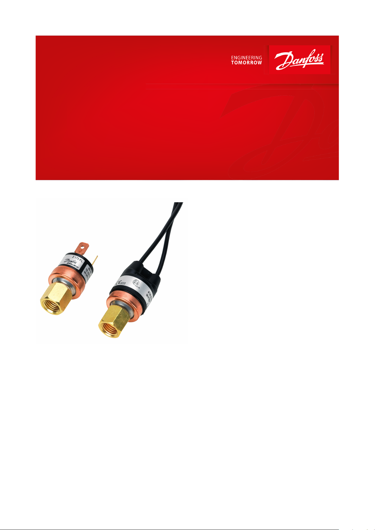
Cartridge pressure switch
Type ACB and CCB
Fixed setpoints
Pressure controls ACB and CCB are compact
disc type pressure switches with xed setpoints for long-standing use in refrigeration
and air conditioning systems. They provide
automatic or manual reset limit protection.
The small size, lightness and high degree of
protection means that it can be mounted
directly on the refrigeration systems.
The cartridge switch is available with dierent
pressure settings and pressure connections to
suit customer requirements.
All these features reduce installation costs and
save space.
Features:
• Wide range
• Fixed pressure set points
• Automatic or manual reset
• Various port ttings for soldering or direct
mounting
• Spades or cables
• Stripped ends or customer specic electrical
plug
• Open or water-proof (IP65) version
• Type ACB for use as high and low pressure cut
in and cut out as well as fan cycling
• Type CCB available for CO2 refrigerants
• Compact design and easy to install
AI224286438133en-000901
Page 2
1
5
2
4
3
6
7
1234567
High Pressure
Fan Control
Condenser
Compressor
Low Pressure
Evaporator
Expansion valve
Type
ACB
CCB
Water-proof (W)
Open – spade connector (O)
Water-proof (W)
Medium
R22, R134a, R404A, R407C, R407F, R410A, R438A, R448A, R449A, R452A, R513A.
For ammable refrigerants please contact your nearest Danfoss oce. For com-
plete list of approved refrigerants, visit www.products.danfoss.com and search for
individual code numbers, where refrigerants are listed as part of technical data
R744 (CO2)
Range
-0.5 – 45 bar / -7 – 652 psi
100 – 150 bar / 1450 – 2176 psi
Reset
Automatic, Manual
Automatic
Contact function
SPST-NO, SPST-NC, SPDT
SPST-NC
Electrical connections
AWG18 cables
Spades (size 6.35mm x 0.8 mm)
AWG18 cables
Cable length
150 cm (black)
-
150 cm (black)
Contact load variants
6 A @ 250 V AC for SPST
4 A @ 250 V AC for SPDT-0,01 - 0,05 A @ 12/24 V DC
Pressure connections
1⁄4 in ODM solder
6.35 mm solder
6 mm ODM solder
1⁄4 in SAE female
are
with depressure pin
Maximum working pressure PS / MWP
45 bar / 650 psi
165 bar / 2393 psi
Burst pressure
140 bar / 2030 psi
375 bar / 5440 psi
Media temperature
– 55 – 135 °C / –67 – 275 °F
– 30 – 100 °C / –20 – 210 °F
Ambient temperature
–30 – 85 °C / -20 – 185 °F
Enclosure
IP65
No electrical protection
IP65
Cartridge pressure switch, type ACB and CCB
Applications
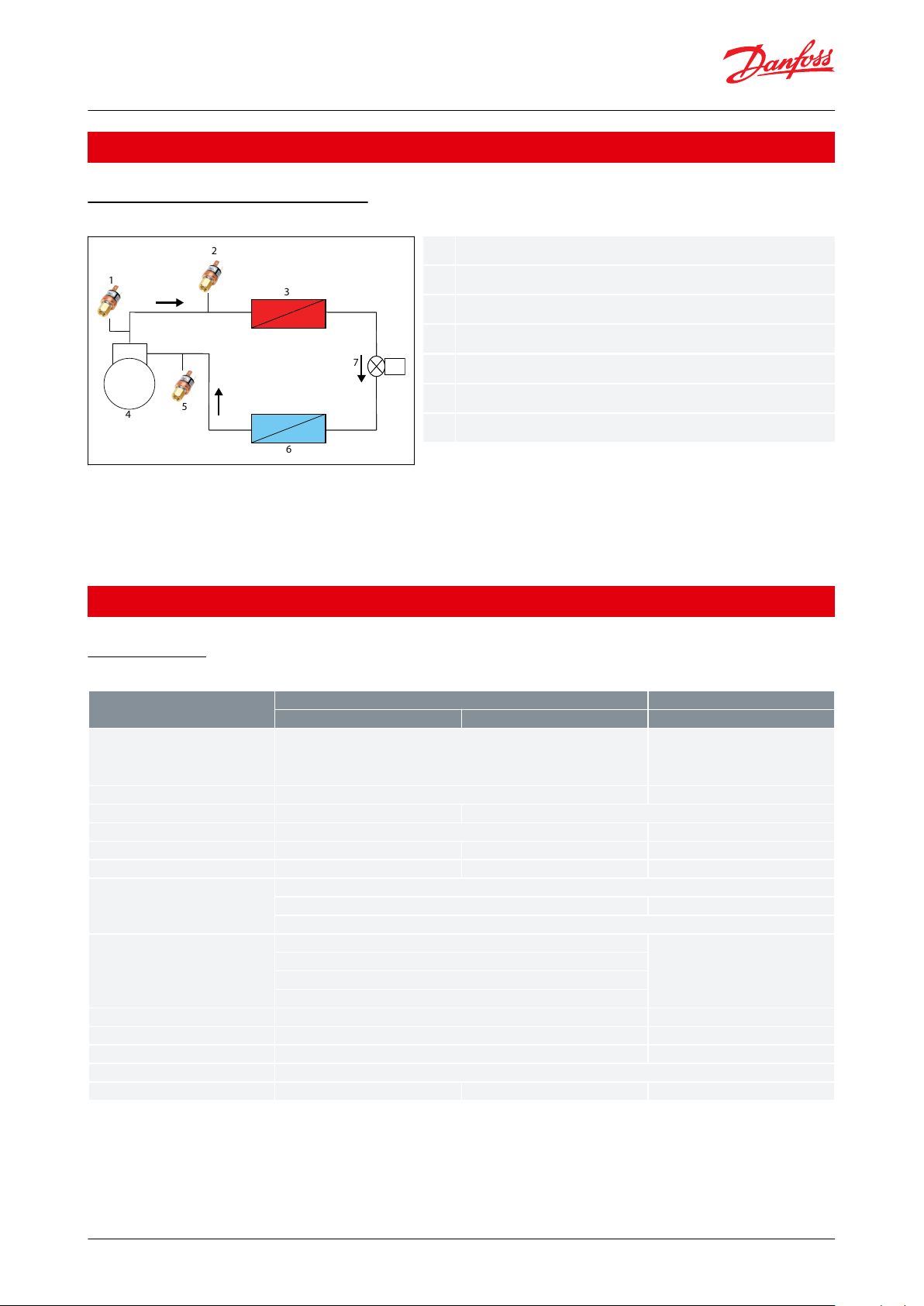
Air conditioning and refrigeration
Figure 1: Air conditioning and refrigeration
• Condenser fan switch
• Compressor stop – start
• Pump-down switch
• Low Pressure safety pressure switch
• High Pressure safety pressure switch
Product specication
Technical data
Table 1: Technical data
Customer specic features are available in a wide selection.
© Danfoss | Climate Solutions | 2021.03 AI224286438133en-000901 | 2
Page 3
0 500000 1000000 1500000
C
L
Danfos
60N9020
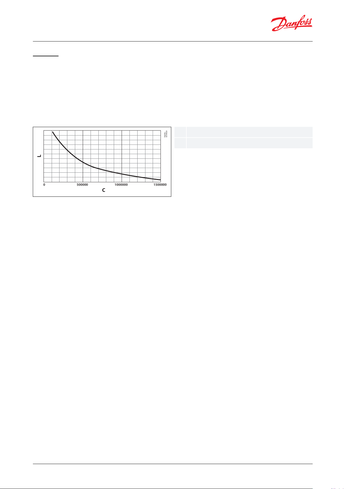
CLNumber of cycles
Electrical load
Cartridge pressure switch, type ACB and CCB
Lifetime
Switch type:
SPST auto reset, Normally open
Pressure setting : max 3 MPa
As general rule, ACB pressure switches are capable to cover applications requiring cycling from 100000 to 1500000
cycles dependent on current load. The exact number of cycles in any of given application is to be determined by
appropriate testing.
Manufacturer reserves the right to change or modify specications at any time without prior notice.
SPST auto reset, Normally close – up to 100000 cycles
SPST manual reset, Normally close – 10000 cycles
SPDT auto reset – up to 100000 cycles
SPDT manual reset – 10000 cycles
© Danfoss | Climate Solutions | 2021.03 AI224286438133en-000901 | 3
Page 4
Fiel d Code
Exp lanat ion
Pro duct
Ele ctrica l ratin g
1U
1A @ 250V AC
2U 6A @ 25 0V AC (SPST ), 4A @ 25 0V AC (SPDT )
4U 0,05A @ 12/24V DC ( gold con tacts)
Cont act
A
SPST- NO
B
SPST- NC
C
SPDT
Appr ovals
0 CE [cat egory I I] appr oval
1 CE [cat egory I I + IV], TÜV, VD E, UL & C-U L appr ovals (on ly with A CB)
2 UL & C- UL appr ovals (on ly with ACB)
3 CE [cat egory I I + IV] a pprova l (only wi th ACB)
Encl osure
O
Open
W
Wate rproo f IP65 (on ly with c ables)
Rese t
A
Auto matic
M
Manu al (not S PST-NO; SPDT onl y in Pan el mount housin g)
Hous ing
R Regu lar hot -melt
E
Epox y typ e
P
Pane l mount (m andat ory for SPDT Ma nual re set ver sions)
Por t fittin g
M
1/4” SAE f emale fl are w. de flator
V
1/4” SAE f emale fl are w. 1mm d eflato r
H
1/4” SAE m ale fla re
P
1/4” sol der Cu- tube (ti p = 3 mm)
X
1/4” sol der Cu- tube (ti p = 7 mm)
S
1/4” sol der Cu- tube (no t ip)
L
6 mm so lder Cu- tube (ti p = 7mm)
E
1/8-27 NP T male
Y
R (PT ) 1/8”
Uppe r activ ation s ettin g [bar gu age]
--,-
Toler ance on up per set ting [b ar]
-,-
+/- indi cated v alue
Lowe r activa tion s ettin g [bar gua ge]
--,-
Toler ance on lo w setti ng [bar]
-,-
+/- indi cated v alue
Ele ctrica l connec tion
A
AWG18 cab les
B
AWG16 cab les
C
AWG18 (UL 3173) cables
S
90 de g. spad es
D
Doub le insul ated AW G18 cables
V
Doub le insu lated H 05VV5 -F 2-in -1 cable (o n reque st only, E housin g only, Au tomat ic reset only)
R
Doub le insu lated H 05RNF 2 -in-1 cab le (on req uest on ly, E hous ing onl y, Autom atic re set only )
P
AWG18 wit h PVC tub e
H
AWG18 hal ogen fr ee (RoH S compli ant, cu rrent ly E hous ing onl y)
Cabl e lengh t in cm
---
Plea se use on e of stan dard le ngths : 020, 05 0, 080, 100, 150, 2 00 & 250 c m
Cabl e plug
(Leav e blank if no cab le)
0 Cut en ds
Fast on
A
A1: AMP 170213 -2, A2: A MP 170213-2, A 3: OBR# 250, A4 : AMP 73522 2-2+AMP 7 35222-2, A 5: AMP 170183 -2, A6: A MP 170213-2
AMP
B
B1: AMP 350777-1, B2 : AMP 282 080-1, B3 : AMP 28210 4-1, B4: AMP 192167-2, B 5: AMP 8 81772-1, B6: A MP 174354-2
Mol ex M
M1: 5557- 02R
Pin co nnecto r P
P1: Pho enix 32 00250, P 2: AMP 35 0218-1, P3: AM P 170213-2+AMP 926933-1, P4 : AMP 926 882-1, P5: A MP 165590 -1
Pack ard Q
Q1: 1201097 3, Q2: 120157 92, Q3: 153 00002 , Q4: 1530 0027, Q5: 1202 0829
Stri pped en d S
S1: str ipped e nds 15mm, S2: str ipped e nds 10mm
VHR
V
V1: VH R-2N, V2 : VHR -3N
WAGO
W
W1: 231-30 2/026- 000, W2 : 769-102/0 21-000
Addi tiona l featu res
Leav e blank i f no add itiona l speci ficatio ns
X
Plea se spec ify (cl ear tex t atta chment)
Deta ils of s pecial featur es (if an y)
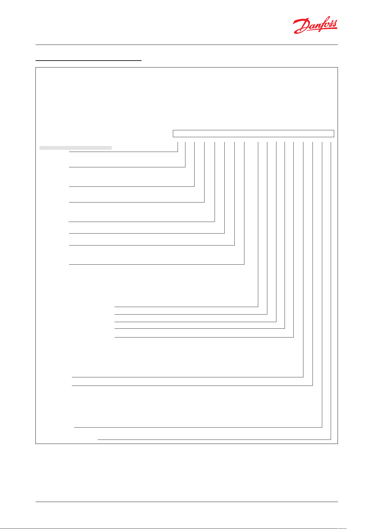
ACBExample:
Requ ested s pecs:
Pro duct
Ele ctrica l ratin g
Cont act
Appr ovals
Encl osure
Rese t
Hous ing
Por t fittin g
Uppe r activ ation s ettin g [bar gu age]
Toler ance on up per set ting [b ar]
Lowe r activa tion s ettin g [bar gua ge]
Toler ance on lo w setti ng [bar]
Ele ctrica l connec tion
Cabl e lengh t in cm
Cabl e plug
Mar k if addi tiona l speci ficatio ns
Deta ils of s pecial featur es (if an y)
2U B 1 W A R L 20,0 1,0 15,0 1,5 100 0A
Cartridge pressure switch, type ACB and CCB
Specication build up Type ACB
© Danfoss | Climate Solutions | 2021.03 AI224286438133en-000901 | 4
Page 5

1
2
3
4
5
6
7
8
9
123456789
Wires
Reset button
Water-proof casing
Diaphragm
Pressure connection (
1
⁄4 in female are)
Electrical terminals
Micro-switch
Shaft
Depressure pin
SPDT
SPDT with manual reset
SPST NO
SPST NC
SPST with manual reset
p
C
H L
p
C
H L
p
C
L
p
C
p
C
HH
Danfoss
61F010.10
Cartridge pressure switch, type ACB and CCB
Electrical connections
Table 2: Electrical connections
SPST - Single Pole Single Throw
SPDT - Single Pole Double Throw
(NO) - Normally Open
(NC) - Normally Closed
Design
Figure 2: ACB - SPST manual reset
As pressure is applied through the connection on to the diaphragm, the diaphragm is pushed up against the
operation shaft.
When the operation shaft rises, it pushes up the contact plate, so that contacts become connected (in normally
open) or disconnected (in normally closed).
As the pressure in the connection decreases, the diaphragm returns to its original state, and the operation shaft
lowers, causing the contact plate to return to its original position.
© Danfoss | Climate Solutions | 2021.03 AI224286438133en-000901 | 5
Page 6

With automatic reset 1⁄4 in solder type
With automatic reset female are
24
33
φ23.5
HEAT PROOF ELECTRIC VINYL WIRE
UL1015, AWG18, 105 °C (BLACK)
58.2
3
φ6.35 ±0.1
(φ8)
1500 ±50
LABEL
Danfoss
61F014
Danfoss
61F015
HEAT PROOF ELECTRIC VINYL WIRE
33
24
φ23.5
16.4 ±1.5
7/16-20 UNF FOR FLARE
HEX 14
With Depressor pin
UL3173, AWG18, 125 °C (BLACK)
2500 ±80
LABEL
Net weight: 0.072 kg
Net weight: 0.080 kg
With manual reset 6 mm solder type
With automatic reset 6 mm solder type
Danfoss
61F004
LABEL
φ24±0.5
(φ8)
RESET BUTTON
HEAT PROOF ELECTRIC VINYL WIRE
32±1
7
φ6±0.1
(φ7)
φ6.35±0.1
59
UL1015, AWG18, 105 °C (BLACK)
1000±50
Danfoss
61F016
24
33
φ23.5
58.2
7
(φ7)
φ6 ±0.1
φ6.35 ±0.1
HEAT PROOF ELECTRIC VINYL WIRE
UL1015, AWG18, 105 °C (BLACK)
780 ±30
LABEL
Net weight: 0.078 kg
Net weight: 0.072 kg
Cartridge pressure switch, type ACB and CCB
Dimensions [mm] and weights [kg]
Table 3: Type ACB – SPST water-proof
Table 4: Type ACB – SPST water-proof
© Danfoss | Climate Solutions | 2021.03 AI224286438133en-000901 | 6
Page 7

With automatic reset
With manual reset
RED
BLUE
BLACK
φ25.4
50.4
16.4
LABEL
7/16-20 UNF FOR FLARE
HEX 14
With Depressor pin
UL3266, AWG18, 125 °C,300 V ( =1000±50)
AWM HALOGEN FREE CABLE
Danfoss
61F006
53.4
16.4
15
4
39
13
HEX 14
7/16-20 UNF FOR FLARE
10
M4×0.7
30
HEAT PROOF ELECTRIC VINYL WIRE
RED
BLACK
BLUE
With Depressor pin
LABEL
UL1015, AWG18, 105 °C( =1500±50)
Danfoss
61F007
Net weight: 0.114 kg
Net weight: 0.112 kg
Solder type
With female are
C
φ0.25"{φ6.35}
0.12"{3}
(φ0.31"{φ8})
φ0.85"{φ21.7}
0.41"{10.5}
FASTON TERMINAL
3-#250
LABEL
3.51"{89.1}
2.32"{59}
0.76"{19.2}
Danfoss
61F008
Danfoss
61F010
Net weight: 0.024 kg
Net weight: 0.029 kg
Cartridge pressure switch, type ACB and CCB
Table 5: Type ACB – SPDT
Table 6: Type ACB – SPDT open type
© Danfoss | Climate Solutions | 2021.03 AI224286438133en-000901 | 7
Page 8

With automatic reset 6.35 mm solder type
(24.5)
φ6.35±0.1
UL1015, AWG18, 105°C (BLACK)
HEAT PROOF ELECTRIC VINYL WIRE
8
+1
0
44±257.7±2
LABEL
1500±50
Danfoss
61F001
Net weight 0.125 kg
Reset
Cut out
Cut in
Contact system / enclosure
type W-water-proof types
with cable (IP65) O-open
(spade connector) types / no
cable (IP00)
Connection type
[bar] [psi]
[bar] [psi]
Solder
Flare
6 mm
1
⁄4
in
7
⁄16
-20 UNF with de‐
pressure pin
Auto.
18 ± 0.7 / 260 ± 10
13 ± 1.2 / 190 ± 17
SPST-NC / W
061F7504
ACB-2UB504W
061F7505
ACB-2UB505W
061F7506
ACB-2UB506W
SPDT / W
–
–
061F9057
ACB-2UC59W
20 ± 1 / 290 ± 14
16 ± 1.5 / 230 ± 21
SPST-NC / O
–
061F8710
ACB-2UB210
061F8708
ACB-2UB208
Auto.
23 ± 0.7 / 335 ± 10
19 ± 1.2 / 275 ± 17
SPST-NC / W
–
–
061F8494
ACB-2UB465W
SPST-NC / O
–
061F8707
ACB-2UB207
061F8703
ACB-2UB203
SPDT / W
–
–
061F9056
ACB-2UC58W
Man.––
061F9243
ACB-2UC63MW
Auto.
26 ± 1 / 380 ± 15
20 ± 1.5 / 290 ± 22
SPST-NC / W
061F7507
ACB-2UB507W
061F7508
ACB-2UB508W
061F7509
ACB-2UB509W
SPST-NC / O
–
061F8705
ACB-2UB205
061F8701
ACB-2UB201
Man.
SPST-NC / W
061F9703
ACB-2UB803MW
061F9714
ACB-2UB814MW
061F9713
ACB-2UB813MW
Auto.
SPDT / W
–
–
061F9055
ACB-2UC57W
Auto.
28 ± 1 / 405 ± 14
21 ± 1.5 / 305 ± 22
SPST-NC / W
061F7510
ACB-2UB510W
061F7513
ACB-2UB513W
061F7514
ACB-2UB514W
Man.––
061F9522
ACB-2UB327MW
Auto.
SPST-NC / O
–
061F8704
ACB-2UB204
061F8700
ACB-2UB200
Auto.
SPDT / W
–
–
061F9054
ACB-2UC56W
Man.
SPDT / W
–
–
061F9242
ACB-2UC62MW
Cartridge pressure switch, type ACB and CCB
Table 7: Type CCB - SPST water proof
Ordering
Standard models
Type ACB
Table 8: High pressure cut out
© Danfoss | Climate Solutions | 2021.03 AI224286438133en-000901 | 8
Page 9

Reset
Cut out
Cut in
Contact system / enclosure
type W-water-proof types
with cable (IP65) O-open
(spade connector) types / no
cable (IP00)
Connection type
[bar] [psi]
[bar] [psi]
Solder
Flare
6 mm
1
⁄4 in
7
⁄16-20 UNF with de‐
pressure pin
Auto.
31 ± 1 / 405 ± 14
24 ± 1.5 / 350 ± 22
SPST-NC / W
061F8493
ACB-2UB464W
–
061F8492
ACB-2UB463W
SPST-NC / O
–
061F8706
ACB-2UB206
061F8702
ACB-2UB202
SPDT / W
–
–
061F9053
ACB-2UC55W
Auto.
42 ± 1.2 / 610 ± 17
33 ± 2 / 480 ± 29
SPST-NC / W
061F7515
ACB-2UB515W
061F7516
ACB-2UB516W
061F7517
ACB-2UB517W
Man.––
061F9575
ACB-2UB461MW
Auto.
SPDT / W
–
–
061F9052
ACB-2UC54W
Reset
Cut out
Cut in
Contact system / enclosure
type W-water-proof types
with cable (IP65) O-open
(spade connector) types / no
cable (IP00)
Connection type
[bar] [psi]
[bar] [psi]
Solder
Flare
6 mm
1
⁄4 in
7
⁄16
-20 UNF with de‐
pressure pin
Auto.
0.5 ± 0.4 / 7 ± 6
1.5 ± 0.5 / 22 ± 4
SPST-NO / W
061F7518
ACB-2UA518W
061F7519
ACB-2UA519W
061F7520
ACB-2UA520W
SPST-NO / O
–
061F7402
ACB-2UA152
061F7400
ACB-2UA150
SPDT / O
–
061F9106
ACB-2UC106
061F9102
ACB-2UC102
Auto.
0.7 ± 0.5 / 10 ± 7
1.7 ± 0.4 / 25 ± 6
SPST-NO / W
061F7521
ACB-2UA521W
061F7522
ACB-2UA522W
061F7523
ACB-2UA523W
SPDT / W
–
–
061F9058
ACB-2UC60W
Auto.
1.7 ± 0.5 / 25 ± 7
2.7 ± 0.4 / 39 ± 6
SPST-NO / W
061F7524
ACB-2UA524W
061F7525
ACB-2UA525W
061F7526
ACB-2UA526W
Auto.
2.2 ± 0.3 / 32 ± 4.5
3.4 ± 0.3 / 50 ± 4.5
SPST-NO / W
061F7418
ACB-2UA711W
–
–
Reset
Cut out
Cut in
Contact system / enclosure type
W-water-proof types with cable
(IP65) O-open (spade connector)
types / no cable (IP00)
Connection type
[bar] [psi]
[bar] [psi]
Solder
Flare
6 mm
1⁄4 in
7/16-20 UNF with de‐
pressure pin
Auto.
8.5 ± 1.2 / 125 ± 17
11 ± 0.8 / 160 ± 12
SPST-NO / W
061F8491
ACB-2UA393W
–
061F8490 ACB-2UA392W
13 ± 1.5 / 190 ± 22
16 ± 1 / 230 ± 14
061F8334
ACB-2UA306W
–
061F8333 ACB-2UA305W
Danfoss
61F8025.10
Cartridge pressure switch, type ACB and CCB
NOTE:
Other code numbers are available upon request.
Table 9: Low pressure control
Table 10: Fan control
Type CCB
Figure 3: Type CCB
© Danfoss | Climate Solutions | 2021.03 AI224286438133en-000901 | 9
Page 10

Reset
Cut out
Cut in
Contact system / enclosure type Wwater-proof types with cable (IP65)
Connection type
[bar] [psi]
[bar] [psi]
Solder 6.35 mm
Packing 100 pcs.
Packing 20 pcs.
Auto.
100±10 / 1450±145
70±20 / 1015±290
SPST-NC / W
061F9808
CCB-2UB03W
061F9908
CCB-2UB03W
110±10 / 1595±145
80±20 / 1160±290
061F9809
CCB-2UB04W
061F9909
CCB-2UB04W
120±10 / 1740±145
90±20 / 1305±290
061F9810
CCB-2UB05W
061F9910
CCB-2UB05W
130±10 / 1885±145
100±20 / 1450±290
061F9811
CCB-2UB06W
–
140±10 / 2030±145
100±20 / 1450±290
061F9812
CCB-2UB07W
–
150±10 / 2175±145
100±20 / 1450±290
061F9813
CCB-2UB08W
–
Standard cable length [m]
(1)
Packing quantity
Code no.
2.5
100
061F13026100
061F1304
Cartridge pressure switch, type ACB and CCB
Table 11: High pressure control
Accessories
Figure 4: Rubber plug
A wide variety of cartridge switches are available with open enclosure - no electric protection. For these switches a
water-proof rubber plug has been specially designed.
When the plug is installed on the switch a water-proof seal IP64 is obtained. The water-proof rubber plug is available
with many dierent cable lengths.
Table 12: Accessories
(1)
(1)
Other cable lengths available upon request.
Other cable lengths available upon request.
© Danfoss | Climate Solutions | 2021.03 AI224286438133en-000901 | 10
Page 11

File name
Document type
Document topic
Approval_authority
UA.1O146.D.00075-19
UA Declaration
EMCD/LVD
LLC CDC EURO TYSK
Saginomiya 02-16
Manufacturers Declaration
China RoHS
Danfoss
RU Д-DK.ГА02.В.03367
EAC Declaration
EMC
EAC
RU C-DK.БЛ08.В.00063_18
Electrical - Safety Certicate
EMC/LVE
EAC
01 202 931 Q-04 0018
Quality - Assurance Certicate
PED
TÜV
01 202 973-B-17-0002
Pressure - Safety Certicate
-
TÜV
Cartridge pressure switch, type ACB and CCB
Certicates, declarations, and approvals
The list contains all certicates, declarations, and approvals for this product type. Individual code number may have
some or all of these approvals, and certain local approvals may not appear on the list.
Some approvals may change over time. You can check the most current status at danfoss.com or contact your local
Danfoss representative if you have any questions.
Table 13: Certicates, declarations, and approvals
• CE according to EN 12263
• Technical Inspection Association TÜV TUV certicate no. 01 202 931/Q-04 0018 and 01 202 971/B-17-0002
• Low Voltage Directive 2014/35/EU
• UL recognized (type ACB only):
◦ UL 873 and CSA C22.2 No. 24-93
◦ UL 121201 and CSA C22/2 No.213-17 (for ammable refrigerants only)
© Danfoss | Climate Solutions | 2021.03 AI224286438133en-000901 | 11
Page 12

Online support
Danfoss oers a wide range of support along with our products, including digital product information, software,
mobile apps, and expert guidance. See the possibilities below.
The Danfoss Product Store
The Danfoss Product Store is your one-stop shop for everything product related—no matter where
you are in the world or what area of the cooling industry you work in. Get quick access to essential
information like product specs, code numbers, technical documentation, certications, accessories,
and more.
Start browsing at store.danfoss.com.
Find technical documentation
Find the technical documentation you need to get your project up and running. Get direct access to
our ocial collection of data sheets, certicates and declarations, manuals and guides, 3D models
and drawings, case stories, brochures, and much more.
Start searching now at www.danfoss.com/en/service-and-support/documentation.
Danfoss Learning
Danfoss Learning is a free online learning platform. It features courses and materials specically
designed to help engineers, installers, service technicians, and wholesalers better understand the
products, applications, industry topics, and trends that will help you do your job better.
Create your Danfoss Learning account for free at www.danfoss.com/en/service-and-support/learning.
Get local information and support
Local Danfoss websites are the main sources for help and information about our company and
products. Find product availability, get the latest regional news, or connect with a nearby expert—all
in your own language.
Find your local Danfoss website here: www.danfoss.com/en/choose-region.
Coolselector®2 - nd the best components for you HVAC/R system
Coolselector®2 makes it easy for engineers, consultants, and designers to nd and order the best
components for refrigeration and air conditioning systems. Run calculations based on your operating
conditions and then choose the best setup for your system design.
Download Coolselector®2 for free at coolselector.danfoss.com.
Danfoss can accept no responsibility for possible errors in catalogues, brochures and other printed material. Danfoss reserves the right to alter its
products without notice. This also applies to products already on order provided that such alterations can be made without subsequential
changes being necessary in specications already agreed. All trademarks in this material are property of the respective companies. Danfoss and
the Danfoss logotype are trademarks of Danfoss A/S. All rights reserved.
© Danfoss | Climate Solutions | 2021.03 AI224286438133en-000901 | 12
 Loading...