

Page 1
Data sheet
ABN A5 Actuator for AB-QM, ON/OFF
Application
The ABN A5 on/off thermal actuator has been
specifically designed for use with AB-QM valves
DN10-32/½-1¼ inch in heating and cooling
applications.
Function The actuator mechanism of the ABN A5 actuator
uses a positive temperature coefficient (PTC)
resistor heated wax element and a compression
spring. The wax element is heated by applying
the operating voltage and moves the integrated
piston. The force generated by this movement is
transferred to the piston, thus opening or closing
the valve.
First open function (for NC versions only)
In its delivery condition, the ABN A5 is kept
open when de-energized due to the first open
function (filling). This enables heating/cooling
operation during the carcass construction
phase even when the electric wiring is not yet
complete. During the later electrical start-up, the
first open function is unlocked by applying the
operating voltage for more than 6 minutes and
the ABN A5 will then be completely operable.
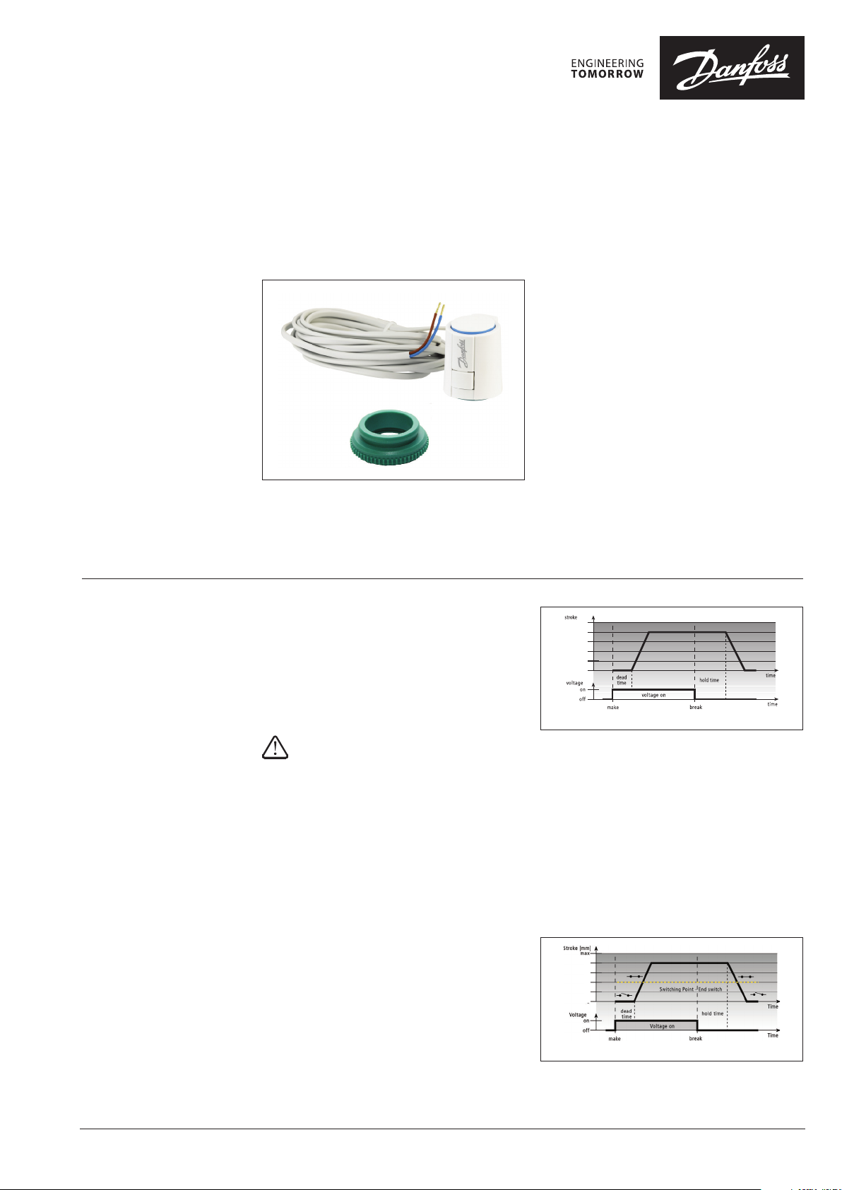
Version NC “normally closed” (valve closed)
In case of the normally closed version, the valve
is opened steadily by the ram motion upon
switching on the operating voltage and after
expiry of the dead time.
After the operating voltage is cut and after
expiry of the hold time, the valve is closed evenly
by the closing force of the compression spring.
The closing force of the actuator is matched
to AB-QM DN10-32 valves and keeps the valve
closed when de-energised.
Actuator convincing features are:
• Stroke 5.0 mm
• Available as normally closed (NC) or normally
open (NO)
• Power consumption 1W
• Plug-in cable
• Simple snap-on installation
• IP54 in any installation position
• First-Open function
• Compact size, small dimensions
• All round function indicator
• Noiseless and maintenance-free
• Certified by TÜV
The actuator can be controlled with an on/off
or PWM controller which is provided either by
a room thermostat or by a central direct digital
control (DDC) system.
Fig. 1: Example of opening cur ve.
Version NC with end switch (082F1154)
The integrated micro switch is switched at a
travel path of approx. 2 mm.
After the operating voltage is cut and after
expiry of the hold time the valve is closed evenly
by the closing force of the compression spring.
The integrated switch is closed after an actuator
travel of approx. 2 mm.
The closing force of the compression spring is
matched to the closing force of commercially
available valves and keeps the valve closed when
de-energised.
Fig. 2: Example of opening curve.
© Danfoss | 2019.04
VD.SK.I3.02 | 1
Page 2
Data sheet ABN A5 Actuator for AB-QM, ON/OFF
Function (continuous)
Ordering
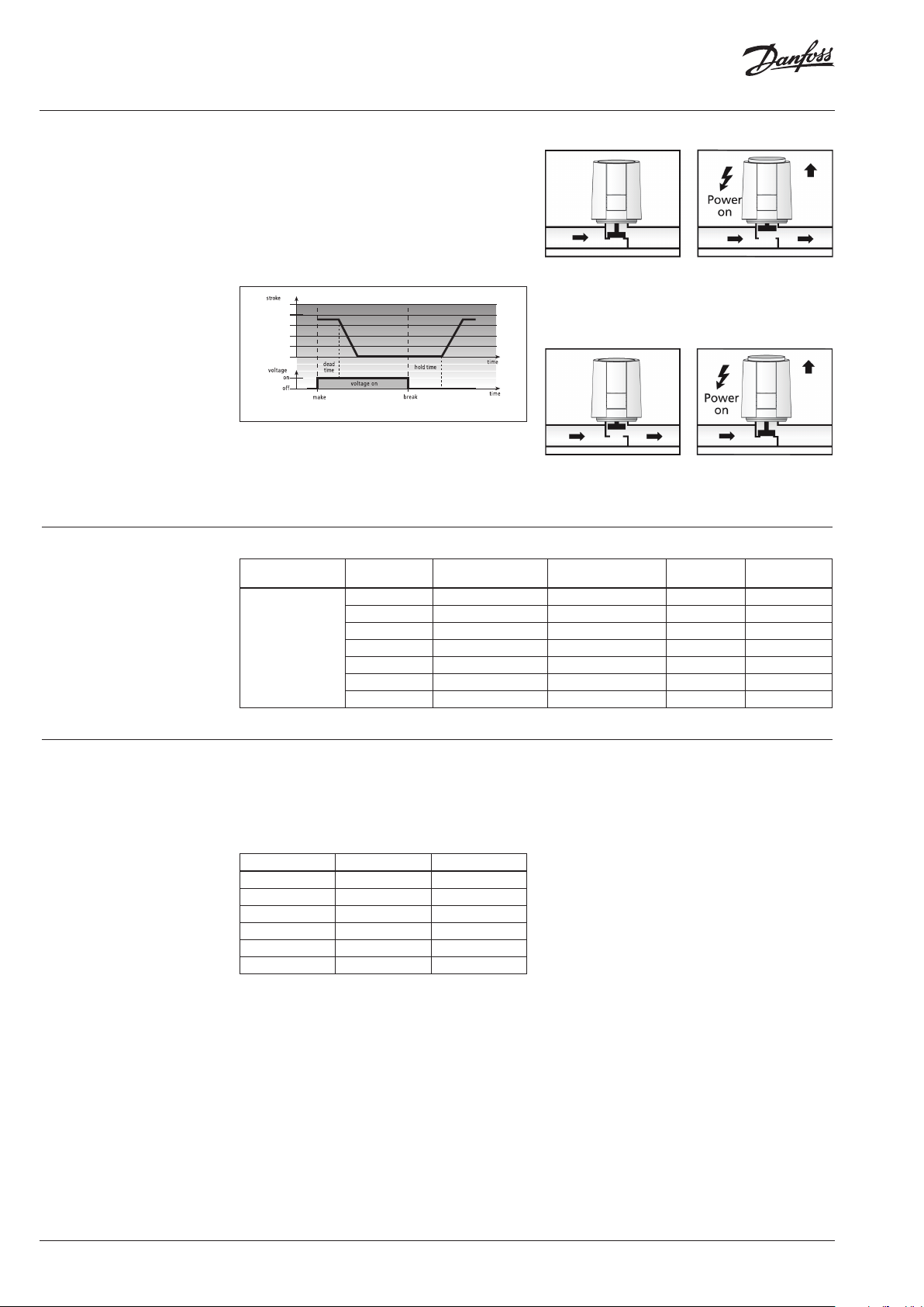
Version NO “normally open”
In case of the normally open version, the valve
is closed steadily by the ram motion upon
switching on the operating voltage and after
expiry of the dead time.
After the operating voltage is cut and after
expiry of the hold time, the valve is opened
evenly by the compressive force of the valve
spring.
Fig. 3: Example of closing curve.
Function display
The function display of the ABN A5 (all-round
display) allows identifying the operating
condition (valve open or closed) at a glance.
Typ e Supply voltage
24 VAC /DC NC Plug-in, not included No 08 2F115 0
24 VAC /DC NO Plug-in, not included No 0 82F 1151
ABN A5,
with VA 41 adapter,
without cable
230 VAC NC Plug-in, not included No 082 F115 2
230 VAC NO Plug-in, not included No 082 F115 3
24 VAC /DC NC Fixed, 1 m Yes 082F1154
120 VAC NC Plug-in, not included No 08 2F115 6
120 VAC NO Plug-in, not included No 082 F1157
Normally Open/
Normally Closed
Fig. 4: Function display for NC versions extends
proportionally with actuator opening from 0 mm
to 5-6 mm.
Fig. 5: Function display for NO versions extends
only when valve is fully closed by approx. 0.5 mm.
Cable End Switch Code No.
Cables
Cables are not included and should be ordered
separately (not valid version with end switch).
It is possible to select between different lengths
and standard or halogen free material.
Cables Material Code No.
1 meter Standard (PVC) 08 2F114 4
5 metres Standard (PVC) 0 82F 1145
10 me tres Standard (PVC) 0 82F114 6
1 meter Halogen free 082F1147
5 metres Halogen free 08 2F11 48
10 me tres Halogen free 082F 1149
2 | © Danfoss | 2019.04
VD.SK.I3.02
Page 3

Data sheet ABN A5 Actuator for AB-QM, ON/OFF
Data
ABN A5 type 24 V 230 V
Version NC/NO NC/NO
Voltage 24 V AC/DC, +20 %...-10 %, 0-60 Hz 230 V AC, +10 %...-10 %, 50/60 Hz
Max. inrush current < 300 mA during max. 2 min. < 550 mA during max. 200 ms
Operating power 1 W
Control voltage On/Of f On/Of f
Actuator travel 5 mm 5 mm
Actuating force 100 N 100 N
Closing and opening time ~4 min. ~4 min.
Fluid temperature 0 - 100 °C 0 - 100 °C
Storage temperature -25 to 65 °C -25 to 65 °C
Ambient temperature 0 to 60 °C 0 to 60 °C
Ambient humidity 95% r.h., non-condensing
Degree/class of protection IP542)/III safety extra-Iow voltage IP542)/II
CE conformity according to EN60730, UL60730 EN60730, UL60730
Housing/housing colour Polyamid/White R AL9003 Polyamid/White R AL9003
Connecting cable 2 x 0.75 mm² PVC, or halogen free 2 x 0.75 mm² PVC, or halogen free
Adapter (included) VA 41 VA 41
Overvoltage resistance EN60730-1 min. 2.5 kV min. 2.5 kV
Weight 0.1 kg 0.1 kg
1)
Measured with p recision reference instrum ent LMG95.
2)
In all installati on positions.
End switch versio n. Switching current for micro swi tch :24V, 3A resistive load, 1A inductive lo ad.
1)
1 W
1)
Connections
yellow
Operating Voltage 24V AC-DC
red
End-Switch
Cable connection of version with end switch 082F1154.
VD.SK.I3.02
© Danfoss | 2019.04 | 3
Page 4

Data sheet ABN A5 Actuator for AB-QM, ON/OFF
①
Installation
Installation with valve adapter
Danfoss AB-QM VA41
Screw the valve adapter manually onto the valve. Connect cable and actuator.
②
Click
max: 4mm
IP54 in any position
with cable plugged in
First Open Function
Place the actuator vertically on the valve adapter. The
actuator snaps onto the valve adapter with a “click”
when pressed down ver tically by hand.
The actuator is dismounted by pressing the knob and
pull of the actuator vertically.
4 | © Danfoss | 2019.04
Presentation of First Open Function (Unlock NC version).
VD.SK.I3.02
Page 5

Data sheet ABN A5 Actuator for AB-QM, ON/OFF
50,3 mm 7 mm
56 mm 44,3
Dimensions
52,2 mm
VD.SK.I3.02
© Danfoss | 2019.04 | 5
Page 6

Data sheet ABN A5 Actuator for AB-QM, ON/OFF
6 | © Danfoss | 2019.04
VD.SK.I3.02
Page 7

Data sheet ABN A5 Actuator for AB-QM, ON/OFF
VD.SK.I3.02
© Danfoss | 2019.04 | 7
Page 8

Danf
already on order pro
All trademarks in this material are property of the respec
Data sheet ABN A5 Actuator for AB-QM, ON/OFF
oss can accept no responsibility for possible errors in catalogues, brochures and other printed material. Danfoss reserves the right to alter its products without notice. This also applies to products
vided that such alterations can be made without subsequential changes being necessary eady agreed.
8 | © Danfoss | DHS-SRMT/SI | 2019.04
tive companies. Danfoss and the Danfoss logotype are trademarks of Danfoss A/S. All rights reserved.
VD.SK.I3.02
 Loading...