

Page 1
841 & 842
Seven Day Pulsed Output Electronic Timeswitches
110 Volt
INSTALLATION INSTRUCTIONS
The Model 841 & 842 Timeswitches must be installed
by a competent electrician and the installation should
conform to IEE Wiring Regulations.
Installation & Wiring
1. Slacken the four fi xing screws, one in each corner of the unit, and
carefully separate the front and rear portions. Unplug the ribbon cable
from the rear portion.
CAUTION: Do not allow either half of the unit to hang by the ribbon
cable as damage could be caused.
2. Remove the polystyrene packing piece from the top of the transformer.
It is marked ‘REMOVE’.
3. Select the desired fi xing position and observe the label ‘THIS WAY UP’
inside the rear portion. The two halves will only assemble correctly
one way round.
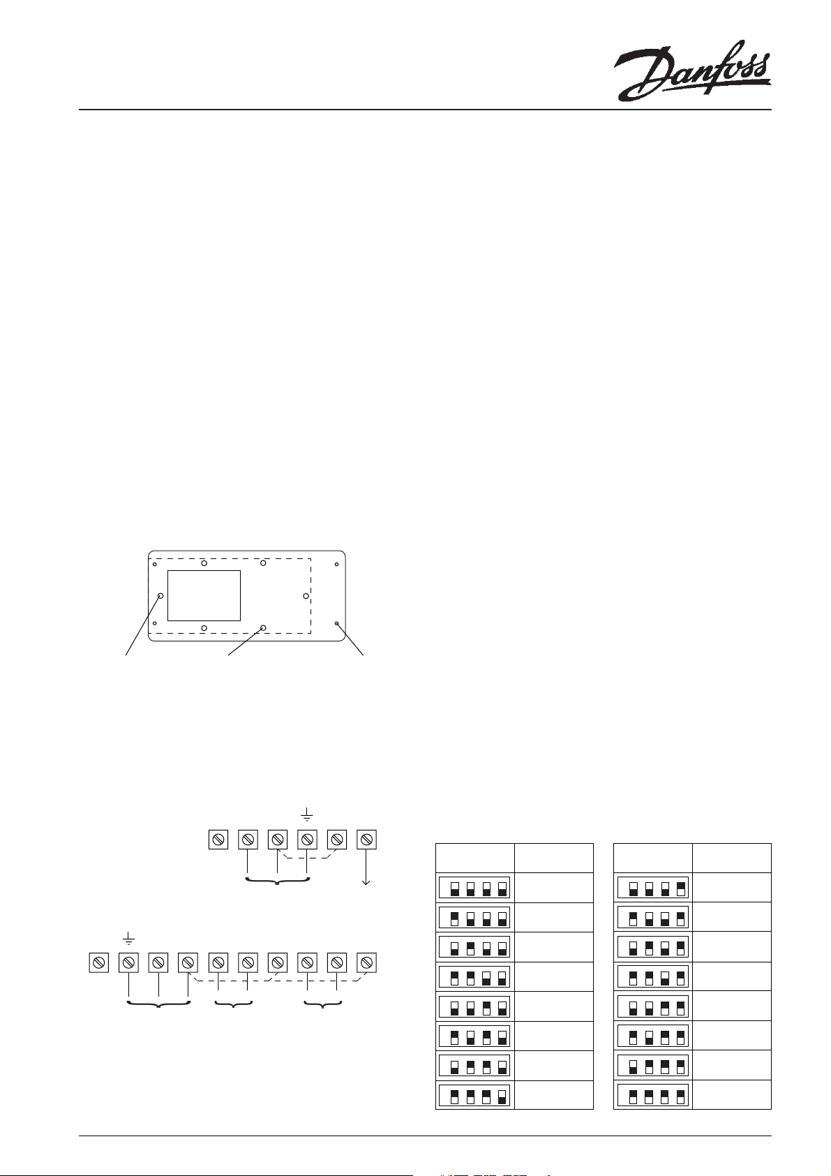
4. Four fi xing holes are provided for attaching the rear portion to the
wall or mounting surface.
Conduit box adaptors as shown below are available if required.
Part No.: 8/3223 Double Gang Surface Box Adaptor
Cable
Entry
Aperture
2 fi xings for
double gang
surface box
5. Surface cable entries to the units can be made from above, below or
from the left hand side. Conduit or recessed cable entry is through the
aperture in the rear moulding.
6. For surface cable entr y remove the appropriate knock-out and ensure
one of the two cable clamps is positioned correctly.
7. Connections to the units should be made as shown below.
MODEL 841
Spare N L 1 2
Alternative 4 fi xings
for double gang
surface box
4 fi xings for Mark
8 Timeswitch
In the case of Model 842 terminals 1, 2 and 3 (if required) should be
connected to the load controlled by Channel 1 and terminals 4, 5 and
6 (if required) to the load controlled by Channel 2.
8. The unit is supplied set for a 5 second single pulse output. If a multi
pulse output is required, proceed as described in paragraph 10 (b). If a
number of pulses or the pulse duration is required to be different from
supplied, proceed as described in paragraph 11(b).
9. Upon completion of wiring plug in the ribbon cable ensuring the
polarised plug is fully inserted into the socket. Refi t the front half of the
timeswitch ensuring correct alignment and that no cables are trapped
before re-tightening the screws.
10. TO CHANGE FROM SINGLE TO MULTI PULSE OUTPUT
(a) Remove the front portion of the unit as described in ‘Installation
and Wiring’ paragraph 1.
(b) A push/pull switch is provided on the rear of the printed circuit
board inside the front portion of the unit.
With the switch pulled out (as supplied) this provides a single pulse
output. Push the switch in to achieve a multi pulse output (½ second
on followed by ½ second off).
On Model 842 a push/pull switch is provided for each channel to enable
different types of pulsed output if required. The switch relating to each
channel is clearly marked.
11. RESETTING OF SWITCHING DURATION
(a) Remove the front portion of the unit as described in ‘Installation
and Wiring’ paragraph 1.
(b) The bank of four miniature rocker switches is mounted on the
printed circuit board inside the front portion of the unit.
When switch no. 1 is ‘on’ 1 second duration is set.
When switch no. 2 is ‘on’ 2 seconds duration is set.
When switch no. 3 is ‘on’ 4 seconds duration is set.
When switch no. 4 is ‘on’ 8 seconds duration is set.
When all 4 switches are ‘on’ the duration is
1 + 2 + 4 + 8 = 15 seconds.
Any combination of the 4 switches may be selected to set from 1 to
15 seconds in increments of 1 second.
If all 4 switches were ‘off’ there would be no output and so this setting
should be avoided.
EXAMPLES
Link for 110V
control circuit
110V, 50 Hz
Mains Supply
Output
(LOAD)
MODEL 842
Spare N L 6 5 4 3 2 1
Link for
110V
control
circuit(s)
OFF ON
Channel 2
110V, 50 Hz
Mains Supply
OFF ON
Channel 2
If the control circuit(s) are to operate at 110V then terminals L & 1
(Model 841) and terminals L, 1 and 4 (Model 842) must be linked,
ensuring that the cable is sheathed and of a size to carry the required
load current.
If, however, the control circuit(s) are operating at other than 110V then
no link(s) shall be fi tted and in the case of Model 841 both terminals 1
and 2 should be connected to the load.
Slider Switch Posi-
tions
23
1
ON
OFF
23
1
ON
OFF
23
1
ON
OFF
23
1
ON
OFF
23
1
ON
OFF
23
1
ON
OFF
23
1
ON
OFF
23
1
ON
OFF
4
4
4
4
4
4
4
4
‘ON’
Duration
NONE
Do Not Use
1 second
2 seconds
3 seconds
4 seconds
5 seconds
(As supplied)
6 seconds
7 seconds
Slider Switch Posi-
tions
23
1
ON
OFF
23
1
ON
OFF
23
1
ON
OFF
23
1
ON
OFF
23
1
ON
OFF
23
1
ON
OFF
23
1
ON
OFF
23
1
ON
OFF
‘ON’
Duration
4
8 seconds
4
9 seconds
4
10 seconds
4
11 seconds
4
12 seconds
4
13 seconds
4
14 seconds
4
15 seconds
1
Page 2
Technical Specifi cation Model 841 Model 842
Max. current rating of output 15A at 110 Vac 3A* (at 110 Vac on each channel.
* If set as multi pulse output giving 15 pulses
per event 200 times per week, rating reduces
to 1A at 110 Vac
Conversely if set as single pulse at 100 events
per week, rating increases to 5A at 110 Vac
Output contacts Enclosed single pole single throw (SPST) Enclosed single pole double throw (SPDT)
Type B voltage free on each channel Type B
Mains supply required 110 V (+/-10%) AC 50/60 Hz 100V (+/-10%) AC 50/60 Hz
Battery reserve Retains memory settings for a period of 3 months during mains power failure (once battery is
fully charged)
Temperature Rating 0°C to 45°C
Enclosure Rating IP30
Max Ambient Temperature 45°C
Overall Dimensions 210mm wide, 115mm high, 50mm deep
Max. No. of programmable operations 200 which may be freely allocated throughout the 7 days
Setting and Running Accuracy +/- 1 min and +/- 1 min/month
Mode of operation Provides either a continuous or interrupted Provides either continuous or interrupted pulse
pulse (½ second ‘ON’ followed by ½ second (½ second ‘ON’ followed by ½ second ‘OFF’)
‘OFF’) for a duration of between 1-15 seconds on each channel for a duration of 1-15
at each programmed event. seconds at each programmed event.
The unit leaves the factory set for a single The unit leaves the factory with both channels
pulse of 5 seconds duration. This can be reset set for a single pulse of 5 seconds duration.
if required (see paragraphs 10 and 11 overleaf) Either or both of these can be reset
independently of each other to give differing
outputs (see paragraphs 10 and 11 overleaf).
Control Pollution Situation Degree 2
Software Classifi cation Class A
Rated Impulse Voltage 2.5kV
Ball Pressure Test 75°C
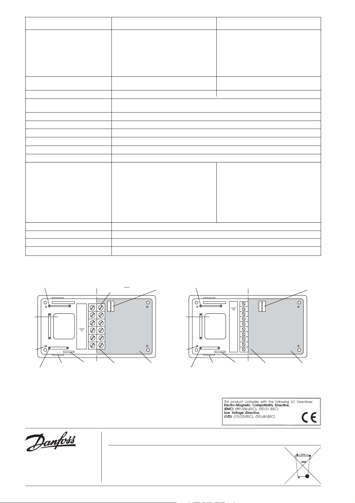
Aperture
for
cable
entry
4 fi xing
holes
2 cable
clamps
Alternative position
for cable clamp
THIS WAY UP
3 knockouts for
surface cable
entry
MODEL 841 MODEL 842
Spare
N
L
1
2
Rating and
model label
Do not slacken the
C/L
screws on this side of
the terminal block
Terminal block Do not route
Danfoss Randall can accept no responsibility for possible errors in catalogues, brochures and other printed material. Danfoss Randall reserves
the right to alter its products without notice. This also applies to products already on order provided that such alterations can be made without
subsequent changes being necessary in specifi cations already agreed.
Polarised
plug
surface mounted
cables through
shaded area
Aperture
for
cable
entry
4 fi xing
holes
2 cable
clamps
Alternative position
for cable clamp
THIS WAY UP
3 knockouts for
surface cable
entry
Spare
N
L
6
5
4
3
2
1
Rating and
model label
C/L
Polarised
plug
Terminal block Do not route
surface mounted
cables through
shaded area
Danfoss Randall Ltd,
Ampthill Road,
Bedford MK42 9ER
Tel: (01234) 364621 Fax: (01234) 219705
Email: danfossrandall@danfoss.com
Website: www.danfoss-randall.co.uk
2
Part No: 3262 Issue 5 12/05
 Loading...