

Page 1
811 & 851
}
}
Seven Day Single Channel Electronic Timeswitch
INSTALLATION INSTRUCTIONS
The Model 811 or 851 timeswitch must be installed by
a competant electrician and the installation should
conform to IEE Wiring Regulations.
Installation & Wiring
1. Slacken the four fi xing screws, one in each corner of the
unit, and carefully separate the front and rear portions.
Unplug the ribbon cable from the rear portion.
CAUTION: Do not allow either half of the unit to hang
by the ribbon cable as damage could be caused.
2. Remove the polystyrene packing piece from the top of
the transformer. It is marked ‘REMOVE’.
3. Select the desired fi xing position and observe the label
‘THIS WAY UP’ inside the rear portion. The two halves will
only assemble correctly one way round.
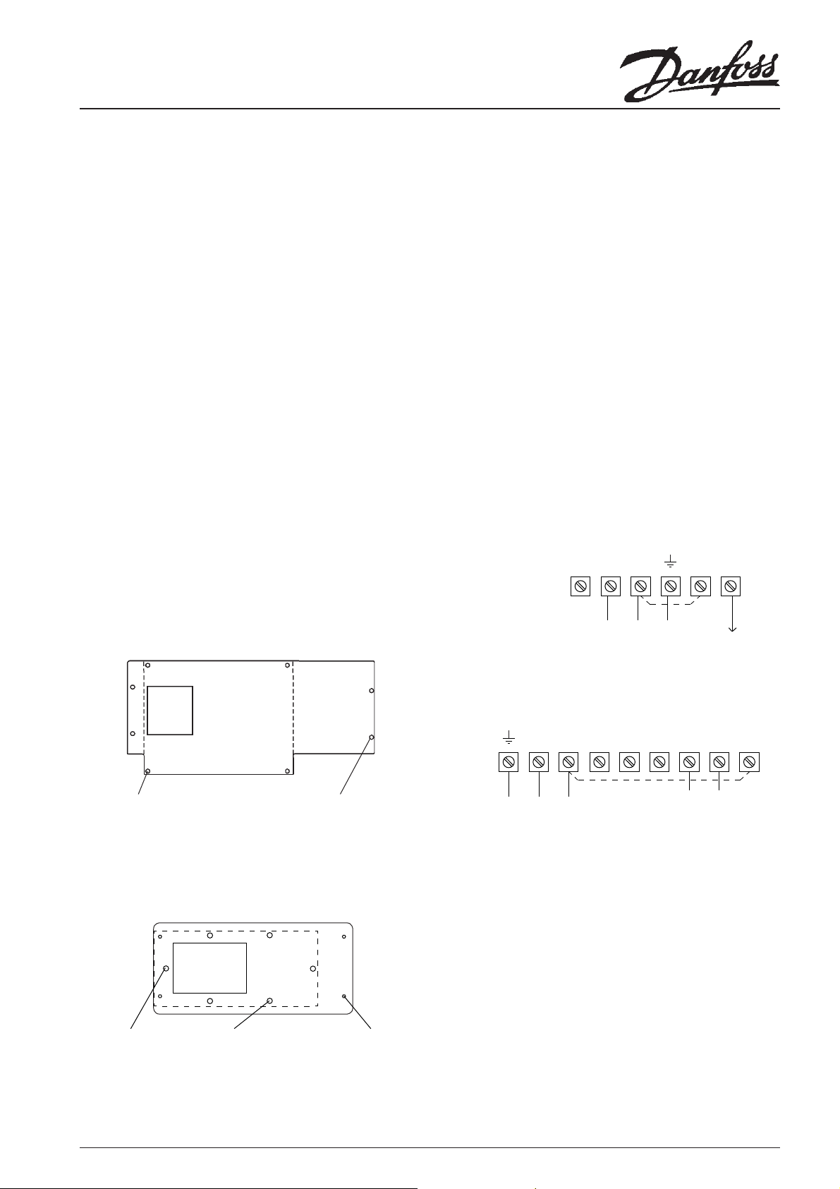
4. Four fi xing holes are provided for attaching the rear
portion to the wall or mounting surface.
Conduit box adaptors as shown below are available if
required.
5. Surface cable entries to the units can be made from
above, below or from the left hand side. Conduit or
recessed cable entry is through the aperture in the rear
moulding.
6. For surface cable entry remove the appropriate knockout and ensure one of the two cable clamps is positioned
correctly.
7. Connections to the units should be made as shown
below.
Model 811
Spare N L 1 2
Part No.: 8/3222 Square Conduit Box Adaptor
Cable
Entry
Aperture
4 fi xings for
existing square
conduit box
Part No.: 8/3223 Double Gang Surface Box Adaptor
Cable
Entry
Aperture
2 fi xings for
double gang
surface box
Alternative 4 fi xings
for double gang
surface box
4 fi xings
for mark 8
timeswitch
4 fi xings
for Mark 8
Timeswitch
Link for 240V
}
240V, 50 Hz
Model 851
N L 6 5 4 3 2 1
240V, 50 Hz
Mains Supply
If the control circuit(s) are to operate at 240V then
terminals L & 1 must be linked, ensuring that the cable is
sheathed and of a size to carry the required load current.
If, however, the control circuit(s) are operating at other
than 240V then no link(s) should be fi tted and in the
case of Model 811 both terminals 1 and 2 should be
connected to the load circuit; for Model 851 terminals
1, 2, and 3 (if required) should be connected to the load
circuit.
8. Upon completion of wiring plug in the ribbon cable
ensuring the polarised plug is fully inserted into socket,
refi t the front half of the timeswitch ensuring the correct
alignment and that no cables are trapped before retightening the screws.
Mains Supply
Link for 240V
control circuit
control circuit
OFF ON
LOAD
Output
(LOAD)
1
Page 2
Technical Specifi cation Model 811 Model 851
Power Supply 220/240Vac, 50/60Hz
Switch Action 1 x SPST, type 1 B (volt free) 1 x SPDT, type 1 B (volt free)
Switch Rating 220/240Vac, 50/60Hz, 30(10)A 220/240Vac, 50/60Hz, 10(4)A
Setting and Running Accuracy +/- 1 min and +/- 1min/month
Power Reserve 3 month on fully charged battery
Max number of programmable operations up to 200 ON or OFF operations per week
Enclosure Rating IP30
Max Ambient Temperature 45°C
Overall Dimensions 228mm wide, 115mm high, 50mm deep
Control Pollution Situation Degree 2
Software Classifi cation Class A
Designed to meet BS EN60730-2-7
Rated Impulse Voltage 2.5kV
Ball Pressure Test 75°C
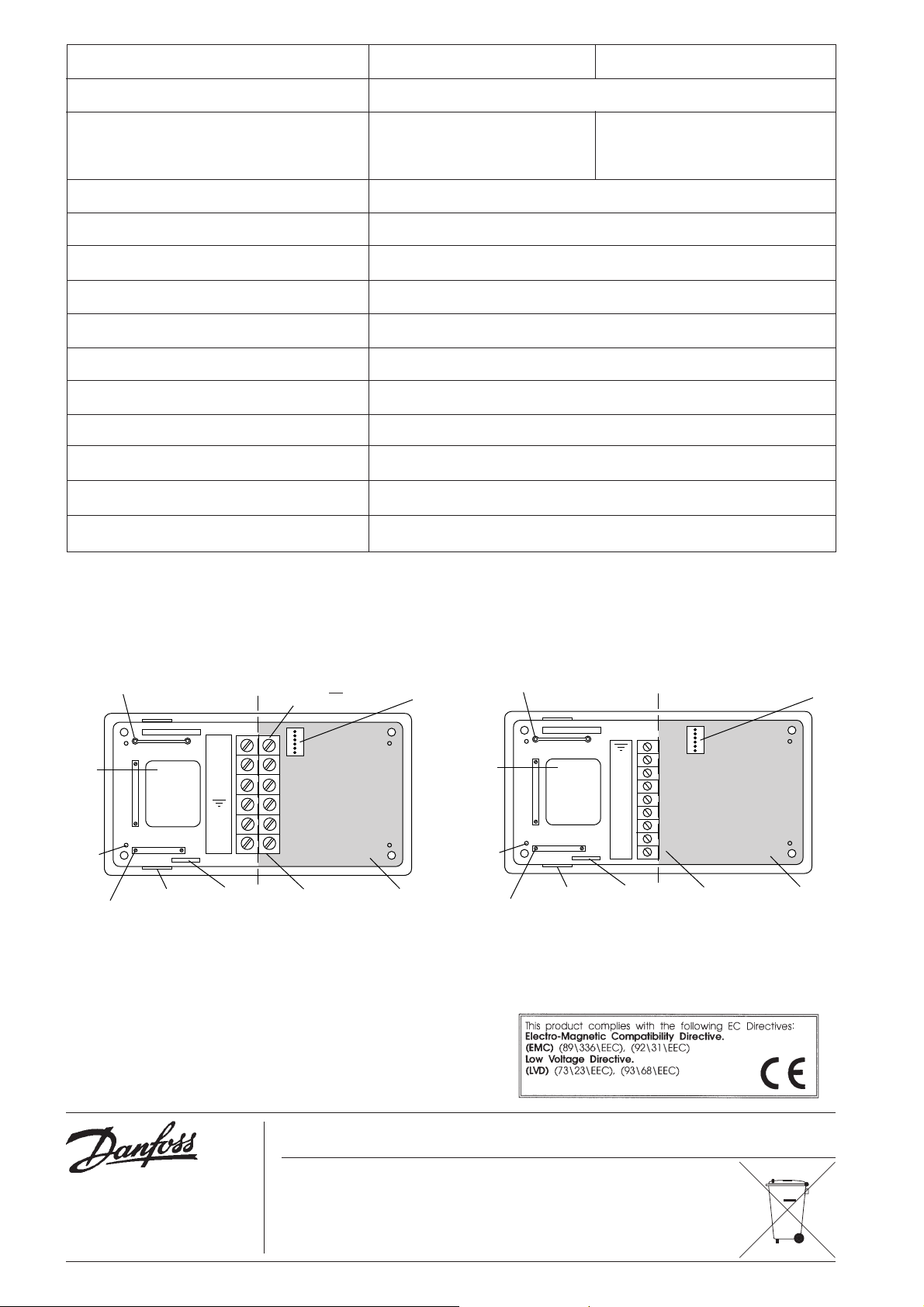
Model 811
Alternative position
for cable clamp
Aperture
for
cable
entry
4 fi xing
holes
2 cable
clamps
THIS WAY UP
3 knockouts for
surface cable
entry
Spare
N
L
1
2
Rating and
model label
Do not slacken the
C/L
screws on this side of
the terminal block
Terminal block Do not route
Polarised
plug
surface mounted
cables through
shaded area
Model 851
Alternative position
for cable clamp
Aperture
for
cable
entry
4 fi xing
holes
2 cable
clamps
THIS WAY UP
3 knockouts for
surface cable
entry
N
L
6
5
4
3
2
1
Rating and
model label
C/L
Terminal block Do not route
Polarised
plug
surface mounted
cables through
shaded area
Danfoss Randall can accept no responsibility for possible errors in catalogues, brochures and other printed material. Danfoss Randall
reserves the right to alter its products without notice. This also applies to products already on order provided that such alterations can
be made without subsequent changes being necessary in specifi cations already agreed.
Danfoss Ltd,
Ampthill Road,
Bedford MK42 9ER.
Tel: (01234) 364621 Fax: (01234) 219705
Email: ukheating@danfoss.com
Website: www.heating.danfoss.co.uk
2
Part No: 3046 Issue 9 12/05
 Loading...