

Page 1

Instruction Bulletin
Series 90 Intrinsically Safe Control
Installation, Maintenance
Intended Use
This line of Intrinsically Safe Pressure Control Pilots receives a low current input signal from a variety of machine controllers and
converts the current signal into a proportional differential pressure signal suitable to control larger hydraulic equipment in hazardous
locations. The Intrinsically Safe Controls can be added to a Series 90 pump as a standard option or purchased separately.
Danfoss offers five different models of Intrinsically Safe Pressure Control Pilots to accommodate a variety of standard industrial
process controllers. Various combinations of hydraulic nozzle sizes and coil resistances yields a relationship between electrical current
(input) and hydraulic differential pressure (output).
Refer to the Unit Specifications tables on pages three and four for proper selection.
Installation
Mechanical installation
Ensure that the four supplied O-rings are in place on the bottom of the unit. These pressure control pilots are fastened to the second
stage of the control with four M5 x 0.8 x 16 mm socket head screws. Torque to 5 Nm (44 in-lb).
Electrical Installation
A Mil-Spec Connector (MS3102C-14S-2P) provides the means for electronic signal input to the device. Proper selection of the mating
connector to ensure safe operation in a hazardous environment is required (Recommended MS3108E-14S-S, Danfoss Kit number
K08106). A suppression circuit is incorporated in the PCP torque motor cover but by itself does not insure intrinsic safety. An additional
safety barrier used to connect intrinsically safe circuits with non-intrinsically safe circuits must be connected in series between the
PCP and controller. The safety barrier and electrical controller must be isolated from the hazardous area either through use of a purge
enclosure or mounted in a safe area. The intrinsically safe device enclosure grounding terminal must be connected to a robust chassis
ground. The connection must be in accordance with applicable standards where required.
© Danfoss A/S, 2021
11129582 • AN152886481060en000303 •
February 2021
1
Page 2
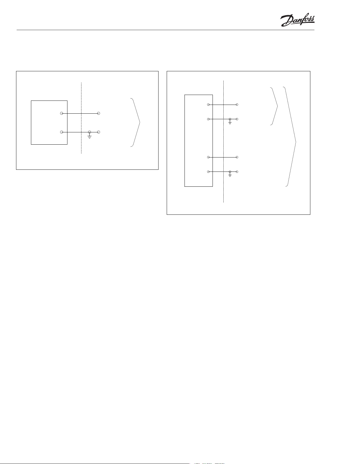
Refer to the following wiring diagrams for proper connections.
Wiring diagram for 11101116 Wiring diagram for 11101126, 11101118, 11101115, 11101106
Hazardous location
A
PCP
B
Exi Cl I, Div 1, Gp CD T4
Ex ia / AEx ia IIB T4 Ga
FM12ATEX0031X II 1 G Ex ia IIB T4 Ga
IECEx FMG 15.0008X Ex ia IIB T4 Ga
Non-hazardous location
V = 16.0 V
I = 110mA
P = 440mW
C = 0.4 µF
L = 0 mH
Adjustment
No adjustment is possible.
Do not attempt to disassemble or adjust the control.
Hazardous location
A
B
Single coil
PCP
C
D
Exi Cl I, Div 1, Gp CD T4
Ex ia / AEx ia IIB T4 Ga
FM12ATEX0031X II 1 G Ex ia IIB T4 Ga
IECEx FMG 15.0008X Ex ia IIB T4 Ga
Non-hazardouz location
V = 8.6 V
I = 250mA
P = 537.5mW
C = 0.4 µF
L = 0 mH
V = 8.6 V
I = 250mA
P = 537.5mW
C = 0.4 µF
L = 0 mH
Single coil
Dual coil
Putting into service
For instructions on putting a pump with the Intrinsically Safe Control in service, refer to Initial Startup Procedure in the Series 90 Pumps
Service Manual, AX152886483063.
Prior t
o installation, inspect packaging and unit for any damage. Do not continue installation if unit has visible signs of damage.
Danfoss is not responsible for the design of the control input circuit outside of the installed Mil-Spec connector. Proper design
on the entire system as noted in the applicable standards is required for safe usage in hazardous environments.
The condition of use
The EDC is designed to be controlled from a DC current source or voltage source. Pulse width modulation (PWM) is not required. But, if
a PMW signal is used, use a carrier frequency between 200 Hz and 4000 Hz. Do not use a pulse current of more than 120% of that
required for full output(refer to unit specifications below).
2
11129582 • AN152886481060en000303 •
February 2021
© Danfoss A/S, 2021
Page 3

A
C
Single coil
P108 686E
Unit specification tables
Pulse Width Modulation
(PWM) The PCP is designed to be controlled from a dc current source or voltage source. If a PWM signal is used, do not use a pulse
current of more than 120% of that required.
Coil resistance
Electrical Characteristics
Single Coil
Coil Resistance
Dual Coil
Coil Resistance
Positive voltage to pin
A produces a pressure
Phasing
rise at output port C1
Positive voltage to pin
B produces a pressure
rise at output port C2
AB
Dual coil
B
D
Model Number
11101126 11101118 11101116 11101115 11101106
A-B 23 Ω at 70° F,
A-B 29 Ω at 200° F
A-B 23 Ω at 70° F,
A-B 29 Ω at 200° F
Positive voltage to pin
A produces a pressure
rise at output port C1
Positive voltage to pin
B produces a pressure
rise at output port C2
A-B 106 Ω at 70° F,
A-B 130 Ω at 200° F
Positive voltage to pin
A produces a pressure
rise at output port C1
Positive voltage to pin
B produces a pressure
rise at output port C2
A-B 20 Ω at 70° F,
A-B 25 Ω at 200° F
C-D 16 Ω at 70° F,
C-D 20 Ω at 200° F
Positive voltage to
pin A or C produces a
pressure rise at output
port C1 Positive
voltage to pin B or D
produces a pressure
rise at output port C2
A-B 20 Ω at 70° F,
A-B 25 Ω at 200° F
C-D 16 Ω at 70° F,
C-D 20 Ω at 200° F
Positive voltage to
pin A or C produces a
pressure rise at output
port C1 Positive
voltage to pin B or D
produces a pressure
rise at output port C2
Current/Voltage Range
Scale Factor
© Danfoss A/S, 2021
up to 145 mA at 3.90
Vdc (linear range)
0.165 ± 0.013 Bar/mA
2.4 ± 0.2 psid/mA
11129582 • AN152886481060en000303 •
up to 190 mA at 4.75
Vdc (linear range)
0.079 ± 0.007 Bar/mA
1.15 ± 0.1 psid / mA
4 mA at 0.50 Vdc
to 20 mA at 2.2 Vdc
(linear range)
0.379 ± 0.034 Bar/mA
5.5 ± 0.5 psid / mA
February 2021
up to 205 mA at 4.50
Vdc (linear range)
0.101 ± 0.010 Bar/mA
1.47 ± 0.15 psid / mA
up to 170 mA at 4.50
Vdc (linear range)
0.054 ± 0.006 Bar/mA
0.78 ± 0.08 psid / mA
3
Page 4

Unit specification tables
Hydraulic Fluid
Oil Viscosity must be in the 40 – 6000 SSU [cSt] range.
Oil Cleanliness of ISO 4406 class 22/18/13 (SAE J1165) or better, under normal operating conditions.
For detailed information on lubricants and cleanliness refer to Hydraulic Fluids and Lubricants BC1528864845240463, and Design
Guidelines for Hydraulic Fluid Cleanliness BC152886482150.
Hydraulic Characteristics
Model Number
11101126 11101118 11101116 11101115 11101106
Maximum supply pressure:
69 bar
1000 psid
69 bar
1000 psid
69 bar
1000 psid
69 bar
1000 psid
69 bar
1000 psid
Recommended range:
Maximum return pressure:
Maximum internal leakage:
at 500 psid supply
Maximum linear psid output
pressure:
Load flow: the output
dierential flow across a 100
psid load pressure drop at
maximum current:
27.6 - 41.4 bar
400 - 600 psid
13.8 bar
200 psid
3.41 lpm
0.90 gpm
24.1 bar at
34.5 bar supply
350 psid at
500 psid supply
>0.738 l/m
> 45 cim
20.7 - 34.5 bar
300 - 500 psid
13.8 bar
200 psid
2.46 lpm
0.65 gpm
15.2 bar at
20.7 bar supply
220 psid at
300 psid supply
>0.0492 l/m
> 30 cim
20.7 - 34.5 bar
300 - 500 psid
13.8 bar
200 psid
2.46 lpm
0.65 gpm
15.2 bar at
20.7 bar supply
220 psid at
300 psid supply
>0.0492 l/m
> 30 cim
34.5 - 41.4 bar
500 - 600 psid
13.8 bar
200 psid
2.46 lpm
0.65 gpm
21.4 bar at
34.5 bar supply
350 psid at
500 psid supply
>0.738 l/m
> 45 cim
20.7 - 34.5 bar
300 - 500 psid
13.8 bar
200 psid
2.46 lpm
0.65 gpm
13.8 bar at
20.7 bar supply
220 psid at
300 psid supply
>0.0492 l/m
> 30 cim
4
11129582 • AN152886481060en000303 •
February 2021
© Danfoss A/S, 2021
Page 5

Maintenance, Overhaul, and Repair
Caution
Part of the enclosure is constructed from plastic. To prevent the risk of electrostatic sparking the plastic surfaces should only be cleaned
with a damp cloth.
No other maintenance is required.
For overhaul or repair return to:
Danfoss Power Solutions
2800 East 13th Street
Ames IA, 50010
A List of Standards to which the Product
was Assessed
For the U.S.
FM3600: 2011; FM3610: 2010; FM3810: 2005; ANSI/IEC 60529: 2004; ANSI/ISA 60079-0: 2009; ANSI/ISA 60079-11: 2011;
For Canada
CAN C22.2 No. 157-92:1992; C22.2 No. 1010.1:2012; CSA-C22.2 No. 60529:2005; CAN/CSA E60079-0:2011; CAN/CSA E60079-11:2011
For ATEX
EN60079-0:2012; EN60079-11:2012; En 60529:1991+Amendment :2000
For IEC
IEC 60079-0:2011 Edition 6; IEC 60079-11 Edition 6
Labels
11101126, 11101118, 11101115, 11101106
Intrinsically Safe / Sécurité intrinséque
Exi, Cl I, Div 1, Gp CD T4
Ex ia / AEx ia IIB
FM12ATEX0031X II 1 G Ex ia IIB T4 Ga
IECEx FMG 15.0008X Ex ia IIB T4 Ga
Install per control drawing: DWG00019588
MODEL NO.
XXXXXXXXXXX
DANFOSS POWER SOLUTIONS (US) COMPANY, 2800 E. 13th St. Ames, IA 50010
Input: 8.6 VDC; 250mA
11101116
Intrinsically Safe / Sécurité intrinséque
Exi, Cl I, Div 1, Gp CD T4
Ex ia / AEx ia IIB
FM12ATEX0031X II 1 G Ex ia IIB T4 Ga
IECEx FMG 15.0008X Ex ia IIB T4 Ga
Install per control drawing: DWG00019589
MODEL NO.
XXXXXXXXXXX
DANFOSS POWER SOLUTIONS (US) COMPANY, 2800 E. 13th St. Ames, IA 50010
Input: 16 VDC; 110mA
T4 Ga
2809
IP66
Made in USA
S/N: A123456789
T4 Ga
2809
IP66
Made in USA
S/N: A123456789
© Danfoss A/S, 2021
11129582 • AN152886481060en000303 •
February 2021
5
Page 6

Danfoss A/S
Teleph
EU DECLARATION OF CONFORMITY
Danfoss A/S
Danfoss Power Solutions
declares under our sole responsibility that the
Product: Pressure Controlled Pilot Valve
Models: 11101106, 11101115, 11101118, 11101126, and 11101116
Description: Receives a low current input signal from a variety of machine controllers and converts the
current signal into a proportional differential pressure signal suitable to control larger
hydraulic equipment
DK-6430 Nordborg
Denmark
CVR nr.: 20 16 57 15
one: +45 7488 2222
Fax: +45 7449 0949
2809
Ex ia IIB T4 IP 66
FM12ATEX0031X
II 1 G
covered by this decl aration is in conformity with the following directive(s), standard(s) or other
normative document(s), provided that the product is used in accordance with our instructions.
Directive Title
2014/34/EU Equipment for Potentially Explosive Atmospheres (ATEX)
Reference Number Title
EN 60079-0:2012 + A11:2013 Explosive Atmospheres – Part 0: Equipment – General requirements
EN 60079-11:2012 Explosive Atmospheres – Part 11: Equipment protection by intrinsic safety “i”
EN 60529:1991 + A1:2000 Degrees of Protection Provided by Enclosures (IP Code)
Notes:
The pressure controlled pilo t valve must be used in accordance with its specifications, especially (but not
limited to) electrical, pressure, temperature, shock, and vibration limits.
FM Approvals, Ltd. Notified Body n o.:
2809
6
Date Issued by Date Approved by
Signature
Name
Title
Danfoss only vouches for the correctness of the English version of this declaration. In the event of the declarationbeing translated into any other
language, the translator concerned shall be liable for the correctness of the translation
11129582 • AN152886481060en000303 •
Signature
Name
Title
February 2021
© Danfoss A/S, 2021
 Loading...