

Page 1

Instructions
8238-17
6
6
8385-9
9
12
10
8
7
8
M
f
2
3
4
5
1
L
N
N
C
C
L
N
R+
R-
11
7
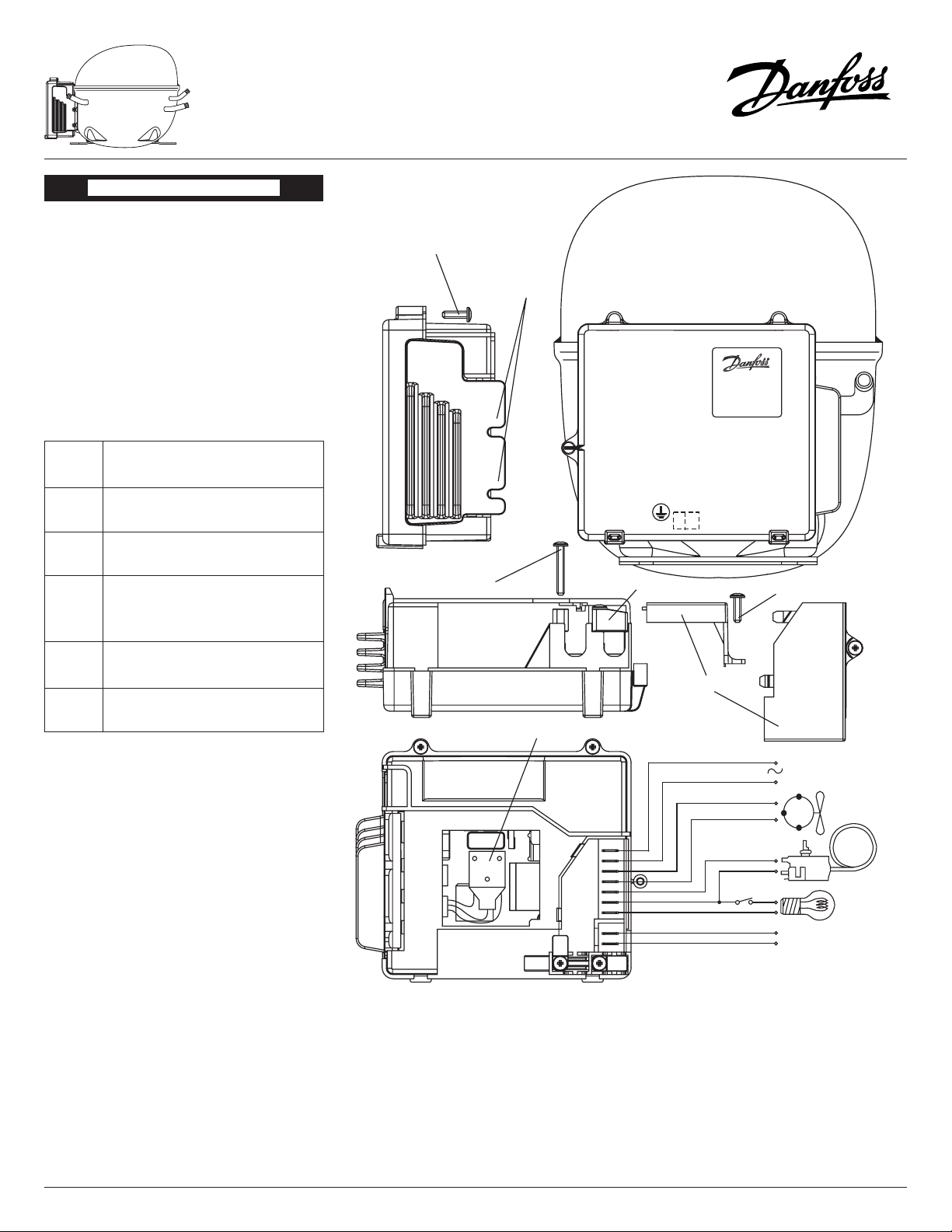
Electronic Unit Type 105N4210 & 105N4212,
80-140V, 50-60Hz for NLV Compressors
ENGLISH
The electronic unit is working in an AC voltage range of
80-140V. Max. allowable ambient temperature is 43°C.
The electronic unit is provided with a built-in thermal
protection which stops the compressor in case of
thermal overload.
1. Installation
The connec tor (11) of the electronic unit (9) has to
be connected to the compressor (12) rst. The total
unit then is assembled by putting on the housing.
Furthermore, screws with toothed washers must be
mounted to the compressor through the recesses in
the heatsink unit (6). All other terminals (except the
earth connection under point 6) and cord relief (8) are
under the cover (7).
2. Power supply
Power supply L and N:
Power supply (1) is connected to L and N. Earth connection is connected to terminal on the compressor
housing (12).
3. Fan
Fan N and C:
A fan (2) can be connected to N and C. It will be
operated with power line voltage, and cut in and out
with the compressor if a conventional thermostat is
used.
4. Thermostat connection (3) light connection (4)
The unit has 3 connection options for thermostats.
4.1 Voltage signal application "on - o" (conventional thermostat)
Thermostats C, L and N:
Compressor control is an "adaptive control", see description under point 5.
4.2 Application of a thermostat provided with DC
signal out (min. 5V, max. 15V)
Signal input R+ and R- (5)
(fan connection not possible):
Connection with DC signal "on - o" to control unit,
with reinforced isolation in control unit (5).
The compressor unit runs in "adaptive control" mode,
see description under point 5.
4.3 Application of an electronic thermostat with
frequency output (min. 5V, max. 15V)
Signal input R+ and R- (5)
(fan connection not possible):
The refrigerator thermostat has to supply the control
unit (9) with a square signal (min. pulse width 200 µs).
The input terminals are reinforced isolated. If the frequency is more than 100 Hz the compressor goes into
"external reference control" mode. The compressor
speed is controlled by the external frequency ("adaptive control" is disabled). The control unit remains in
this mode until the power supply is disconnected. The
compressor stops with an input signal below 198 Hz
(min. 196 Hz, max. 199 Hz). Compressor operation: if
a frequency of above 203 Hz (min. 201 Hz, max. 205
Hz) is supplied, the compressor starts. Example for
compressor speed: external frequency multiplied by
10 (270 Hz => 2,700 rpm). If a signal with a frequency
according to a speed above maximum is applied, the
compressor works at maximum speed.
Visit our Homepage: compressors.danfoss.com 1/2 DEHC.PI.300.A1.22/520N0420 01-2007
If a DC signal is supplied immediately after a frequency
signal, the compressor speed is locked until another
frequency is applied or the DC signal is removed.
5. Adaptive control
(AEO - Adaptive Energy Optimizer)
The compressor adjusts its speed in steps to any increasing or decreasing cooling demand, within the
minimum and maximum speed limits. If the thermostat switches the compressor "ON": After a 60-minute
running time, the speed will increase stepwise every
15 minutes, depending on the latest speed used, until
the maximum is reached. If the thermostat switches
the compressor "OFF": After each "ON", the compressor
either restarts with lower speed steps than the recently
used, until the minimum is reached, or increases its
speed stepwise, after a new 60-minute running time.
6. Earth connection
Earth connector to be applied to compressor housing
(10). The electronic unit is protected by the electrical
connection heatsink - toothed washer - screw - compressor housing.
Page 2
Electronic Unit Type 105N4210 & 105N4212,
8238-17
8385-5
M
f
L
N
N
C
C
L
N
R+
R-
Compressor
Power supply
Fan
connect.
Thermostat
connect.
Light
connect.
Signal input
Mounting
recesses
Cover
Cord relief
Electronic unit
Earth connection
Connector
Screw 3.5x25 mm
Screw 3.5x12 mm
Screw 3.5x12 mm
80-140V, 50-60Hz for NLV Compressors
ENGLISH
7. Troubleshooting
To diagnose why the compressor comes to an unintended stop, it is recommend to have a Light Emitting
Diode (LED) on the PCB board.
Provided that the electronic unit is properly connec-ted
to the power supply, the number of ashes emitted by
the LED will give a hint about the reason for the interruption of the compressor operation.
The motor windings can be checked for defects by
measuring the resistance between the current lead-in
pins. If the measured values between all 3 pins are
approximately the same, the motor is most likely all
right.
The electronic unit is not to be repaired. It should not
be opened at all.
Instructions
Number
of
ashes
1 Under voltage
(The supply voltage is below 80V AC).
2 Over speed
(The compressor speed was above 7100 RPM).
3 Under speed
(If the refrigeration system is too heavily loaded,
the motor can’t maintain min. speed at approximately 1850 RPM).
4 Thermal cut-out
(If the refrigeration system has been too heavily
loaded, or the ambient temperature is too high).
5 Start error
(More than 5 start attempts).
Error type
Visit our Homepage: compressors.danfoss.com 2/2 DEHC.PI.300.A1.22/520N0420 01-2007
 Loading...