

Page 1
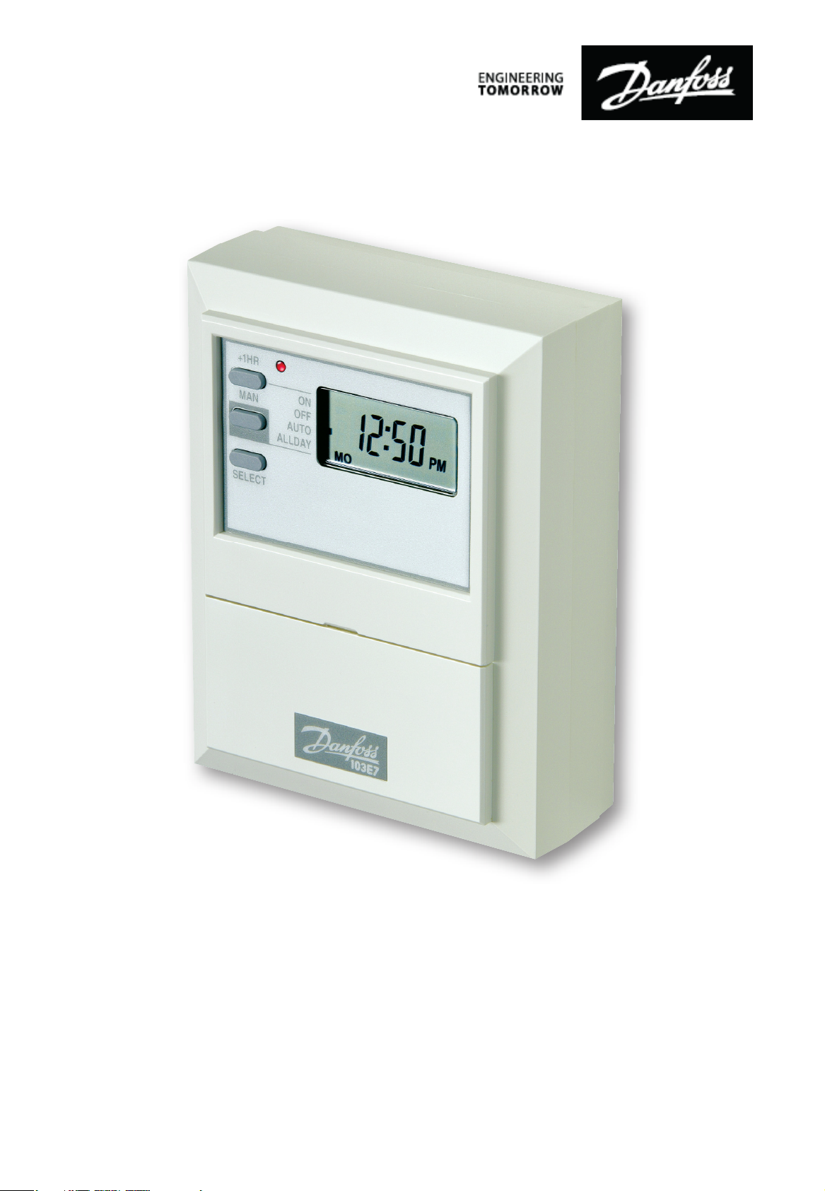
103E7
7-Day Electronic Timeswitch
for Controlling Hot Water and Heating
(Including Factory Replacement Units FRU)
Danfoss Heating
Installation Guide
Page 2

GB
For a large print version of these instructions
please call Marketing on 01234 364 621.
®
Certification Mark
Danfoss can accept no responsibility for possible errors in catalogues, brochures, and other
printed material. All trademarks in this material are property of the respective companies.
Danfoss and the Danfoss logotype are trademarks of Danfoss A/S. All rights reserved.
2
103E7
Page 3
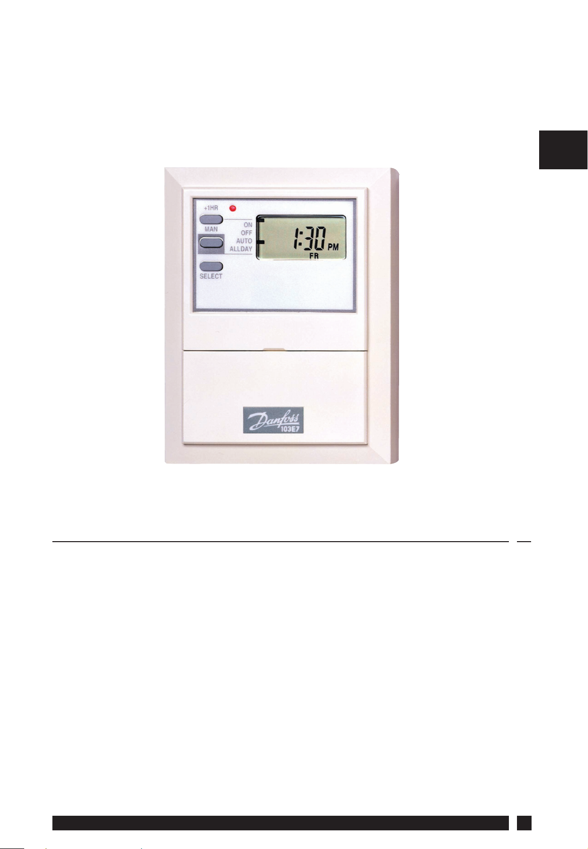
103E7
7-Day Electronic Timeswitch
for Controlling Hot Water and Heating
GB
Index
1.0 Installation Overview .............................................................................. 4
2.0 Product Speci cation ..............................................................................4
3.0 Installation ...................................................................................................4
3.1 Wiring .....................................................................................................6
4.0 Replacement ............................................................................................. 10
Danfoss Heating
3
Page 4
1.0 Installation Overview
Please Note:
This product should only be installed by a quali ed electrician or
competent heating installer and should be in accordance with the
GB
current edition of the IEEE wiring regulations.
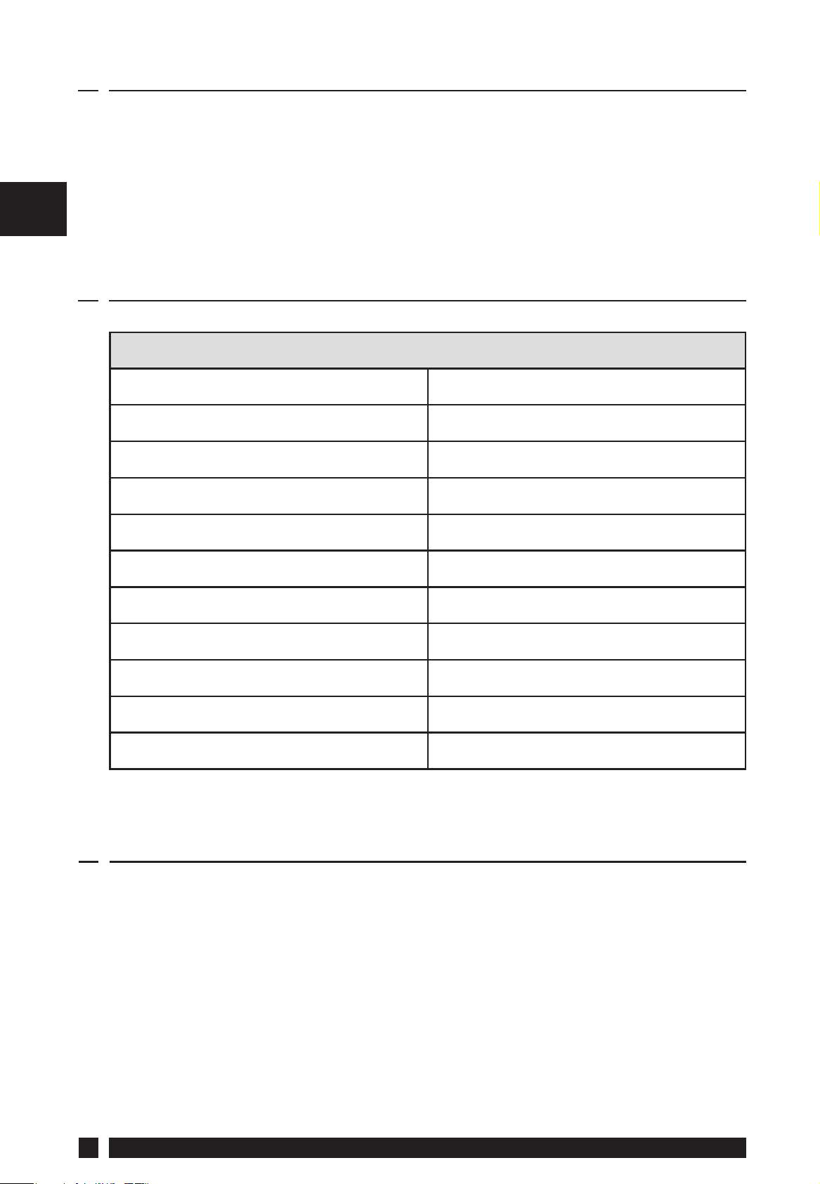
2.0 Product Speci cation
Speci cation
Power Supply 230Vac, ± 15%, 50 Hz
Switching Action 1 x SPST, Type 1B
Switch Rating 264Vac, 50/60Hz, 3(1)A
Setting/Running Accuracy ±1 min./month
Power Reserve Minimum 24 hours
Max. Ambient Temperature 45°C
Dimensions, mm (W, H, D) 102 x 136 x 47
Design Standard EN 60730-2-7
Control Pollution Situation Degree 2
Rated Impulse Voltage 2.5kV
Ball Pressure Test 75°C
3.0 Installation
NB. For FRU units - go straight to point 6.
1. Loosen the xing screw in the base of the unit to release the
Wiring Cover.
2. Holding the unit face downwards, press rmly in the centre of
the wallplate and slide it apart and lift it from the module.
4
103E7
Page 5

3. Fix the wallplate and terminal block to the wall, or plaster box, as
required. Ensure that the screw heads do not protrude beyond
the vertical centre rib of the wallplate, or this will prevent the
module correctly locating onto the wallplate.
Screw xing holes
(screwheads MUST NOT
Vertical
centre rib
protrude above centre rib)
Wallplate & Terminals
GB
4. Surface cables can only enter from below the unit. Cut an
appropriate cable aperture in the wiring cover. If the wallplate is
mounted on a plaster box, cables can enter from the rear below
the terminal block.
5. Electrical connections are simpli ed by using a Wiring Centre.
However, if this is not used, the wallplate terminal identi cation
is as shown.
Load Mains Supply (via 3 amp fuse)
ON SPARE COM N L
123 5 6
If the system being controlled is 230 Vac, then terminals 3 and L
must be linked with insulated cable capable of carrying full load
current. Whilst the unit does not require an earth connection,
a terminal is provided on the wallplate for earth continuity
purposes.
6. Refer to the wiring diagrams on page 6-9, connect the unit as
shown.
Danfoss Heating
5
Page 6

GB
7. Find out from the user whether the unit is required to operate
in 7-day mode (factory preset) or weekday/weekend mode
(5/2 day). To convert to 5/2 day mode remove the small twoway connector from the pins towards the left of the recess on
the rear of the module, then press the button marked R/S under
the ap to RESET the unit.
8. Ensure all dust and debris are cleared from the area. Plug the
module into the wallplate by locating it onto the wallplate and,
when ush with it, sliding it down, ensure the hook at the top of
the wallplate engages with the slot at the back of the module.
9. Before setting the programme, check the unit and circuit. Press
the SELECT button until the bar in the display lines up with the
word ON. Adjust the remote thermostats to check the system
operates correctly.
10. Then press the SELECT button until the bar lines up with the
word OFF and check the system does not operate.
11. When the circuit check has been completed, replace the wiring
cover and tighten the xing screw. Cut any cable aperture in the
wiring cover which may be necessary to accommodate surface
mounted cables.
12. Finally set time of day and programmes required, noting that
the unit is supplied with a pre-set programme, see User Guide.
3.1 Wiring
6
103E7
Page 7

Typical Gravity DHW with Pumped Heating
1
COM
L N
ROOM
' STAT
23
LINK
CALL
N
BOILER
TERMINALS
56
L N
103E5
103E7
TERMINALS
TERMINALS
L
MAINS
SUPPLY
N
FUSED
3 AMP
PUMP
TERMINALS
GB
Typical Control of Pump for Central Heating
on a Solid Fuel System
3
LINK
5
6
103E5
103E7
TERMINALS
TERMINALS
L
MAINS
SUPPLY
N
FUSED
3 AMP
COM
1
ROOM
' STAT
2
CALL
N
Danfoss Heating
L N
PUMP
TERMINALS
7
Page 8

Typical Heating Only System,
Boiler and Pump Control
GB
1
COM
L N
ROOM
' STAT
23
LINK
CALL
N
BOILER
TERMINALS
56
L N
103E5
103E7
TERMINALS
TERMINALS
L
MAINS
SUPPLY
N
FUSED
3 AMP
PUMP
TERMINALS
Typical Control of Low Voltage System requiring
Voltage Free Contacts
1
COM
VOLTAGE
2
CALL
LOW
ROOM
' STAT
3
56
103E7
103E5
TERMINALS
TERMINALS
L
N
MAINS
SUPPLY
FUSED
3 AMP
LOW
LOAD
8
VOLTAGE
SUPPLY
103E7
Page 9

Typical control of Heating when provided by
Combination type Boiler (see note below)
COM
1
ROOM
' STAT
23
CALL
N
INPUT
OUTPUT
56
103E7
TERMINALS
NL
COMBI BOILER
TERMINALS
103E7
TERMINALS
L
MAINS
SUPPLY
N
FUSED
3 AMP
GB
Note: Connection must only be made if input/output of boiler are
230V signals
Typical Heating and Hot Water Control System
using 3 Port Mid-position Valve
1
ROOM
' STAT
23
CYL.
' STAT
N
SAT
LINK
COM
CALL
56
103E7
103E5
TERMINALS
TERMINALS
L
N
MAINS
SUPPLY
FUSED
3 AMP
WHITE
OR
BROWN
Danfoss Heating
BLUE
MID-POSITION VALVE
GREY
RED OR
ORANGE
BOILER &
PUMP
TERMINALS
L N
9
Page 10

GB
terminated
An additional terminal block is
leads (or pairs of leads) should be
required where these disconnected
MAINS SUPPLY
(via 3 amp fuse)
LIVE
MOTOR
N
LIVE
SWITCH
10
LOAD
DANFOSS
ON SPARE COM
1 2 3 5 (N) 6 (L) A B C D
RANDALL 103E7
RANDALL 103, 103E, 103E7 1 2 3 5 6
4 2 3 N L,1 5
RANDALL 3020 4 2 - 1,7 6 3 5
RANDALL TSR2 5 4 1 3 2 6 7
GRASSLIN 45, 45A, 45E 4 - 3 2 1
HORSTMANN 424 EMERALD
& PEARL AUTO RANGE
41 3 NL256
LOAD - - N L
HORSTMANN 423 PEARL,
EMERALD & TOPAZ
SANGAMO S254 Form 2,
S408 Form 5,
S251 Form 2
2 1 6 3,N 5,L
LOAD -
SANGAMO S610 F2,
S611 F2, S612 F2, S408 F4,
S408 F6, S253 F2, S255 F2
SANGAMO S409 Form 8
103E7
Page 11

terminated
GB
An additional terminal block is
leads (or pairs of leads) should be
required where these disconnected
MAINS SUPPLY
(via 3 amp fuse)
LOAD
ON SPARE COM
DANFOSS
RANDALL 103E7
Danfoss Heating
1 2 3 5 (N) 6 (L) A B C D
4,5 3 - 1 2 6
SANGAMO/RANDALL SET 1 4 2 5 N L
SMITHS IND. MKI, MKII P3 P1 P2 N L
SMITHS IND.
CENTROLLER 30
4,5 3 - 1 2
SMITHS IND.
CENTROLLER 40
SWITCHMASTER 300 1 2 4 N L 3
LOAD - LINE N L
TOWERCHRON TC 7 3 4 2 1 8 9 10 11
VENNER VENNERETTE MKIIA
1- 4 23
VENNER VENNERETTE MKIVA
4- 1 32
VENNER VENNERON
VENNERON P
11
Page 12

Danfoss Ltd.
Ampthill Road
Bedford MK42 9ER
Tel: 01234 364621
Fax: 01234 219705
Email: ukheating@danfoss.com
Website: www.heating.danfoss.co.uk
Part No. 2758v01 02/12
 Loading...