

Page 1

103
Electro-mechanical 24 hour
timeswitch for controlling hot water and heating
(Including Factory Replacement Units FRU)
Danfoss Heating
Installation and User Guide
Page 2

Index
Installation
Product speci cation 3
Installation 4-5
Wiring 6
User
What is a timeswitch? 7
Your timeswitch 8
Setting the time of day 9
Setting the programme 9-10
Selecting operating mode 11
Temporary overrides 12
Contact details 16
INDEX
For a large print version of these instructions
please call Marketing on 01234 364 621.
2
®
Certification Mark
Danfoss can accept no responsibility for possible errors in catalogues, brochures, and other printed
material. All trademarks in this material are property of the respective companies. Danfoss and the
Danfoss logotype are trademarks of Danfoss A/S. All rights reserved.
Page 3
Installation Instructions
Please Note:
This product should only be installed by a quali ed
electrician or competent heating installer, and should be
in accordance with the current edition of the IEEE wiring
regulations.
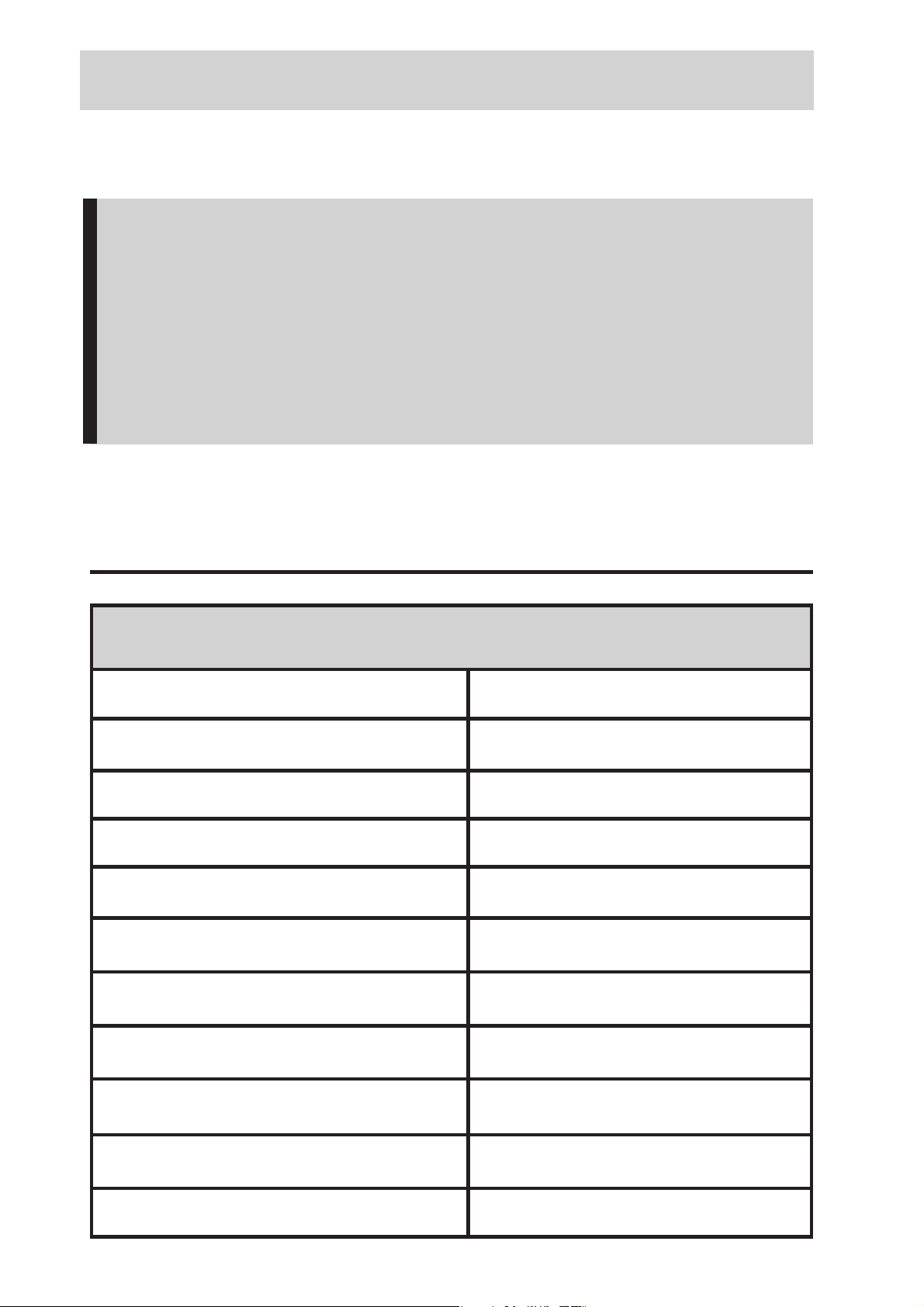
Product speci cation
Speci cation
Power supply 230 Vac ± 15%, 50 Hz
Switching action 1 x SPST, Type 1B
Max. Switch Rating 264Vac, 50/60Hz, 6(2)A
Timing Accuracy ±1 min./month
Enclosure Rating IP20
Max. Ambient Temperature 55°C
Dimensions, mm (W, H, D) 112 x 135 x 69
Design standard EN 60730-2-7
Installation & Speci cation
Control Pollution Situation Degree 2
Rated Impulse Voltage 2.5kV
Ball Pressure Test 75°C
3
Page 4
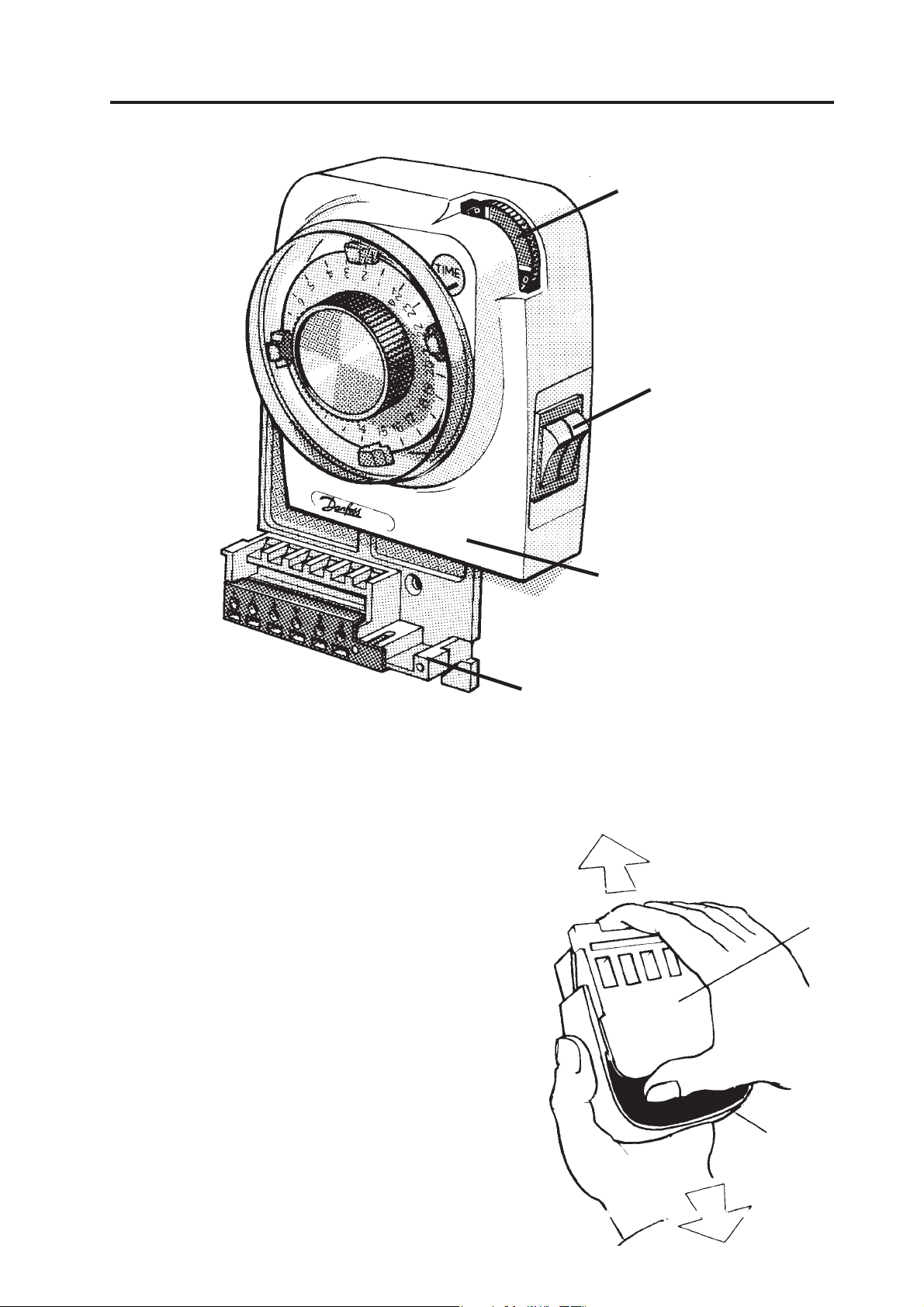
Installation
Pre-Selector wheel
Selector switch
Plug-in replacement
module
Wallplate/Terminal
block (not with FRU
units)
NB. For FRU units - go straight to to point 4 on page 5
1. Loosen the xing screw in the
base of the unit to release the
Installation
grey plastic Wiring Cover. Ensure
the protective tape over the
thumbwheel remains in place.
wallplate/
terminal
block
4
2. Holding the unit clockface
downwards, press rmly in the
centre of the wallplate and slide
it from the module as shown.
plug-in
module
Page 5

3. Fix the Wallplate/Terminal Block to the wall with
countersunk No.8 woodscrews or to a steel box to BS 4662.
1970 or a surface mounting steel or moulded box having
centres of 23/8” (60.3mm).
4. Referring to the Wiring Diagrams on page 6, connect the
unit as shown. Ensure that terminals 3 and 6 are linked
where required (Mains Voltage applications) with insulated
cable capable of carrying full load current.
5. Ensure all dust and debris has been cleared away from
the area, then plug the module rmly into the wallplate
ensuring that the hook at the top of the wallplate engages
with the slot at the back of the body. Press the module
down until it locates solidly.
6. Cut a cable aperture in the Wiring Cover if necessary;
replace the Wiring Cover, and tighten the xing screw.
7. Switch on Mains & test for correct operation as follows:
i) Remove protective tape from pre-selector wheel.
ii) Remove dial cover & rotate the clock dial two
complete revolutions to clear the mechanism.
ii) Check that all positions of the Selector Switch
and Tappets operate correctly. (See instructions
in User Booklet.)
Installation
8. Replace the dial cover. Finally leave this booklet, containing
the USER instructions with the Householder.
9. If the unit is to be left turned o and is in a dusty
atmosphere, protect the pre-selector wheel by re-a xing
the protective tape.
IMPORTANT: Remove tape prior to putting unit into
service
.
5
Page 6

Wiring
103, 103E5
TYPICAL EXTERNAL CIRCUITS
Wiring
103 Terminals
6
1
Com
N
Call
1) Control of Heating Function only
Note: If room thermostat is not required, join
timeswitch terminals 1 and 2 with a link
suitable for full load current).
3
2
Room
Stat
(Mains Voltage)
L N
Terminals
5
Link
Mains
Supply
Load
103 Terminals
6
1
3
2
5
103 Terminals
1
L
N
Low
voltage
room stat
2) Control of Low Voltage Systems
(e.g. warm air gas valves, low voltage
103 Terminals
1
6
3
2
Load
burners
3
2
5
Mains
Supply
Low voltage
supply/return
6
5
L
N
6
Link
Com
N
Call
L N
Boiler
Terminals
3) Typical gas or oil fired heating system
with gravity hot water primary and
Room
Stat
L N
Pump
Terminals
pumped heating
Mains
Supply
L
N
Com
N
Call
Room
Stat
Input Output
Boiler Terminals
4) Typical control of heating when used with
combination type boilers
N L
L
N
Mains
Supply
Page 7

The text below has been edited and approved
by the Plain English Campaign, who has issued a Crystal
Mark to be displayed with it.
What is a programmer?
... an explanation for householders.
Programmers allow you to set ‘On’ and ‘O ’ time periods.
Some models switch the central heating and domestic hot
water on and o at the same time, while others allow the
domestic hot water and heating to come on and go o at
di erent times.
Set the ‘On’ and ‘O ’ time periods to suit your own lifestyle.
On some programmers you must also set whether you want
the heating and hot water to run continuously, run under the
chosen ‘On’ and ‘O ’ heating periods, or be permanently o .
The time on the programmer must be correct. Some types
have to be adjusted in spring and autumn at the changes
between Greenwich Mean Time and British Summer Time.
You may be able to temporarily adjust the heating
programme, for example, ‘Override’, ‘Advance’ or ‘Boost’.
These are explained in the manufacturer’s instructions.
The heating will not work if the room thermostat has switched
the heating o . And, if you have a hot-water cylinder, the
water heating will not work if the cylinder thermostat detects
that the hot water has reached the correct temperature.
Please note:
A timeswitch is a single channel programmer. It will allow you to set
What is a programmer?
your system’s On and O periods.
7
Page 8

User Instructions
Your timeswitch
Your 103 timeswitch has one time output which can be used to
control your heating and hot water at the same times.
Normally the 103 provides 2 ON periods and 2 OFF periods each
day. However 1 ON and 1 OFF period can be obtained by using
the Pre-Selector Wheel (see page 12).
You can choose whether the 103 controls your hot water & heating
at the programmed times, constantly ON or constantly OFF.
Preselector wheel
Dial cover
Overview
8
Rocker
switch to
manually
select
programme
Wiring cover
operation
Page 9

Setting the time of day
The dial on the front of the 103 displays the hours of the day using
the 24hour clock.
Remove dial cover (turn
slightly to the left and pull
o )
Turn the dial clockwise
until the correct time is
aligned to the TIME mark
(as shown).
IMPORTANT: turn the dial clockwise only
Remember you will have to re-set the time after a power-cut,
and also when the clocks change in Spring and Autumn.
!
Setting the programme (Tappets A, B, C, D)
1. If not already done so, remove the dial cover (turn slightly
to the left & pull o )
Setting the time & the programme
2. Decide when you want your hot water and heating to come
on and go o . While gripping the dial knob slide the RED
tappets to the required ON times and the BLUE tappets to
the required OFF times (the tappets may be quite sti to
move)
9
Page 10

Example:
:
N
If you want your system ON between 8am and 10am and again
between 4pm and 11pm, set the tappets as shown. (A to 8, B to
10, C to 16, D to 23).
A = 1st ON
B = 1st OFF
C = 2nd ON
D = 2nd OFF
Remember:
Remember
Red tappets (A and C) switch ON
Red tappets (A and C) switch O
Blue tappets (B and D) switch OFF
Blue tappets (B and D) switch OFF
Setting the programme
3. Ensure that the installer has removed the protective tape
covering the pre-selector wheel.
4. Using the dial knob, rotate the dial completely at least
twice, clockwise only, to clear the mechanism.
Note: Tappets can be moved around the dial in a clockwise or anti-
10
clockwise direction, as convenient.
Page 11

Selecting operating mode
The Rocker Switch on the side of the unit is used to select how
your 103 controls your hot water & heating system. You can
manually select either:
Switch positions
hot water & heating constantly ON
hot water & heating follow set programmed
hot water & heating constantly OFF
System OFF
TIMED - system follows
CONSTANT - system remains
set programme
The 103 unit is now set,
and the current status of
the timeswitch can be seen
on the wheel at the top
righthand corner of the unit,
(e.g. “OFF UNTIL C”).
permanently ON
Selecting operating mode
11
Page 12

Overriding the programe using the Pre-
:
)
.
OFF
Selector wheel
The pre-selector wheel can be used
to override the set programme on
occasions when you need to change
from your normal heating routine.
By turning the wheel anti-clockwise
you can turn the unit ON when it is OFF
and vice versa.
Example:
Your programme is set so that your heating comes on at
4pm but you arrive home earlier than usual, at 2pm and
need the heating ON immediately.
Turn the wheel anti-clockwise until it displays ON UNTIL `D’
as shown.
Thus the system is turned ON manually at 2pm but will
revert to the set programme at the next operation (i.e. OFF
at 11pm)
Some other useful pre-selections are:
Some other useful pre-selections are
Temporary overrides
ALL DAY ON (1 ON/1 OFF)
ALL DAY ON (1 ON/1 OFF
Turn the Wheel to display “ON UNTIL D”.
Turn the Wheel to display “ON UNTIL D”
12
ALL DAY OFF
ALL DAY
Turn the Wheel to display “OFF UNTIL A”.
Turn the Wheel to display “OFF UNTIL A”.
Note: Do not operate the pre-selector whilst a tappet is close
to the TIME mark. This may cause the time of day setting of the
clock to be altered, and the time would then need to be reset as
!
shown on page 9.
Page 13

131415
Page 14

Page 15

Page 16

Still having problems?
Call your local heating engineer:
Name:
Tel:
For problems relating to your heating controls ...
Visit our website:
www.heating.danfoss.co.uk
Email our technical department:
ukheating.technical@danfoss.com
Call our technical department
01234 320 256
(9:00-5:00 Mon-Thurs, 9:00-4:30 Fri)
For a large print version of these instructions
please contact the Marketing Services
Department on 01234 364 621.
16
Danfoss Ltd
Ampthill Road
Bedford
MK42 9ER
Tel: 01234 364621
Fax: 01234 219705
Part No 7479v04 01/15
 Loading...