

Page 1
August 2011 compressors.danfoss.com - DEHC.EI.100.V3.02 / 520N0775 1/2
Instructions
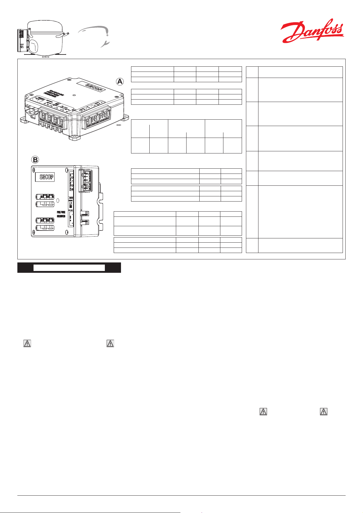
Compressor Module 101N0800, 12V DC
Compressor Module 101N0810, 24V DC
Application Module 101N0820, 12/24V DC
between -25º C and 40 º C is set with the software
and the temperature can also be seen by using the
interface. When using the “Auto” setting in the software it is not possible to obtain NTC failures, so it is
recommended to set the thermostat mode to “NTC”
when using a NTC.
Speed selection
Speed can be set through the Secop One Wire/LIN
Gateway communication interface (11). With factory
settings, the compressor will run with 2,500 rpm for
the fi rst 30 sec. and then step up to 4,000 rpm when
the thermostat is switched on.
Other fi xed compressor speeds and start speeds
in the range between 2,500 and 4,000 rpm can be
obtained when changing the speed settings in the
software.
A start delay in the range from 2-240 sec. (factory
setting 4 sec.) after thermostat cut-in can also be
chosen.
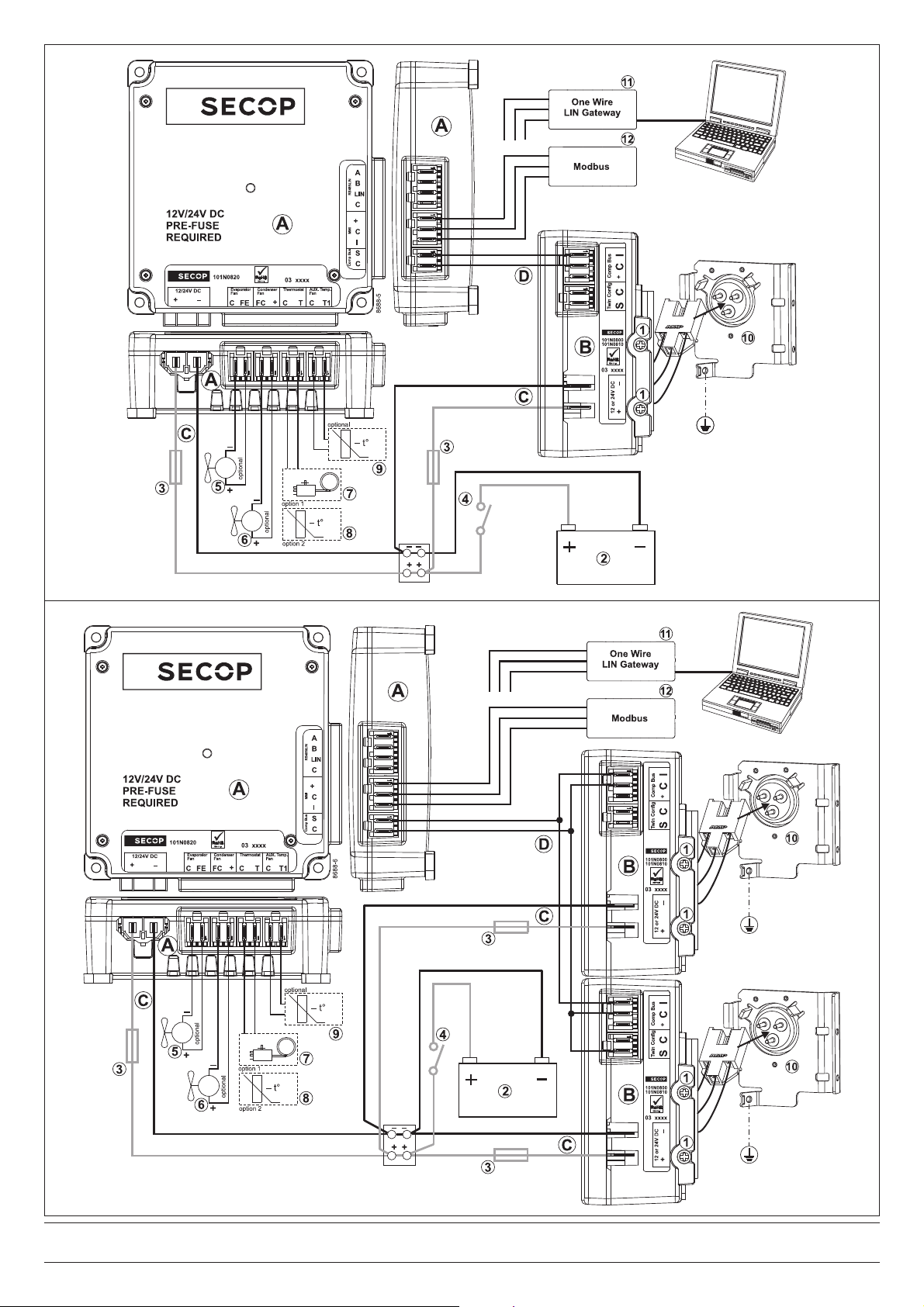
Fan (Fig. 6, page 2)
An evaporator fan (200W) (5) can be connected
between the terminals C and Fe and a condenser
fan (100W) (6) between + and Fc . Connect the plus
to + and the minus to Fc.
Connecting Fe with Fc
can destroy the unit.
If fans are used without adapting the software settings, the fans will run but no error signal will be sent
in case of fan failure.
It is also possible to set a start delay on the fans in
the range from 0-240 sec. Factory settings for the
evaporator fan is 6 sec. and for the condenser fan 0
sec. Fan speed can be adjusted through the interface
from 40-100%.
Error handling
If the compressor modules records an operational
error, the error can be read out in the software. Error
codes are defi ned as shown in Fig. 5.
The application module 101N0820 is a dual voltage device. This means that the same unit can be
used in both 12V and 24V power supply systems.
Maximum voltage is 17V for a 12V system and 31.5V
for a 24V power supply system. The compressor
module 101N0810 is a 24V single voltage device.
This means that the unit can only be used with 24V
DC power supply systems. The compressor module
101N0800 is a 12V single voltage device. This means
that the unit can only be used with 12V DC power
supply systems.
All modules must be protected
from direct splash water.
Max. ambient temperature is 55°C.
The modules have a built-in thermal protection which
is actuated and stops the compressor operation if
the electronic unit temperature becomes too high
(100°C/212°F on the PCB). The application module
can be connected to a PC through the Secop One
Wire/LIN Gateway communication interface (11) on
the MMI terminal (I/C/+). Communication gateway
modules incl. communication cables can be ordered
at Secop. The PC interface allows making different
settings and reading out several measurements by
using the software tool TOOL4COOL® supplied by
Secop (must be ordered separately). The application
module can also be connected to any modbuscompatible device (12) on the MMI terminal (I/C/+).
For detailed information please see the specfic
Operating Instructions literature.
Installation (Fig. 6, page 2)
Connect the terminal plug from the compressor
module (B) to the compressor(s) (10) and connect
the compressor module(s) to the application module
(A). The application module will automatically detect
whether a twin or a single confi guration is used. For
connecting the application module with the compressor module(s) cables supplied by Secop (D) can
be used (Fig. 4 ). Mount the electronic unit on the
compressor and fi x it with the two screws (1).
Power supply (Fig. 6, page 2)
All modules must always be connected directly to
the battery poles (2). Connect the plus to + and the
minus to -, otherwise the modules will not work.
The modules are protected against reverse battery
connection. For protection during installation, fuses
(3) should be mounted in the + cable as close as
possible to the modules. Each module must have
its own fuse. Recommended fuses and switches (4)
are shown in Fig. 3. The wire dimensions in Fig. 2
must be observed. Avoid extra junctions in the power
supply system to prevent voltage drop from affecting
the battery protection setting. Special supply cables
(C) can be ordered as accessories (Fig 4). When
using the compressor module 101N0800 (12V) the
application module must also be applied with 12V
DC. When using compressor module 101N0810
(24V) the application module must also be applied
with 24V DC.
Battery protection (Fig. 1)
The compressor stops and starts again according
to the chosen voltage limits measured on the + and
- terminals of the modules. The standard settings
for the power supply systems are shown in Fig. 1.
Other settings are set through the communication
interface.
Thermostat (Fig. 6, page 2)
The thermostat is connected between the terminals
C and T. Either a NTC (electrical thermostat) (8)
or a mechanical thermostat can be connected (7).
Another NTC (9) can also be connected between the
terminals C and T1 to obtain another temperature.
Three different thermostat modes can be chosen in
the software – “Auto” (both NTC and mechanical),
“NTC” or “Mechanical”. Standard setting is “Auto”. In
case of using a NTC the set point in the range
ENGLISH
Wire Dimensions 12V & 24V DC
Size Max. length*
12V operation
Max. length*
24V operation
Cross
section
AWG
[mm2]
[Gauge]
[m] [ft.] [m] [ft.]
2 x 4
2 x 6
2 x 10
11
9
7
0.75
1
2
2.46
3.28
6.60
1.5
2
4
4.92
6.60
13.12
*Length between battery and electronic unit
Fig. 2
Battery protection settings 12V DC (± 0.3 V DC, all values)
Voltage (0.1 steps) Min. value Default Max. value
Cut out VDC 9.6 10.4 17
Cut in diff. VDC 0.5 1.3 10
Battery protection settings 24V DC (± 0.3 V DC, all values)
Voltage (0.1 steps) Min. value Default Max. value
Cut out VDC 19 21.3 27
Cut in diff. VDC 0.5 1.3 10
Operational errors
Error
code
Error type
Can be read out in the software TOOL4COOL®
7
Communication failure
(In case of lost communication between the
compressor module(s) and the application
module, the compressor(s) and fans will be
switched off).
6
Thermostat failure
(If the NTC thermistor is short-circuit, has no
connection or is outside the operating range
(-60°C - 100°C), the compressor module(s) will
switch off and show a NTC failure).
5
Thermal cut-out of compressor module
(If the refrigeration system has been too hea vi ly
loaded, or if the ambient tem pe ra ture is high/
extremely low the compressor module(s) will
run too hot/too cold.
4
Minimum motor speed error
(If the refrigeration system is too heavily loaded, the motor cannot maintain minimum
speed at approximately 1,850 rpm).
3
Motor start error
(The rotor is blocked or the differential pressure
in the refrigeration system is too high).
2
Fan error / Fan missing
(The evaporator fan loads the electronic unit
with more than 18A for a 12V system and 9A for
a 24V system under start up. The current load
exceeds 16.5A for a 12V system or 8.25A for a
24V system under runing conditions).
(The condenser fan loads the electronic unit
with more than 9A for a 12V system and 9.5A for
a 24V system under start up. The current load
exceeds 8.5A for a 12V system or 4.25A for a
24V system under runing conditions).
1
Battery protection cut-out
(The voltage is outside the cut-out setting,
compressor(s) and fans will stop).
Fig. 1
Available cord sets Packages 1500 mm
3000 mm
Single compressor
communication cable assembly
I - Pack 105N9553 105N9554
Twin compressor
communication cable assembly
I - Pack 105N9555 105N9556
Available cord sets Packages 900 mm
2000 mm
12V DC line cord I - Pack 105N9560 105N9559
24V DC line cord I - Pack 105N9543 105N9541
Fig. 4 Fig. 5
For wiring schemes see page 2.
Compressor Modules
101N0800 & 101N0810
Application Module 101N0820
Recommended fuses and switches
Fuses 12V DC 24V DC
Application module 30A 15A
Compressor module 60A 30A
Main switches 12V DC 24V DC
Single compressor confi guration 75A 38A
Twin compressor confi guration 150A 75A
Fig. 3
Flexible control settings
TOOL
COOL
4
Page 2
2/2 Designed and manufactured by Secop for DANFOSS - DEHC.EI.100.V3.02 / 520N0775 August 2011
Danfoss can accept no responsibility for possible errors in catalogues, brochures and other printed material. Danfoss reserves the right to alter its products without notice. This also applies to products
already on order provided that such alterations can be made without subsequential changes being necessary in specifi cations already agreed.
All trademarks in this material are property of the respective companies. Danfoss and the Danfoss logotype are trademarks of Danfoss A/S. All rights reserved.
Fig. 6 - single compressor
Fig. 6 - twin compressor confi guration
 Loading...