

Page 1
August 2011 compressors.danfoss.com - DEHC.EI.100.G6.02 / 520N0232 1/2
Instructions
Electronic Unit for BD35/BD50F Compressors,
101N0500, 12/24V DC & 100-240V AC 50/60Hz
The electronic unit is a multi voltage device. It can
be used in both 12V/24V DC and 100-240V AC
50/60Hz power supply systems. Max. voltage is
17V DC for a 12V DC system and 31.5V DC for
a 24V DC power supply system. Max. voltage is
265V AC and min. 85V AC for an AC power supply
system. Max. ambient temperature is 55°C. The
electronic unit has a built-in thermal protection
which is actuated and stops the compressor operation if the electronic unit temperature becomes
too high (100°C / 212°F on the PCB). Power
consumption is limited to 100W. See datasheet
BD50F for details.
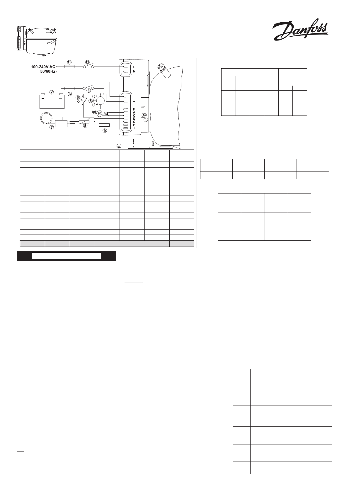
Installation (Fig. 1)
Connect the terminal plug from the electronic unit
to the compressor terminal. Mount the electronic
unit on the compressor by snapping the cover
over the screw head (1).
Power supply (Fig. 1)
DC: The electronic unit must always be connected
directly to the battery poles (2). Connect the plus
to + and the minus to -, otherwise the electronic
unit will not work. The electronic unit is protected
against reverse battery connection.
For protection of the installation, a fuse (3) must
be mounted in the + cable as close to the battery
as possible. It is recommended to use 15A fuses
for 12V and 7.5A fuses for 24V circuits. If a main
switch (4) is used, it should be rated to a current
of min. 20A. The wire dimensions in Fig. 2 must
be observed. Avoid extra junctions in the power
supply system to prevent voltage drop from affecting the battery protection setting.
AC: The wires must be connected to the terminal
marked L and N on the electronic unit. Nominal
voltages from 100 to 240 VAC 50/60Hz. Upper
safety cut-out limit = 270V AC and lower limit 80V
AC. A 4A fuse (11) must be mounted in the live
(L) cable to protect the installation.
If a main switch (12) is used, it should be rated to
a current of min. 6A. The wire dimensions must
be min. 0.75 mm2 or AWG 18.
NB: Earth connection can be used if required.
General: Both the AC and the DC power supply
can be connected to the electronic unit at the
same time. In this case, AC will be preferred power
supply source. If the AC power supply is disconnected or drop below 85V AC on a 12V DC supply
system, a time delay of 1 min. will be activated
before the compressor continues on DC power
supply. If AC power supply is re-established there
will be no delay in compressor operation.
Battery protection (Fig. 1)
The compressor stops and restarts again according to the designated voltage limits measured on
the + and - terminals of the electronic unit.
The standard settings for 12V and 24V power
supply systems appear from Fig. 3.
Other settings are optional if a connection which
includes a resistor (9) is established between
terminals C and P. See manual.
Thermostat (Fig. 1)
The thermostat (7) is connected between the terminals C and T. Without any resistor in the control
circuit, the compressor will run with a fi xed speed
of 2,000 rpm when the thermostat is switched on.
Other fi xed compressor speeds in the range between 2,000 and 3,500 rpm can be obtained when
a resistor (8) is installed to adjust the current (mA)
of the control circuit. Resistor values for various
motor speeds appear from Fig. 5.
Fan (optional, Fig. 1)
A fan (5) can be connected between the terminals
+ and F. Connect the plus to + and the minus to
F. Since the output voltage between the terminals
+ and F is always regulated to 12V,
a 12V fan must be used for both 12V and 24V
power supply systems.
Fig. 1
Optional battery
protection settings DC
Fig. 4
ENGLISH
The fan output can supply a continuous current
of 0.5A
avg
. A higher current draw is allowed for 2
seconds during start.
Lamp (optional, Fig. 1)
A 12V DC 5 Watt lamp (10) can be connected
between the terminals A and C. The output voltage between the terminals A and C is always
regulated to 12V DC. A 12V DC lamp must be
used for both 12V and 24V power supply systems.The lamp output can supply a continuous
current of 0.5A
avg
.
LED (optional, Fig. 1)
A 10mA light emitting diode (LED) (6) can be
connected between the terminals + and D. If the
electronic unit records an operational error, the
diode will fl ash a number of times. The number of
fl ashes depends on what kind of operational error
was recorded. Each fl ash will last ¼ second. After
the actual number of fl ashes there will be a delay
with no fl ashes, so that the sequence for each error recording is repeated every 4 seconds.
24V max.
Voltage
31.5
31.5
31.5
31.5
31.5
31.5
31.5
31.5
31.5
31.5
31.5
31.5
31.5
31.5
31.5
24V cut-in
V
22.7
22.9
23.2
23.4
23.7
23.9
24.2
24.5
24.7
25.0
25.2
25.5
25.7
26.0
24V cut-out
V
21.3
21.5
21.8
22.0
22.3
22.5
22.8
23.0
23.3
23.6
23.8
24.1
24.3
24.6
12V max.
Voltage
17.0
17.0
17.0
17.0
17.0
17.0
17.0
17.0
17.0
17.0
17.0
17.0
17.0
17.0
12V cut-in
V
10.9
11.0
11.1
11.3
11.4
11.5
11.7
11.8
11.9
12.0
12.2
12.3
12.4
12.5
10.9
12V cut-out
V
9.6
9.7
9.9
10.0
10.1
10.2
10.4
10.5
10.6
10.8
10.9
11.0
11.1
11.3
9.6
Resistor
(9) kΩ
0
1.6
2.4
3.6
4.7
6.2
8.2
11
14
18
24
33
47
82
220
Number
of
fl ashes
Error type
Thermal cut-out of electronic unit
(If the refrigeration system has been too hea vi ly
loaded or if the ambient temperature is high, the
electronic unit will run too hot).
5
Minimum motor speed error
(If the refrigeration system is too heavily loaded,
the motor cannot maintain minimum speed
1,850 rpm).
4
Motor start error3
(The rotor is blocked or the differential pressure
in the refrigeration system is too high (>5 bar)).
Fan over-current cut-out2
(The fan loads the electronic unit with more
than 1A
peak
).
1
Battery protection cut-out
(The voltage is outside the cut-out setting).
Fig. 3
24V cut-out
V
22.8
12V cut-in
V
11.7
24V cut - in
V
24.2
12V cut-out
V
10.4
Standard battery protection settings DC
Compressor speed
Electronic
unit
101N0500
Motor
speed
rpm
2,000
2,500
3,000
3,500
Resistor
(8) Ω
(calculated)
0
277
692
1523
Contr.circ.
current
mA
5
4
3
2
Fig. 5
Fig. 2
Wire dimensions DC
*Length between battery and electronic unit
Max length*
24V DC
operation
ft. m
16 5
26 8
39 12
66 20
Size
AWG Cross
section
Gauge mm
2
12 2.5
12 4
10 6
8 10
Max length*
12V DC
operation
ft. m
8 2.5
13 4
20 6
33 10
Wire dimensions AC
Cross section min. 0.75 mm2 or AWG 18
Page 2
2/2 Designed and manufactured by Secop for DANFOSS - DEHC.EI.100.G6.02 / 520N0232 August 2011
Danfoss can accept no responsibility for possible errors in catalogues, brochures and other printed material. Danfoss reserves the right to alter its products without notice. This also applies to products
already on order provided that such alterations can be made without subsequential changes being necessary in specifi cations already agreed.
All trademarks in this material are property of the respective companies. Danfoss and the Danfoss logotype are trademarks of Danfoss A/S. All rights reserved.
Instructions
Electronic Units for BD Compressors
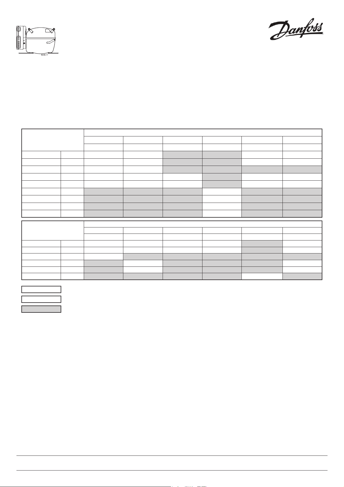
VDE/UL Approvals for BD Compressors
Approved Compressor - Electronic Unit Combinations
Compressors Electronic Units
Standard EMI High start High speed AEO AEO EMI
101N0210 101N0220 101N0230 101N0290 101N0300 101N0320
BD35F mm 101Z0200
UL UL UL
BD35F inch 101Z0204
UL UL UL
BD35K (R600a) 101Z0211
BD50F mm 101Z1220
UL UL UL UL
BD50F inch 101Z0203
UL UL UL UL
BD80F mm 101Z0280
BD250GH 101Z0400
BD250GH Twin 101Z0500
BD100CN (R290) 101Z0401
Compressors Electronic Units
Solar AC/DC converter Automotive Automotive Telecommunication Extended EMI
101N0400 101N0500 101N0600 101N0630 101N0730 101N0900
BD35F mm 101Z0200
UL VDE/UL
BD35F inch 101Z0204
UL VDE/UL
BD35K (R600a) 101Z0211
BD50F mm 101Z1220
VDE/UL
BD50F inch 101Z0203
VDE/UL
BD250GH (48V) 101Z0402
UL
VDE/UL
= Combination possible, VDE or UL approval
= Combination possible, but no approval
= Combination not possible
 Loading...