

Page 1
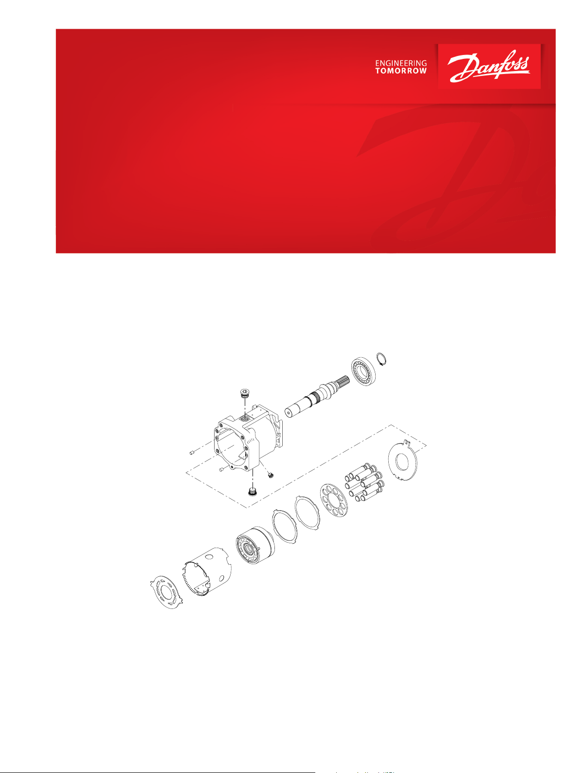
Parts Manual
Series 90 100cc
Axial Piston Motor
www.danfoss.com
Page 2

Parts Manual
Series 90 Motors, 100cc
Revision history Table of revisions
Date Changed Rev
January 2020 Removed obsolete option 0204
September 2018 Corrected o-ring quantities in the seal kit 0203
January 2018 Updated to Engineering Tomorrow 0202
2 | © Danfoss | January 2020 AX00000094en-000204
Page 3

Parts Manual
Series 90 Motors, 100cc
Contents
General information
Service Parts Identification............................................................................................................................................................4
Nameplate...........................................................................................................................................................................................4
Date code............................................................................................................................................................................................ 5
About service bulletins...................................................................................................................................................................5
Procedure to identify a part..........................................................................................................................................................5
Regional part numbers............................................................................................................................................................. 5
Example of a part identification (S90 100cc motor)....................................................................................................... 5
Adobe Acrobat 2-page viewing..................................................................................................................................................6
Order code.......................................................................................................................................................................................... 7
Common parts and special hardware
Common parts and special hardware CAA, CBA...................................................................................................................8
Special hardware CBC, CBE.........................................................................................................................................................12
Special hardware EAA, EBA, EFT............................................................................................................................................... 14
Special hardware EBB-EEH..........................................................................................................................................................16
Special hardware EFA-EFM.........................................................................................................................................................20
Special hardware EGL-JAB.......................................................................................................................................................... 24
Special hardware JAE-JCB...........................................................................................................................................................28
Special hardware LAB-NNN........................................................................................................................................................32
Special hardware PAA, PAB........................................................................................................................................................34
End cap
End cap 1-8, D, E............................................................................................................................................................................. 36
End cap F-Q......................................................................................................................................................................................40
End cap T, U......................................................................................................................................................................................44
End cap V, W, X................................................................................................................................................................................46
Loop flushing
Loop flushing B-W......................................................................................................................................................................... 48
Charge pressure setting
Charge pressure setting 00-N6................................................................................................................................................. 50
Shaft
Shaft C6-TJ........................................................................................................................................................................................54
Overhaul seal kit
Seal kit................................................................................................................................................................................................56
Service bulletin
SB-1988-018.....................................................................................................................................................................................57
SB-1988-023.....................................................................................................................................................................................59
SB-1989-020.....................................................................................................................................................................................61
SB-1998-007.....................................................................................................................................................................................64
SB-1999-036.....................................................................................................................................................................................66
SB-2000-047.....................................................................................................................................................................................68
SB-2001-011.....................................................................................................................................................................................69
SB-2002-048.....................................................................................................................................................................................70
SB-2003-010.....................................................................................................................................................................................71
©
Danfoss | January 2020 AX00000094en-000204 | 3
Page 4
MADE IN P. R. C.
Serial No. Fabr- Nr
C-01-16-23456
Model Code Typ
Model No.
90M100 NC 0 N 8 N 0
S1 W 00 EAA 00 00 N6
83023054
Ident-Nr
Parts Manual
Series 90 Motors, 100cc
General information
Service Parts Identification
Nameplate
The following information and procedure is used to identify the module group, item number,
manufacture date, part number, and part name of the parts included in the .
The parts listed include all parts which may be used when performing either “Minor Repairs”, “Major
Repairs” or “Conversions” on the .
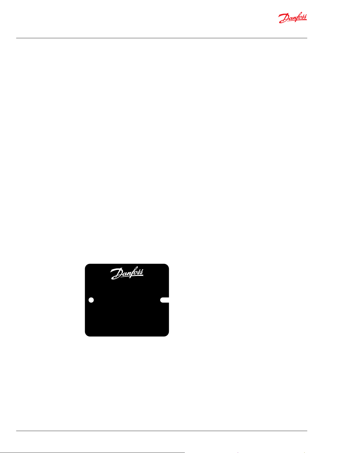
Each unit will have a nameplate affixed to the housing. The nameplate will include the following
information:
Model Code
The Danfoss model code completely defines the specific unit and must be used when ordering parts to
service this product.
Model Number
The Danfoss model number is used by the factory in manufacturing. On repeat orders, a complete unit
can be ordered by the model number.
Serial Number
The Danfoss serial number is used to identify the manufacture date and the unit sequence in the build.
The serial number is also used to identify the units warranty time period.
The letter code indicates the location of original manufacture (assembly).
The first number (2 digits) indicates the year of manufacture. The second number (2 digits) indicates the
calendar week of manufacture.
The third number (5 digits) is a sequential number used to identify a specific unit.
4 | © Danfoss | January 2020 AX00000094en-000204
Page 5
Parts Manual
Series 90 Motors, 100cc
General information
Date code
About service bulletins
The date code is defined as the year and week of manufacture. The same item number may list more than
one part number. This indicates that there is more than one configuration for that item number. You will
see that there are different date codes for the different part numbers. Find the date code of your unit
from the nameplate to determine which service part number you need to order.
Example: The service part desired is item G30
Order Code Item Date Begin Date End Part Number Part Name Qty. per
80 G30 89-17 8000243 End cap gasket 1
G30 89-16 8000151 End cap gasket
(SB-1995-006)
Model/Kit
1
All units using this order code with a date code prior to 89-17 must use part number “8000151.” All units
with a date code of 89-17 and newer must use part number “8000243.”
A Service Bulletin Number (SB-_ _ _ _ - _ _ _) may follow the “Part Name” of the part you desire. You must
read that Service Bulletin prior to ordering that part. The information contained in these Service Bulletins,
as of the print date of this bulletin, are included at the end of this manual. Service Bulletins contain more
detailed information such as interchangeability, what additional parts are involved, etc. It is suggested
that you add additional Service Bulletins to this manual as you receive them.
Procedure to identify a part
The modular design of this product results in a simplified service parts list and part number identification
procedure.
The same item numbers are used for same part names on all units within a product type. A part number
that has another number following it in parentheses is done to make this a world wide manual.
Regional part numbers
Some part numbers are region specific and should be ordered accordingly.
As an example, the part number (example: 314583 (9008000-0118) will be used. The first number is sold
in Germany. The number in parentheses is sold in the United States. Customers would order
9008000-0118 if ordering the part in the United States.
Example of a part identification (S90 100cc motor)
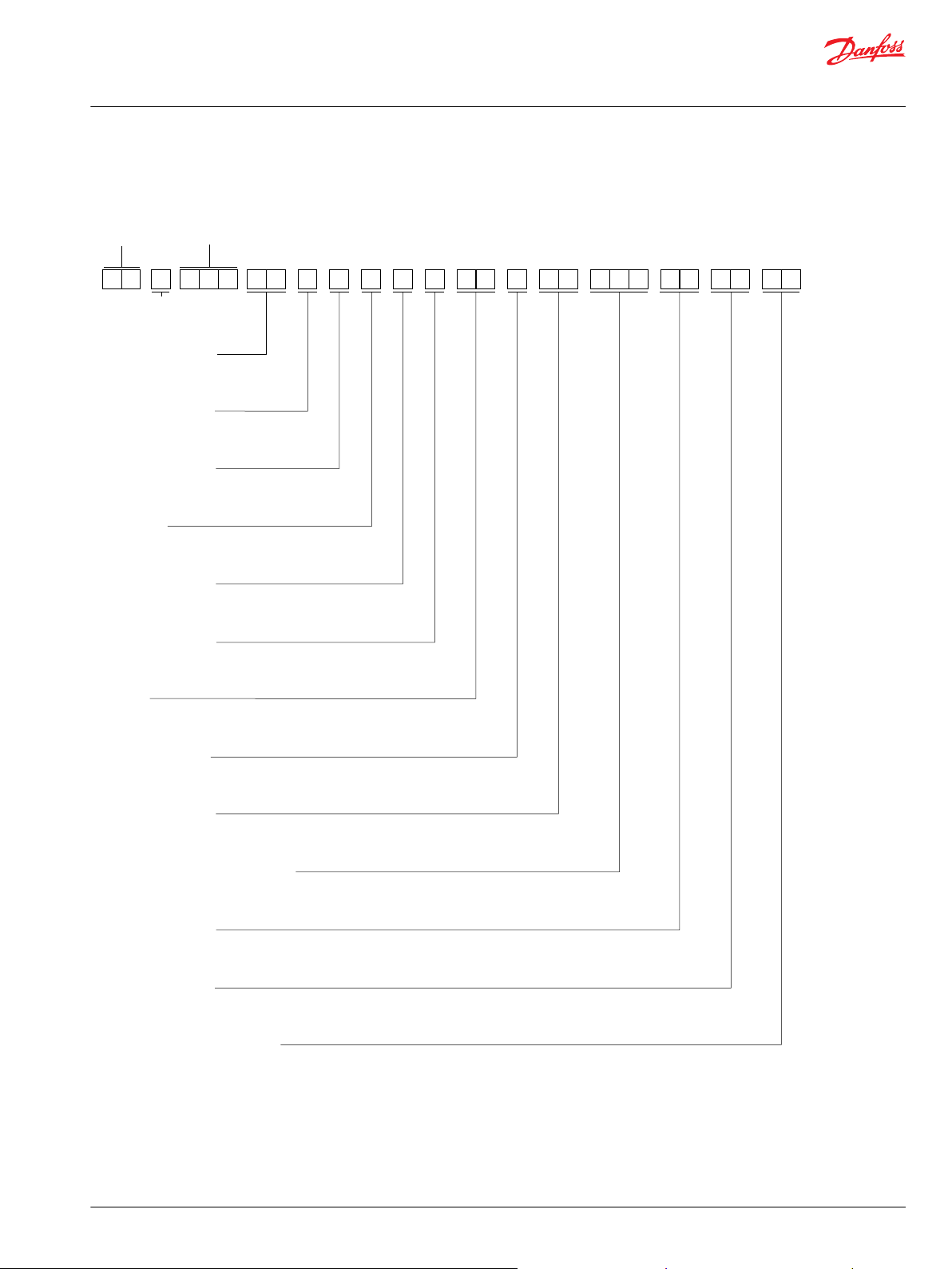
The nameplate on a Series 90 motor has an Order Code of 90M100 NC 0 N 8 N 0 S1 W 00 EAA 00 00 N6.
Use the following procedures to determine the part number of the drive shaft used on this motor.
1. Referring to the shaft module in the Order code on page 7, the shaft option for this motor is
identified by the code “S1”. (90M100 NC 0 N 8 N 0
S1W 00 EAA 00 00 N6)
2. Referring to the Service Parts List, find the shaft group. Next find the order code that relates to this
unit,which is “S1”. The shaft is found to be item L100 and part number 11012429.
©
Danfoss | January 2020 AX00000094en-000204 | 5
Page 6
Parts Manual
Series 90 Motors, 100cc
General information
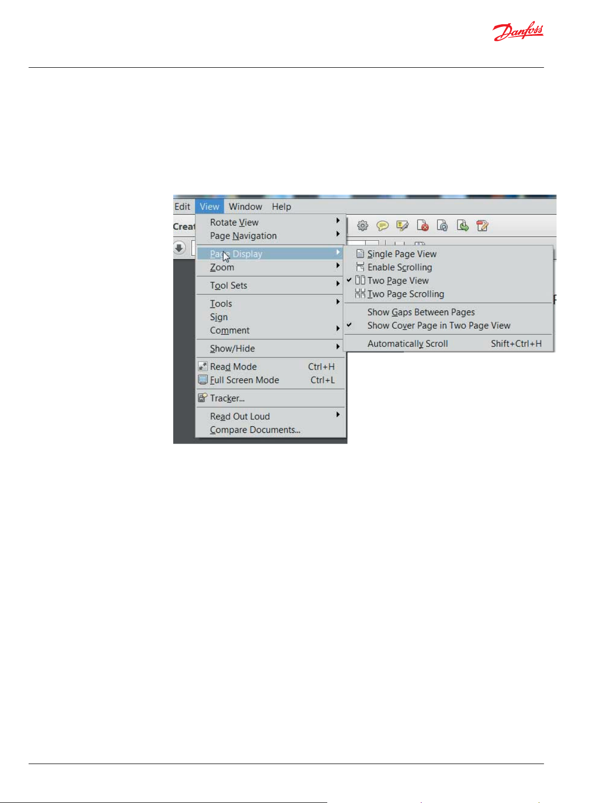
Adobe Acrobat 2-page viewing
While viewing manual in Adobe Acrobat, the following settings need to be applied to ensure proper
page display.
1. Select “View” → “Page Display” → “Two Page View”
2. Select “View” → “Page Display” → “Show Cover Page in Two Page View”
6 | © Danfoss | January 2020 AX00000094en-000204
Page 7
9
0
M
0
1
0
N
C
0
N
8
S 1
0
N
0 0
W
2 4
0
N N
N
0 0
0
Series
Displacement
Not applicable
Not applicable
End cap
Not applicable
Not applicable
Not applicable
Shaft
Loop flushing
Not applicable
G L H W K
Special hardware features
Not applicable
Not applicable
Charge pressure setting
Type
Parts Manual
Series 90 Motors, 100cc
General information
Order code
©
Danfoss | January 2020 AX00000094en-000204 | 7
Page 8
B83
L20
L10
B10
B50
*G30
B50
G96
G90
B81
L50
L40
*L25
G90
L70
L60
D50
C50
C80
C20
QC04
C30
C40
C45
C05
B80
Parts Manual
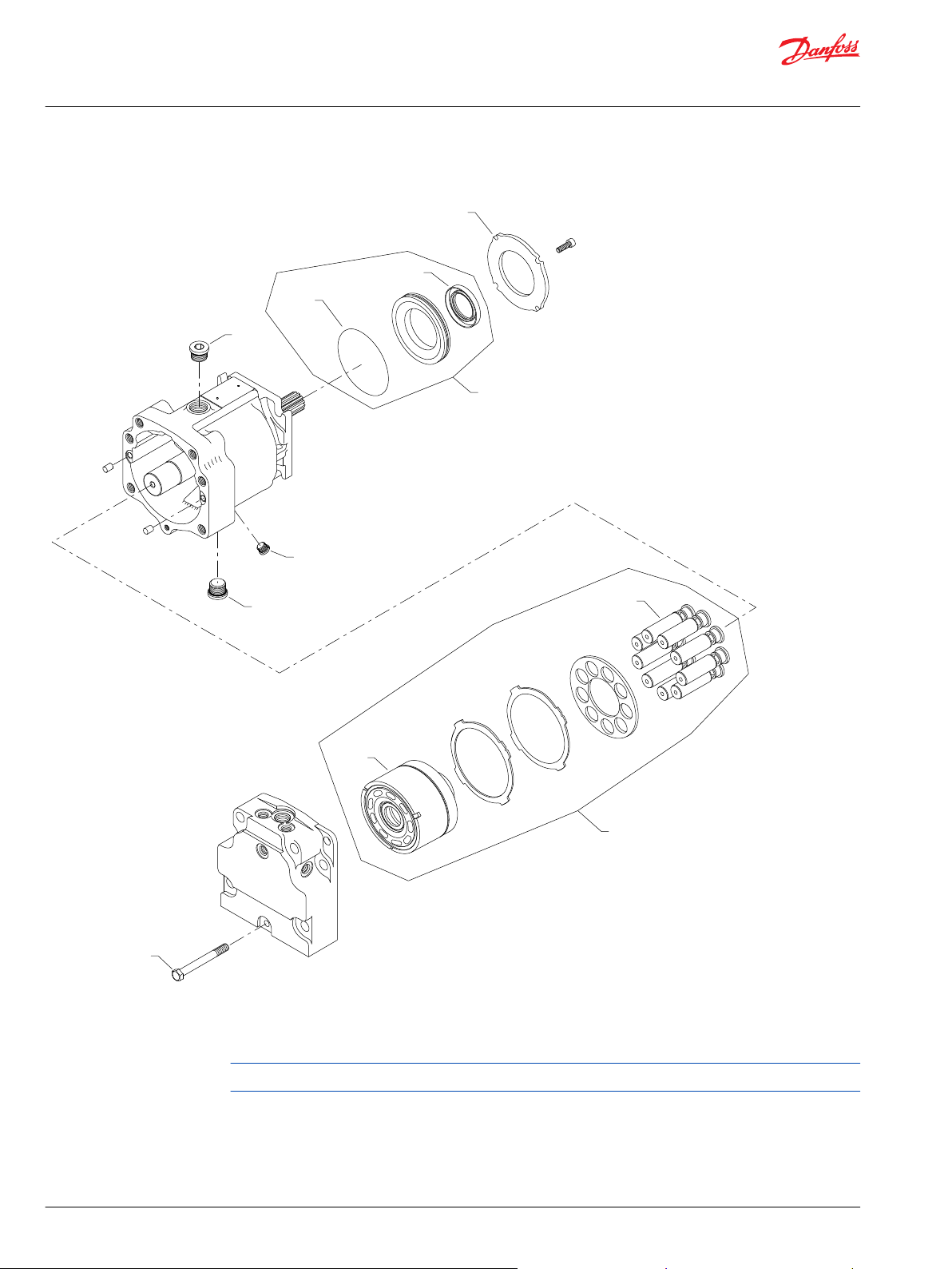
Series 90 Motors, 100cc
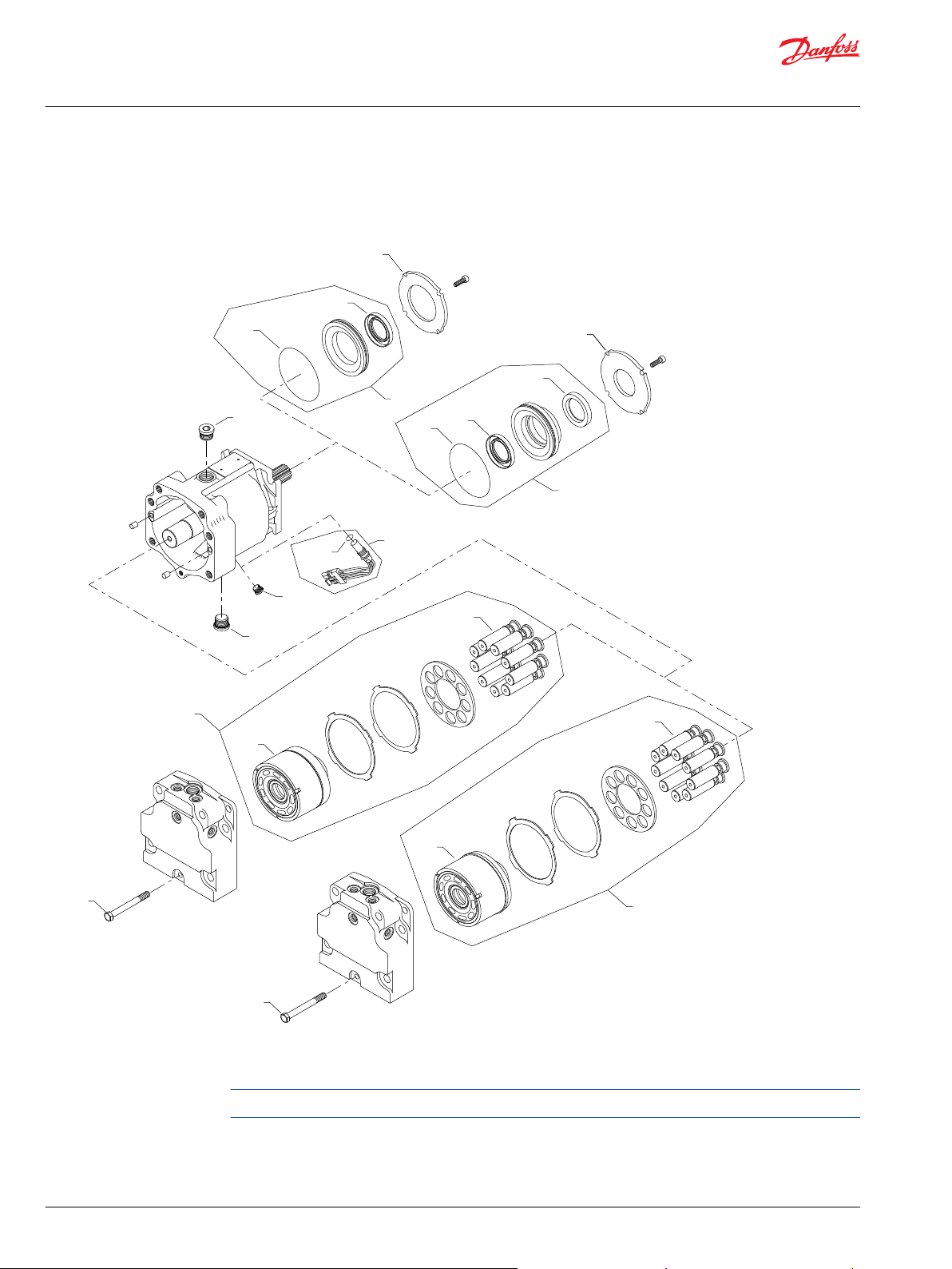
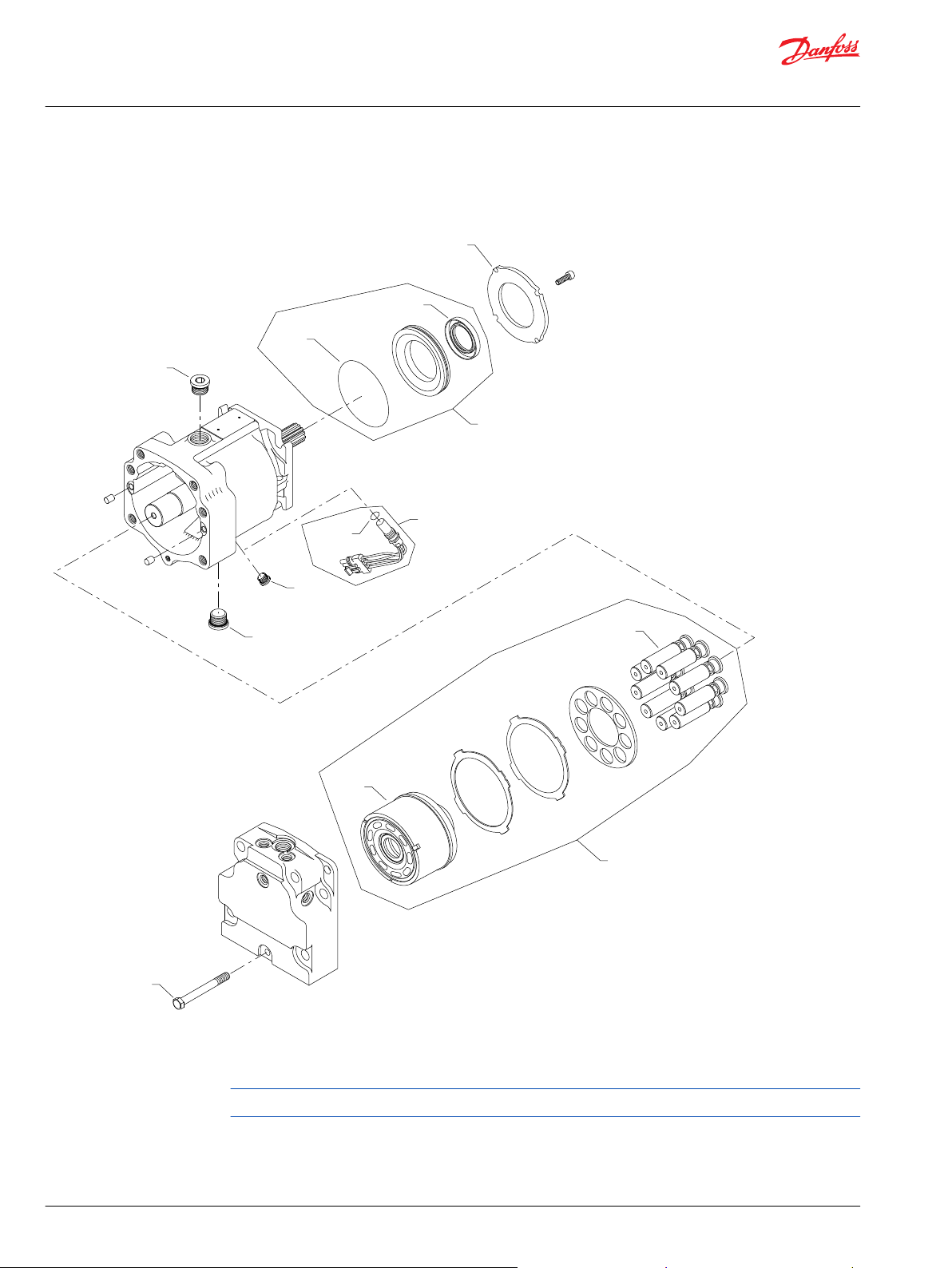
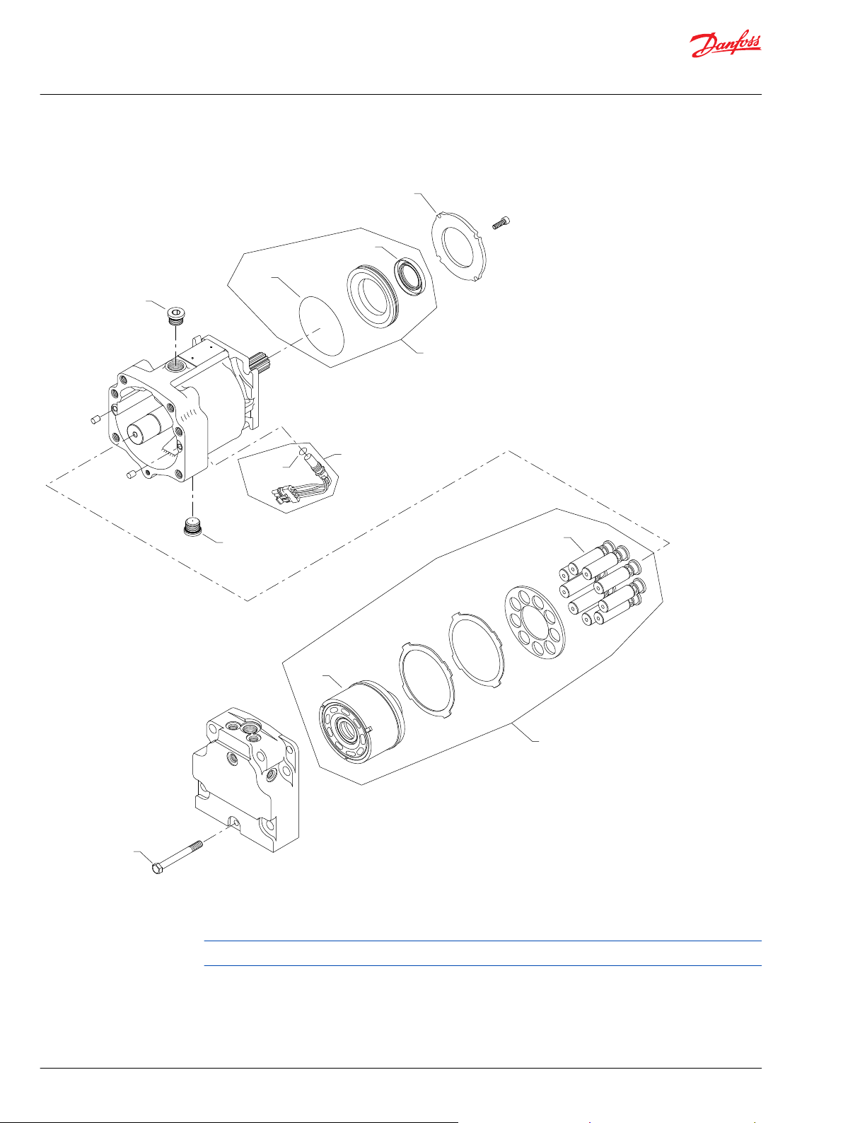
Common parts and special hardware
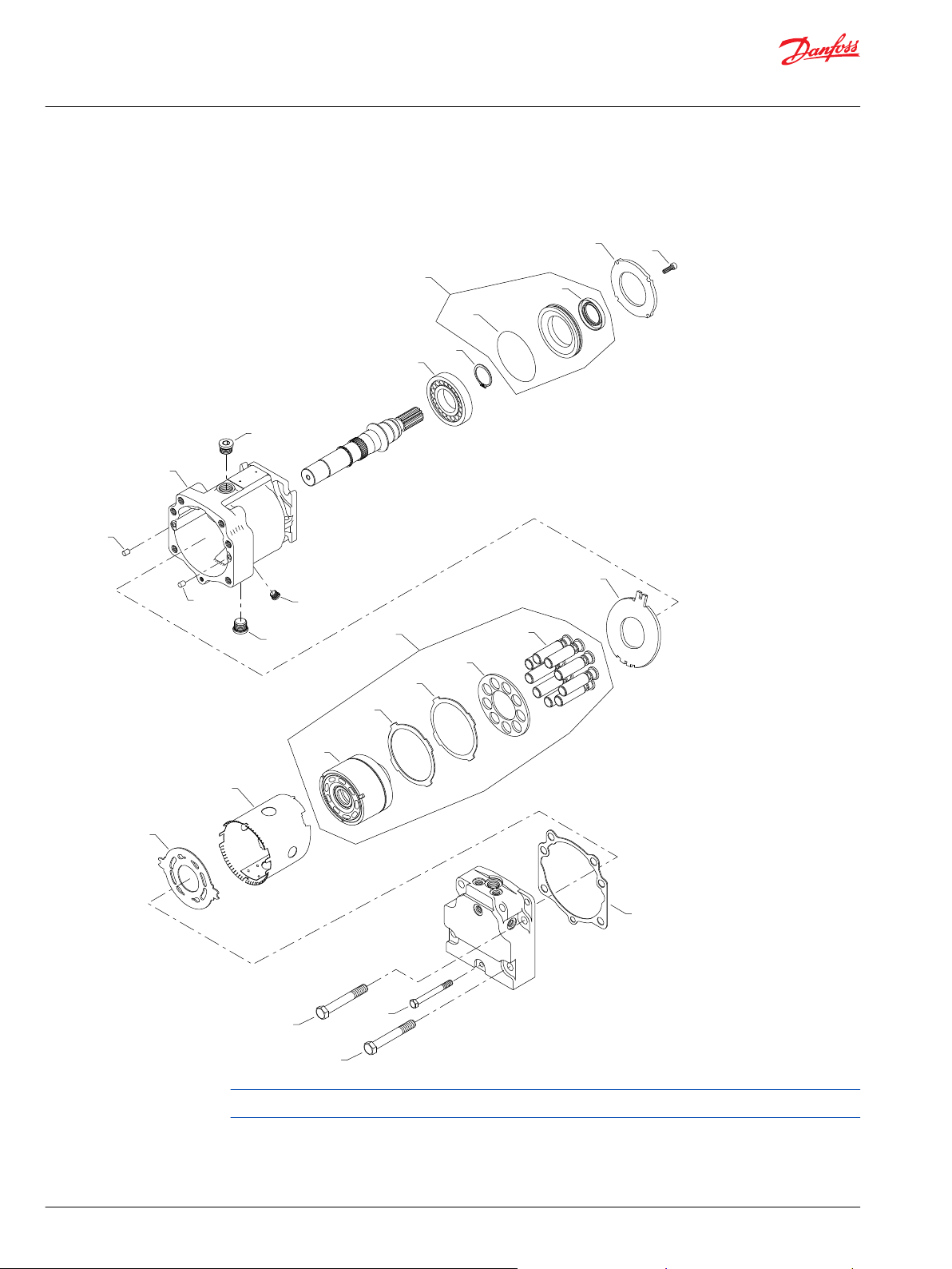
S90 100cc motor special hardware CAA, CBA
Parts configuration
Generic end cap used to show part location only
* Included in overhaul seal kit Q210
8 | © Danfoss | January 2020 AX00000094en-000204
Page 9
Parts Manual
Series 90 Motors, 100cc
Common parts and special hardware
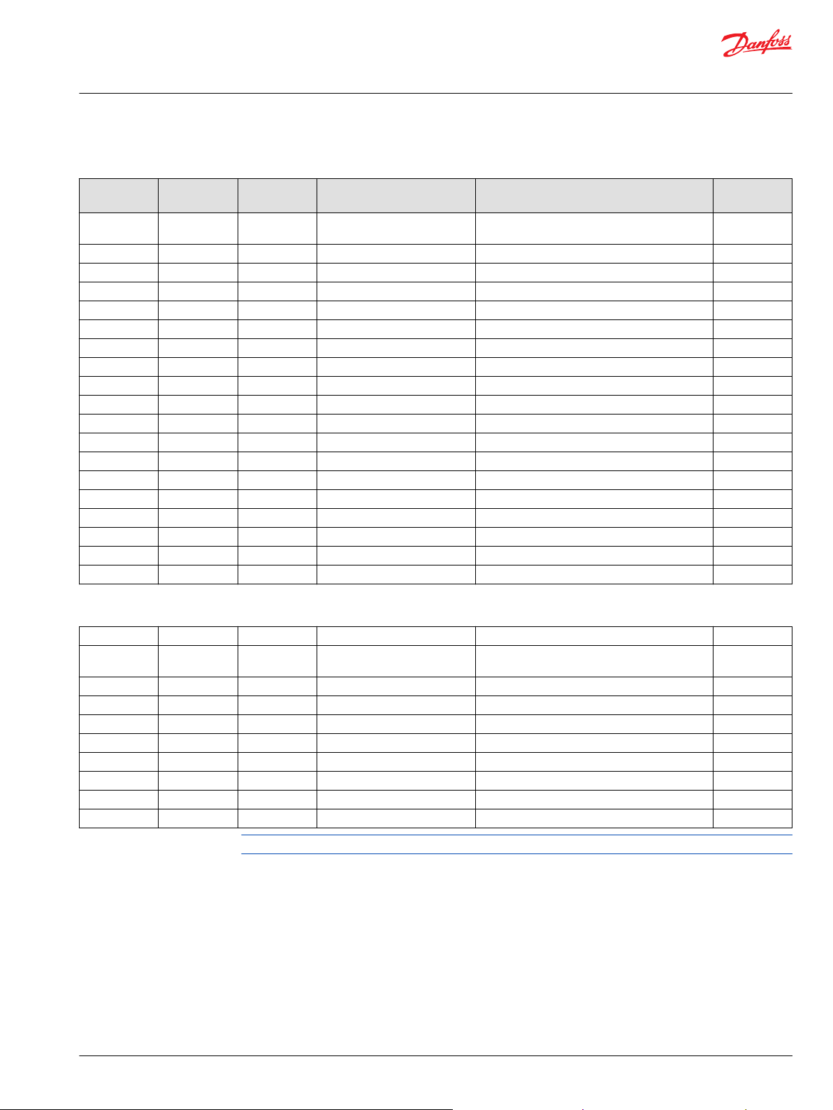
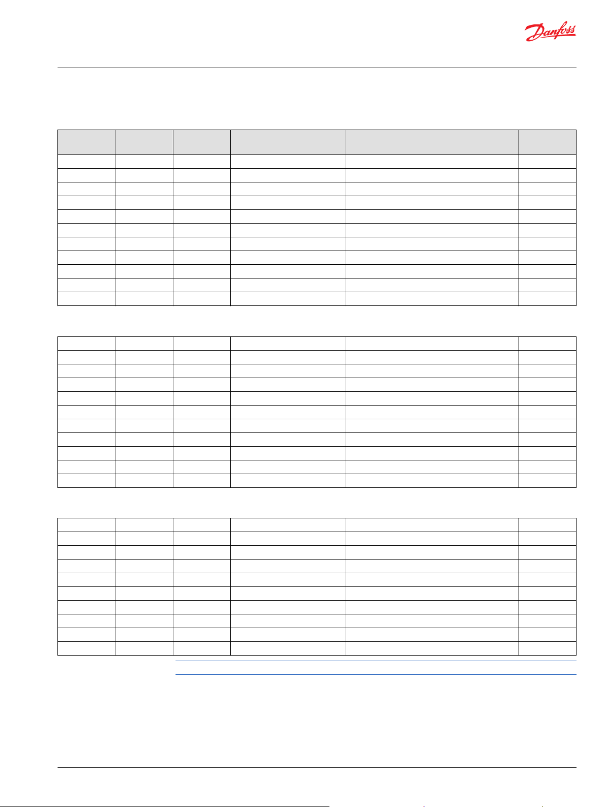
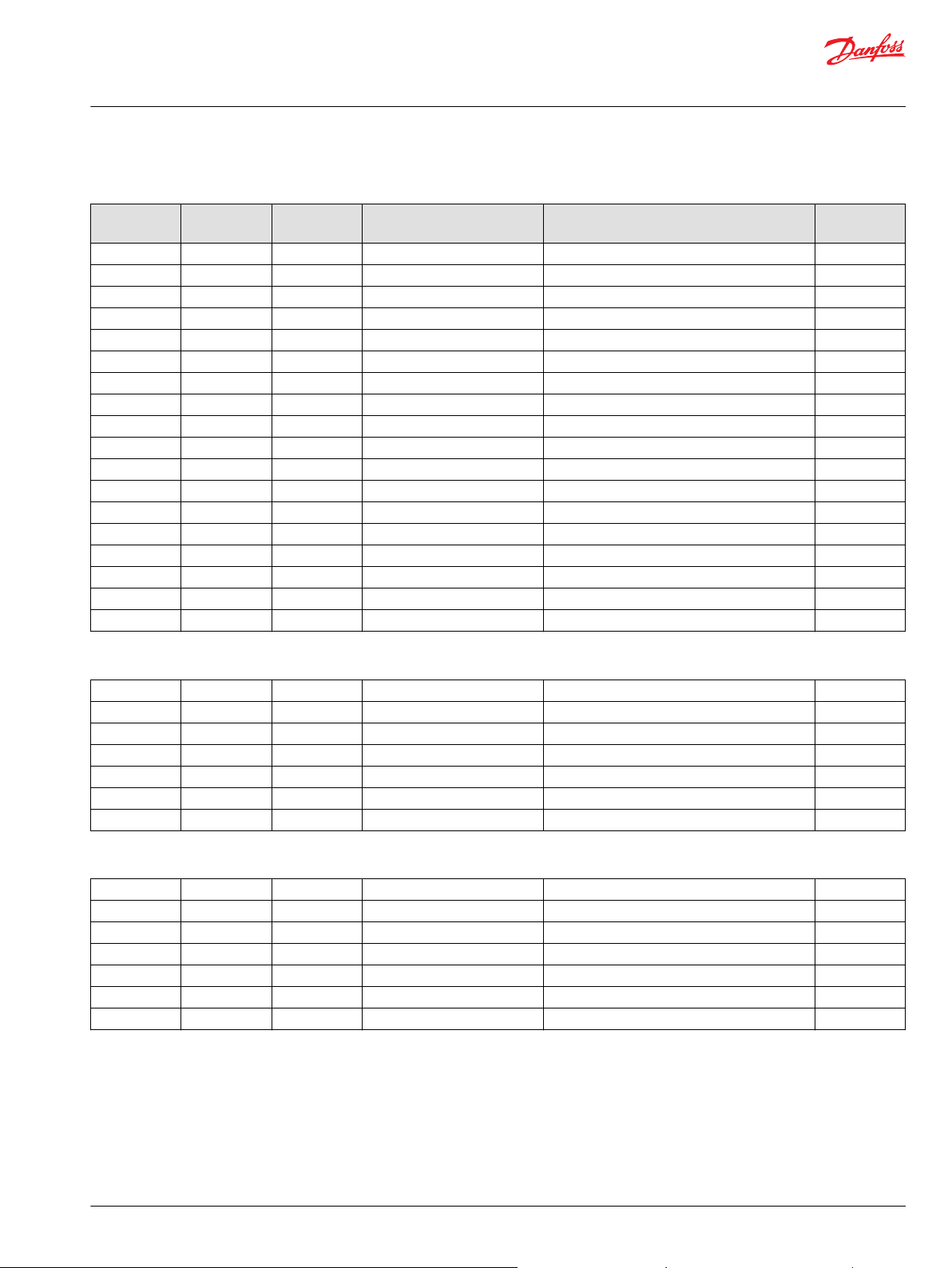
Common parts
Item Date Begin Date End Part Number Part Name Quantity per
B10 88-23 8200561 Housing (SB-1988-018 on page 57, SB-1999-036
on page 66, and SB-2003-010 on page 71)
B50 88-23 9004800-3708 Pin (SB-1988-018 on page 57) 2
B50 87-07 88-22 9004800-3116 Pin 2
B80 87-07 664524 (9005110-9000) Plug assembly 1
B81 87-07 664524 (9005110-9000) Plug assembly 1
C30 87-07 11067351 Slipper guide 1
C40 87-07 11057798 Slipper guide retainer 1
C45 87-07 11063829 Slipper guide retainer spacer 1
C50 87-07 8200237 Hold down tube 1
C80 88-23 324137 Valve plate (SB-2002-048 on page 70) 1
C80 87-07 88-22 8200103 Valve plate (SB-1988-018 on page 57) 1
D50 88-23 11136453 Thrust plate (SB-1988-018 on page 57) 1
G30 87-07 8200511 End cap gasket (SB-2001-011 on page 69) 1
G90 04-15 674424 (9007210-1617) Screw 6
G90 87-07 04-14 674424(9007210-1617) Screw (SB-2003-010 on page 71) 4
G95 87-07 04-14 675900 (9007210-1609) Screw (SB-2003-010 on page 71) 2
L10 87-07 5000506 Roller bearing 1
L20 87-07 9006300-0175 Retaining ring 1
L70 87-07 041160 (9007314-0605) Screw 4
Model/Kit
1
Order code: CAA
C05 94-14 519257 (11012434) Cylinder block assembly without speed ring 1
C20 94-14 8200031 Piston assembly, hollow (SB-1988-023 on page
59)
B83 94-14 140644 Plug assembly 1
G96 94-14 307686 (9007210-1017) Screw, M10 x 80 1
L25 94-14 521722 Seal carrier assembly 1
L40 94-14 519021 Lip seal 1
L50 94-14 327627 (9004104-1540) O-ring 1
L60 94-14 516768 Retainer plate 1
QC04 94-14 8510369 Cylinder block kit, without speed ring 1
Q210 94-14 11134055 Overhaul seal kit, standard 1
Parts continue to the next 2 pages.
9
©
Danfoss | January 2020 AX00000094en-000204 | 9
Page 10
B83
L20
L10
B10
B50
*G30
B50
G96
G90
B81
L50
L40
*L25
G90
L70
L60
D50
C50
C80
C20
QC04
C30
C40
C45
C05
B80
Parts Manual
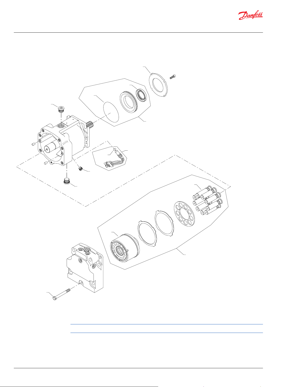
Series 90 Motors, 100cc
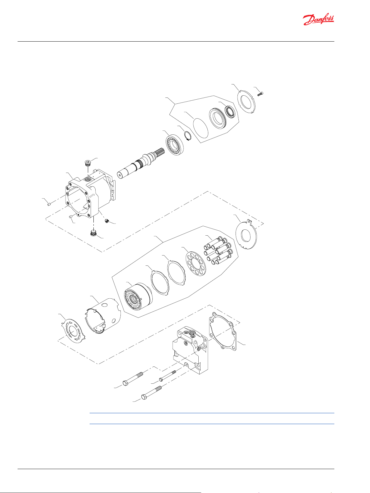
Common parts and special hardware
Parts configuration
Generic end cap used to show part location only
* Included in overhaul seal kit Q210
10 | © Danfoss | January 2020 AX00000094en-000204
Page 11

Parts Manual
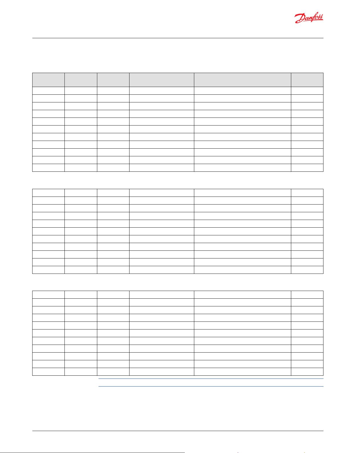
Series 90 Motors, 100cc
Common parts and special hardware
Order code: CBA
Item Date Begin Date End Part Number Part Name Quantity per
C05 94-14 519257 (11012434) Cylinder block assembly without speed ring 1
C20 94-14 508080 Piston assembly 9
B83 94-14 140644 Plug assembly 1
G96 94-14 307686 (9007210-1017) Screw, M10 x 80 1
L25 94-14 521722 Seal carrier assembly 1
L40 94-14 519021 Lip seal 1
L50 94-14 327627 (9004104-1540) O-ring 1
L60 94-14 516768 Retainer plate 1
QC04 94-14 11133858 Cylinder block kit, without speed ring 1
Q210 94-14 11134055 Overhaul seal kit, standard 1
Model/Kit
©
Danfoss | January 2020 AX00000094en-000204 | 11
Page 12
B83
L60
C20
QC04
C05
L50
L40
*L25
B81
B80
*L25
L44
L42
L50
L60
C06
C20
QC04
G96
G96
B83
*QB83
Parts Manual
Series 90 Motors, 100cc
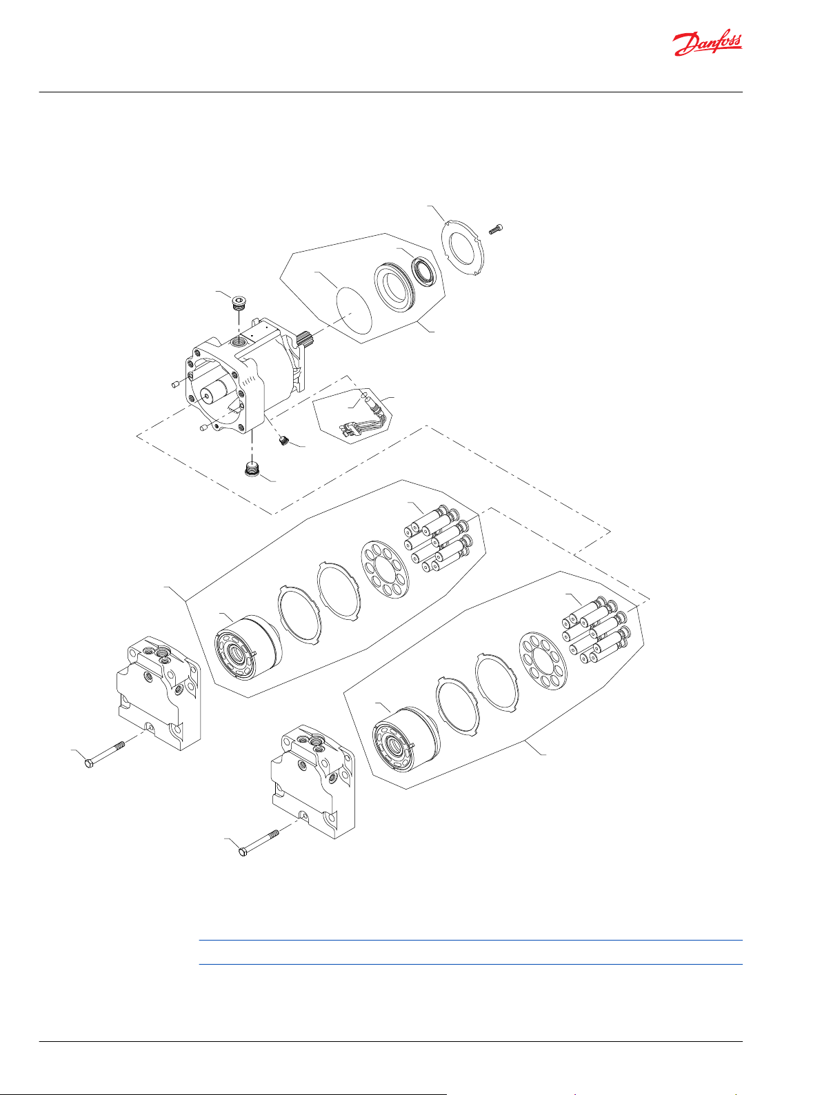
Common parts and special hardware
S90 100cc motor special hardware CBC, CBE
Parts configuration
Generic end cap used to show part location only
* Included in overhaul seal kit Q210
12 | © Danfoss | January 2020 AX00000094en-000204
Page 13
Parts Manual
Series 90 Motors, 100cc
Common parts and special hardware
Order code: CBC
Item Date Begin Date End Part Number Part Name Quantity per
C05 94-14 519257 (11012434) Cylinder block assembly without speed ring 1
C20 94-14 508080 Piston assembly 9
B83 94-14 140644 Plug assembly 1
G96 94-14 509487 Screw, M10 x 100 1
L25 94-14 521722 Seal carrier assembly 1
L40 94-14 519021 Lip seal 1
L50 94-14 327627 (9004104-1540) O-ring 1
L60 94-14 516768 Retainer plate 1
QC04 94-14 11133858 Cylinder block kit, without speed ring 1
Q210 94-14 11134055 Overhaul seal kit, standard 1
Order code: CBE
C05 94-14 519257 (11012434) Cylinder block assembly without speed ring 1
C20 94-14 508080 Piston assembly 9
B83 94-14 140644 Plug assembly 1
G96 94-14 509487 Screw, M10 x 100 1
L25 94-14 521722 Seal carrier assembly 1
L40 94-14 519021 Lip seal 1
L50 94-14 327627 (9004104-1540) O-ring 1
L60 94-14 516768 Retainer plate 1
QC04 94-14 11133858 Cylinder block kit, without speed ring 1
Q210 94-14 11134055 Overhaul seal kit, standard 1
Model/Kit
©
Danfoss | January 2020 AX00000094en-000204 | 13
Page 14
L60
L50
L40
*L25
B81
C06
C20
QC04
G96
B83
*QB83
B80
Parts Manual
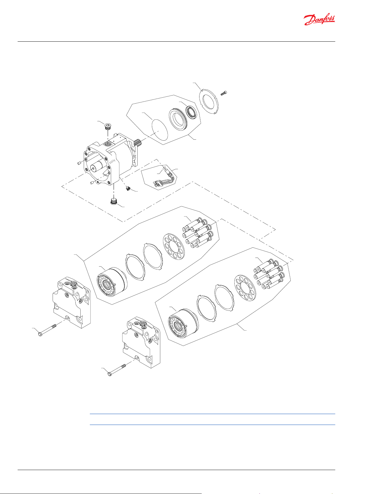
Series 90 Motors, 100cc
Common parts and special hardware
S90 100cc motor special hardware EAA, EBA, EFT
Parts configuration
Generic end cap used to show part location only
* Included in overhaul seal kit Q210
14 | © Danfoss | January 2020 AX00000094en-000204
Page 15
Parts Manual
Series 90 Motors, 100cc
Common parts and special hardware
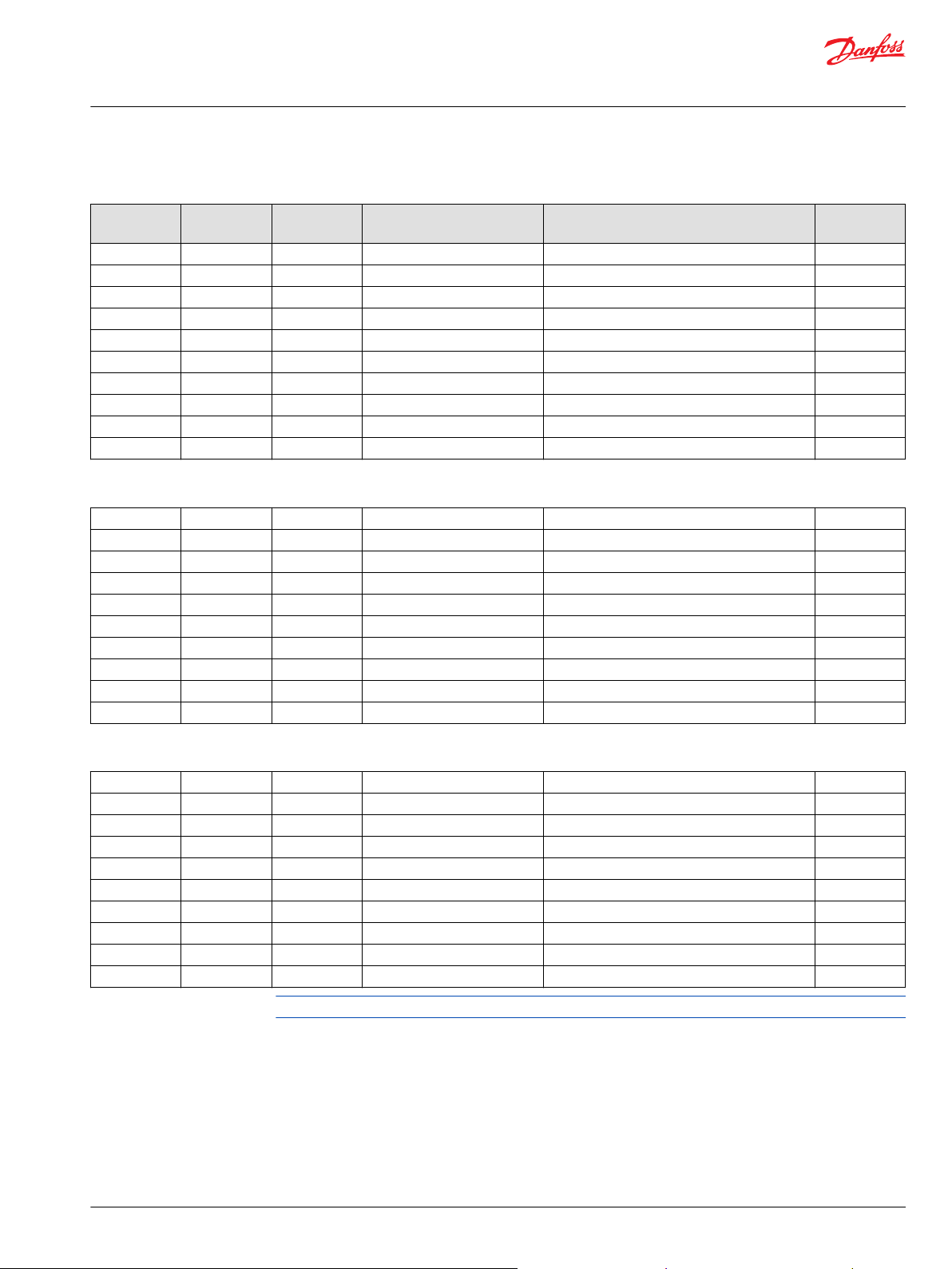
Order code: EAA
Item Date Begin Date End Part Number Part Name Quantity per
C06 94-14 11093925 (11012435) Cylinder block assembly with speed ring 1
C20 94-14 364000 Piston assembly 9
B83 94-14 KPPG12508 Speed sensor assembly 1
G96 94-14 307686 (9007210-1017) Screw, M10 x 80 1
L25 94-14 521722 Seal carrier assembly 1
L40 94-14 519021 Lip seal 1
L50 94-14 327627 (9004104-1540) O-ring 1
L60 94-14 516768 Retainer plate 1
QB83 94-14 085043 (9004201-3700) O-ring 1
QC04 94-14 8510395 Cylinder block kit, with speed ring 1
Q210 94-14 11134055 Overhaul seal kit, standard 1
Order code: EBA
C06 94-14 11093925 (11012435) Cylinder block assembly with speed ring 1
C20 94-14 364000 Piston assembly 9
B83 94-14 KPPG13408 Speed sensor assembly 1
G96 94-14 307686 (9007210-1017) Screw, M10 x 80 1
L25 94-14 521722 Seal carrier assembly 1
L40 94-14 519021 Lip seal 1
L50 94-14 327627 (9004104-1540) O-ring 1
L60 94-14 516768 Retainer plate 1
QB83 94-14 085043 (9004201-3700) O-ring 1
QC04 94-14 8510395 Cylinder block kit with speed ring 1
Q210 94-14 11134055 Overhaul seal kit, standard 1
Model/Kit
Order code: EFT
C06 17-33 11093925 (11012435) Cylinder block assembly with speed ring 1
C20 17-33 364000 Piston assembly 9
B83 17-33 KPPG16708 Speed sensor assembly 1
G96 17-33 307686 (9007210-1017) Screw, M10 x 80 1
L25 17-33 521722 Seal carrier assembly 1
L40 17-33 519021 Lip seal 1
L50 17-33 327627 (9004104-1540) O-ring 1
L60 17-33 516768 Retainer plate 1
QB83 17-33 085043 (9004201-3700) O-ring 1
QC04 17-33 8510395 Cylinder block kit with speed ring 1
Q210 17-33 11134055 Overhaul seal kit, standard 1
©
Danfoss | January 2020 AX00000094en-000204 | 15
Page 16
L60
L50
L40
*L25
B81
B80
C06
C20
QC04
G96
B83
*QB83
B83
Parts Manual
Series 90 Motors, 100cc
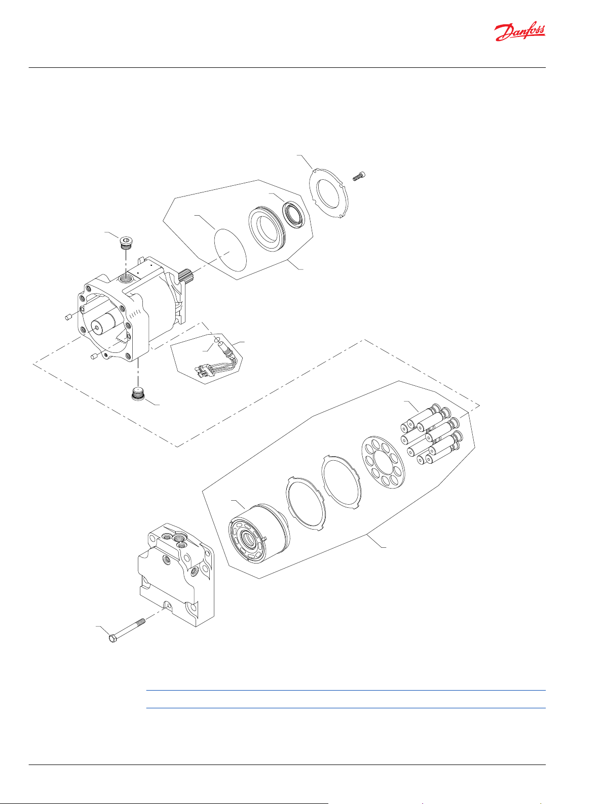
Common parts and special hardware
S90 100cc motor special hardware EBB-EEH
Parts configuration
Generic end cap used to show part location only
* Included in overhaul seal kit Q210
16 | © Danfoss | January 2020 AX00000094en-000204
Page 17
Parts Manual
Series 90 Motors, 100cc
Common parts and special hardware
Order code: EBB
Item Date Begin Date End Part Number Part Name Quantity per
C06 94-14 11093925 (11012435) Cylinder block assembly with speed ring 1
C20 94-14 364000 Piston assembly 9
B83 94-14 KPPG14408 Speed sensor assembly 1
G96 94-14 307686 (9007210-1017) Screw, M10 x 80 1
L25 94-14 521722 Seal carrier assembly 1
L40 94-14 519021 Lip seal 1
L50 94-14 327627 (9004104-1540) O-ring 1
L60 94-14 516768 Retainer plate 1
QB83 94-14 085043 (9004201-3700) O-ring 1
QC04 94-14 8510395 Cylinder block kit with speed ring 1
Q210 94-14 11134055 Overhaul seal kit, standard 1
Order code: EBF
C06 15-30 11093925 (11012435) Cylinder block assembly with speed ring 1
C20 15-30 364000 Piston assembly 9
B83 15-30 KPPG1A408 Speed sensor assembly 1
G96 15-30 307686 (9007210-1017) Screw, M10 x 80 1
L25 15-30 521722 Seal carrier assembly 1
L40 15-30 519021 Lip seal 1
L50 15-30 327627 (9004104-1540) O-ring 1
L60 15-30 516768 Retainer plate 1
QB83 15-30 085043 (9004201-3700) O-ring 1
QC04 15-30 8510395 Cylinder block kit with speed ring 1
Q210 15-30 11134055 Overhaul seal kit, standard 1
Model/Kit
Order code: EEA
C06 94-14 11093925 (11012435) Cylinder block assembly with speed ring 1
C20 94-14 364000 Piston assembly 9
B83 94-14 140644 Plug assembly 1
G96 94-14 307686 (9007210-1017) Screw, M10 x 80 1
L25 94-14 521722 Seal carrier assembly 1
L40 94-14 519021 Lip seal 1
L50 94-14 327627 (9004104-1540) O-ring 1
L60 94-14 516768 Retainer plate 1
QC04 94-14 8510395 Cylinder block kit with speed ring 1
Q210 94-14 11134055 Overhaul seal kit, standard 1
Parts continue to the next 2 pages.
©
Danfoss | January 2020 AX00000094en-000204 | 17
Page 18
L60
L50
L40
*L25
B81
B80
C06
C20
QC04
G96
B83
*QB83
B83
Parts Manual
Series 90 Motors, 100cc
Common parts and special hardware
Parts configuration
Generic end cap used to show part location only
* Included in overhaul seal kit Q210
18 | © Danfoss | January 2020 AX00000094en-000204
Page 19

Parts Manual
Series 90 Motors, 100cc
Common parts and special hardware
Order code: EEH
Item Date Begin Date End Part Number Part Name Quantity per
C06 14-15 11093925 (11012435) Cylinder block assembly with speed ring 1
C20 14-15 364000 Piston assembly 9
B83 14-15 140644 Plug assembly 1
G96 14-15 307686 (9007210-1017) Screw, M10 x 80 1
L25 14-15 521722 Seal carrier assembly 1
L40 14-15 519021 Lip seal 1
L50 14-15 327627 (9004104-1540) O-ring 1
L60 14-15 516768 Retainer plate 1
QC04 14-15 8510395 Cylinder block kit with speed ring 1
Q210 14-15 11134055 Overhaul seal kit, standard 1
Model/Kit
©
Danfoss | January 2020 AX00000094en-000204 | 19
Page 20

L60
L50
L40
*L25
B81
C06
C20
QC04
G96
B83
*QB83
B80
Parts Manual
Series 90 Motors, 100cc
Common parts and special hardware
S90 100cc motor special hardware EFA-EFM
Parts configuration
Generic end cap used to show part location only
* Included in overhaul seal kit Q210
20 | © Danfoss | January 2020 AX00000094en-000204
Page 21
Parts Manual
Series 90 Motors, 100cc
Common parts and special hardware
Order code: EFA
Item Date Begin Date End Part Number Part Name Quantity per
C06 94-14 11093925 (11012435) Cylinder block assembly with speed ring 1
C20 94-14 364000 Piston assembly 9
B83 94-14 KPPG136 Speed sensor assembly 1
G96 94-14 307686 (9007210-1017) Screw, M10 x 80 1
L25 94-14 521722 Seal carrier assembly 1
L40 94-14 519021 Lip seal 1
L50 94-14 327627 (9004104-1540) O-ring 1
L60 94-14 516768 Retainer plate 1
QB83 94-14 085043 (9004201-3700) O-ring 1
QC04 94-14 8510395 Cylinder block kit with speed ring 1
Q210 94-14 11134055 Overhaul seal kit, standard 1
Order code: EFB
C06 94-14 11093925 (11012435) Cylinder block assembly with speed ring 1
C20 94-14 364000 Piston assembly 9
B83 94-14 KPPG136 Speed sensor assembly 1
G96 94-14 307686 (9007210-1017) Screw, M10 x 80 1
L25 94-14 521722 Seal carrier assembly 1
L40 94-14 519021 Lip seal 1
L50 94-14 327627 (9004104-1540) O-ring 1
L60 94-14 516768 Retainer plate 1
QB83 94-14 085043 (9004201-3700) O-ring 1
QC04 94-14 8510395 Cylinder block kit with speed ring 1
Q210 94-14 11134055 Overhaul seal kit, standard 1
Model/Kit
Order code: EFJ
C06 94-14 11093925 (11012435) Cylinder block assembly with speed ring 1
C20 94-14 364000 Piston assembly 9
B83 94-14 KPPG176 Speed sensor assembly 1
G96 94-14 307686 (9007210-1017) Screw, M10 x 80 1
L25 94-14 521722 Seal carrier assembly 1
L40 94-14 519021 Lip seal 1
L50 94-14 327627 (9004104-1540) O-ring 1
L60 94-14 516768 Retainer plate 1
QB83 94-14 085043 (9004201-3700) O-ring 1
QC04 94-14 8510395 Cylinder block kit with speed ring 1
Q210 94-14 11134055 Overhaul seal kit, standard 1
Parts continue to the next 2 pages.
©
Danfoss | January 2020 AX00000094en-000204 | 21
Page 22
L60
L50
L40
*L25
B81
C06
C20
QC04
G96
B83
*QB83
B80
Parts Manual
Series 90 Motors, 100cc
Common parts and special hardware
Parts configuration
Generic end cap used to show part location only
* Included in overhaul seal kit Q210
22 | © Danfoss | January 2020 AX00000094en-000204
Page 23

Parts Manual
Series 90 Motors, 100cc
Common parts and special hardware
Order code: EFM
Item Date Begin Date End Part Number Part Name Quantity per
C06 14-36 11093925 (11012435) Cylinder block assembly with speed ring 1
C20 14-36 364000 Piston assembly 9
B83 14-36 KPPG12730A Speed sensor assembly 1
G96 14-36 307686 (9007210-1017) Screw, M10 x 80 1
L25 14-36 521722 Seal carrier assembly 1
L40 14-36 519021 Lip seal 1
L50 14-36 327627 (9004104-1540) O-ring 1
L60 14-36 516768 Retainer plate 1
QB83 14-36 085043 (9004201-3700) O-ring 1
QC04 14-36 8510395 Cylinder block kit with speed ring 1
Q210 14-36 11134055 Overhaul seal kit, standard 1
Model/Kit
©
Danfoss | January 2020 AX00000094en-000204 | 23
Page 24
B83
L60
C20
QC04
C05
L50
L40
*L25
B81
C06
C20
QC04
G96
G96
B83
*QB83
B80
Parts Manual
Series 90 Motors, 100cc
Common parts and special hardware
S90 100cc motor special hardware EGL-JAB
Parts configuration
Generic end cap used to show part location only
* Included in overhaul seal kit Q210
24 | © Danfoss | January 2020 AX00000094en-000204
Page 25

Parts Manual
Series 90 Motors, 100cc
Common parts and special hardware
Order code: EGL
Item Date Begin Date End Part Number Part Name Quantity per
C06 10-34 11093925 (11012435) Cylinder block assembly with speed ring 1
C20 10-34 364000 Piston assembly 9
B83 10-34 KPPG16719 Speed sensor assembly 1
G96 10-34 307686 (9007210-1017) Screw, M10 x 80 1
L25 10-34 521722 Seal carrier assembly 1
L40 10-34 519021 Lip seal 1
L50 10-34 327627 (9004104-1540) O-ring 1
L60 10-34 516768 Retainer plate 1
QB83 10-34 085043 (9004201-3700) O-ring 1
QC04 10-34 8510395 Cylinder block kit with speed ring 1
Q210 10-34 11134055 Overhaul seal kit, standard 1
Order code: EHD
C06 94-14 11093925 (11012435) Cylinder block assembly with speed ring 1
C20 94-14 364000 Piston assembly 9
B83 94-14 KPPG16408 Speed sensor assembly 1
G96 94-14 307686 (9007210-1017) Screw, M10 x 80 1
L25 94-14 521722 Seal carrier assembly 1
L40 94-14 519021 Lip seal 1
L50 94-14 327627 (9004104-1540) O-ring 1
L60 94-14 516768 Retainer plate 1
QB83 94-14 085043 (9004201-3700) O-ring 1
QC04 94-14 8510395 Cylinder block kit with speed ring 1
Q210 94-14 11134055 Overhaul seal kit, standard 1
Model/Kit
Order code: GTA
C05 14-26 519257 (11012434) Cylinder block assembly 1
C20 14-26 364000 Piston assembly 9
B83 14-26 140644 Plug assembly 1
G96 14-26 307686 (9007210-1017) Screw, M10 x 80 1
L25 14-26 521722 Seal carrier assembly 1
L40 14-26 519021 Lip seal 1
L50 14-26 327627 (9004104-1540) O-ring 1
L60 14-26 516768 Retainer plate 1
QC04 14-26 8510370 Cylinder block kit 1
Q210 14-26 11134055 Overhaul seal kit, standard 1
Parts continue to the next 2 pages.
©
Danfoss | January 2020 AX00000094en-000204 | 25
Page 26
B83
L60
C20
QC04
C05
L50
L40
*L25
B81
C06
C20
QC04
G96
G96
B83
*QB83
B80
Parts Manual
Series 90 Motors, 100cc
Common parts and special hardware
Parts configuration
Generic end cap used to show part location only
* Included in overhaul seal kit Q210
26 | © Danfoss | January 2020 AX00000094en-000204
Page 27

Parts Manual
Series 90 Motors, 100cc
Common parts and special hardware
Order code: JAB
Item Date Begin Date End Part Number Part Name Quantity per
C05 94-14 519257 (11012434) Cylinder block assembly 1
C20 94-14 364000 Piston assembly 9
B83 94-14 140644 Plug assembly 1
G96 94-14 307686 (9007210-1017) Screw, M10 x 80 1
L25 94-14 521722 Seal carrier assembly 1
L40 94-14 519021 Lip seal 1
L50 94-14 327627 (9004104-1540) O-ring 1
L60 94-14 516768 Retainer plate 1
QC04 94-14 8510370 Cylinder block kit 1
Q210 94-14 11134055 Overhaul seal kit, standard 1
Model/Kit
©
Danfoss | January 2020 AX00000094en-000204 | 27
Page 28

L60
L50
L40
*L25
B81
B80
C20
QC04
G96
B83
C05
Parts Manual
Series 90 Motors, 100cc
Common parts and special hardware
S90 100cc motor special hardware JAE-JCB
Parts configuration
Generic end cap used to show part location only
* Included in overhaul seal kit Q210
28 | © Danfoss | January 2020 AX00000094en-000204
Page 29
Parts Manual
Series 90 Motors, 100cc
Common parts and special hardware
Order code: JAE
Item Date Begin Date End Part Number Part Name Quantity per
C05 15-44 519257 (11012434) Cylinder block assembly 1
C20 15-44 364000 Piston assembly 9
B83 15-44 140644 Plug assembly 1
G96 15-44 307686 (9007210-1017) Screw, M10 x 80 1
L25 15-44 521722 Seal carrier assembly 1
L40 15-44 519021 Lip seal 1
L50 15-44 327627 (9004104-1540) O-ring 1
L60 15-44 516768 Retainer plate 1
QC04 15-44 8510370 Cylinder block kit 1
Q210 15-44 11134055 Overhaul seal kit, standard 1
Order code: JAF
C05 94-14 519257 (11012434) Cylinder block assembly 1
C20 94-14 364000 Piston assembly 9
B83 94-14 140644 Plug assembly 1
G96 94-14 307686 (9007210-1017) Screw, M10 x 80 1
L25 94-14 521722 Seal carrier assembly 1
L40 94-14 519021 Lip seal 1
L50 94-14 327627 (9004104-1540) O-ring 1
L60 94-14 516768 Retainer plate 1
QC04 94-14 8510370 Cylinder block kit 1
Q210 94-14 11134055 Overhaul seal kit, standard 1
Model/Kit
Order code: JAH
C05 94-14 519257 (11012434) Cylinder block assembly 1
C20 94-14 364000 Piston assembly 9
B83 94-14 140644 Plug assembly 1
G96 94-14 307686 (9007210-1017) Screw, M10 x 80 1
L25 94-14 521722 Seal carrier assembly 1
L40 94-14 519021 Lip seal 1
L50 94-14 327627 (9004104-1540) O-ring 1
L60 94-14 516768 Retainer plate 1
QC04 94-14 8510370 Cylinder block kit 1
Q210 94-14 11134055 Overhaul seal kit, standard 1
Parts continue to the next 2 pages.
©
Danfoss | January 2020 AX00000094en-000204 | 29
Page 30
L60
L50
L40
*L25
B81
B80
C20
QC04
G96
B83
C05
Parts Manual
Series 90 Motors, 100cc
Common parts and special hardware
Parts configuration
Generic end cap used to show part location only
* Included in overhaul seal kit Q210
30 | © Danfoss | January 2020 AX00000094en-000204
Page 31

Parts Manual
Series 90 Motors, 100cc
Common parts and special hardware
Order code: JCB
Item Date Begin Date End Part Number Part Name Quantity per
C05 94-14 519257 (11012434) Cylinder block assembly 1
C20 94-14 364000 Piston assembly 9
B83 94-14 140644 Plug assembly 1
G96 94-14 307686 (9007210-1017) Screw, M10 x 80 1
L25 94-14 521722 Seal carrier assembly 1
L40 94-14 519021 Lip seal 1
L50 94-14 327627 (9004104-1540) O-ring 1
L60 94-14 516768 Retainer plate 1
QC04 94-14 8510370 Cylinder block kit 1
Q210 94-14 11134055 Overhaul seal kit, standard 1
Model/Kit
©
Danfoss | January 2020 AX00000094en-000204 | 31
Page 32

B83
L60
C20
QC04
C05
L50
L40
*L25
B81
C06
C20
QC04
G96
G96
B83
*QB83
B80
(NNN)
(LAB & LAC)
Parts Manual
Series 90 Motors, 100cc
Common parts and special hardware
S90 100cc motor special hardware LAB-NNN
Parts configuration
Generic end cap used to show part location only
* Included in overhaul seal kit Q210
32 | © Danfoss | January 2020 AX00000094en-000204
Page 33

Parts Manual
Series 90 Motors, 100cc
Common parts and special hardware
Order code: LAB
Item Date Begin Date End Part Number Part Name Quantity per
C06 94-14 11012436 Cylinder block assembly with speed ring 1
C20 94-14 364000 Piston assembly 9
B83 94-14 KPPG14408 Speed sensor assembly 1
G96 94-14 307686 (9007210-1017) Screw, M10 x 80 1
L25 94-14 521722 Seal carrier assembly 1
L40 94-14 519021 Lip seal 1
L50 94-14 327627 (9004104-1540) O-ring 1
L60 94-14 516768 Retainer plate 1
QB83 94-14 085043 (9004201-3700) O-ring 1
QC04 94-14 11135418 Cylinder block kit with speed ring 1
Q210 94-14 11134055 Overhaul seal kit, standard 1
Order code: LAC
C06 94-14 11012436 Cylinder block assembly with speed ring 1
C20 94-14 364000 Piston assembly 9
B83 94-14 140644 Plug assembly 1
G96 94-14 307686 (9007210-1017) Screw, M10 x 80 1
L25 94-14 521722 Seal carrier assembly 1
L40 94-14 519021 Lip seal 1
L50 94-14 327627 (9004104-1540) O-ring 1
L60 94-14 516768 Retainer plate 1
QC04 94-14 11135418 Cylinder block kit with speed ring 1
Q210 94-14 11134055 Overhaul seal kit, standard 1
Model/Kit
Order code: NNN
C05 94-14 519257 (11012434) Cylinder block assembly 1
C20 94-14 364000 Piston assembly 9
B83 94-14 140644 Plug assembly 1
G96 94-14 307686 (9007210-1017) Screw, M10 x 80 1
L25 94-14 521722 Seal carrier assembly 1
L40 94-14 519021 Lip seal 1
L50 94-14 327627 (9004104-1540) O-ring 1
L60 94-14 516768 Retainer plate 1
QC04 94-14 8510370 Cylinder block kit 1
Q210 94-14 11134055 Overhaul seal kit, standard 1
©
Danfoss | January 2020 AX00000094en-000204 | 33
Page 34

B83
L60
C20
QC04
C05
L50
L40
*L25
B81
C06
C20
QC04
G96
G96
B83
*QB83
B80
(PAA)
(PAB)
Parts Manual
Series 90 Motors, 100cc
Common parts and special hardware
S90 100cc motor special hardware PAA, PAB
Parts configuration
Generic end cap used to show part location only
* Included in overhaul seal kit Q210
34 | © Danfoss | January 2020 AX00000094en-000204
Page 35

Parts Manual
Series 90 Motors, 100cc
Common parts and special hardware
Order code: PAA
Item Date Begin Date End Part Number Part Name Quantity per
C05 94-14 519257 (11012434) Cylinder block assembly 1
C20 94-14 364000 Piston assembly 9
B83 94-14 140644 Plug assembly 1
G96 94-14 307686 (9007210-1017) Screw, M10 x 80 1
L25 94-14 521722 Seal carrier assembly 1
L40 94-14 519021 Lip seal 1
L50 94-14 327627 (9004104-1540) O-ring 1
L60 94-14 516768 Retainer plate 1
QC04 94-14 8510370 Cylinder block kit 1
Q210 94-14 11134055 Overhaul seal kit, standard 1
Order code: PAB
C06 10-16 11093925 (11012435) Cylinder block assembly with speed ring 1
C20 10-16 364000 Piston assembly 9
B83 10-16 KPPG16719 Speed sensor assembly 1
G96 10-16 509487 Screw, M10 x 100 1
L25 10-16 521722 Seal carrier assembly 1
L40 10-16 519021 Lip seal 1
L50 10-16 327627 (9004104-1540) O-ring 1
L60 10-16 516768 Retainer plate 1
QB83 10-16 085043 (9004201-3700) O-ring 1
QC04 10-16 8510395 Cylinder block kit with speed ring 1
Q210 10-16 11134055 Overhaul seal kit, standard 1
Model/Kit
©
Danfoss | January 2020 AX00000094en-000204 | 35
Page 36

G04
G70
G04
G20
G70
G80
G81
G20
G04
G70
G20
G51
G50
G51
G50
G51
G50
(1, 8 & D)
(3 & 7)
(E)
Parts Manual
Series 90 Motors, 100cc
End cap
S90 100cc motor end cap 1-8, D, E
Parts configuration
* Included in overhaul seal kit Q210
36 | © Danfoss | January 2020 AX00000094en-000204
Page 37

Parts Manual
Series 90 Motors, 100cc
End cap
Order code: 1
Item Date Begin Date End Part Number Part Name Quantity per
G04 90-20 8200581 End cap assembly, twin (SB-1988-018 on page
57, SB-1989-020 on page 61, SB-1998-007 on
page 64)
G20 87-02 11017304 (8700030) Journal bearing 1
G50 87-02 140644 Plug assembly 1
G51 87-02 140644 Plug assembly 1
G70 87-02 140644 Plug assembly 1
Order code: 3
G04 90-20 8200582 End cap assembly, axial (SB-1988-018 on page
57, SB-1989-020 on page 61, SB-1998-007 on
page 64)
G20 87-02 11017304 (8700030) Journal bearing 1
G50 87-02 140644 Plug assembly 1
G51 87-02 140644 Plug assembly 1
G70 87-02 140644 Plug assembly 1
Model/Kit
1
1
Order code: 7
G04 90-20 8200582 End cap assembly, axial (SB-1988-018 on page
57, SB-1989-020 on page 61, SB-1998-007 on
page 64)
G20 87-02 11017304 (8700030) Journal bearing 1
G50 87-02 140644 Plug assembly 1
G51 87-02 140644 Plug assembly 1
G70 87-02 140644 Plug assembly 1
Order code: 8
G04 90-20 8200581 End cap assembly, twin (SB-1988-018 on page
57, SB-1989-020 on page 61, SB-1998-007 on
page 64)
G20 87-02 11017304 (8700030) Journal bearing 1
G50 87-02 140644 Plug assembly 1
G51 87-02 140644 Plug assembly 1
G70 87-02 140644 Plug assembly 1
Parts continue to the next 2 pages.
1
1
©
Danfoss | January 2020 AX00000094en-000204 | 37
Page 38

G04
G70
G04
G20
G70
G80
G81
G20
G04
G70
G20
G51
G50
G51
G50
G51
G50
(1, 8 & D)
(3 & 7)
(E)
Parts Manual
Series 90 Motors, 100cc
End cap
Parts configuration
* Included in overhaul seal kit Q210
38 | © Danfoss | January 2020 AX00000094en-000204
Page 39

Parts Manual
Series 90 Motors, 100cc
End cap
Order code: D
Item Date Begin Date End Part Number Part Name Quantity per
G04 99-09 11064118 End cap assembly, twin 1
G20 99-09 11017304 (8700030) Journal bearing 1
G50 99-09 140644 Plug assembly 1
G51 99-09 140644 Plug assembly 1
G70 99-09 140644 Plug assembly 1
Order code: E
G04 95-17 8200562 End cap assembly, twin (SB-1998-007 on page
64)
G20 95-17 11017304 (8700030) Journal bearing 1
G50 95-17 140644 Plug assembly 1
G51 95-17 140644 Plug assembly 1
G70 95-17 140644 Plug assembly 1
G80 95-17 664524 (9005110-9000) Plug assembly 1
G81 95-17 664524 (9005110-9000) Plug assembly 1
Model/Kit
1
©
Danfoss | January 2020 AX00000094en-000204 | 39
Page 40

G04
G20
G70
G51
G50
G24
G22
G21
G31
G23
G29
G59
G04
G70
G50
G57
G51
G58
G20
G04
G70
G51
G50
G29
G59
G57
G20
M200
QM36
QM34
G32
(F)
(G & Q)
(M)
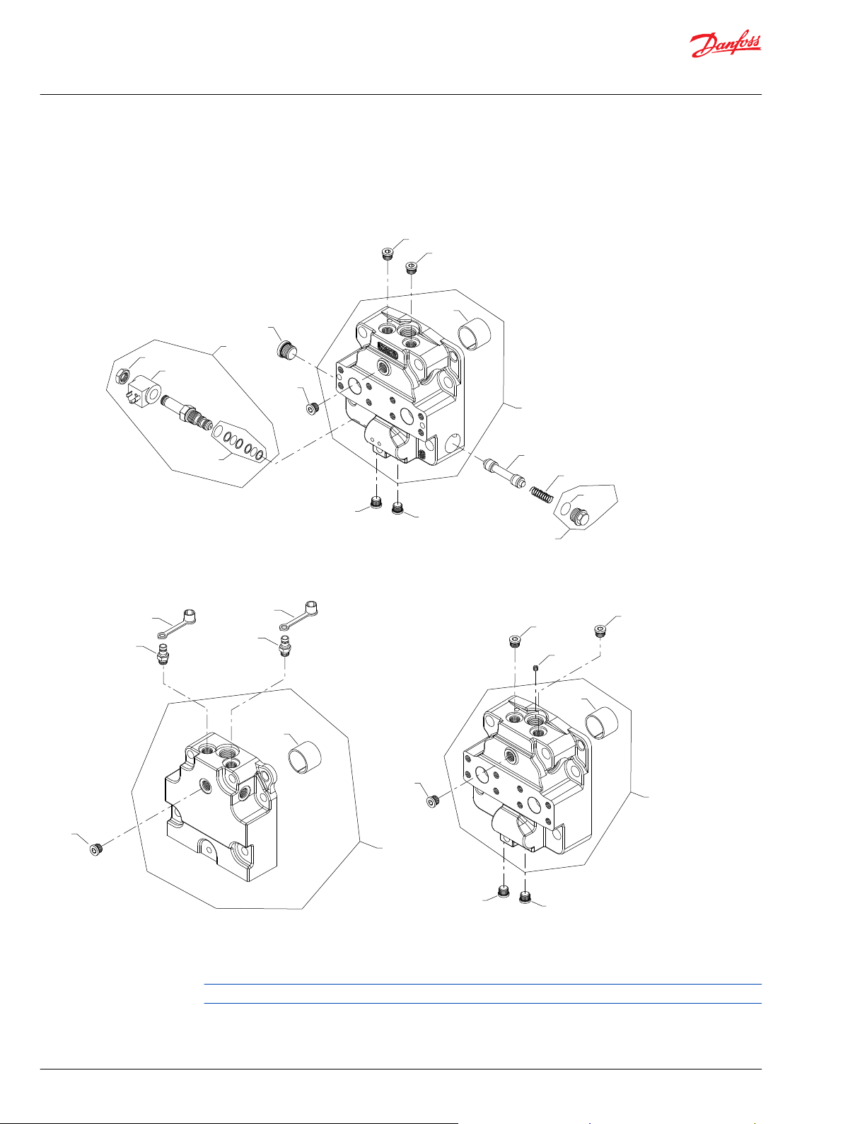
Parts Manual
Series 90 Motors, 100cc
End cap
S90 100cc motor end cap F-Q
Parts configuration
Generic coils shown.
40 | © Danfoss | January 2020 AX00000094en-000204
Page 41

Parts Manual
Series 90 Motors, 100cc
End cap
Order code: F
Item Date Begin Date End Part Number Part Name Quantity per
G04 99-09 507659/P End cap assembly, axial ports 1
G20 99-09 11017304 (8700030) Journal bearing 1
G21 99-09 507587 Spool 1
G22 99-09 507534 Spring 1
G23 99-09 511926 Plug assembly 1
G24 99-09 012559 O-ring 1
G29 99-09 140644 Plug assembly 1
G31 99-09 315325 Plug assembly 1
G32 99-09 784942/P Solenoid valve. 12v 1
G50 99-09 140644 Plug assembly 1
G51 99-09 140644 Plug assembly 1
G59 99-09 140644 Plug assembly 1
G70 99-09 140644 Plug assembly 1
M200 99-09 785196 Coil, 12v, DIN connector 1
QM34 99-09 11144220 Solenoid seal kit 1
QM36 99-09 11144221 Coil nut 1
Model/Kit
Order code: G
G04 98-02 11064118 End cap assembly, twin metric ports 1
G20 98-02 11017304 (8700030) Journal bearing 1
G50 98-02 8700127 Diagnostic receptacle 1
G51 98-02 8700127 Diagnostic receptacle 1
G57 98-02 8700128 Dust cover 1
G58 98-02 8700128 Dust cover 1
G70 98-02 140644 Plug assembly 1
Parts continue to the next 2 pages.
©
Danfoss | January 2020 AX00000094en-000204 | 41
Page 42
G04
G20
G70
G51
G50
G24
G22
G21
G31
G23
G29
G59
G04
G70
G50
G57
G51
G58
G20
G04
G70
G51
G50
G29
G59
G57
G20
M200
QM36
QM34
G32
(F)
(G & Q)
(M)
Parts Manual
Series 90 Motors, 100cc
End cap
Parts configuration
Generic coils shown.
42 | © Danfoss | January 2020 AX00000094en-000204
Page 43

Parts Manual
Series 90 Motors, 100cc
End cap
Order code: M
Item Date Begin Date End Part Number Part Name Quantity per
G04 98-02 11133008 End cap assembly, axial metric ports 1
G20 98-02 11127356 Journal bearing 1
G29 98-02 140644 Plug assembly 1
G50 98-02 140644 Plug assembly 1
G51 98-02 140644 Plug assembly 1
G57 98-02 517100 Orifice plug 1
G59 98-02 140644 Plug assembly 1
G70 98-02 140644 Plug assembly 1
Order code: Q
G04 98-02 11064118 End cap assembly, twin metric ports 1
G20 98-02 11017304 (8700030) Journal bearing 1
G50 98-02 8700127 Diagnostic receptacle 1
G51 98-02 8700127 Diagnostic receptacle 1
G57 98-02 8700128 Dust cover 1
G58 98-02 8700128 Dust cover 1
G70 98-02 140644 Plug assembly 1
Model/Kit
©
Danfoss | January 2020 AX00000094en-000204 | 43
Page 44

G04
G20
G70
G51
G50
G29
G33
G31
G24
G23
G22
G21
G59
G04
G70
G51
G50
G24
G22
G21
G31
G23
G29
G59
G20
G32
M200
QM36
QM34
(T)
(U)
Parts Manual
Series 90 Motors, 100cc
End cap
S90 100cc motor end cap T, U
Parts configuration
44 | © Danfoss | January 2020 AX00000094en-000204
Generic coils shown.
Page 45

Parts Manual
Series 90 Motors, 100cc
End cap
Order code: T
Item Date Begin Date End Part Number Part Name Quantity per
G04 99-09 513899/P End cap assembly, axial ports 1
G20 99-09 11017304 (8700030) Journal bearing 1
G21 99-09 507587 Spool 1
G22 99-09 507534 Spring 1
G23 99-09 511926 Plug assembly 1
G24 99-09 012559 O-ring 1
G29 99-09 140644 Plug assembly 1
G31 99-09 315325 (9005110-8700) Plug assembly 1
G33 99-09 327007 (9005110-4400) Plug assembly 1
G50 99-09 140644 Plug assembly 1
G51 99-09 140644 Plug assembly 1
G59 99-09 140644 Plug assembly 1
G70 99-09 140644 Plug assembly 1
Model/Kit
Order code: U
G04 99-09 516298/P End cap assembly, axial 1
G20 99-09 11017304 (8700030) Journal bearing 1
G21 99-09 507587 Spool 1
G22 99-09 507534 Spring 1
G23 99-09 511926 Plug assembly 1
G24 99-09 012559 O-ring 1
G29 99-09 140644 Plug assembly 1
G31 99-09 315325 Plug assembly 1
G32 99-09 517171/P Solenoid valve, 12v 1
G59 99-09 140644 Plug assembly 1
G50 99-09 140644 Plug assembly 1
G51 99-09 140644 Plug assembly 1
G70 99-09 140644 Plug assembly 1
M200 99-09 517167 Coil, 12v, Weather-Pack 1
QM34 99-09 11144220 Solenoid seal kit 1
QM36 99-09 11144221 Coil nut 1
©
Danfoss | January 2020 AX00000094en-000204 | 45
Page 46
G100
SR1
ST1
S100
SR1A
G04
G20
G70
G51
G50
SDR1
SPA1
SPB1
SL01
ST1A
SE2
SE1
SE1A
G04
*G20
G70
G51
G50
G29
G59
(V)
(W & X)
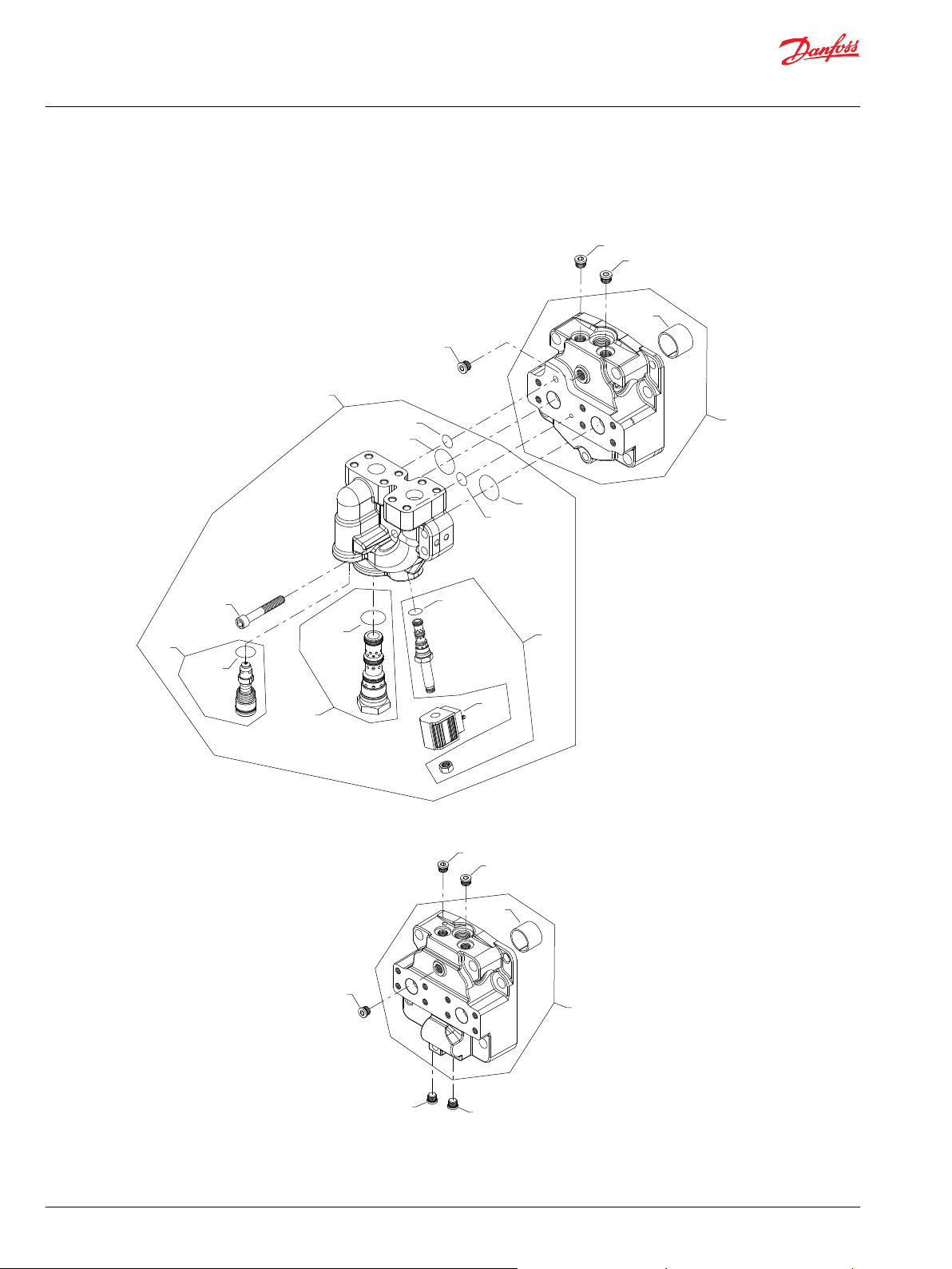
Parts Manual
Series 90 Motors, 100cc
End cap
S90 100cc motor end cap V-X
Parts configuration
46 | © Danfoss | January 2020 AX00000094en-000204
Page 47
Parts Manual
Series 90 Motors, 100cc
End cap
Order code: V
Item Date Begin Date End Part Number Part Name Quantity per
G04 98-02 518212/P End cap assembly, axial ports 1
G20 98-02 11017304 (8700030) Journal bearing 1
G50 98-02 140644 Plug assembly 1
G51 98-02 140644 Plug assembly 1
G70 98-02 140644 Plug assembly 1
G100 98-02 9007300-4432 Screw 6
S100 98-02 518083 Valve housing assembly 1
SDR1 98-02 518149 O-ring 1
SE1 98-02 518961 Solenoid pilot valve 1
SE1A 98-02 516735 Seal ring 1
SE2 98-02 520344 Coil, 12v 1
SL01 98-02 518149 O-ring 1
SPA1 98-02 516756 O-ring 1
SPB1 98-02 516756 O-ring 1
SR1 98-02 516970 Valve 1
SR1A 98-02 518151 O-ring 1
ST1 98-02 518052 Bypass valve 1
ST1A 98-02 518150 O-ring 1
Model/Kit
Order code: W
G04 99-09 519388/P End cap assembly, axial ports 1
G20 99-09 11017304 (8700030) Journal bearing 1
G29 99-09 140644 Plug assembly 1
G50 99-09 140644 Plug assembly 1
G51 99-09 140644 Plug assembly 1
G59 99-09 140644 Plug assembly 1
G70 99-09 140644 Plug assembly 1
Order code: X
G04 98-02 11040386 End cap assembly, axial ports 1
G20 98-02 11017304 (8700030) Journal bearing 1
G29 99-09 140644 Plug assembly 1
G50 99-09 140644 Plug assembly 1
G51 99-09 140644 Plug assembly 1
G59 99-09 140644 Plug assembly 1
G70 99-09 140644 Plug assembly 1
©
Danfoss | January 2020 AX00000094en-000204 | 47
Page 48

H50
H20
*H90
H30
H55
H50
H55
H20
*H90
H30
H10
H50
H20
*H90
H30
H55
H10
H50
H50
H10
*QH50
*QH50
H10
H50
H55
H20
*H90
H30
H30
H20
H30
H20
H600
H500
(B)
(C)
(N)
(W)
(B)
(C)
(N)
(W)
Parts Manual
Series 90 Motors, 100cc
Loop flushing
S90 100cc motor loop flushing B-W
Parts configuration
Generic end cap used to show part location only
* Included in overhaul seal kit Q210
48 | © Danfoss | January 2020 AX00000094en-000204
Page 49
Parts Manual
Series 90 Motors, 100cc
Loop flushing
Order code: B
Item Date Begin Date End Part Number Part Name Quantity per
H10 00-14 516301 Loop flushing spool 1
H20 00-14 517438 Spring guide 2
H30 00-14 517439 Spring 2
H50 00-14 517436 Spring cartridge assembly 2
H55 00-14 140644 Plug assembly 1
H90 00-14 085043 (9004201-3700) O-ring 2
Order code: C
H10 03-16 519242 Loop flushing spool 1
H20 03-16 517438 Spring guide 2
H30 03-16 517439 Spring 2
H50 03-16 517436 Spring cartridge assembly 2
H55 03-16 140644 Plug assembly 1
H90 03-16 085043 (9004201-3700) O-ring 2
Model/Kit
Order code: K
H10 89-38 365544 (8800550) Shuttle spool 1
H50 89-38 518016 Plug assembly 2
H300 89-38 513596 Spring guide assembly (SB-2000-047 on page
68)
QH50 87-07 085043 (9004201-3700) O-ring 2
Order code: N
H10 89-38 8800668 Loop flushing spool, defeated 1
H10 87-07 89-37 308486 (8800021) Loop flushing spool, defeated (SB-1989-020 on
page 61)
H50 87-07 140644 Plug assembly 2
H50A 87-07 085043 (9004201-3700) O-ring 2
Order code: W
H10 89-38 365544 (8800550) Shuttle spool 1
H10 89-38 89-37 674473 (8800069) Loop flushing spool (SB-1989-020 on page 61) 1
H20 87-07 89-37 674481 (8800265) Spring guide (SB-1989-020 on page 61) 2
H30 87-07 89-37 8800067 Spring (SB-1989-020 on page 61) 2
H50 87-07 89-37 674507 (9005475-0069) Plug assembly (SB-1989-020 on page 61) 2
H500 17-33 11160971 Plug/spring assembly 1
H600 17-33 11160971 Plug/spring assembly 1
QH50 87-07 085043 (9004201-3700) O-ring 2
2
1
©
Danfoss | January 2020 AX00000094en-000204 | 49
Page 50

K10
*K50
*K51
QK10
*K50
*K50
QK10
(00)
(20 & 24)
(A0-N6)
Parts Manual
Series 90 Motors, 100cc
Charge pressure setting
S90 100cc motor charge pressure setting 00-N6
Parts configuration
Generic end cap used to show part location only
* Included in overhaul seal kit Q210
50 | © Danfoss | January 2020 AX00000094en-000204
Page 51

Parts Manual
Series 90 Motors, 100cc
Charge pressure setting
Order code: 00
Item Date Begin Date End Part Number Part Name Quantity per
K10 89-44 001537 (9005100-8700) Plug assembly 1
K50 89-44 001149 (9004201-6200) O-ring 1
Order code: 20-24
K000 90-20 8510012 Adjustable charge relief valve kit (SB-1989-020 on
page 61)
K50 90-20 001149 (9004201-6200) O-ring 1
Order code: A0
QK10 98-19 8510253 Cartridge CPRV kit, 13 bar, 11 L/min 1
K50 98-19 001149 (9004201-6200) O-ring 1
K51 98-19 085043 (9004201-3700) O-ring 1
Order code: A3
QK10 98-19 8510256 Cartridge CPRV kit, 13 bar, 16 L/min 1
K50 98-19 001149 (9004201-6200) O-ring 1
K51 98-19 085043 (9004201-3700) O-ring 1
Model/Kit
1
Order code: E4
QK10 98-19 8510261 Cartridge CPRV kit, 16 bar, 4 L/min 1
K50 98-19 001149 (9004201-6200) O-ring 1
K51 98-19 085043 (9004201-3700) O-ring 1
Order code: E6
QK10 98-19 8510252 Cartridge CPRV kit, 16 bar, 7 L/min 1
K50 98-19 001149 (9004201-6200) O-ring 1
K51 98-19 085043 (9004201-3700) O-ring 1
Order code: F0
QK10 98-19 8510259 Cartridge CPRV kit, 16 bar, 11 L/min 1
K50 98-19 001149 (9004201-6200) O-ring 1
K51 98-19 085043 (9004201-3700) O-ring 1
Order code: F3
QK10 98-19 8510262 Cartridge CPRV kit, 16 bar, 16 L/min 1
K50 98-19 001149 (9004201-6200) O-ring 1
K51 98-19 085043 (9004201-3700) O-ring 1
Parts continue to the next 2 pages.
©
Danfoss | January 2020 AX00000094en-000204 | 51
Page 52

K10
*K50
*K51
QK10
*K50
*K50
QK10
(00)
(20 & 24)
(A0-N6)
Parts Manual
Series 90 Motors, 100cc
Charge pressure setting
Parts configuration
Generic end cap used to show part location only
* Included in overhaul seal kit Q210
52 | © Danfoss | January 2020 AX00000094en-000204
Page 53
Parts Manual
Series 90 Motors, 100cc
Charge pressure setting
Order code: G0
Item Date Begin Date End Part Number Part Name Quantity per
QK10 98-19 8510260 Cartridge CPRV kit, 16 bar, 22 L/min 1
K50 98-19 001149 (9004201-6200) O-ring 1
K51 98-19 085043 (9004201-3700) O-ring 1
Order code: G3
QK10 98-19 8510263 Cartridge CPRV kit, 16 bar, 27 L/min 1
K50 98-19 001149 (9004201-6200) O-ring 1
K51 98-19 085043 (9004201-3700) O-ring 1
Order code: N4
QK10 98-19 8510255 Cartridge CPRV kit, 13 bar, 4 L/min 1
K50 98-19 001149 (9004201-6200) O-ring 1
K51 98-19 085043 (9004201-3700) O-ring 1
Model/Kit
Order code: N6
QK10 98-19 11097072 Cartridge CPRV kit, 13 bar, 7 L/min 1
K50 98-19 001149 (9004201-6200) O-ring 1
K51 98-19 085043 (9004201-3700) O-ring 1
©
Danfoss | January 2020 AX00000094en-000204 | 53
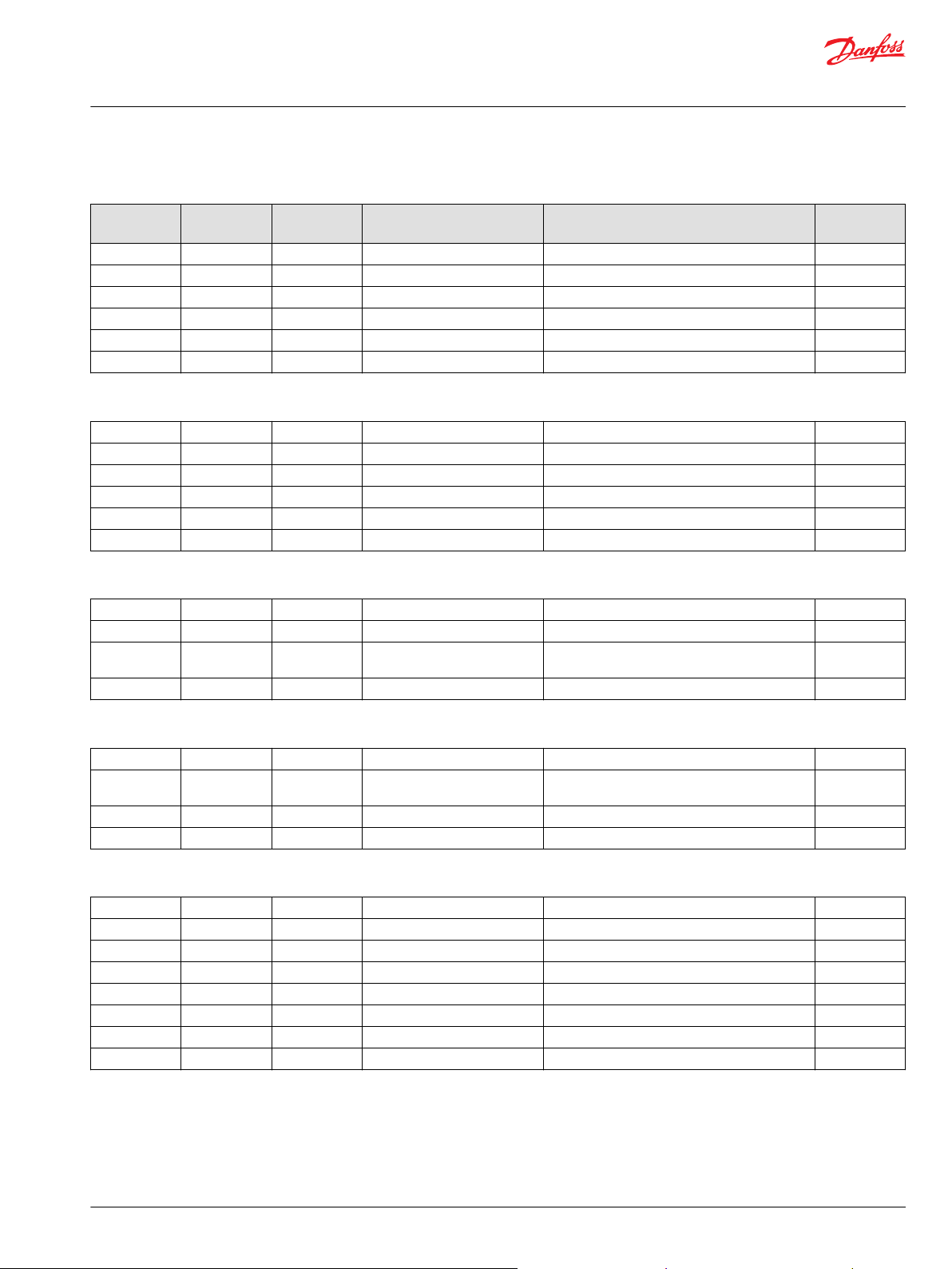
Page 54
L100
L100
L80
L100
L100
L100
L80
L90
L61
L100
L500
L200
L90
(C6, C7, F1, G7, S1)
(K3)
(L1)
(S5)
(T2)
(TJ)
Parts Manual
Series 90 Motors, 100cc
Shaft
S90 100cc motor shaft C6-TJ
Parts configuration
54 | © Danfoss | January 2020 AX00000094en-000204
Page 55

Parts Manual
Series 90 Motors, 100cc
Shaft
Order code: C6
Item Date Begin Date End Part Number Part Name Quantity per
L100 87-07 11045036 Shaft, 21 tooth spline, 16/32 1
Order code: C7
L100 87-07 8200591 Shaft, 23 tooth spline, 16/32 1
Order code: F1
L100 87-07 8200597 Shaft, 13 tooth spline, 8/16 1
Order code: G7
L100 05-21 8200591 Shaft, 23 tooth spline, 16/32 1
Order code: K3
L100 87-07 11012428 Shaft, straight key 1
L80 87-07 9003261-3724 Key, .375 x 1.5 1
Model/Kit
Order code: L1
L100 10-15 11081469 Shaft, 27 tooth spline, 12/24, special length 1
Order code: S1
L100 87-07 11012429 Shaft, 14 tooth spline, 12/24 1
Order code: S5
L100 87-07 11014534 Shaft, 17 tooth spline, 12/24 1
Order code: T2
L100 87-02 11014535 Shaft, tapered 1
L61 87-02 9004600-1230 Cotter pin 1
L80 87-02 9003310-3724 Woodruff key, .3730 x 1.5 1
L90 87-02 5000606 Slotted nut 1
Order code: TJ
L90 97-47 504060 Nut 1
L100 97-47 511785 Shaft, tapered 1
L200 97-47 511462 Flange coupling 1
L500 97-47 511627 Washer 1
©
Danfoss | January 2020 AX00000094en-000204 | 55
Page 56

Parts Manual
Series 90 Motors, 100cc
Overhaul seal kit
S90 100cc motor seal kit
Item Date Begin Date End Part Number Part Name Quantity per
Q210 87-07 11134055 Overhaul seal kit, 90M100, standard 1
G30 87-07 8200511 End cap gasket (SB-2001-011 on page 69) 1
K51 87-07 085043 (9004201-3700) O-ring 1
K50 89-44 001149 (9004201-6200) O-ring 1
L25 87-07 521722 Seal carrier assembly 1
QB83 87-07 085043 (9004201-3700) O-ring 1
QH50 87-07 085043 (9004201-3700) O-ring 2
Model/Kit
56 | © Danfoss | January 2020 AX00000094en-000204
Page 57
D50
B10
B50
C80
G04
B50
Parts Manual
Series 90 Motors, 100cc
Service bulletin
SB-1988-018
Products affected
Series 90 fixed motors
Subject
Dowel pin change
Description
A product change has occurred on Series 90: 75cc and 100cc fixed displacement motors.
The dowel pins (item B50) have increased in diameter from 1/4” to 3/8”. With this change, the dowel pin
hole diameters in the end cap (item G04), housing (item B10), and the valve plate (item C80) have also
changed. In addition, the thrust plate (item D50) in the 100 cc fixed displacement motor has also
changed to fit the new housing.
This change creates spare parts non-interchangeability among all of the above mentioned parts. All of
the affected parts remain available for the repair of any vintage Series 90 fixed motor. Refer to the date
code portion of the serial number on the name plate of the motor being repaired when ordering parts.
Models affected
All 95-3xxx (75 cc) and 96-3xxx (100cc) series 90 fixed displacement motors
Serial numbers
Series 90: 75 cc fixed motors, 95-3xxx, changed at serial number A-88-43-xxxxx.
Series 90: 100 cc fixed motors, 96-3xxx, changed at serial number A-88-23-xxxxx.
Part numbers affected
Item* Quantity per
©
Danfoss | January 2020 AX00000094en-000204 | 57
G04 (axial) 1 8100233 8100306 8200123 8200152
G04 (twin) 1 8100232 8100279 8200122 8200151
C80 1 8100095 8100278 8200103 8200134
D50 1 No Change No Change 8200014 8200167
B50 2 9004800-2512 9004800-3708 9004800-3116 9004800-3708
B10 1 8100252 8100465 8200099 333641
motor
75 cc Prior to
88-43
75 cc From 88-43 100 cc Prior to
88-23
100 cc From
88-23
Page 58

Parts Manual
Series 90 Motors, 100cc
Service bulletin
Parts disposition
Non-interchangeable
58 | © Danfoss | January 2020 AX00000094en-000204
Page 59

Welded Piston
Assembly
Hollow Piston
Assembly
Parts Manual
Series 90 Motors, 100cc
Service bulletin
SB-1988-023
Products affected
Series 90 pumps and motors
Subject
Piston improvement
Description
Product Information Bulletin PIB-8801 (March, 1988) announced the incorporation of fabricated (welded)
piston assemblies, replacing non-fabricated (hollow) piston assemblies, in the cylinder blocks of all Series
90 pumps and motors. This change increases the overall efficiency of the Series 90 product line.
To simplify service parts inventory for all Series 90 units, only individual welded piston assemblies will be
available as spare parts. The hollow pistons will be obsoleted. Part numbers for individual welded piston
assemblies are listed in this bulletin.
Since all Series 90 pumps and motors have nine (9) pistons, welded pistons being used to replace hollow
pistons during repair MUST be install in the cylinder block symmetrically, in multiples of three (3).
When replacing hollow pistons with welded pistons, it is mandatory that the welded pistons be
incorporated symmetrically in multiples of three.
Models affected
All series 90 pumps and motors: 93-xxxx, 94-xxxx, 95-xxxx, and 96-xxxx pumps
Serial numbers
Welded pistons will be incorporated into all series 90 pumps and motors by the end of the first quarter of
1998.
Part numbers affected
Part number Description
706101 Piston assembly, welded - 42 cc
367672 Piston assembly, welded - 55 cc
708230 Piston assembly, welded - 75 cc
364000 Piston assembly, welded - 100 cc
©
Danfoss | January 2020 AX00000094en-000204 | 59
Page 60

Parts Manual
Series 90 Motors, 100cc
Service bulletin
Parts disposition
Interchangeable
60 | © Danfoss | January 2020 AX00000094en-000204
Page 61
A
Parts Manual
Series 90 Motors, 100cc
Service bulletin
SB-1989-020
Products affected
Series 90 fixed displacement motors
Subject
Incorporation of adjustable charge relief valve
Description
As a product improvement, Danfoss is incorporating an externally adjustable charge relief valve on all
series 90 fixed displacement motors. This design replaces the previous shimmed relief valve. The new
design valve provides a range of pressure adjustment from 10 to 32 bar.
The diameter of the loop flushing shuttle spool increases from .25” (6.35mm) to .375” (9.53mm) at the
same incorporation date as the charge relief valve change.
This is a non-interchangeable change. Adjustable style charge relief valves can not be added to motors
manufactured before this incorporation date. Old style end caps, which house the charge relief and loop
flushing valves, will not be available as service parts. If new end caps are required, new style charge relief
and loop flushing parts must also be installed.
Charge relief valve adjustment procedures can be found in the Series 90 Service Manual (BLN- 9947 Rev.
B). Charge pressure increases/decreases at the rate of 78 psi (5.4 bar) per turn clockwise/
counterclockwise.
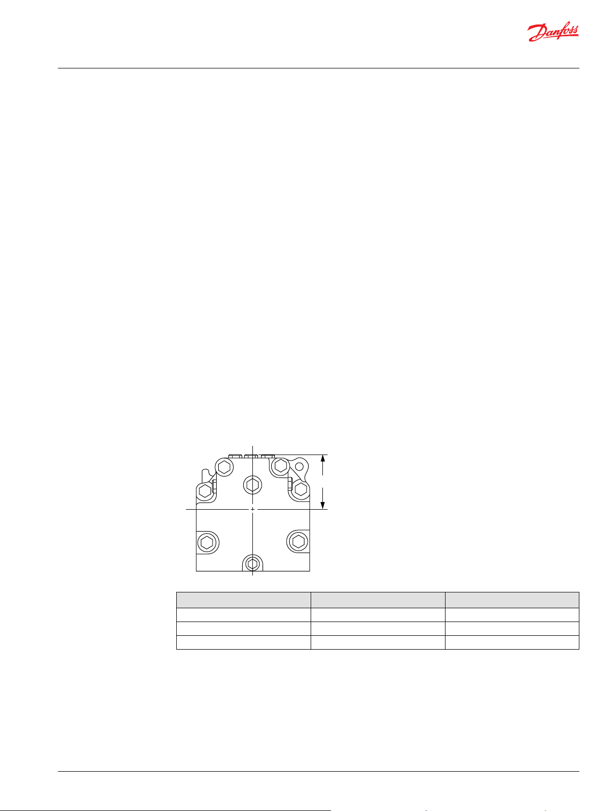
The new style charge relief plug protrudes from the motor end cap approximately .63” (16mm) farther
than the shimmed design. New dimensions from the center line to the top of the charge relief valve plug
are shown below.
Size Non-adjustable dimension (A) Adjustable dimension (A)
55cc 82.3 mm [3.24 in] 98.3 mm [3.87 in]
75cc 88.9 mm [3.50 in] 105 mm [4.13 in]
100cc 92.5 mm [3.64 in] 108.5 mm [4.27 in]
Models affected
All94-3xxx, 95-3xxx, and 96-3xxx fixed displacement motors
Series numbers
All 55cc motors (94-3xxx) will change at s/n A-89-38-xxxxx
All 75cc motors (95-3xxx) will change at s/n A-89-44-xxxxx
©
Danfoss | January 2020 AX00000094en-000204 | 61
Page 62
Parts Manual
Series 90 Motors, 100cc
Service bulletin
All 100cc motors (96-3xxx) will change at s/n A-90-20-xxxxx
Part numbers affected
Charge relief and loop flushing hardware for old vintage motors can be found in the Series 90 Parts
Manual (520L0890). The new part numbers are as follows:
New charge relief and loop flushing hardware
Item Part number Description Quantity
K90 9003575-0101 Nut 1
K10 8800488-1000 Plug assembly 1
K50 9004201-6200 O-ring 1
K70 8800476 Spring 1
K80 8800449 Poppet 1
K000 9005100-8700 Plug assembly 1
H10 8800550 Shuttle valve spool 1
H20 8800551 Washer 2
H30 364950 Spring 2
H40 9004201-3700 O-ring 2
H50 9005475-0097 Plug assembly 2
H10 8800552 Loop flushing spool,
defeated
1
New end caps
Part number Description
8000196 Twin port - 55 cc
8000197 Axial port - 55 cc
8100373 Twin port - 75 cc
8100374 Axial port - 75 cc
8200188 Twin port - 100 cc
8200189 Axial port - 100 cc
62 | © Danfoss | January 2020 AX00000094en-000204
Page 63
H20W
H30W
H40W
H50W
H68W
H66W
H64W
H62W
H60W
H20W
H30W
H50W
H40W
H10W
K000
H10N
Parts Manual
Series 90 Motors, 100cc
Service bulletin
Parts disposition
Non-interchangeable
©
Danfoss | January 2020 AX00000094en-000204 | 63
Page 64

Parts Manual
Series 90 Motors, 100cc
Service bulletin
SB-1998-007
Products affected
Series 90 55cc, 75cc, and 100cc fixed displacement motors, and 55cc and 75cc variable displacement
motors
Subject
Charge relief seat
Description
Danfoss has initiated a change to the end caps used on series 90 55cc, 75cc, and 100cc fixed
displacement motors, and the series 90 55cc and 75cc variable displacement motors.
Currently, the end caps used on these motors contain a pressed in insert, which serves as a seat for the
charge pressure relief valve assembly. The insert was originally introduced to provide a suitable wear
surface for the charge pressure relief valve poppet.
Since the original design, a number of changes to the charge pressure relief valve design have reduced
the severity of the wear characteristics between the poppet and relief seat. These changes have now
made it possible to remove the insert from the end cap assembly. The design of the motor end cap has
been modified in a manner that allows the charge relief poppet to seat directly against the casting
machined surface.
The removal of the insert was initially introduced with the series 90 130cc motors in 1995, and with this
change a more uniform product family is achieved.
To aid in identifying and tracking this change, Danfoss has released new end cap part numbers. The new
end cap is directly interchangeable with the previous end cap and with adjustable charge pressure relief
valve components. The previous end cap part numbers will no longer be available as service parts. Page 2
of this bulletin provides part number cross-reference information.
Models affected
All 94-3xxx, 943xxxx, 95-3xxx, 953xxxx, 96-3xxx, and 963xxxx fixed displacement motors.
All 94-4xxx, 944xxxx, 95-4xxx, 954xxxx variable displacement motors.
Serial numbers
Change became effective with s/n A-98-34-xxxxx and beyond.
64 | © Danfoss | January 2020 AX00000094en-000204
Page 65

Parts Manual
Series 90 Motors, 100cc
Service bulletin
Part numbers affected
Motor type Displacement Order code Porting Split flange
thread
Fixed 55 cc D Twin Metric 8000417 8000593
Fixed 55 cc 1 & 8 Twin English 8000196 8000594
Fixed 55 cc 3 & 7 Axial English 8000197 8000596
Variable 55 cc R Twin Metric 8000356 8000598
Variable 55 cc 1 & 8 Twin English 8000335 8000599
Fixed 75 cc D Twin Metric 8100576 8100731
Fixed 75 cc 1 & 8 Twin English 8100373 8100733
Fixed 75 cc 3 & 7 Axial English 8100374 8100734
Variable 75 cc 1 & 8 Twin English 8100442 8100737
Fixed 100 cc E Twin English 8200319 8200407
Fixed 100 cc 1 & 8 Twin English 8200188 8200408
Fixed 100 cc 3 & 7 Axial English 8200189 8200409
Prior to 98-34 Current
Parts disposition
Interchangeable
©
Danfoss | January 2020 AX00000094en-000204 | 65
Page 66

Parts Manual
Series 90 Motors, 100cc
Service bulletin
SB-1999-036
Products affected
Series 90 100cc fixed displacement motors
Subject
Motor housing change
Description
Danfoss has introduced a design change to the motor housings used on all series 90 100cc fixed
displacement motors. The housing strength has been increased in the area of the casting ribs, by
increasing the size of the rib. This change will reduce the potential for cracking the rib of the housing
when tightening the two shorter end cap bolts.
To assist in identifying this change, Danfoss has released a new housing part number. The new housing is
completely interchangeable with the previous housing. The previous housing has been obsoleted and is
no longer available
Models affected
All 96-3xxx, and 963xxxx fixed displacement motors.
Serial numbers
Danfoss Ames Production - Effective on motor serial number A-99-44-xxxxx.
Danfoss Neumunster Production - Effective on motor serial number N-99-45-xxxxx.
Danfoss Shanghai Production- effective during the fourth quarter of 2000.
Part numbers affected
Description Previous Housing New Housing
motor housing - MF 8200230 8200447
66 | © Danfoss | January 2020 AX00000094en-000204
Page 67

Parts Manual
Series 90 Motors, 100cc
Service bulletin
Parts disposition
Interchangeable
©
Danfoss | January 2020 AX00000094en-000204 | 67
Page 68

Spring seat
Spring
Spring assembly
Old design New design
Parts Manual
Series 90 Motors, 100cc
Service bulletin
SB-2000-047
Products affected
Series 90 42cc, 55cc, 75cc, and 100cc fixed displacement motors, and 55cc and 75cc variable
displacement motors
Subject
Loop flushing spring and spring seat change
Description
As a product improvement, Danfoss has changed the design of the spring and spring seat for the series
90 42cc, 55cc, 75cc, and 100cc fixed and variable displacement motors. The old design used a separate
spring and spring seat. The new design incorporates the two parts into a one piece assembly. This makes
the assembly of the spring and spring seat onto the spool much easier than the previous design.
Since the new spring assembly has a high spring rate than the previous spring, this is an interchangeable
change only if both springs and spring seats are replaced at the same time. Danfoss has issued a new part
number for the spring assembly. The previous spring seat and spring remain valid service parts since they
are used on other Danfoss products.
Models affected
All 93-3xxx, 933xxxx, 94-3xxx, 943xxxx, 95-3xxx, 953xxxx, 96-3xxx, and 963xxxx fixed displacement
motors with loop flushing options of A, B, or C.
All 94-4xxx, 944xxxx, 95-4xxx, and 954xxxx variable displacement motors with loop flushing options of A,
B, or C.
Serial numbers
Danfoss Ames, IA production - Change effective at serial number A-02-03-xxxxx.
Danfoss Neumunster, Germany production - Change effective at serial number N-01-08-xxxxx..
Part numbers affected
Previous spring seat Previous spring New spring assembly
8800551 4350286 513596
Parts disposition
Interchangeable
68 | © Danfoss | January 2020 AX00000094en-000204
Page 69

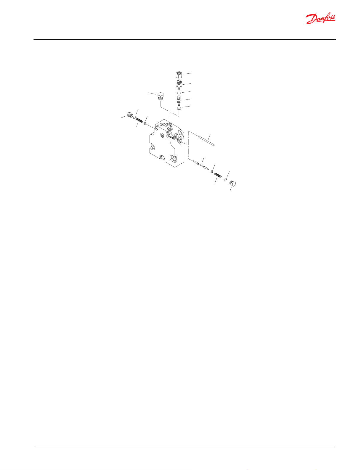
For both twin and axial
port end cap
For axial port
end cap
For twin port
end cap
Parts Manual
Series 90 Motors, 100cc
Service bulletin
SB-2001-011
Products affected
Series 90 55cc, 75cc, and 100cc fixed displacement motors
Subject
Change to end cap gasket material
Description
The end cap gasket material has changed. Danfoss has issued new end cap gasket part numbers. The
previous part numbers are obsolete. They are no longer available for service.
Models affected
All 94-3xxx, 943xxxx, 95-3xxx, 953xxxx, 96-3xxx, and 963xxxx fixed displacement motors.
Serial numbers
Danfoss Ames, IA production - Change effective at s/n A-01-19-xxxxx.
Danfoss Neumunster, Germany production - Change effective at s/n N-01-19-xxxxx..
Part numbers affected
Frame size Mounting flange (end cap
porting)
55 cc SAE (all), cartridge (axial) 8000167 8000721
55 cc Cartridge (twin) 8000603 8000720
75 cc SAE (all), cartridge (axial) 8100311 8100875
75 cc Cartridge (twin) 8100749 8100874
100 cc SAE (all) 8200102 8200511
Previous end cap gasket New end cap gasket
Parts disposition
Interchangeable
©
Danfoss | January 2020 AX00000094en-000204 | 69
Page 70

Parts Manual
Series 90 Motors, 100cc
Service bulletin
SB-2002-048
Products affected
Series 90 55cc pumps and motors, and 75 - 100 cc motors
Subject
Consolidation of valve plate part numbers
Description
Danfoss has consolidated the part numbers for some of the series 90 pump and motor valve plates. Our
plant in Germany has been producing the valve plates for series 90 pumps and motors since August 7,
2001. The U.S. plant has its part number for these valve plates as the German plant has its part number.
The U.S. plant will now use the German part number. This obsoletes the U.S. part numbers. Since the
parts are the same, the part number are interchangeable.
Models affected
All series 90 75 cc pumps and motors, 75 cc motors, and 100 cc motors.
Serial numbers
This change became effective at serial number A-02-46-xxxxx.
Part numbers affected
Description Old part number New part number
Valve plate, 75 cc pump 8000071 314427
Valve plate, 75 cc motor 8000132 329748
Valve plate, 75 cc motor 8100278 323766
Valve plate, 100 cc motor 8200134 324137
Parts disposition
Non-interchangeable
70 | © Danfoss | January 2020 AX00000094en-000204
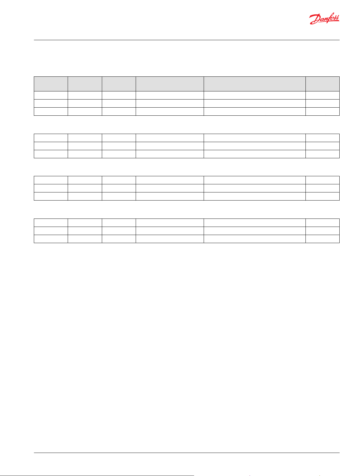
Page 71

G96
G90
G95
Parts Manual
Series 90 Motors, 100cc
Service bulletin
SB-2003-010
Products affected
Series 90 100cc fixed displacement motors
Subject
Housing change to accept long screws
Description
Danfoss has changed the housing used in series 90 100 cc fixed motors. Material was added at the area of
the two shorter end cap mounting screws (G95). The hole for these screws is now deeper to accept the
longer screw (G90) that is used for the other four large end cap mounting screws. The six larger screws
will have the same stretch and therefore the same clamping force for the gasket sealing area. The smaller
end cap mounting screw (G96) remains the same. The “old” housing and the short screws will become
obsolete and no longer available for service.
Models affected
All series 90 100 cc fixed displacement motors
Serial numbers
US production started on 5 April 2004 (serial number A-04-15-xxxxx)
Part numbers affected
Description Old part number New part number
Housing 8200447 8200509
Screw (G95) 9007210-1609 9007210-1617
Parts disposition
Non-interchangeable
©
Danfoss | January 2020 AX00000094en-000204 | 71
Page 72

Danfoss
Power Solutions GmbH & Co. OHG
Krokamp 35
D-24539 Neumünster, Germany
Phone: +49 4321 871 0
Danfoss
Power Solutions ApS
Nordborgvej 81
DK-6430 Nordborg, Denmark
Phone: +45 7488 2222
Danfoss
Power Solutions (US) Company
2800 East 13th Street
Ames, IA 50010, USA
Phone: +1 515 239 6000
Danfoss
Power Solutions Trading
(Shanghai) Co., Ltd.
Building #22, No. 1000 Jin Hai Rd
Jin Qiao, Pudong New District
Shanghai, China 201206
Phone: +86 21 2080 6201
Products we offer:
Hydro-Gear
www.hydro-gear.com
Daikin-Sauer-Danfoss
www.daikin-sauer-danfoss.com
DCV directional control
•
valves
Electric converters
•
Electric machines
•
Electric motors
•
Gear motors
•
Gear pumps
•
Hydrostatic motors
•
Hydrostatic pumps
•
Orbital motors
•
PLUS+1® controllers
•
PLUS+1® displays
•
PLUS+1® joysticks and
•
pedals
PLUS+1® operator
•
interfaces
PLUS+1® sensors
•
PLUS+1® software
•
PLUS+1® software services,
•
support and training
Position controls and
•
sensors
PVG proportional valves
•
Steering components and
•
systems
Telematics
•
Danfoss Power Solutions is a global manufacturer and supplier of high-quality hydraulic and
electric components. We specialize in providing state-of-the-art technology and solutions
that excel in the harsh operating conditions of the mobile off-highway market as well as the
marine sector. Building on our extensive applications expertise, we work closely with you to
ensure exceptional performance for a broad range of applications. We help you and other
customers around the world speed up system development, reduce costs and bring vehicles
and vessels to market faster.
Danfoss Power Solutions – your strongest partner in mobile hydraulics and mobile
electrification.
Go to www.danfoss.com for further product information.
We offer you expert worldwide support for ensuring the best possible solutions for
outstanding performance. And with an extensive network of Global Service Partners, we also
provide you with comprehensive global service for all of our components.
Local address:
Danfoss can accept no responsibility for possible errors in catalogues, brochures and other printed material. Danfoss reserves the right to alter its products without notice. This also applies to products
already on order provided that such alterations can be made without subsequent changes being necessary in specifications already agreed.
All trademarks in this material are property of the respective companies. Danfoss and the Danfoss logotype are trademarks of Danfoss A/S. All rights reserved.
©
Danfoss | January 2020 AX00000094en-000204
 Loading...