

Page 1

KOLLMORGEN
www.DanaherMotion.com
Solutions by
DANAHER
MOTION
SERVOSTAR® CD
VarCom Reference Guide
M-SS-017-04
Rev. M
Firmware Version 6.3.3 and before
Page 2
Version History
Revision Date Description of Revision
1 3/31/99 Transition from Quick Ref format to VarCom .PDF doc
2 12/20/99 Addition of Variables
3 1/20/00 Correction of HOMESTATE variable, added AUTONULL
4 06/30/00 Added HSAVE and ZPOS. Removed documentation
5 03/30/01 Updated commands for firmware 3.6.
6 06/30/01 Added information for firmware 4.1 and corrected errors.
7 09/12/01 Added information for firmware version 4.1.8.
8 03/01/02 Updated HOMETYPE, INxMODE, and PFBOFF
9 06/14/02 Added information on slow moves
10 12/16/02 Updated ISCALE , OPMODE, and O1MODE
11 04/18/03 Added Series 5 UCB2 digital board commands
L 09/07/04 Separated SERVOSTAR-S from SERVOSTAR-CD,
M 09/16/05 Updated MOTORTYPE
history.
updated corporate identity, and added Series 5
functionality.
© Copyright 2000 - 2005 Danaher Motion - All rights reserved
Printed in the United States of America.
DANAHER MOTION is a registered trademark of Danaher Corporation. Danaher
Motion makes every attempt to ensure accuracy and reliability of the
specifications in this publication. Specifications are subject to change without
notice. Danaher Motion provides this information "AS IS" and disclaims all
warranties, express or implied, including, but not limited to, implied warranties of
merchantability and fitness for a particular purpose. It is the responsibility of the
product user to determine the suitability of this product for a specific application.
Warning Alerts users to potential physical danger or harm.
Failure to follow warning notices could result in personal injury
or death.
Caution Directs attention to general precautions, which if not
followed, could result in personal injury and/or equipment
damage.
Note Highlights information critical to your understanding or
use of the product.
Page 3

Danaher Motion 09/05 Table of Contents
Table of Contents
1 Commands and Variables by Function................................................1
1. 1 Analog Input-Related.................................................................1
1. 2 Communications..............................................................................1
1. 3 Configurable I/O..............................................................................1
1. 4 Current Variables And Commands..................................................1
1. 5 Drive And Motor Status ...................................................................1
1. 6 Drive Configuration And Modes.......................................................2
1. 7 Drive Enabling And Disabling..........................................................2
1. 8 Drive Parameters ............................................................................2
1. 9 Feedback Related ...........................................................................2
1. 10 Gearing-Related Paramenters.....................................................2
1. 11 Loop Compensation And Gains...................................................3
1. 12 Motion Control Parameters..........................................................3
1. 13 Motor Variables And Commands.................................................3
1. 14 Position Variables And Commands.............................................4
1. 15 Read And Write Switch Variables................................................4
1. 16 Read And Write Switch Mode Variables......................................4
1. 17 Read And Write Variables...........................................................5
1. 18 Read-Only Switch Mode Variables..............................................5
1. 19 Read-Only Switch Variables........................................................5
1. 20 Read-Only Variables...................................................................6
1. 21 Variable Recording And Playing..................................................6
1. 22 Variable Setting And Clearing......................................................6
1. 23 Velocity Variables And Commands .............................................6
2 VARIABLE AND COMMAND LIST..........................................................7
2. 1 Format.............................................................................................7
2.1.1. Command............................................................................................. 7
2.1.2. Variable................................................................................................ 7
2. 2 Variable And Command Set............................................................9
ACC ........................................................................................................ 9
ACKMODE...................................................................................................... 9
ACTFAULT ..................................................................................................... 9
ACTIVE ...................................................................................................... 10
ADDR ...................................................................................................... 10
ANDB ...................................................................................................... 10
ANDG ...................................................................................................... 10
ANIN ...................................................................................................... 11
ANLPFHZ...................................................................................................... 11
ANOFF ......................................................................................................11
ANOUT ......................................................................................................11
ANZERO ...................................................................................................... 12
AUTOHOME................................................................................................. 12
AUTONULL...................................................................................................12
AVGTIME 13
BW ...................................................................................................... 13
VarCom Reference M-SS-017-04 Rev M i
Page 4

Table of Contents 09/05 Danaher Motion
CCWLIM ......................................................................................................13
CLREEPROM ............................................................................................... 14
COMPFILT....................................................................................................14
COMPMODE................................................................................................. 14
CONFIG ......................................................................................................15
CONVERT.....................................................................................................15
CWLIM ......................................................................................................15
DEC ......................................................................................................15
DECSTOP.....................................................................................................16
DICONT ......................................................................................................16
DIP ......................................................................................................16
DIPEAK ......................................................................................................17
DIPEN ......................................................................................................17
DIR ......................................................................................................17
DIS ......................................................................................................18
DISSPEED....................................................................................................19
DISTIME ......................................................................................................19
DIVISIONS....................................................................................................19
DRIVEOK......................................................................................................19
DUMP ......................................................................................................20
DUALFB ......................................................................................................20
ECHO ......................................................................................................20
EN ......................................................................................................20
ENCINIT ......................................................................................................21
ENCINITST...................................................................................................21
ENCOUT ...................................................................................................... 21
ENCOUTMOD...............................................................................................22
ENCOUTO....................................................................................................22
ENCSTART................................................................................................... 22
ERR ......................................................................................................23
FILTMODE.................................................................................................... 23
FLTCLR ......................................................................................................23
FLTHIST ......................................................................................................23
FOLD ......................................................................................................24
FOLDMODE..................................................................................................24
FOLDTIME.................................................................................................... 24
GEAR ......................................................................................................24
GEARI ......................................................................................................25
GEARMODE.................................................................................................25
GEARO ......................................................................................................26
GET ......................................................................................................26
GETMODE.................................................................................................... 26
GP ......................................................................................................27
GPAFR ......................................................................................................27
GPAFR2 ......................................................................................................27
GPD ......................................................................................................27
GPI ......................................................................................................28
GPISATIN ..................................................................................................... 28
GPISATOUT ................................................................................................. 28
GPVFR ......................................................................................................28
GV ......................................................................................................29
GVI ......................................................................................................29
HALLS ......................................................................................................29
HCMODE ......................................................................................................29
ii M-SS-017-04 Rev. M VarCom Reference
Page 5

Danaher Motion 09/05 Table of Contents
HC1 ...................................................................................................... 30
HC2 ...................................................................................................... 30
HC3 ...................................................................................................... 31
HOLD ...................................................................................................... 31
HOMESPD.................................................................................................... 31
HOMESTATE................................................................................................ 31
HOMETYPE.................................................................................................. 32
HSAVE ...................................................................................................... 33
HWPOS ...................................................................................................... 33
I ...................................................................................................... 34
IA ...................................................................................................... 34
IAOFF ...................................................................................................... 34
IC ...................................................................................................... 34
ICOFF ...................................................................................................... 34
ICMD ......................................................................................................35
ICONT ...................................................................................................... 35
IENCSTART.................................................................................................. 35
IFRIC ...................................................................................................... 35
IGRAV ...................................................................................................... 35
ILIM ......................................................................................................36
ILIM2 ......................................................................................................36
ILSBMODE ................................................................................................... 36
IMAX ......................................................................................................36
IN ...................................................................................................... 37
IN1 ...................................................................................................... 37
IN1MODE...................................................................................................... 37
IN2 ...................................................................................................... 39
IN2MODE...................................................................................................... 39
IN3 ...................................................................................................... 41
IN3MODE...................................................................................................... 41
IN4 ...................................................................................................... 43
IN4MODE...................................................................................................... 43
IN5 ...................................................................................................... 44
IN5MODE...................................................................................................... 44
IN6 ...................................................................................................... 45
IN6MODE...................................................................................................... 45
INITMODE .................................................................................................... 46
ININV4 ...................................................................................................... 46
ININV5 ...................................................................................................... 47
ININV6 ...................................................................................................... 47
INDEXPOS ................................................................................................... 47
ININV1 ...................................................................................................... 47
ININV2 ...................................................................................................... 47
ININV3 ...................................................................................................... 48
INITGAIN ...................................................................................................... 48
INITMODE .................................................................................................... 48
INPOS ...................................................................................................... 48
ISCALE ...................................................................................................... 49
ISTOP ...................................................................................................... 49
IZERO ...................................................................................................... 49
J ...................................................................................................... 50
K ...................................................................................................... 50
KV ...................................................................................................... 50
KVFR ...................................................................................................... 50
VarCom Reference M-SS-017-04 Rev M iii
Page 6

Table of Contents 09/05 Danaher Motion
KVI ......................................................................................................51
LIMDIS ......................................................................................................51
LIST ......................................................................................................51
LMJR ......................................................................................................51
LOAD ......................................................................................................51
LPFHZ1 ......................................................................................................52
LPFHZ2 ......................................................................................................52
MA ......................................................................................................52
MAPOS ......................................................................................................53
MASPEED.....................................................................................................53
MBEMF ......................................................................................................53
MBEMFCOMP .............................................................................................. 54
MENCOFF .................................................................................................... 54
MENCRES....................................................................................................54
MENCTYPE..................................................................................................55
MFBDIR ......................................................................................................56
MFOLD ......................................................................................................56
MFOLDD ...................................................................................................... 57
MFOLDDIS....................................................................................................57
MFOLDR ...................................................................................................... 57
MFOLDT ......................................................................................................57
MH ......................................................................................................58
MHINVA ......................................................................................................59
MHINVB ......................................................................................................59
MHINVC ......................................................................................................59
MI ......................................................................................................59
MICONT ......................................................................................................60
MIDIST0 ......................................................................................................60
MIDIST1 ......................................................................................................61
MIDIST2 ......................................................................................................61
MIDIST3 ......................................................................................................61
MIPEAK ......................................................................................................62
MISPEED0....................................................................................................62
MISPEED1....................................................................................................63
MISPEED2....................................................................................................63
MISPEED3....................................................................................................64
MJ ......................................................................................................65
MLGAINC......................................................................................................65
MLGAINP 65
MLGAINZ ......................................................................................................66
MLIST ......................................................................................................66
MODMODE................................................................................................... 66
MOTOR ......................................................................................................67
MOTORTYPE ............................................................................................... 67
MPHASE ...................................................................................................... 67
MPITCH ......................................................................................................67
MPOLES ...................................................................................................... 68
MRESPOLES................................................................................................ 68
MSG ......................................................................................................68
MSININT ......................................................................................................69
MSINFRQ...................................................................................................... 69
MSPEED ...................................................................................................... 69
MTANGLC.....................................................................................................69
iv M-SS-017-04 Rev. M VarCom Reference
.................................................................................................66 MLMIN .....
Page 7

Danaher Motion 09/05 Table of Contents
MTANGLP..................................................................................................... 70
MVANGLF..................................................................................................... 70
MVANGLH.................................................................................................... 70
NOTCHBW ................................................................................................... 70
NOTCHHZ .................................................................................................... 71
O1 ...................................................................................................... 71
O1MODE UCB1 CD Series 2 ....................................................................... 71
O1MODE UCB2 CD Series 5 ....................................................................... 72
O1RST ...................................................................................................... 73
O1TRIG ...................................................................................................... 73
OPMODE ...................................................................................................... 74
PCMD ......................................................................................................74
PCMDMODE................................................................................................. 74
PE ...................................................................................................... 75
PEINPOS 75
PEMAX ......................................................................................................75
PEXT ...................................................................................................... 75
PEXTHW ...................................................................................................... 75
................................................................................................. 76 PEXTOFF....
PFB ...................................................................................................... 76
PFBOFF ...................................................................................................... 76
PLIM ......................................................................................................76
......................................................................................................PMAX 77
PMIN ...................................................................................................... 77
PRD ......................................................................................................77
MODEPROF ................................................................................................. 77
PROFSCRV.................................................................................................. 78
PT PROM ...................................................................................................... 78
APROT YR ..................................................................................................... 78
PSCALE ...................................................................................................... 79
RDRES ...................................................................................................... 79
READY ...................................................................................................... 79
RECDONE.................................................................................................... 79
RECING ...................................................................................................... 80
RECOFF ...................................................................................................... 80
RECORD ......................................................................................................80
RECRDY ...................................................................................................... 81
RECTRIG 81
REFRESH..................................................................................................... 83
RELAY ...................................................................................................... 83
RELAYMODE ............................................................................................... 83
................................................................................................. 83 REMOTE .....
RESBW ......................................................................................................84
RSTVAR ...................................................................................................... 84
S ......................................................................................................85
SAVE ...................................................................................................... 85
SERIALNO.................................................................................................... 85
SININIT ...................................................................................................... 85
SININTOUT................................................................................................... 85
SININITST..................................................................................................... 86
SINPARAM................................................................................................... 86
STAT ...................................................................................................... 87
STATUS ...................................................................................................... 87
STATUS2...................................................................................................... 89
VarCom Reference M-SS-017-04 Rev M v
Page 8

Table of Contents 09/05 Danaher Motion
STATUS2......................................................................................................91
STEP ......................................................................................................92
STOP ...................................................................................................... 93
STOPMODE..................................................................................................93
STOPPED.....................................................................................................94
SWEN ...................................................................................................... 94
T ......................................................................................................94
TESTLED
TF ......................................................................................................95
THERM ......................................................................................................95
THERMODE..................................................................................................95
THERMTIME.................................................................................................95
THERMTYPE................................................................................................96
TUNE ...................................................................................................... 96
UNITS ...................................................................................................... 97
UVMODE ......................................................................................................98
UVRECOVER ............................................................................................... 98
V ......................................................................................................98
VBUS ......................................................................................................99
VCMD ......................................................................................................99
VD ...................................................................................................... 99
VE ....................................................................................................100
VEXT ....................................................................................................100
VF .................................................................................................... 100
VFI ....................................................................................................101
VH .................................................................................................... 101
VLIM ....................................................................................................101
VMAX ....................................................................................................102
VOSPDENS................................................................................................102
VR .................................................................................................... 102
VSCAL .................................................................................................... 103
XENCD ....................................................................................................103
XENCDIR....................................................................................................103
XENCRES (UCB1 Series 2)........................................................................103
XENCRES (UCB2 Series 5)........................................................................104
ZERO ....................................................................................................104
ZPOS .................................................................................................... 104
......................................................................................................94
N TRU ......................................................................................................96
UVTIME ...................................................................................................... 98
R VE ....................................................................................................100
PDVOS ....................................................................................................102
E
IR
vi M-SS-017-04 Rev. M VarCom Reference
Page 9
Danaher Motion 09/05 Commands and Variables by Function
1 COMMANDS AND VARIABLES BY
FUNCTION
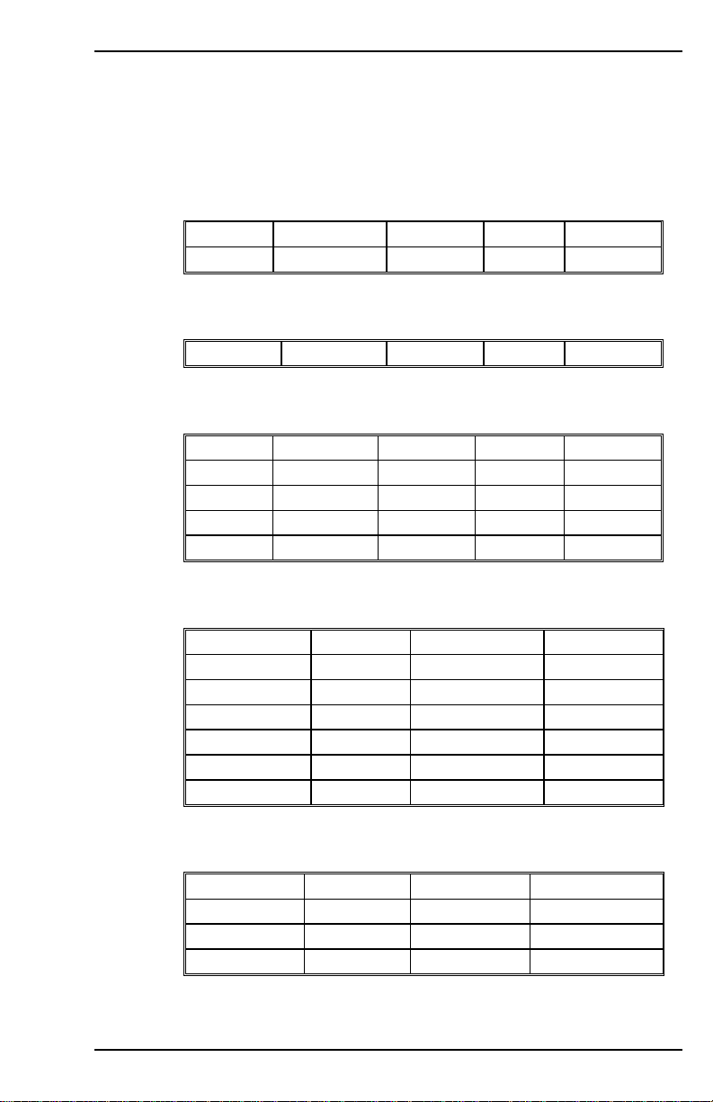
1. 1
ANALOG INPUT-RELATED
ANDB ANDG ANIN ANOFF ANZERO
GEARI GEARO ISCALE PMIN VSCALE
1. 2 COMMUNICATIONS
ACKMODE ADDR ECHO MSG PROMPT
1. 3 CONFIGURABLE I/O
ANOUT ENCOUT ENCOUTO IN IN1
IN1MODE IN2 IN2MODE IN3 IN3MODE
IN4 IN4MODE IN5 IN5MODE IN6
IN6MODE O1 O1MODE O1RST O1TRIG
MSINFRQ SININTOUT
1. 4 CURRENT VARIABLES AND COMMANDS
CONFIG DICONT DIPEAK FOLD
FOLDMODE FOLDTIME I IA
IC ICMD ICONT IENCSTART
IFRIC IGRAV ILIM ILIM2
IMAX ISCALE ISTOP IZERO
MFOLD MFOLDD MFOLDDIS MFOLDR
MFOLDT MICONT MIPEAK T
1. 5 DRIVE AND MOTOR STATUS
ACTIVE CCWLIM CWLIM DIP
ERR FLTCLR FLTHIST DRIVEOK
READY RELAY SERIALNO STAT
STATUS THERM TRUN VER
VarCom Reference M-SS-017-04 Rev. M 1
Page 10
Commands and Variables by Function 09/05 Danaher Motion
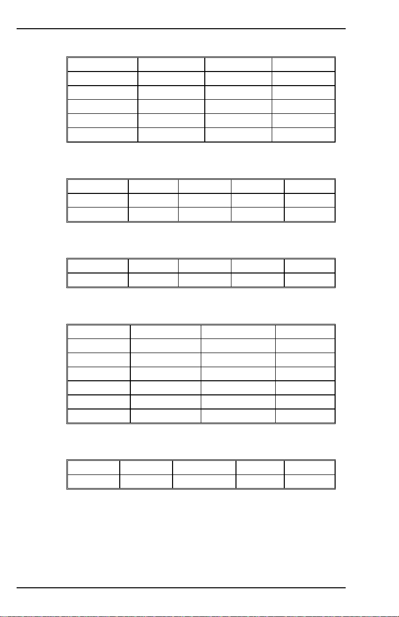
1. 6 DRIVE CONFIGURATION AND MODES
ACTFAULT COMPMODE DIP DIR
FILTMODE GEAR GEARI GEARMODE
GEARO HOLD LIMDIS OPMODE
PCMDMODE PROFMODE RELAYMODE STOPMODE
THERMODE THERMTIME THERMTYPE UNITS
UVMODE UVRECOVER UVTIME ZERO
1. 7 DRIVE ENABLING AND DISABLING
ACTIVE DIPEN DRIVEOK DIS EN
K READY REMOTE S STOP
SWEN
1. 8 DRIVE PARAMETERS
DICONT DIPEAK ERR FLTCLR FLTHIST
VBUS
1. 9 FEEDBACK RELATED
DUALFB ENCINIT ENCINITST ENCOUT
ENCOUTO ENCSTART HALLS HWPOS
IENCSTART MENCOFF MENCRES MENCTYPE
MFBDIR MHINVA MHINVB MHINVC
MPHASE MRESPOLES MSINFRQ MSININT
PFB PFBOFF PRD RDRES
RESBW SINPARAM STAT XENCRES
1. 10 GEARING-RELATED PARAMENTERS
GEAR GEARI GEARMODE GEARO PCMD
PE PEXT PEXTOFF
2 M-SS-017-04 Rev. M VarCom Reference
Page 11
Danaher Motion 09/05 Commands and Variables by Function
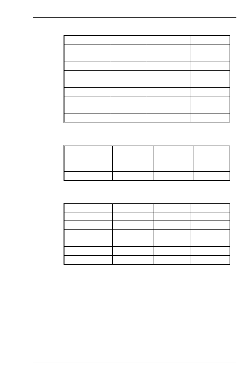
1. 11 LOOP COMPENSATION AND GAINS
ANDG BW COMPFILT COMPMODE
FILTMODE GP GPAFR GPD
GPI GPISATIN GPISATOUT GPVFR
GV GVI KV KVI
KVFR LMJR LPFHZ1 LPFHZ2
MJ MLGAINP MLGAINZ MTANGLC
MTANGLP MVANGLF MVANGLH NOTCHBW
NOTCHHZ REFRESH TF TUNE
VD VEXT VF VH
VR
1. 12 MOTION CONTROL PARAMETERS
ACC CCWLIM CWLIM DEC
DECSTOP DIR DISSPEED DISTIME
INPOS LIMDIS OPMODE PEINPOS
PROFMODE PROFSCRV STOPMODE
1. 13 MOTOR VARIABLES AND COMMANDS
MBEMF MBEMFCOMP MENCOFF MENCRES
MENCTYPE MHINVA MHINVB MHINVC
MICONT MIPEAK MJ MLGAINC
MLGAINP MLGAINZ MLIST MLMIN
MOTOR MOTORTYPE MPHASE MPITCH
MPOLES MRESPOLES MSININT MSPEED
MTANGLC MTANGLP MVANGLF MVANGLH
VarCom Reference M-SS-017-04 Rev. M 3
Page 12
Commands and Variables by Function 09/05 Danaher Motion
1. 14 POSITION VARIABLES AND COMMANDS
DUALFB HOMESPD HOMESTATE HOMETYPE
HWPOS INPOS MA MAPOS
MASPEED MH MI MIDIST0
MIDIST1 MIDIST2 MIDIST3 MISPEED0
MISPEED1 MISPEED2 MISPEED3 PCMD
PCMDMODE PE PEINPOS PEMAX
PFB PLIM PMAX PMIN
PRD PSCALE STOPPED
1. 15 READ AND WRITE SWITCH VARIABLES
ACTFAULT COMPFILT DIR ECHO
GEAR HOLD LIMDIS MFOLDDIS
MHINVA MHINVB MHINVC MSG
O1 PCMDMODE PLIM PROMPT
RELAYMODE THERMTYPE UNITS UVRECOVER
ZERO
1. 16 READ AND WRITE SWITCH MODE VARIABLES
ACKMODE ANOUT AVGTIME COMPMODE
ENCOUT ENCOUTO FILTMODE FOLDMODE
GEARMODE GETMODE HOMETYPE IN1MODE
IN2MODE IN3MODE MENCTYPE MFBDIR
MOTORTYPE MPOLES MRESPOLES MSINFRQ
O1MODE OPMODE PCMDMODE PROFMODE
STAT STOPMODE THERMODE UVMODE
4 M-SS-017-04 Rev. M VarCom Reference
Page 13
Danaher Motion 09/05 Commands and Variables by Function
1. 17 READ AND WRITE VARIABLES
ACC ANDB ANDG ANOFF
BW DEC DECSTOP DISSPEED
DISTIME FOLDTIME GEAR GEARI
GEARO GP GPAFR GPAFR2
GPD GPI GPISATIN GPISATOUT
GPVFR GV GVI HOMESPD
ICONT IENCSTART IFRIC IGRAV
ILIM ILIM2 IN ISCALE
ISTOP IZERO KV KVFR
KVI LMJR LPFHZ1 LPFHZ2
MAPOS MASPEED MBEMF MBEMFCOMP
MENCOFF MENCRES MFOLDD MFOLDR
MFOLDT MICONT MIDIST0 MIDIST1
MIDIST2 MIDIST3 MIPEAK MISPEED0
MISPEED1 MISPEED2 MISPEED3 MJ
MLGAINP MLGAINZ MLMIN MOTOR
MPHASE MPITCH MSININT MSPEED
MTANGLC MTANGLP MVANGLF MVANGLH
NOTCHBW O1RST O1TRIG PEINPOS
PEMAX PEXTOFF PFBOFF PMAX
PMIN PROFSCRV PSCALE RECTRIG
TF THERMTIME UVTIME VBUS
VD VF VH VLIM
VOSPD VR VSCALE XENCRES
1. 18 READ-ONLY SWITCH MODE VARIABLES
DIP ENCINITST HALLS HOMESTATE ILSBMODE
IN RDRES
1. 19 READ-ONLY SWITCH VARIABLES
CCWLIM CWLIM DIPEN DRIVEOK FOLD
IN1 IN2 IN3 MFOLD READY
RECDONE RECING RECRDY RELAY REMOTE
STOPPED SWEN THERM
VarCom Reference M-SS-017-04 Rev. M 5
Page 14
Commands and Variables by Function 09/05 Danaher Motion
1. 20 READ-ONLY VARIABLES
ADDR ANIN DICONT DIPEAK HWPOS
I IA IC ICMD IMAX
PCMD PE PEXT PFB PRD
STAT STATUS TRUN V VCMD
VE VER VEXT VMAX
1. 21 VARIABLE RECORDING AND PLAYING
AVGTIME GET GETMODE RECDONE RECING
RECOFF RECORD RECRDY RECTRIG STATUS
1. 22 VARIABLE SETTING AND CLEARING
CLREEPROM DUMP LIST LOAD
MLIST RESBW SAVE
1. 23 VELOCITY VARIABLES AND COMMANDS
ACC DEC DECSTOP ILSBMODE J
MSPEED PROFSCRV S STOP V
VCMD VE VEXT VLIM VMAX
VOSPD VSCALE
6 M-SS-017-04 Rev. M VarCom Reference
Page 15

Danaher Motion 09/05 VARIABLE AND COMMAND LIST
2 VARIABLE AND COMMAND LIST
2. 1
FORMAT
The command and variable descriptions presented here are in
alphabetical order. Command and variable descriptions use
different formats, as described below. Section 2 contains
commands applicable to CD Series 2 and CD Series 5. Appendix B
continues with command variables applicable to CD Series 5 only.
2.1.1. COMMAND
This is the format of a command description.
Firmware Versions: Command Syntax:
Opmodes: Drive Status:
Firmware Versions: tells in what firmware versions the command
is implemented. To check your drive’s firmware version, use the
VER command.
Command Syntax: gives the exact syntax of the command. Any
optional or required parameters are also listed. If parameters are
used with the command, the units and ranges of those parameters
are given.
Opmodes: (0-4, 8) indicates in which operational modes
(opmodes) the command can be used
(see the description for the variable OPMODE).
Drive Status: (en, dis, or EN/DIS) indicates the drive state in which
the command can be used (en = enabled; dis = disabled; EN/DIS =
either).
2.1.2. VARIABLE
This is the format that a variable description will take.
Firmware Versions: Type:
Range:
Units: Default:
Opmodes: Drive Status:
EEPROM:
You can set variable values by typing in the name of the variable
followed by a new value for the variable, separated by an equals
sign or one or more spaces. Just typing in the name of a variable
without a new value will cause the SERVOSTAR to output the
current value of that variable to the serial port.
Firmware Versions: tells what firmware versions the variable is
implemented in. To check your drive’s firmware version, use the
VER command.
VarCom Reference M-SS-017-04 Rev. M 7
Page 16

VARIABLE AND COMMAND LIST 09/05 Danaher Motion
Type: switch variable, switch mode variable, (standard) variable, or
vector variable. Switch variables can be toggled between two
different states (0/1, on/off, etc.). Switch mode variables are state
variables used to select one of more than two states (for example,
opmode is a switch mode variable that selects one of 6 Opmodes:
0-4, 8). Standard variables are set to an integer value within a given
range.
Vector variables are special variables that are used for the
Advanced Pole Placement compensator (COMPMODE=3) and
require the use of the REFRESH command when changed.
All variables are classified as read-only (R) or read/write (R/W).
Range: defines the range of valid values for the variable.
Units: defines the units of the variable. Note that to get the final
value of the variable, including its units, you multiply its value by its
units. Example: the units of MICONT are “amps * 0.1.” If MICONT =
200, then its value is 200 * amps * 0.1 = 20 amps.
Default: defines the default value of the variable. If this field says
“motor data,” then the default value is entered from a motor data file
(using MOTIONLINK’s Motor Configuration Screen) or a motor data
sheet. Most variables are reset to their defaults by using the
RSTVAR command.
Opmodes: (0-4, 8) indicates in which operational modes
(opmodes) the variable is used (see the description for the variable
OPMODE). Most variables can be set in any opmode, but they only
have an effect in the opmodes listed here.
Drive Status: (en, dis, or EN/DIS) indicates the drive state in which
the command can be used (en = enabled; dis = disabled; EN/DIS =
either).
EEPROM: (Yes or no) specifies whether or not a variable can be
stored in non-volatile memory (EEPROM). If a variable is stored in
EEPROM, it is “remembered” by the SERVOSTAR when the drive
is powered down and back up. See the SAVE command for more
information.
8 M-SS-017-04 Rev. M VarCom Reference
Page 17

Danaher Motion 09/05 VARIABLE AND COMMAND LIST
2. 2 VARIABLE AND COMMAND SET
ACC
Sets the drive acceleration rate. This variable is only asserted when
linear ramp control is selected (PROFMODE = 1 and OPMODE = 0, 1,
4, or 8). For firmware versions (VER) prior to 3.1.0, the range of this
variable was 1 to 399,987.
Firmware Versions: All Default: 400,000
Range: 10 to 400,000 Drive Status: EN/DIS
Opmodes: 0, 1, 4, 8 Units: rotary: rpm / sec
Type: variable (R/W) EEPROM: Yes
linear: mm/sec/sec
ACKMODE
Sets the communication safety level of the drive. The range of value is 0
through 2.
0 = No safety procedures or error messages
1 = Drive responds with ACK or NAK after every message
2 = Same as 1 with an added Block Check Character (BCC or
checksum) attached to the end of every message
ACKMODE must be 0 for MOTIONLINK to function properly.
NOTE
Firmware Versions: All Type: switch mode (R/W)
Range: 0 - 2 Default: 400,000
Opmodes: All Drive Status: EN/DIS
EEPROM: Yes Units: N/A
ACTFAULT
Defines how to handle the DISABLE procedure when a fault occurs.
0 = disable the drive immediately
1 = follow an Active Disable procedure (similar to the “S” cmd. See also
DECSTOP, DISSPEED, DISTIME, and O1MODE=5)
The drive is always disabled immediately in the event of a
feedback loss fault to prevent the drive from running away.
VarCom Reference M-SS-017-04 Rev. M 9
NOTE
Firmware Versions: All Type: switch (R/W)
Range: 0, 1 Default: 0
Opmodes: All Drive Status: EN/DIS
Units: N/A EEPROM: Yes
Page 18

VARIABLE AND COMMAND LIST 09/05 Danaher Motion
ACTIVE
Displays if the drive is enabled and power is applied to the motor. This
flag is the overall readiness indicator of the drive.
0 = drive is inactive
1 = drive is active and ready to operate
Firmware Versions: All Type: switch (R)
Range: 0, 1 Default: N/A
Opmodes: All Drive Status: EN/DIS
Units: N/A EEPROM: No
ADDR
Displays the position of the drive address switches (switches 1-4 or 1-5,
depending upon firmware version) of the DIP switch located on the top
of the drive.
Firmware Versions: All Type: variable (R)
Range: 0 to 15 (firmware versions prior to 2.0.0)
0 to 31 (firmware versions 2.0.0 and later)
Default: hardware defined Drive Status: EN/DIS
Units: N/A
Opmodes: All
EEPROM: No
ANDB
Sets the dead band of the analog input signal. If the absolute value of
the analog input signal is less than this value, no analog command
signal is generated.
Firmware Versions: All Type: variable (R/W)
Range: 0 to 10,000 Default: 0
Opmodes: 1,3,8 Drive Status: EN/DIS
Units: mV EEPROM: No
ANDG
Enables the drive's dual gain algorithm. The dual gain algorithm
effectively increases the resolution of the command input from 14 to 15
bits under 4 V of input.
0 - No dual gain
1 - Dual gain hysteresis algorithm
2 - Dual gain linear combination algorithm
Firmware Versions: 2.1.0 and later Type: variable (R/W)
Range: 0 to 2 Default: 0
Opmodes: 1,3,8 Drive Status: EN/DIS
Units: N/A EEPROM: Yes
10 M-SS-017-04 Rev. M VarCom Reference
Page 19

Danaher Motion 09/05 VARIABLE AND COMMAND LIST
ANIN
Displays the analog input value after being filtered by ANOFF and
ANDB. The AVGTIME variable affects the time averaging of this
variable.
Firmware Versions: All Type: variable (R)
Range: -22,500 to 22,500 Default: N/A
Opmodes: All Drive Status: EN/DIS
Units: mV EEPROM: No
ANLPFHZ
Sets a filter rate (corner frequency) for the analog input filter. This is a
simple single pole filter that is always present. The filter rate adjusts
automatically as the analog input sampling rate changes for different
operational modes. A value of 10,000 = unity gain (no filter).
Firmware Versions: 2.1.0 and later Type: variable (R/W)
Range: 1 to 10,000 Default: 10,000
Opmodes: 1,3,8 Drive Status: EN/DIS
Units: Hz EEPROM: Yes
ANOFF
Sets the analog offset that is added to the analog input command to the
drive. This is used to compensate for the analog input signal (ANIN)
offset or drift.
Firmware Versions: All Type: variable (R/W)
Range: -10,000 to 10,000 Default: 0
Opmodes: 1,3,8 Drive Status: EN/DIS
Units: mV EEPROM: Yes
ANOUT
Sets the source for the analog output feature at user connector C3 pin
13.
0 - Tachometer (velocity feedback V) scaled identical to VSCALE
with an update rate of 250 µs.
1 - I monitor (equivalent current) scaled identical to ISCALE with an
update rate of 10 ms (this variable is calculated in background
loop).
2 - Velocity Error, VE, scaled identical to VSCALE with an update
rate of 250 µs.
3 - Torque Command Output Scaled to ISCALE with an update rate
of 500 µs.
4 – Reserved, no update rate.
5 - Position following error, PE, scaled to PSCALE with an update
rate of 500 µs.
6 - not used, with a minimum update rate of 500 µs.
7 - not used, with an update rate of 62.5 µs.
VarCom Reference M-SS-017-04 Rev. M 11
Page 20

VARIABLE AND COMMAND LIST 09/05 Danaher Motion
8 - Position feedback, PFB, scaled to PSCALE with an update rate
of 500 µs.
9 - Velocity controller output (before injecting PRB/HC), scaled to
VSCALE with an update rate of 250 µs.
Firmware Versions: 2.1.0 and later Type: switch mode (R/W)
Range: 0 to 5 Default: 0
Opmodes: All Drive Status: EN/DIS
Units: N/A EEPROM: Yes
ANZERO
Causes the drive to zero the analog offset. A sample of the motor
analog input command is averaged over 64 samples, and the value of
ANOFF is set to zero out the analog input command. This command
may need to be executed more than once to achieve zero offset, and
ANOFF will probably be modified.
Firmware Versions: All Command Syntax: ANZERO
Opmodes: All Drive Status: EN/DIS
AUTOHOME
Defines the homing behavior on power-up.
0 = No homing on power-up (default).
1 = Try to perform homing on power-up. Does not continue if the
homing cannot be executed.
2 = Try to perform homing on power-up. Continue trying until
homing process is executed.
Firmware Versions: 3.7.0 and later Opmodes: 8
Range: 0 to 2 Default: 0
EEPROM: Yes
AUTONULL
Automatic calibration of the current loop at drive enable.
AUTONULL = 1: The drive applies zero volts to the motor for 50 ms.
The motor must be at or near rest or the results can be
unpredictable.
AUTONULL = 0: The drive reads current after the drive has been
disabled. A series of reads over many seconds allows
the average reading to be calculated and used as
current sensor offset.
AUTONULL=2: Cancels all automatic nulling and allows the user to
manually adjust the offset using IAOFF and ICOFF.
All offsets pertain to IA and IC current sensors. The offsets, whether
calculated internally or set manullay can be querried with IAOFF and
ICOFF.
Firmware Versions: 3.4.2 EEPROM: Yes
Range: 0 (Old method)
1 (Zero on enable),
2 User Defined offsets with IAOFF and ICOFF
12 M-SS-017-04 Rev. M VarCom Reference
Default: 0
Page 21

Danaher Motion 09/05 VARIABLE AND COMMAND LIST
AVGTIME
Sets the variable averaging time period. This variable is expressed as
multiples of the servo update period (Ts), which is 500 µs. A value of 0
for AVGTIME causes requested variable values to be returned as
instantaneous values. AVGTIME affects the time averaging of ANIN, I,
ICMD, V, VCMD.
AVGTIME has no effect on variables that are sampled using
the RECORD command and MOTIONLINK’s PC Scope
NOTE
Firmware Versions: All Type: switch mode (R/W)
Range: 0, 2, 4, 8, 16, 32, or 64 Default: 0
Opmodes: All Drive Status: EN/DIS
Units: Ts (500 µs) EEPROM: Yes
Screen.
BW
Sets the desired velocity control loop bandwidth. This variable only
affects the system when using the Standard Pole Placement controller
in velocity mode (COMPMODE = 2 or 4 and OPMODE = 0 or 1). With
COMPMODE=2, BW is limited to 200 Hz; with COMPMODE=4, BW can
extend to 400 Hz.
COMPMODE=4 is only available in firmware versions 2.1.0
and later.
NOTE
Firmware Versions: All Units: Hz
Range: 10 to 200 (COMPMODE=2)
10 to 400 (COMPMODE=4)
Type: variable (R/W) Drive Status: EN/DIS
Default: 20
Opmodes: 0,1,4,8
EEPROM: Yes
CCWLIM
Displays the state of the external counter clockwise (CCW) limit switch
input.
0 = switch closed, CCW limit not reached
1 = switch open, CCW limit reached
Firmware Versions: All Type: switch(R)
Range: 0, 1 Default: hardware defined
Opmodes: All Drive Status: EN/DIS
Units: N/A EEPROM: No
VarCom Reference M-SS-017-04 Rev. M 13
Page 22
VARIABLE AND COMMAND LIST 09/05 Danaher Motion
CLREEPROM
Clears the non-volatile memory (EEPROM) in the drive. The drive null’s
the EEPROM and recovers from a NVRAM error and assumes a nocomp state. A complete drive configuration procedure then has to be
initiated before resuming drive operation. This command is the only
method of resetting the run time clock.
Firmware Versions: All Command Syntax: CLREEPROM
Opmodes: All Drive Status: DIS
COMPFILT
COMPFILT is a switch variable that enables and disables a 400 Hz low
pass filter in the velocity feedback loop. The filter will automatically be
disabled if COMPMODE = 4. COMPFILT retains its value regardless of
whether the COMPMODE setting is enabling and disabling the filter.
Firmware Versions: 2.1.0 and later Type: switch(R/W)
Range: 0 (OFF), 1 (ON) Default: 1
Opmodes: 0,1,4,8 Drive Status: DIS
Units: N/A EEPROM: No
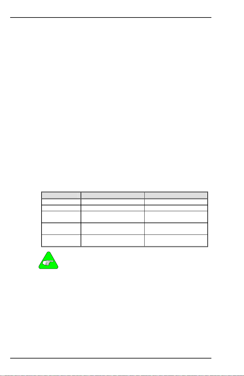
COMPMODE
Sets the velocity controller type for OPMODE 0 or 1 according to the
following table.
COMPMODE Controller Type Loop Variables
0 PI GV, GVI
1 PDFF KV, KVI, KVFR
2 Standard Pole Placement
3 Advanced Pole
4 Standard Pole Placement
COMPMODE 3 is not available in version 1 firmware.
COMPMODE 4 is available in firmware versions 2.1.0 and
'
14 M-SS-017-04 Rev. M VarCom Reference
NOTE
Firmware Versions: see Note Type: switch mode (R/W)
Range: 0 to 4 Default: 2
Opmodes: 0,1,4,8 Drive Status: DIS
Units: N/A EEPROM: Yes
later.
(low-frequency)
Placement
(high-frequency)
BW, MJ, LMJR, TF
VD, VF, VH, VR
BW, MJ, LMJR, TF
Page 23

Danaher Motion 09/05 VARIABLE AND COMMAND LIST
CONFIG
Configures the current control loops after motor data has been entered.
Executing this command tells the drive that all motor data parameters
have been entered and that it is time for the drive to configure its control
loops using the motor data.
When certain drive or motor variables are entered, they will cause the
drive to enter a non-compensated (no-comp) state. The LED display will
flash a minus sign. In this case, a CONFIG is required. This also occurs
when CLREEPROM is executed.
Firmware Versions: All Command Syntax: CONFIG
Opmodes: All Drive Status: DIS
CONVERT
Converts the internal velocity structure, designed at any of the
COMPMODEs, to the external structure variables (VD, VH, VR, VF,
VFI), overriding previous values.
Firmware Versions: 3.4 and later Command Syntax: CONVERT
Opmodes: 0,1,4,8 Drive Status: EN/DIS
CWLIM
Displays the state of the external clockwise (CW) limit switch input.
0 = switch closed, CW limit not reached
1 = switch open, CW limit reached
Firmware Versions: All Type: switch (R)
Range: 0, 1 Default: hardware defined
Opmodes: All Drive Status: EN/DIS
Units: N/A EEPROM: No
DEC
Sets the deceleration rate of the drive. This variable only affects the
drive when linear ramp control and velocity mode are selected
(PROFMODE = 1 and OPMODE = 0, 1, 4, or 8). For firmware versions
(VER) prior to 3.1.0, the range of this variable was 1 to 399,987.
Firmware Versions: All Type: variable (R/W)
Units: rotary: rpm / sec
linear: mm/sec/sec
Opmodes: 0,1,4,8 Drive Status: EN/DIS
VarCom Reference M-SS-017-04 Rev. M 15
Range: 10 to 400,000
Default: 20
EEPROM: Yes
Page 24

VARIABLE AND COMMAND LIST 09/05 Danaher Motion
DECSTOP
DECSTOP is a deceleration used by drive commands that require a
faster than usual stop. This DECSTOP value is used instead of DEC in
the following instances: end-travel limits, HOLD, S, and fault
occurrences with ACTFAULT=1.
Firmware Versions: All Type: variable (R/W)
Units: rotary: rpm * 1000/sec
linear: mm/sec/sec
Opmodes: All Drive Status: EN/DIS
EEPROM: Yes
Range: 1 to 32767
Default: 5000
DICONT
Defines the continuous rated current for the drive (sinusoidal RMS). This
is a hardware-defined read-only variable automatically detected by the
drive.
DICONT is usually 50% of DIPEAK, the peak current of the drive but
may vary in many cases with the SERVOSTAR CD. In a given
application, the drive may be configured to a lower rating than DICONT
by setting the value of ICONT to the desired rating.
Firmware Versions: All Type: variable (R)
Range: 10 to 1100 Default: hardware/user defined
Opmodes: All Drive Status: EN/DIS
Units: amps * 0.1 EEPROM: Yes
DIP
Displays the settings of the DIP switches located on top of the drive.
This variable returns a series of 1s and 0s for each of the switches, with
a comma inserted in the middle for clarity. Switch 10 is the leftmost digit,
and switch 1 is the rightmost.
In firmware versions prior to 2.0.0, there were only 8 DIP
switches and no comma was printed out.
16 M-SS-017-04 Rev. M VarCom Reference
NOTE
Firmware Versions: All Type: switch mode (R)
Range: 00000000-11111111 (firmware
versions prior to 2.0.0)
00000,00000-11111,11111
(firmware 2.0.0 and later)
Units: 1=ON, 0=OFF
Default: 20
Opmodes: All
Drive Status: EN/DIS
EEPROM: No
Page 25
Danaher Motion 09/05 VARIABLE AND COMMAND LIST
DIPEAK
Defines the peak rated current of the drive (sinusoidal RMS). This is a
hardware-defined read-only variable. DIPEAK sets the 100% reference
for many other current variables.
Firmware Versions: All Type: variable (R)
Range: 20 to 2200 Default: DICONT * 2
Opmodes: All Drive Status: EN/DIS
Units: amps * 0.1 EEPROM: Yes
DIPEN
Displays the state of the Dip Switch Enable status (switch number 8 of
the DIP switches on top of the drive). This variable has to be set=1
(switch set OFF) to allow the drive to be enabled.
Firmware Versions: All Type: switch (R)
Range: 0 (disabled), 1 (enabled) Default: hardware defined
Opmodes: All Drive Status: EN/DIS
Units: N/A EEPROM: No
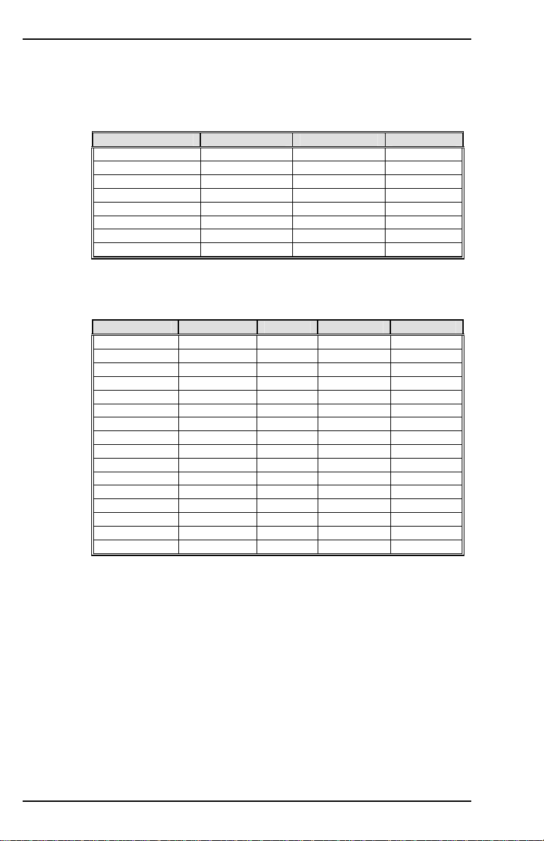
DIR
Sets the direction (inversion) of many different parameters with respect
to the rotation of the motor; as viewed looking at the end of the shaft.
Variable Syntax: DIR <first parameter> <second parameter> <third
parameter>
This variable switch was greatly expanded for SERCOS
use with the introduction of firmware version 3.4.0.
Historically, it was a two-position switch with the following
definition:
NOTE
For Non-SERCOS Users:
Only the first parameter should be used to affect performance; and even
then, only the parameters 0 or 1. Therefore, the standard user need only
configure the first parameter (0 for CCW and 1 for CW) to control all
three loops simultaneously. If you query the variable, all three
parameters are communicated even though only one was changed. Just
leave the second and third at the default settings.
0 = positive motion is counter-clockwise (CCW)
1 = positive motion is clockwise (CW)
Parameter Position Velocity Torque
0
1
VarCom Reference M-SS-017-04 Rev. M 17
1 1 1
0 0 0
Page 26
VARIABLE AND COMMAND LIST 09/05 Danaher Motion
For SERCOS Users:
The SERCOS interface only affects the position command and position
feedback polarities.
First Parameter: sets the direction (inversion) of the Position command,
Velocity command, and Torque command.
Parameter Position Velocity Torque
0
1
2
3
4
5
6
7
1 1 1
0 0 0
0 1 0
0 1 1
1 0 0
1 0 1
1 1 0
0 0 1
Second Parameter: sets the direction (inversion) of the External
Position feedback, Motor Position feedback, Velocity feedback, Torque
feedback.
Parameter External Motor Velocity Torque
0
1
2
3
4
5
6
7
8
9
10
11
12
13
14
15
0 0 0 0
0 0 0 1
0 0 1 0
0 0 1 1
0 1 0 0
0 1 0 1
0 1 1 0
0 1 1 1
1 0 0 0
1 0 0 1
1 0 1 0
1 0 1 1
1 1 0 0
1 1 0 1
1 1 1 0
1 1 1 1
Third Parameter: sets the direction (inversion) of the Position Additive
command, Velocity Additive command, Torque Additive command. This
parameter is currently not supported.
Firmware Versions: All Type: switch (R/W)
Range: Refer to tables Default: 1, 0, 0
Opmodes: All Drive Status: EN/DIS
Units: N/A EEPROM: Yes
DIS
Disables the drive. Software servo loops are halted and power is
disconnected from the motor. The function is immediate and the motor
may coast.
Firmware Versions: All Command Syntax: DIS
Opmodes: All Drive Status: EN/DIS
18 M-SS-017-04 Rev. M VarCom Reference
Page 27

Danaher Motion 09/05 VARIABLE AND COMMAND LIST
DISSPEED
Sets the speed window for the Active Disable function. The Active
Disable function ramps the motor to zero speed using DECSTOP.
DISSPEED is compared to the actual motor speed, and if the speed is
less than this value, the active disable timer (DISTIME) will begin timing.
Once the timer times out, the drive disables..
Firmware Versions: 2.1.0 and later Type: variable (R/W)
Units: rotary: rpm
linear: mm/sec/sec
Opmodes: All Drive Status: EN/DIS
EEPROM: Yes
Range: 0 to 14,999
Default: 50 rpm
DISTIME
Sets the amount of time to wait after motor speed goes below
DISSPEED before the drive is disabled in the Active Disable process.
Once motor speed goes below DISSPEED, the drive waits for the time
period specified by DISTIME, and then disables the drive..
Firmware Versions: 2.1.0 and later Type: variable (R/W)
Range: 0 to 65535 Default: 100
Opmodes: All Drive Status: EN/DIS
Units: millisecond * 0.1 EEPROM: Yes
DIVISIONS
Sets the number of divisions used for indexing (divides PROTARY).
Only used when MODMODE = 1
NOTE
Firmware Versions: 3.7.0 and later
Default: 4
EEPROM: Yes
Range: 2 to 32767
-2 to -32767
DRIVEOK
Displays the status of the drive faults.
0 = faults exist
1 = no faults exist
Firmware Versions: All Type: switch (R/W)
Range: 0, 1 Default: N/A
Opmodes: All Drive Status: EN/DIS
Units: N/A EEPROM: No
VarCom Reference M-SS-017-04 Rev. M 19
Page 28

VARIABLE AND COMMAND LIST 09/05 Danaher Motion
DUMP
Transmits all variables and their settings to the serial port terminal. This
command actually outputs the EEPROM contents of the drive to the
serial port, where the variables can then be reviewed or saved to a
variable file (*.SSV).
Firmware Versions: All Command Syntax: DUMP
Opmodes: All Drive Status: EN/DIS
DUALFB
Enables/disables the reading of an external feedback signal through the
C8 connector.
0 = no dual loop
1 = dual loop without checking for external feedback fault
2 = dual loop with checking for external feedback fault
The fault options above can relate to a line break. However,
the motor must be in motion for this detection to occur. It
NOTE
Firmware Versions: 3.3 and later Type: switch (R/W)
Range: 0, 1, 2 Default: 0
Opmodes: 8 Drive Status: DIS
Units: N/A EEPROM: Yes
also indicates a wrong XENDIR parameter.
ECHO
Enables/disables serial port character echo. If echo is enabled,
characters received via the serial port are echoed back to the serial port
and displayed on the MOTIONLINK monitor or terminal.
0 = serial port echo disabled
1 = serial port echo enabled
ECHO = 1 is needed for proper operation of MOTIONLINK.
NOTE
Firmware Versions: All Type: switch (R/W)
Range: 0, 1 Default: 1
Opmodes: All Drive Status: EN/DIS
Units: N/A EEPROM: Yes
EN
Initiates a software enable of the drive. EN first attempts to reset any
existing fault conditions, then sets SWEN to 1. If READY, REMOTE,
and DIPEN are equal to one, the drive becomes ACTIVE. Checking the
value of ACTIVE allows you to see if EN successfully enabled the drive.
Firmware Versions: All Command Syntax: EN
Opmodes: All Drive Status: EN/DIS
20 M-SS-017-04 Rev. M VarCom Reference
Page 29

Danaher Motion 09/05 VARIABLE AND COMMAND LIST
ENCINIT
Triggers the encoder initialization process for type 0-2 and type 7
encoders. The initialization process requires rotating the motor until the
encoder index is found. Then, the drive sets the value of MENCOFF.
If the drive is enabled and in Opmode=0, JOG is used to rotate the
motor. When the encoder index is encountered, the drive sets the value
of MENCOFF. In this case, the status of ENCINIT is observed using
ENCINITST.
Firmware Versions: All Command Syntax: ENCINIT
Opmodes: All Drive Status: DIS
ENCINITST
Displays the status of the encoder initialization function. This variable is
reset to 0 when manually set to the index position.
0 = initialization process has not begun
1 = encoder initialization is in progress
2 = encoder initialization has been completed
Firmware Versions: All Type: switch mode (R)
Range: 0, 1, 2 Default: N/A
Opmodes: All Drive Status: EN/DIS
Units: N/A EEPROM: No
ENCOUT
Sets the resolution (number of lines) of the encoder equivalent output
channel only for resolver based systems. For encoder-based
systems, this variable is read-only and is set equal to MENCRES (for
firmware versions prior to 3.3.0) or MENCRES / ENCOUTO (for
firmware versions 3.3.0 and later). For sine encoder-based systems, this
variable is read-only and is set equal to MENCRES * SININTOUT /
ENCOUTO.
ENCOUT values of 2048 and 4096 are available only
when VLIM < 6100 rpm (RDRES = 14 or RDRES = 16).
ENCOUT values of 8192 and 16384 are available only
when VLIM <=1500 rpm (RDRES = 16). In the majority
NOTE
Firmware Versions: All Type: switch mode (R/W)
Units: lines per electrical
revolution of the resolver
Opmodes: All Default: 1024
EEPROM: Yes Drive Status: DIS
VarCom Reference M-SS-017-04 Rev. M 21
of resolvers, one electrical revolution = one
mechanical revolution.
Range: 512, 1024, 2048, 4096, 8192,
or 16384
Page 30

VARIABLE AND COMMAND LIST 09/05 Danaher Motion
ENCOUTMOD
Queries or sets the encoder simulation signal format. When set to 0, the
encoder simulation signal has the A-quad-B format, with A leading B for
positive rotation. When set to the value 1, the encoder simulation signal
has a pulse up/down format. When motion is positive, an encoder pulse
train is generated on the A signal and no signal is generated on the B
signal line. When motion is negative, an encoder pulse train is
generated on the B signal and the A signal line is forced low.
Syntax for set: ENCOUTMOD <value> Default: 0
Syntax for query: ENCOUTMOD Opmodes: All
Type: Switch variable (R/W) Drive Status: Disabled
Range: 0: Encoder simulation has A-quad-B format
1: Encoder simulation has pulse up/down format
Firmware: Version 6.2.0 and later EEPROM: Yes
Limitations: Not yet supported by MOTIONLINK
ENCOUTO
Sets the value of a scale-down factor only for the encoder equivalent
output channel (ENCOUT) for encoder and sine encoder-based
systems. For encoder-based systems with firmware versions 3.3.0 or
later, ENCOUT = MENCRES / ENCOUTO. For sine encoder-based
systems, ENCOUT = MENCRES * SININTOUT / ENCOUTO.
Firmware Versions: All Type: switch mode (R)
Range: 1, 2, 4, 8, 16 Default: 1
Opmodes: All Drive Status: DIS
Units: N/A EEPROM: Yes
ENCSTART
Triggers the encoder initialization process for encoder types 1-4 and 6.
In the initialization process, the drive rotates the motor to a known
electrical position by placing IENCSTART current from the motor B
terminal to the motor C terminal. If the encoder index is encountered (for
type 1 and 2 encoders), the process terminates immediately. The
ENCSTART process is initiated by doing the following:
1. With the drive disabled, type ENCSTART.
2. Enable the drive. The current is placed on the motor terminals
and the initialization process is completed after the drive
enable occurs.
Enable is inhibited until this command is executed (for encoder types 1
and 3). The status display flashes the current OPMODE at 3 Hz as a
visual indicator that the encoder is not initialized yet.
Firmware Versions: All Command Syntax: ENCSTART
Opmodes: All Drive Status: DIS
22 M-SS-017-04 Rev. M VarCom Reference
Page 31

Danaher Motion 09/05 VARIABLE AND COMMAND LIST
ERR
Displays the last error detected by the drive. A numeric code and a short
explanatory string are output to the serial port if MSG = 1. The error
buffer is cleared when the drive undergoes a transition from disabled
(DIS) to enabled (EN).
Firmware Versions: All Command Syntax: ERR
Opmodes: All Drive Status: EN/DIS
FILTMODE
Sets the velocity loop filter mode.
No LPF.
0
1 A single first order filter. Cutoff frequency is LPFHZ1.
2 Two first order filters. Cutoff frequencies are LPFHZ1 and
LPFHZ2.
3 Notch filter. Frequency NOTCHHZ, bandwidth NOTCHBW.
Available only if firmware version (VER) is 3.1.0 or greater.
The filters affect the PI, PDFF, and standard pole placement controllers
(COMPMODES 0-2 and 4), and are ignored in the advanced pole
placement controller (COMPMODE=3).
Firmware Versions: All Type: switch mode (R/W)
Range: 0, 1, 2 Default: 0
Opmodes: 0,1,4,8 Drive Status: EN/DIS
Units: N/A EEPROM: Yes
FLTCLR
Clears the fault history buffer, (contains up to 10 faults).
Firmware Versions: All Command Syntax: FLTCLR
Opmodes: All Drive Status: EN/DIS
FLTHIST
Causes the drive to transmit the fault history buffer to the serial port.
The most recent fault is sent first. Up to 10 fault messages are output by
the drive, with each fault message followed by a CR-LF. A time stamp in
the format of hours:minutes is displayed along with each fault, indicating
the time at which the fault occurred.
Firmware Versions: All Command Syntax: FLTHIST
Opmodes: All Drive Status: EN/DIS
VarCom Reference M-SS-017-04 Rev. M 23
Page 32

VARIABLE AND COMMAND LIST 09/05 Danaher Motion
FOLD
Displays the status of the drive foldback circuit. When the system
current level exceeds ICONT for too long, the drive enters foldback
mode, FOLD changes from 0 to 1, and the drive current is limited
gradually (in exponential fashion) to the value of ICONT.
0 = drive foldback OFF
1 = drive foldback ON
Firmware Versions: All Type: switch (R)
Range: 0, 1 Default: 0
Opmodes: All Drive Status: EN/DIS
Units: N/A EEPROM: No
FOLDMODE
Sets the mode for drive current foldback and motor current foldback
operation.
0 = normal foldback from ILIM to ICONT
1 = foldback to ICONT and issue fault after FOLDTIME
2 = issue fault immediately upon detection
Firmware Versions: All Type: switch mode (R/W)
Range: 0, 1, 2 Default: 0
Opmodes: All Drive Status: EN/DIS
Units: N/A EEPROM: Yes
FOLDTIME
Sets the time since foldback detection to foldback fault latch (for
FOLDMODE=1 only).
0 = normal foldback from ILIM to ICONT.
Firmware Versions: 2.1.0 and later Type: variable (R/W)
Range: 1 to 300 Default: 30
Opmodes: All Drive Status: EN/DIS
Units: seconds EEPROM: Yes
GEAR
Enables and disables electronic gearing. GEAR is an immediate
command (causes immediate gearing) unless INxMODE is selected to
allow hardware control. If INxMODE is selected to control this function,
this serial command must be 1 and the INx input must be on to enable
the gear function. GEAR is a velocity-lock function so any bits lost
during unlock time or ramp-to-speed are lost.
Firmware Versions: 2.1.0 and later Type: switch (R/W)
Range: 0 (OFF), 1 (ON) Default: 1
Opmodes: 4 Drive Status: EN/DIS
Units: N/A EEPROM: Yes
24 M-SS-017-04 Rev. M VarCom Reference
Page 33

Danaher Motion 09/05 VARIABLE AND COMMAND LIST
GEARI
Specifies the number of teeth on the input gear for the Gearing mode.
Firmware Versions: 2.1.0 and later Type: variable (R/W)
Range: -32767 to + 32767 Default: 1
Opmodes: 4 Drive Status: EN/DIS
Units: N/A EEPROM: Yes
GEARMODE
This is a switch mode variable that specifies the operation of electronic
gearing for OPMODE 4:
GEARMODE = 0 - Encoder Follower, Flex I/O (Connector C3)
Inputs: The encoder input channel is decoded as a quadrature input,
scaled through GEARI / GEARO, and becomes the position command
for the motor. The digital I/O (Flex I/O) inputs serve as the encoder input
channel (see note below for clarification).
GEARMODE = 1 - Pulse and Direction, Flex I/O (Connector C3)
Inputs: The encoder input channel A counts positive edges and
becomes the position command. The encoder input channel B level
dictates if the counter will count up or down. Channel B low drives motor
in CW direction. The digital I/O (Flex I/O) inputs serve as the encoder
input channel (see note below for clarification).
GEARMODE = 2 - Up/Down Mode, Flex I/O (Connector C3) Inputs:
The encoder input channel is configured as a counter to command the
motor’s position. Positive edges on the A channel increments the
counter (motor CW) while positive edges on the encoder input channel
B decrements the counter (motor CCW). The digital I/O (Flex I/O) inputs
serve as the encoder input channel (see note below for clarification).
GEARMODE = 3 - Encoder Follower, Remote Encoder (Connector
C8) Inputs: The encoder input channel is decoded as a quadrature
input, scaled through GEARI / GEARO, and becomes the position
command for the motor. The remote encoder (handwheel) inputs serve
as the encoder input channel (see note below for clarification).
GEARMODE = 4 - Pulse and Direction, Remote Encoder (Connector
C8) Inputs: The encoder input channel A counts positive edges and
becomes the position command. The encoder input channel B level
dictates if the counter will count up or down. Channel B low drives motor
in CW direction. The remote encoder (handwheel) inputs serve as the
encoder input channel (see note below for clarification).
GEARMODE = 5 - Up/Down Mode, Remote Encoder (Connector C8)
Inputs: The encoder input channel is configured as a counter to
command the motor’s position. Positive edges on the A channel
increments the counter (motor CW) while positive edges on the encoder
input channel B decrements the counter (motor CCW). The remote
encoder (handwheel) inputs serve as the encoder input channel (see
note below for clarification).
VarCom Reference M-SS-017-04 Rev. M 25
Page 34

VARIABLE AND COMMAND LIST 09/05 Danaher Motion
NOTE
Firmware Versions: 2.1.0 and later Type: switch mode (R/W)
Range: 0 to 5 Default: 3
Opmodes: 4 Drive Status: DIS
Units: N/A EEPROM: Yes
If GEARMODE = 0-2, encoder A/B inputs are received via
the digital Flex I/O inputs on connector C3. If GEARMODE =
3-5, encoder A/B inputs are received via the remote encoder
(handwheel) inputs on connector C8.
Each of these modes are subject to: GEARI, GEARO, GEAR,
and DIR.
GEARO
Specifies the number of teeth on the output gear for the Gearing mode.
Firmware Versions: 2.1.0 and later Type: variable (R/W)
Range: 1 to 32767 Default: 1
Opmodes: 4 Drive Status: EN/DIS
Units: teeth EEPROM: Yes
GET
Causes all recorded variables to be transmitted to the serial port for use
with PC Scope. The data format is defined by GETMODE.
Firmware Versions: All Command Syntax: GET
Opmodes: All Drive Status: EN/DIS
GETMODE
Sets the mode of data transfer from the drive to the host when using
GET.
0 = ASCII data transfer format
1 = ASCII-HEX data transfer format
2 = BINARY data transfer format (fastest)
GETMODE=0 is needed for operation of MOTIONLINK.
26 M-SS-017-04 Rev. M VarCom Reference
NOTE
Firmware Versions: All Type: switch mode (R/W)
Range: 0, 1, 2 Default: 0
Opmodes: All Drive Status: EN/DIS
Units: N/A EEPROM: Yes
Page 35

Danaher Motion 09/05 VARIABLE AND COMMAND LIST
GP
Sets the proportional gain for the position loop. Executing TUNE
successfully may change the value of this parameter.
Firmware Versions: 2.1.0 and later Type: variable (R/W)
Units: rotary: 0.01 krpm/rev
linear: 0.01 m/min/mm
Drive Status: EN/DIS
EEPROM: Yes
Range: 1 to 7000
Default: calculated
Opmodes: 4,8
GPAFR
This is a position loop feedforward acceleration gain term. This term is
applied in the position loop and is used to create an acceleration
feedforward input to the current loop.
Firmware Versions: 3.1.0 and later Type: variable (R/W)
Range: 0 to 2000 Default: 0
Opmodes: 4,8 Drive Status: EN/DIS
Units: 0.1% EEPROM: Yes
GPAFR2
This is a second position loop feedforward acceleration gain term. This
term is applied in the position loop and is used to create an acceleration
feedforward input to the velocity loop.
Prior to firmware version 3.2.0, the range was 0 to 2000.
NOTE
Firmware Versions: 3.1.0 and later Type: variable (R/W)
Range: -10,000 to +10,000 Default: 0
Opmodes: 4,8 Drive Status: EN/DIS
Units: 0.1% EEPROM: Yes
GPD
Sets the derivative gain for the Proportional-Integral-Derivative (PID)
compensator in the position loop.
Firmware Versions: 3.1.0 and later Type: variable (R/W)
Range: 0 to 32767 Default: 0
Opmodes: 4, 8 Drive Status: EN/DIS
Units: N/A (1000=unity gain) EEPROM: Yes
VarCom Reference M-SS-017-04 Rev. M 27
Page 36

VARIABLE AND COMMAND LIST 09/05 Danaher Motion
GPI
Sets the integral gain for the Proportional-Integral-Derivative (PID)
compensator in the position loop. Setting this value = 10,000 means that
GPI=GP (expressed mathematically, the internal PID gain used by the
drive processor equals GP*GPI/10000).
Firmware Versions: 3.1.0 and later Type: variable (R/W)
Range: 0 to 10000 Default: 0
Opmodes: 4, 8 Drive Status: EN/DIS
Units: N/A EEPROM: Yes
GPISATIN
Limits the input of the position loop integrator by setting the input
saturation. When used in concert with GPISATOUT, this variable
enables the operator to make the position loop integrator effective near
the target position, whereas far from the target position, the integrator is
not dominant in the loop dynamics.
Firmware Versions: 3.1.0 and later Type: variable (R/W)
Range: 0 to 1,000,000 Default: 0
Opmodes: 4, 8 Drive Status: EN/DIS
Units: feedback counts EEPROM: Yes
GPISATOUT
Limits the output of the position loop integrator by setting the output
saturation. When used in concert with GPISATIN, this variable enables
the operator to make the position loop integrator effective near the
target position, whereas far from the target position, the integrator is not
dominant in the loop dynamics.
Firmware Versions: 3.1.0 and later Type: variable (R/W)
Range: 0 to 1,000,000 Default: 0
Opmodes: 4, 8 Drive Status: EN/DIS
Units: feedback counts EEPROM: Yes
GPVFR
This is a position loop feedforward velocity gain term. This term is
applied in the position loop and is used to create a feedforward input to
the velocity loop.
Firmware Versions: 3.1.0 and later Type: variable (R/W)
Range: 0 to 2000 Default: 0
Opmodes: 4, 8 Drive Status: EN/DIS
Units: 0.1% EEPROM: Yes
28 M-SS-017-04 Rev. M VarCom Reference
Page 37

Danaher Motion 09/05 VARIABLE AND COMMAND LIST
GV
Sets the proportional gain for the Proportional Integral Velocity Control
Loop (PI loop; COMPMODE = 0). Executing TUNE successfully may
change the value of this parameter.
Firmware Versions: All
Range: 0 to 1,000,000,000 (firmware versions 3.3.0 and later)
Default: 500 Type: variable (R/W)
Units: N/A EEPROM: Yes
Opmodes: 0,1,4,8 Drive Status: EN/DIS
0 to 65,535 (firmware versions 2.2.0 to 3.2.1)
0 to 32,767 (firmware versions up to 2.2.0)
GVI
Sets the velocity integral gain for the Proportional Integral Velocity
Control Loop (PI loop; COMPMODE = 0). Executing TUNE
successfully may change the value of this parameter.
Firmware Versions: All Type: variable (R/W) Range: 0 to 65535 Default: 20 Opmodes: 0,1,4,8 Drive Status: EN/DIS Units: N/A EEPROM: Yes
HALLS
Returns the hall switch values (encoder feedback option only). The
switch values are displayed as a three-bit code in the sequence C-B-A.
Firmware Versions: All Type: switch mode (R)
Range: 000 to 111 Default: N/A
Opmodes: 2 and 3 Drive Status: EN/DIS
Units: bits EEPROM: No
HCMODE
Selects the harmonic correction mode of operation.
0 – Disabled
1 – Harmony HC1 corrects position feedback used for velocity
(resolver systems), harmonics HC2, HC3 summed and correct
the torque command.
2 – All harmonies are summed and used for torque correction.
3 – All harmonies are summed and used for resolver feedback
correction (for velocity only.)
4 – Harmony HC1 and HC2 are summed to correct position
feedback used for velocity (resolver systems,) harmony HC3
corrects the torque command.
This command does not operate in torque Opmodes (2 and 3).
Firmware Versions: 3.4 and later Type: switch (R/W)
Range: 0 to 4 Default: 0
Opmodes: 0, 1, 4, 5, 6, 7, 8 Drive Status: EN/DIS
Units: N/A EEPROM: No
VarCom Reference M-SS-017-04 Rev. M 29
Page 38

VARIABLE AND COMMAND LIST 09/05 Danaher Motion
HC1
Defines the properties of correction harmony number 1.
Syntax: HC1<harmonic number> <phase offset> <amplitude>
Units:
<harmonic number>: N/A
<phase offset>: degrees
(PRD cycle = 360º)
<amplitude>: counts
Type: variable (R/W)
EEPROM: Yes
Opmodes: All
Drive Status: EN/DIS
Default:
<harmonic number>: 2
<phase offset>: 0
<amplitude>: 0
<harmonic number> sets the number of cycles per resolver cycle
(resolver system) or per motor
revolution (encoder system.)
<phase offset> relative to resolver zero (resolver system) or PRD
zero (encoder system.)
<amplitude> specifies the amplitude of the harmony in internal
counts at the injection point.
Range: Versions 3.7.0 and below:
<harmonic number>: 1 to 1000
<phase offset>: 0 to 359
<amplitude>: 0 to 16384
Versions 4.0.1 and later:
<harmonic number>: 1 to 8192
<phase offset>: 0 to 359
<amplitude>: 0 to 16384
HC2
Defines the properties of correction harmony number 2.
Syntax: HC2<harmonic number> <phase offset> <amplitude>
Units:
<harmonic number>: N/A
<phase offset>: degrees
(PRD cycle = 360º)
<amplitude>: counts
Type: variable (R/W)
EEPROM: Yes
Opmodes: All
Drive Status: EN/DIS
Default:
<harmonic number>: 2
<phase offset>: 0
<amplitude>: 0
<harmonic number> sets the number of cycles per resolver cycle
(resolver system) or per motor revolution
(encoder system.)
<phase offset> relative to resolver zero (resolver system) or PRD
zero (encoder system.)
<amplitude> specifies the amplitude of the harmony in internal
counts at the injection point.
Range: Versions 3.7.0 and below:
<harmonic number>: 1 to 1000
<phase offset>: 0 to 359
<amplitude>: 0 to 16384
Versions 4.0.1 and later:
<harmonic number>: 1 to 8192
<phase offset>: 0 to 359
<amplitude>: 0 to 16384
30 M-SS-017-04 Rev. M VarCom Reference
Page 39

Danaher Motion 09/05 VARIABLE AND COMMAND LIST
HC3
Defines the properties of correction harmony number 3.
Units:
<harmonic number>: N/A
<phase offset>: degrees
(PRD cycle = 360º)
<amplitude>: counts
Type: variable (R/W)
EEPROM: Yes
Opmodes: All
Drive Status: EN/DIS
Range: Versions 3.7.0 and below:
<harmonic number>: 1 to 1000
<phase offset>: 0 to 359
<amplitude>: 0 to 16384
Versions 4.0.1 and later:
<harmonic number>: 1 to 8192
<phase offset>: 0 to 359
<amplitude>: 0 to 16384
Default:
<harmonic number>: 2
<phase offset>: 0
<amplitude>: 0
HOLD
Sets a flag indicating whether or not the drive should enter the positionhold mode. When activated, the motor will decelerate to zero speed at
the DECSTOP rate and switch modes to hold the motor shaft at its
present position. This variable may be set either by serial
communication, by asserting both limit switches (CWLIM and CCWLIM),
or by setting DIP switch number 7, or during active disable. The Status
Display will flash the current OPMODE as a visual indicator that the
drive is in the HOLD mode.
Firmware Versions: All Type: switch (R/W)
Range: 0, 1 Default: 0
Opmodes: All Drive Status: EN/DIS
Units: N/A EEPROM: No
HOMESPD
Sets the homing speed and direction (first time initialize) for INxMODE
10-12 and MH. A positive speed is CW.
Firmware Versions: 3.1.0 and later Type: variable (R/W)
Units: rotary: rpm
linear: mm/sec
Opmodes: 8 Drive Status: EN/DIS
EEPROM: Yes
Range: -VMAX to VMAX
Default: 100
HOMESTATE
Returns the status of the homing function. This variable can be polled
during homing to track the homing status. A homing process may not go
through all of the steps listed below, which are a chronological listing of
the steps taken during a full homing procedure that begins when homing
is initiated with a home switch that is already pressed. When this
process is complete, home or absolute machine zero is known and
PFB=0.
0 = no drive controlled homing has been initiated.
1 = homing started; moving away from pressed home switch.
2 = waiting for home switch to clear; drive will stop when it does.
VarCom Reference M-SS-017-04 Rev. M 31
Page 40

VARIABLE AND COMMAND LIST 09/05 Danaher Motion
3 = home switch has cleared; check if drive is stopped.
4 = home search; move towards home switch.
5 = waiting for home switch to be pressed; drive will stop.
6 = home switch detected; check if motor is stopped.
7 = after motion stops, motor will go home.
8 = check if motor is at home.
9 = motor is at home, waiting for in-position.
10 = homing is complete.
11 = homing process was interrupted during execution.
12 = homing was canceled, waiting for the motor to stop (SERCOS
only).
Firmware Versions: 3.1.0 to 3.3.0, 3.4.2 and later.
For Firmware Versions 3.4.0 and 3.4.1, contact Customer Support for a
comprehensive definition of HOMESTATE.
EEPROM: N/A Units: N/A
Drive Status: EN/DIS Opmodes: 8
Type: switch mode (R) Default: N/A
Range: 0 to 12
HOMETYPE
Defines the type of homing function performed. This variable takes on a
different meaning depending on the type of positioning selected (using
PCMDMODE). In the following descriptions, Home switch refers to a
digital input (IN1-IN3) that has been configured as a home switch by
setting INxMODE = 10. Marker refers to an encoder’s index pulse or a
resolver zero point:
In Serial Position Mode (PCMDMODE = 0. PFB is normalized to zero
after the home search):
0 homing with home switch and marker (PFB = 0).
1 homing with home switch only (PFB = 0).
2 homing with marker only (PFB = 0).
3 present position is home on the rising edge of IN1, IN2, or IN3
with the corresponding INxMODE value set to 12 (PFB=0).
4 homing on marker with every drive enable, MH, or on the rising
edge of IN1-IN3 with the corresponding INxMODE set equal to
12 (PFB=0).
5 homing on marker with every MH command, or on the rising
edge of IN1-IN3 with the corresponding INxMODE set equal to
12 (PFB=0).
6 homing with home switch and marker (PFB=0) on every MH
(firmware versions 3.3.0 and later).
7 homing with home switch only (PFB=0) on every MH (firmware
versions 3.3.0 and later).
For HOMETYPE 0 to 3, the first execution of the homing
command initiates a search for absolute machine zero.
Executing successive homing commands causes an
absolute move to zero position without searching for
NOTE
machine zero. For HOMETYPE 4 to 7, the drive searches for
absolute machine zero on every home command, whether
absolute machine zero has previously been detected or not.
32 M-SS-017-04 Rev. M VarCom Reference
Page 41

Danaher Motion 09/05 VARIABLE AND COMMAND LIST
In Analog Position Mode (PCMDMODE = 1):
HOMETYPES 0 to 7 are the same as for Serial Position Mode. When
homing is complete, PFB is normalized (set equal to 0) at the current
value of the analog input (ANIN). Example: when homing is complete, if
2 volts are present at the analog input, PFB is set equal to 0 at 2 volts of
input.
HOMETYPES 50 to 57 are the same as 0-7, except that when homing
is complete, PFB is not normalized at the current value of ANIN.
Instead, PFB is normalized at 0 volts input.
If there is a voltage on the analog input other than 0 V and
the drive is enabled, the motor will see this as a command
to move and move to the position specified by the analog
input voltage.
CAUTION
Firmware revision information: prior to firmware version 3.3.0, only
Analog Position Mode HOMETYPES 0 and 3 were available.
Firmware Versions: 3.1.0 and later Type: switch mode (R/W)
Range: 0 to 7 (analog and serial position modes)
50-57 (analog position mode only)
Units: N/A EEPROM: Yes
Opmodes: 8 Drive Status: EN/DIS
Default: 0
HSAVE
Copies MPHASE, PFBOFF and ZPOS into the EnDat encoder memory.
Care must be taken when overwriting MPHASE as runaway conditions
are possible with incorrect values. HSAVE is applicable only when
MENCTYPE=9.
Firmware Versions: 3.6.0 and later Command Syntax: HSAVE
Opmodes: All Drive Status: EN/DIS
HWPOS
Displays the position feedback directly from the feedback hardware
counter. For resolver-based systems, HWPOS ranges from 0 to 65,535
per electrical revolution of the resolver (the number of electrical resolver
revolutions per each mechanical revolution is calculated by dividing the
number of resolver poles by 2). The resolution of HWPOS is based on
RDRES:
RDRES = 12, resolution of HWPOS = 16
RDRES = 14, resolution of HWPOS = 4
RDRES = 16, resolution of HWPOS = 1
For encoder-based systems, HWPOS returns the encoder counter
content, based on quadrature pulse input and ranges from 0 to 65535,
with a resolution of 32.
Firmware Versions: 2.0.0 and later Type: variable (R)
Range: 0 to 65,535 Default: N/A
Opmodes: All Drive Status: EN/DIS
Units: counts EEPROM: No
VarCom Reference M-SS-017-04 Rev. M 33
Page 42

VARIABLE AND COMMAND LIST 09/05 Danaher Motion
I
Displays the motor current. The AVGTIME variable determines the
averaging of this variable, except when recorded for graphical display by
MOTIONLINK, in which case it is not averaged.
Firmware Versions: All Type: variable (R)
Range: 0 to 2000 Default: N/A
Opmodes: All Drive Status: EN/DIS
Units: % of DIPEAK * 0.1 EEPROM: No
IA
Displays the motor’s A phase current. AVGTIME does not affect this
variable.
Firmware Versions: All Type: variable (R)
Range: -1000 to 1000 Default: N/A
Opmodes: All Drive Status: EN/DIS
Units: % of DIPEAK * 0.1 EEPROM: No
IAOFF
Displays the motor’s A phase current. Offset value or used (with
AUTONULL=2) to establish (W*)the A-phase current offset.
Firmware Versions: All Type: variable (R/W*)
Range: -1000 to 1000 Default: See AUTONULL
Opmodes: All Drive Status: EN/DIS
Units: internal bits EEPROM: Yes
IC
Displays the motor’s C phase current. AVGTIME does not affect this
variable.
Firmware Versions: All Type: variable (R)
Range: -1000 to 1000 Default: N/A
Opmodes: All Drive Status: EN/DIS
Units: % of DIPEAK * 0.1 EEPROM: No
ICOFF
Displays the motor’s A phase current. Offset value or used (with
AUTONULL=2) to establish (W*)the C-Phase current offset.
Firmware Versions: All Type: variable (R/W*)
Range: -1000 to 1000 Default: See AUTONULL
Opmodes: All Drive Status: EN/DIS
Units: internal bits EEPROM: Yes
34 M-SS-017-04 Rev. M VarCom Reference
Page 43

Danaher Motion 09/05 VARIABLE AND COMMAND LIST
ICMD
Displays the Current (Torque) command to the current controller. This
variable is equivalent to the Analog Input (ANIN) in OPMODE 3, to the
Torque Command (T) in OPMODE 2, and to the output of the velocity
controller in OPMODE 0 or 1. The AVGTIME variable affects averaging
of this variable, except when recorded for graphical display by
MOTIONLINK, in which case it is not averaged.
Firmware Versions: All Type: variable (R)
Range: -1000 to 1000 Default: N/A
Opmodes: All Drive Status: EN/DIS
Units: % of DIPEAK * 0.1 EEPROM: No
ICONT
Sets the system continuous current. This variable is used in the foldback
algorithm. The default value of this variable is the minimum of DICONT
(Drive Continuous Current) and MICONT (Motor Continuous Current),
unless that value exceeds IMAX, in which case ICONT is set equal to
IMAX. This variable is reset to its default whenever DICONT or MICONT
is changed. You can override the default.
Firmware Versions: All Type: variable (R/W)
Range: 0 to IMAX Default: min of DICONT & MICONT
Opmodes: All Drive Status: EN/DIS
Units: % of DIPEAK * 0.1 EEPROM: Yes
IENCSTART
Sets the maximum current for the ENCSTART encoder initialization
process.
Firmware Versions: All Type: variable (R/W)
Range: 1 to 100 Default: 25
Opmodes: All Drive Status: EN/DIS
Units: % of MICONT EEPROM: Yes
IFRIC
This is the Coulomb Friction constant for the current loop.
Firmware Versions: 2.1.0 and later Type: variable (R/W)
Range: 0 to 500 Default: 0
Opmodes: 8 Drive Status: EN/DIS
Units: % of DIPEAK EEPROM: Yes
IGRAV
This is the Gravity constant for the current loop.
Firmware Versions: 2.1.0 and later Type: variable (R/W)
Range: -500 to 500 Default: 0
Opmodes: 8 Drive Status: EN/DIS
Units: % of DIPEAK EEPROM: Yes
VarCom Reference M-SS-017-04 Rev. M 35
Page 44

VARIABLE AND COMMAND LIST 09/05 Danaher Motion
ILIM
Sets the application current limit, allowing the user to limit the drive’s
peak current. This variable limits the current command that will be
accepted from the user (using the T command in Opmode 2) or issued
by the control loops (in Opmodes 0, 1, 3, and 4). This variable is an
independent variable that is not calculated from hardware parameters
and is not tied to any other variables. ILIM is similar to VLIM (which is
used in Opmodes 0 and 1) and is used to protect delicate load
equipment.
Firmware Versions: All Type: variable (R/W)
Range: 0 to IMAX Default: IMAX
Opmodes: All Drive Status: EN/DIS
Units: % of DIPEAK * 0.1 EEPROM: Yes
ILIM2
This variable is used to define a new current limit value for INxMODE 8.
This variable functions in similar fashion to ILIM if INxMODE = 8 and the
corresponding INx input = 1.
Firmware Versions: 3.1.0 and later Type: variable (R/W)
Range: 0 to IMAX Default: 0.1 * IMAX
Opmodes: All Drive Status: EN/DIS
Units: % of DIPEAK * 0.1 EEPROM: Yes
ILSBMODE
(Relevant for resolver feedback only.) Sets the mode of operation of the
inter-LSB algorithm, which interpolates feedback between least
significant bits (LSB’s) of the resolver. Enabling this algorithm will
improve performance when the RDRES resolution is low (12 bits), BW is
high, and the commanded velocity is low.
ILSBMODE = 0; algorithm disabled
ILSBMODE = 1; enabled for velocity feedback.
ILSBMODE = 2; enabled for velocity and position feedback
Firmware Versions: 2.1.0 and later Type: switch mode (R/W)
Range: 0, 1, 2 Default: 2
Opmodes: 0,1,4,8 Drive Status: DIS
Units: N/A EEPROM: Yes
IMAX
Displays the system current maximum for a drive and motor
combination. This variable is actually the minimum of the drive Peak
Current (DIPEAK) and the Motor Peak Current (MIPEAK).
Firmware Versions: All Type: variable (R)
Range: 0 to 1000 Default: min of DIPEAK & MIPEAK
Opmodes: All Drive Status: EN/DIS
Units: % of DIPEAK *0.1 EEPROM: No
36 M-SS-017-04 Rev. M VarCom Reference
Page 45

Danaher Motion 09/05 VARIABLE AND COMMAND LIST
IN
Returns the state of the three digital inputs (IN1, IN2, IN3) in a threecharacter string. The leftmost bit represents IN1 and the rightmost bit
represents IN3.
Firmware Versions: 3.1.0 and later Type: switch mode (R)
Range: 000 to 111 (0=OFF, 1=ON) Default: N/A
Opmodes: All Drive Status: EN/DIS
Units: N/A EEPROM: N/A
IN1
This is used to read the state of the hardware input on user connector
C3 Pin 9.
Firmware Versions: 2.1.0 and later Type: switch (R)
Range: 0 (OFF), 1=(ON) Default: N/A
Opmodes: All Drive Status: EN/DIS
Units: N/A EEPROM: N/A
IN1MODE
IN1MODE sets the functionality of the IN1 input. The functions are:
IN1MODE=0: No function*
IN1MODE=1: CW limit switch*
IN1MODE=2: CCW limit switch*
IN1MODE=3: Gear disable input (all GEARMODE values)*
IN1MODE=4: Gear mask input (all GEARMODE values)*
IN1MODE=5: Gear A input (GEARMODE = 0-2)*
IN1MODE=6: Gear B input (GEARMODE = 0-2)*
IN1MODE=7: Trigger incremental move / jog **
IN1MODE=8: Use second current limit (ILIM2)**
IN1MODE=9: Switch OPMODE from 1 to 3**
IN1MODE=10: Home switch**
IN1MODE=11: Reserved
IN1MODE=12: Search for absolute machine zero/Move to
absolute machine zero (home)**
IN1MODE=13: Trigger absolute move (MAPOS at MASPEED)**
IN1MODE=14: Binary MIDIST / MISPEED selection code MSB**
IN1MODE=15: Binary MIDIST / MISPEED selection code LSB**
IN1MODE=16: Reserved
IN1MODE=17: Trigger active disable (see DISSPEED)*
IN1MODE=18: Control fault relay** (see notes below)
IN1MODE=19: Hold position*
IN1MODE=20: When OPMODE=1, an active input switches to
OPMODE=4 (must be disabled or 0 velocity)
IN1MODE=21: Trigger incremental move *** (see notes below)
IN1MODE=22: Triggers incremental move when MODMODE=1.
Distance = (PROTARY / DIVISIONS)****
IN1MODE=23: Trigger incremental move when MODMODE=1.
Distance = (2 * PROTARY / DIVISIONS)****
IN1MODE=24: Change OPMODE 8 to OPMODE 4 using digital
input.****
VarCom Reference M-SS-017-04 Rev. M 37
Page 46

VARIABLE AND COMMAND LIST 09/05 Danaher Motion
IN1MODE=25: Upon transition from 0 to 1, the faults are cleared
if REMOTE=0 or SWEN=0.*****
* available in firmware versions 2.1.0 and later
** available in firmware versions 3.1.0 and later
*** available in firmware versions 3.5.0 and later
**** available in firmware versions 4.0.0 and later
***** available in firmware versions 4.1.8 and later
Notes:
IN1MODE = 7 operation: If the drive is in OPMODE 8 (positioning),
an input with IN1MODE=7 can be used to trigger an
incremental move (MI), using the variables MIDIST0-
3, MISPEED0-3. See the descriptions for those
variables, as well as the description of MH, for more
information. If the drive is in OPMODE 1 (analog
velocity), an input with IN1MODE =7 can be used to
trigger a jog at a speed entered in MISPEED0-3. See
the description of MISPEED0 for more details.
IN1MODE 7 can be activated while the motor is in
motion. This causes the motor to begin the next
index immediately after completing the previous
index (called look-ahead-buffering).
IN1MODE = 9 operation: If the drive is in OPMODE 1 (analog
velocity) and IN1MODE is 9, then switching the
related IN1 input to 1 causes the drive to switch to
OPMODE 3 (analog current). Switching the IN1 input
back to 0 causees the drive to switch back to
OPMODE 1 (analog velocity). The LED display of
OPMODE changes according to the user input, but
the serial response to a prompt for OPMODE returns
1. The OPMODE change can happen when the drive
is enabled, therefore the user must make the switch
with zero command.
IN1MODE = 12 operation: Execute HOMETYPE (see note in
HOMETYPE). Moves are performed at velocity
equal to HOMESPD.
IN1MODE = 18: if input = 0, the fault relay will open. If input = 1, the
fault relay operates as normal.
IN1MODE=21: The same function as IN1MODE=7 except that
IN1MODE=21 ignores input signals until the motor
has completed in prior index (comes to rest). There
is no look-ahead-buffering.
IN1MODE=22: The motion velocity is MISPEED0. There is no
movement unless in rotary mode (MODMODE=1).
The direction depends on the sign of DIVISIONS
and on the value of DIR.
IN1MODE=23: The motion velocity is MISPEED0. There is no
movement unless in rotary mode (MODMODE=1).
The direction depends on the sign of DIVISIONS
and on the value of DIR.
38 M-SS-017-04 Rev. M VarCom Reference
Page 47

Danaher Motion 09/05 VARIABLE AND COMMAND LIST
IN1MODE=24: With the drive starting in the position-mode
(OPMODE=8) with the INPUT = Low; a Low to High
transition of the INPUT changes the drive to the
gearing-mode (OPMODE=4); with a High to Low
transition, the drive is changed back to the position-
mode (OPMODE=8). These OPMODE changes
Firmware Versions: see above Type: switch mode (R/W)
Range: 0 to 24 Default: 1
Opmodes: dependent Drive Status: EN/DIS
Units: N/A EEPROM: N/A
occur when the drive is enabled or disabled.
IN2
This is used to read the state of the hardware input on user connector
C3 Pin 10.
Firmware Versions: 2.1.0 and later Type: switch (R)
Range: 0 (OFF), 1=(ON) Default: N/A
Opmodes: All Drive Status: EN/DIS
Units: N/A EEPROM: N/A
IN2MODE
IN2MODE sets the functionality of the IN2 input. The functions are:
IN2MODE=0: No function*
IN2MODE=1: CW limit switch*
IN2MODE=2: CCW limit switch*
IN2MODE=3: Gear disable input (all GEARMODE values)*
IN2MODE=4: Gear mask input (all GEARMODE values)*
IN2MODE=5: Gear A input (GEARMODE = 0-2)*
IN2MODE=6: Gear B input (GEARMODE = 0-2)*
IN2MODE=7: Trigger incremental move / jog **
IN2MODE=8: Use second current limit (ILIM2)**
IN2MODE=9: Switch OPMODE from 1 to 3**
IN2MODE=10: Home switch**
IN2MODE=11: Reserved
IN2MODE=12: Search for absolute machine zero/Move to
absolute machine zero (home)**
IN2MODE=13: Trigger absolute move (MAPOS at MASPEED)**
IN2MODE=14: Binary MIDIST / MISPEED selection code MSB**
IN2MODE=15: Binary MIDIST / MISPEED selection code LSB**
IN2MODE=16: Reserved
IN2MODE=17: Trigger active disable (see DISSPEED)*
IN2MODE=18: Control fault relay** (see notes below)
IN2MODE=19: Hold position*
IN2MODE=20: When OPMODE=1, an active input switches to
OPMODE=4 (must be disabled or 0 velocity)
IN2MODE=21: Trigger incremental move *** (see notes below)
IN2MODE=22: Triggers incremental move when MODMODE=1.
Distance = (PROTARY / DIVISIONS)****
VarCom Reference M-SS-017-04 Rev. M 39
Page 48

VARIABLE AND COMMAND LIST 09/05 Danaher Motion
IN2MODE=23: Trigger incremental move when MODMODE=1.
Distance = (2 * PROTARY / DIVISIONS)****
IN2MODE=24: Change OPMODE 8 to OPMODE 4 using digital
input.****
IN2MODE=25: Upon transition from 0 to 1, the faults are cleared
if REMOTE=0 or SWEN=0.*****
* available in firmware versions 2.1.0 and later
** available in firmware versions 3.1.0 and later
*** available in firmware versions 3.5.0 and later
**** available in firmware versions 4.0.0 and later
***** available in firmware versions 4.1.8 and later
Notes:
IN2MODE = 7 operation: If the drive is in OPMODE 8 (positioning),
an input with IN2MODE=7 can be used to trigger an
incremental move (MI), using the variables MIDIST0-
3, MISPEED0-3. See the descriptions for those
variables, as well as the description of MH, for more
information. If the drive is in OPMODE 1 (analog
velocity), an input with IN2MODE =7 can be used to
trigger a jog at a speed entered in MISPEED0-3. See
the description of MISPEED0 for more details.
IN2MODE 7 can be activated while the motor is in
motion. This causes the motor to begin the next
index immediately after completing the previous
index (called look-ahead-buffering).
IN2MODE = 9 operation: If the drive is in OPMODE 1 (analog
velocity) and IN2MODE is 9, then switching the
related IN2 input to '1' causes the drive to switch to
OPMODE 3 (analog current). Switching the IN2 input
back to 0 causes the drive to switch back to
OPMODE 1 (analog velocity). The LED display of
OPMODE changes according to the user input, but
the serial response to a prompt for OPMODE returns
1. The OPMODE change can happen when the drive
is enabled, therefore the user must make the switch
with zero command.
IN2MODE = 12 operation: Execute HOMETYPE (see note in
HOMETYPE). Moves are performed at velocity
equal to HOMESPD.
IN2MODE = 18: if input = 0, the fault relay will open. If input = 1, the
fault relay operates as normal.
IN2MODE=21: The same function as IN2MODE=7 except that
IN2MODE=21 ignores input signals until the motor
has completed in prior index (comes to rest). There
is no look-ahead-buffering.
IN2MODE=22: The motion velocity is MISPEED0. There is no
movement unless in rotary mode (MODMODE=1).
The direction depends on the sign of DIVISIONS
and on the value of DIR.
40 M-SS-017-04 Rev. M VarCom Reference
Page 49

Danaher Motion 09/05 VARIABLE AND COMMAND LIST
IN2MODE=23: The motion velocity is MISPEED0. There is no
movement unless in rotary mode (MODMODE=1).
The direction depends on the sign of DIVISIONS
and on the value of DIR.
IN1MODE=24: With the drive starting in the position-mode
(OPMODE=8) with the INPUT = Low; a Low to High
transition of the INPUT changes the drive to the
gearing-mode (OPMODE=4); with a High to Low
transition, the drive is changed back to the position-
mode (OPMODE=8). These OPMODE changes
Firmware Versions: see above Type: switch mode (R/W)
Range: 0 to 24 Default: 2
Opmodes: dependent Drive Status: EN/DIS
Units: N/A EEPROM: N/A
occur when the drive is enabled or disabled.
IN3
This is used to read the state of the hardware input on user connector
C3 Pin 11.
Firmware Versions: 2.1.0 and later Type: switch (R)
Range: 0 (OFF), 1=(ON) Default: N/A
Opmodes: All Drive Status: EN/DIS
Units: N/A EEPROM: N/A
IN3MODE
IN3MODE sets the functionality of the IN3 input. The functions are:
IN3MODE=0: No function*
IN3MODE=1: CW limit switch*
IN3MODE=2: CCW limit switch*
IN3MODE=3: Gear disable input (all GEARMODE values)*
IN3MODE=4: Gear mask input (all GEARMODE values)*
IN3MODE=5: Gear A input (GEARMODE = 0-2)*
IN3MODE=6: Gear B input (GEARMODE = 0-2)*
IN3MODE=7: Trigger incremental move / jog **
IN3MODE=8: Use second current limit (ILIM2)**
IN3MODE=9: Switch OPMODE from 1 to 3**
IN3MODE=10: Home switch**
IN3MODE=11: Reserved
IN3MODE=12: Search for absolute machine zero/Move to
absolute machine zero (home)**
IN3MODE=13: Trigger absolute move (MAPOS at MASPEED)**
IN3MODE=14: Binary MIDIST / MISPEED selection code MSB**
IN3MODE=15: Binary MIDIST / MISPEED selection code LSB**
IN3MODE=16: Reserved
IN3MODE=17: Trigger active disable (see DISSPEED)*
IN3MODE=18: Control fault relay** (see notes below)
IN3MODE=19: Hold position*
IN3MODE=20: When OPMODE=1, an active input switches to
OPMODE=4 (must be disabled or 0 velocity)
VarCom Reference M-SS-017-04 Rev. M 41
Page 50

VARIABLE AND COMMAND LIST 09/05 Danaher Motion
IN3MODE=21: Trigger incremental move *** (see notes below)
IN3MODE=22: Triggers incremental move when MODMODE=1.
Distance = (PROTARY / DIVISIONS)****
IN3MODE=23: Trigger incremental move when MODMODE=1.
Distance = (2 * PROTARY / DIVISIONS)****
IN3MODE=24: Change OPMODE 8 to OPMODE 4 using digital
input.****
IN3MODE=25: Upon transition from 0 to 1, the faults are cleared
if REMOTE=0 or SWEN=0.*****
* available in firmware versions 2.1.0 and later
** available in firmware versions 3.1.0 and later
*** available in firmware versions 3.5.0 and later
**** available in firmware versions 4.0.0 and later
***** available in firmware versions 4.1.8 and later
Notes:
IN3MODE = 7 operation: If the drive is in OPMODE 8 (positioning),
an input with IN3MODE=7 can be used to trigger an
incremental move (MI), using the variables MIDIST0-
3, MISPEED0-3. See the descriptions for those
variables, as well as the description of MH, for more
information. If the drive is in OPMODE 1 (analog
velocity), an input with IN3MODE =7 can be used to
trigger a jog at a speed entered in MISPEED0-3. See
the description of MISPEED0 for more details.
IN3MODE 7 can be activated while the motor is in
motion. This causes the motor to begin the next
index immediately after completing the previous
index (called look-ahead-buffering).
IN3MODE = 9 operation: If the drive is in OPMODE 1 (analog
velocity) and IN3MODE is 9, then switching the
related IN3 input to 1 causes the drive to switch to
OPMODE 3 (analog current). Switching the IN3 input
back to 0 causes the drive to switch back to
OPMODE 1 (analog velocity). The LED display of
OPMODE changes according to the user input, but
the serial response to a prompt for OPMODE returns
1. The OPMODE change can happen when the drive
is enabled, therefore the user must make the switch
with zero command.
IN3MODE = 12 operation: Execute HOMETYPE (see note in
HOMETYPE). Moves are performed at velocity
equal to HOMESPD.
IN3MODE = 18: if input = 0, the fault relay will open. If input = 1, the
fault relay operates as normal.
IN3MODE=21: The same function as IN3MODE=7 except that
IN3MODE=21 ignores input signals until the motor
has completed in prior index (comes to rest). There
is no look-ahead-buffering.
42 M-SS-017-04 Rev. M VarCom Reference
Page 51

Danaher Motion 09/05 VARIABLE AND COMMAND LIST
IN3MODE=22: The motion velocity is MISPEED0. There is no
movement unless in rotary mode (MODMODE=1).
The direction depends on the sign of DIVISIONS
and on the value of DIR.
IN3MODE=23: The motion velocity is MISPEED0. There is no
movement unless in rotary mode (MODMODE=1).
The direction depends on the sign of DIVISIONS
and on the value of DIR.
IN1MODE=24: With the drive starting in the position-mode
(OPMODE=8) with the INPUT = Low; a Low -->
High transition of the INPUT changes the drive to
the gearing-mode (OPMODE=4); with a High -->
Low transition, the drive is changed back to the
position-mode (OPMODE=8). These OPMODE
changes occur when the drive is enabled or
Firmware Versions: see above Type: switch mode (R/W)
Range: 0 to 24 Default: 3
Opmodes: dependent Drive Status: EN/DIS
Units: N/A EEPROM: N/A
disabled.
IN4
This is used to read the state of digital input 4 on the extended I/O
connector.
Firmware Versions: 6.3.3 and later Type: switch (R)
Range: 0 (OFF), 1=(ON) Default: N/A
Opmodes: All Drive Status: EN/DIS
Units: N/A EEPROM: No
IN4MODE
IN4MODE sets the functionality of the IN4 input. The functions are:
IN4MODE= 0: No function
IN4MODE= 1: CW limit switch
IN4MODE= 2: CCW limit switch
IN4MODE= 7: Trigger incremental MOVE / JOG
IN4MODE= 8: Use second current limit (ILIM2)
IN4MODE= 9: Switch OPMODE from 1 to 3
IN4MODE= 12: Search for absolute machine zero/ Move to
absolute machine zero (home)
IN4MODE= 13: Trigger absolute move (MAPOS at MASPEED)
IN4MODE= 14: Binary MIDIST / MISPEED selection code MSB
IN4MODE= 15: Binary MIDIST / MISPEED selection code LSB
IN4MODE= 17: Trigger active disable (see DISSPEED)
IN4MODE= 18: Control fault relay (see notes below)
IN4MODE= 19: Hold position
IN4MODE= 20: When OPMODE= 1, an active input switches to
OPMODE= 4 (must be disabled or 0 velocity)
IN4MODE= 21: Trigger incremental move (see notes below)
IN4MODE= 22: Triggers incremental move when MODMODE=
1. Distance = (PROTARY / DIVISIONS)
VarCom Reference M-SS-017-04 Rev. M 43
Page 52

VARIABLE AND COMMAND LIST 09/05 Danaher Motion
IN4MODE= 23: Trigger incremental move when MODMODE= 1.
Distance = (2 * PROTARY / DIVISIONS)
IN4MODE= 24: Change OPMODE 8 to OPMODE 4 using digital
input.
IN4MODE= 25: Upon transition from 0 to 1, the faults are cleared
if REMOTE= 0 or SWEN= 0.
IN4MODE=26: Upon transition from 0 to 1, the number of counts
represented by PFB are output on the Equivalent
Encoder Output, interrupting the regular
generation of equivalent encoder output pulses.
The digital Output (O1) is set high if O1MODE is
set to the value 13. At the end of the generation
of the PFB pulses, the equivalent encoder output
reverts to generation of encoder pulses, and the
digial output is set low.
Syntax: IN4MODE <value> Default: 0
Range: 0, 1,2,7,8,9,12,13,14,15,17,18,19,20,21,22,23,24,25
Firmware Versions: 6.3.3 and later Type: switch mode (R/W)
Opmodes: dependent Drive Status: EN/DIS
Units: N/A EEPROM: No
IN5
This is used to read the state of digital input 5 on the extended I/O
connector.
Firmware Versions: 6.3.3 and later Type: switch (R)
Range: 0 (OFF), 1=(ON) Default: N/A
Opmodes: All Drive Status: EN/DIS
Units: N/A EEPROM: No
IN5MODE
IN5MODE sets the functionality of the IN5 input. The function list is:
IN5MODE= 0: No function
IN5MODE= 1: CW limit switch
IN5MODE= 2: CCW limit switch
IN5MODE= 7: Trigger incremental MOVE / JOG
IN5MODE= 8: Use second current limit (ILIM2)
IN5MODE= 9: Switch OPMODE from 1 to 3
IN5MODE= 12: Search for absolute machine zero/ Move to
absolute machine zero (home)
IN5MODE= 13: Trigger absolute move (MAPOS at MASPEED)
IN5MODE= 14: Binary MIDIST / MISPEED selection code MSB
IN5MODE= 15: Binary MIDIST / MISPEED selection code LSB
IN5MODE= 17: Trigger active disable (see DISSPEED)
IN5MODE= 18: Control fault relay (see notes below)
IN5MODE= 19: Hold position
IN5MODE= 20: When OPMODE= 1, an active input switches to
OPMODE= 4 (must be disabled or 0 velocity)
IN5MODE= 21: Trigger incremental move (see notes below)
IN5MODE= 22: Triggers incremental move when MODMODE=
1. Distance = (PROTARY / DIVISIONS)
44 M-SS-017-04 Rev. M VarCom Reference
Page 53

Danaher Motion 09/05 VARIABLE AND COMMAND LIST
IN5MODE= 23: Trigger incremental move when MODMODE= 1.
Distance = (2 * PROTARY / DIVISIONS)
IN5MODE= 24: Change OPMODE 8 to OPMODE 4 using digital
input.
IN5MODE= 25: Upon transition from 0 to 1, the faults are cleared
if REMOTE= 0 or SWEN= 0.
IN5MODE=26: Upon transition from 0 to 1, the number of counts
represented by PFB are output on the Equivalent
Encoder Output, interrupting the regular
generation of equivalent encoder output pulses.
The digital Output (O1) is set high if O1MODE is
set to the value 13. At the end of the generation
of the PFB pulses, the equivalent encoder output
reverts to generation of encoder pulses, and the
Syntax: IN5MODE <value> Default: 0
Range: 0, 1,2,7,8,9,12,13,14,15,17,18,19,20,21,22,23,24,25
Firmware Versions: 6.3.3 and later Type: switch mode (R/W)
Opmodes: dependent Drive Status: EN/DIS
Units: N/A EEPROM: No
digial output is set low.
IN6
This is used to read the state of digital input 6 on the extended I/O
connector.
Firmware Versions: 6.3.3 and later Type: switch (R)
Range: 0 (OFF), 1=(ON) Default: N/A
Opmodes: All Drive Status: EN/DIS
Units: N/A EEPROM: No
IN6MODE
IN6MODE sets the functionality of the IN4 input. The function list is:
IN6MODE= 0: No function
IN6MODE= 1: CW limit switch
IN6MODE= 2: CCW limit switch
IN6MODE= 7: Trigger incremental MOVE / JOG
IN6MODE= 8: Use second current limit (ILIM2)
IN6MODE= 9: Switch OPMODE from 1 to 3
IN6MODE= 12: Search for absolute machine zero/ Move to
absolute machine zero (home)
IN6MODE= 13: Trigger absolute move (MAPOS at MASPEED)
IN6MODE= 14: Binary MIDIST / MISPEED selection code MSB
IN6MODE= 15: Binary MIDIST / MISPEED selection code LSB
IN6MODE= 17: Trigger active disable (see DISSPEED)
IN6MODE= 18: Control fault relay (see notes below)
IN6MODE= 19: Hold position
IN6MODE= 20: When OPMODE= 1, an active input switches to
OPMODE= 4 (must be disabled or 0 velocity)
IN6MODE= 21: Trigger incremental move (see notes below)
IN6MODE= 22: Triggers incremental move when MODMODE=
1. Distance = (PROTARY / DIVISIONS)
VarCom Reference M-SS-017-04 Rev. M 45
Page 54

VARIABLE AND COMMAND LIST 09/05 Danaher Motion
IN6MODE= 23: Trigger incremental move when MODMODE= 1.
Distance = (2 * PROTARY / DIVISIONS)
IN6MODE= 24: Change OPMODE 8 to OPMODE 4 using digital
input.
IN6MODE= 25: Upon transition from 0 to 1, the faults are cleared
if REMOTE= 0 or SWEN= 0.
IN6MODE=26: Upon transition from 0 to 1, the number of counts
represented by PFB are output on the Equivalent
Encoder Output, interrupting the regular
generation of equivalent encoder output pulses.
The digital Output (O1) is set high if O1MODE is
set to the value 13. At the end of the generation
of the PFB pulses, the equivalent encoder output
reverts to generation of encoder pulses, and the
digial output is set low.
Syntax: IN6MODE <value> Default: 0
Range: 0, 1,2,7,8,9,12,13,14,15,17,18,19,20,21,22,23,24,25
Firmware Versions: 6.3.3 and later Type: switch mode (R/W)
Opmodes: dependent Drive Status: EN/DIS
Units: N/A EEPROM: No
INITMODE
Sets the type of initialization for the ENCSTART encoder initialization
process.
0 – soft exponential ramp (motor will rotate CW and CCW
several times, fault occurs if unsuccessful)
1 – hard step (motor jerks into position, fault occurs if
unsuccessful)
2 – Initialization with minimal motion
When using either option, disconnect the load from the
motor shaft. Option 0 rotates the load in both directions and
may be undesirable for the application. Option 1 suddenly
WARNING
Syntax for set: INITMODE <value> Syntax for query:
Firmware Versions: 3.4.0 and later Type: variable (R/W)
Range: 0 to 2 Default: 0
Opmodes: All Drive Status: EN/DIS
Units: N/A EEPROM: Yes
jerks the motor into position and could cause damage to the
load or surrounding environment.
INITMODE
ININV4
Invert digital input 4 on extended I/O.
0 – user input not inverted.
1 – user input inverted.
Syntax: ININV4 <value>
Firmware Versions: 6.3.3 and later Type: switch mode (R/W)
Range: 0, 1 Default: 0
Opmodes: dependent Drive Status: EN/DIS
Units: N/A EEPROM: No
46 M-SS-017-04 Rev. M VarCom Reference
Page 55

Danaher Motion 09/05 VARIABLE AND COMMAND LIST
ININV5
Invert digital input 5 on extended I/O.
0 – user input not inverted.
1 – user input inverted.
Syntax: ININV5 <value>
Firmware Versions: 6.3.3 and
later
Range: 0, 1 Default: 0
Opmodes: dependent Drive Status: EN/DIS
Units: N/A EEPROM: No
Type: switch mode (R/W)
ININV6
Invert digital input 6 on extended I/O.
0 – user input not inverted.
1 – user input inverted.
Syntax: ININV6 <value>
Firmware Versions: 6.3.3 and later Type: switch mode (R/W)
Range: 0, 1 Default: 0
Opmodes: dependent Drive Status: EN/DIS
Units: N/A EEPROM: No
INDEXPOS
Determines the position of the marker signal in the encoder simulation
for resolver based systems.
Firmware Versions: 3.4.0 and later Type: variable
Range: 0, 45, 90, 135, 180, 225, 270, 315 Default: 0
Opmodes: All Drive Status: EN/DIS
Units: N/A EEPROM: Yes
ININV1
Invert user input #1 C3 pin 9.
0 – user input not inverted.
1 – user input inverted.
Firmware Versions: 3.4.0 and later Type: switch mode (R/W)
Range: 0, 1 Default: 0
Opmodes: All Drive Status:
Units: N/A EEPROM: Yes
ININV2
Invert user input #2 C3 pin 10.
0 – user input not inverted.
1 – user input inverted.
Firmware Versions: 3.4.0 and later Type: switch mode (R/W)
Range: 0, 1 Default: 0
Opmodes: All Drive Status:
Units: N/A EEPROM: Yes
VarCom Reference M-SS-017-04 Rev. M 47
Page 56
VARIABLE AND COMMAND LIST 09/05 Danaher Motion
ININV3
Invert user input #3 C3 pin 11.
0 – user input not inverted.
1 – user input inverted.
Firmware Versions: 3.4.0 and later Type: switch mode (R/W)
Range: 0, 1 Default: 0
Opmodes: All Drive Status:
Units: N/A EEPROM: Yes
INITGAIN
Sets the gain for the encoder initialization process controller.
Syntax for set: INITGAIN <value> Type: R/W
Syntax for query: INITGAIN Opmodes: All
Range: 100 – 10000 Default: 1000
Drive Status: DIS EEPROM: Yes
Limitations: Not yet supported by MOTIONLINK
INITMODE
Sets the type of initialization for the ENCSTART encoder initialization
process.
0 – soft exponential ramp (motor will rotate CW and CCW
several times, fault occurs if unsuccessful)
1 – hard step (motor jerks into position, fault occurs if
unsuccessful)
When using either option, disconnect the load from the
motor shaft. Option 0 rotates the load in both directions and
may be undesirable for the application. Option 1 suddenly
jerks the motor into position and could cause damage to the
WARNING
Syntax for set: INITMODE <value> Syntax for query: INITMODE
Firmware Versions: 3.4.0 and later Type: variable (R/W)
Range: 0, 1 Default: 0
Opmodes: All Drive Status: EN/DIS
Units: N/A EEPROM: Yes
load or surrounding environment.
INPOS
Indicates if the actual position (PFB) is following the commanded
position (PCMD) within the following error set by PEINPOS.
0 – not in position
1 – in position
Firmware Versions: 2.1.0 and later Type: switch (R)
Range: 0, 1 Default: N/A
Opmodes: 4,8 Drive Status: EN/DIS
Units: N/A EEPROM: N/A
48 M-SS-017-04 Rev. M VarCom Reference
Page 57

Danaher Motion 09/05 VARIABLE AND COMMAND LIST
ISCALE
ISCALE is an analog current scale factor that scales (1) the analog input
ANIN for OPMODE 3 (analog torque mode), and (2) the analog output
for ANOUT=1 or 3. A 10 V input provides the percentage of DIPEAK
defined by ISCALE. Units for ISCALE are 0.1%. This variable may be
either higher or lower than 100%, but the actual analog I/O is limited by
the application current limit (ILIM). If ISCALE = 1000 and a 10 V
command is given , 100% of Peak Current (or DIPEAK) is commanded.
The default ISCALE values in the SERVOSTAR CD are defined so 8
volts at the input or output is equal to 2*DICONT. This leaves a 25%
margin for overshoot at the controller.
CD10
Where DIPEAK=2*DICONT, the default value of ISCALE is 1250.
This is so 8 volts (not 10) at the input is equal to 2*DICONT (or
DIPEAK). The equation is:
ISCALE = 1250 then:
8 V command *1250/10 = 1000 = DIPEAK = 2*DICONT
CD03 and CD06
Where DIPEAK=3*DICONT, the default value of ISCALE is 833.
This is so 8 volts at the input is equal to 2*DICONT. In this case,
2*DICONT is equal to 2/3*DIPEAK. If ISCALE = 833 then:
8 volt command *833/10 = 666 = 2/3*DIPEAK = 2*DICONT
If ISCALE = 1250 then:
8 volt command *1250/10 = 1000 = DIPEAK = 3*DICONT
Firmware Versions: All Type: variable (R/W)
Range: 100 to 10,000
Opmodes: 3
Units: (% DIPEAK*0.1)/10V EEPROM: Yes
Drive Status: EN/DIS
Default: 1250 for the SERVOSTAR S
833 for the SERVOSTAR CD
ISTOP
Sets the current command for the braking function. See STOPMODE.
Firmware Versions: 2.1.0 and later Type: variable (R/W)
Range: 0 to IMAX Default: DICONT
Opmodes: All Drive Status: EN/DIS
Units: % of DIPEAK *0.1 EEPROM: Yes
IZERO
Sets the C-B phase current for ZERO Mode (A=0). See XENCRES.
Firmware Versions: All Type: variable (R/W)
Range: 1 to 100 Default: 25
Opmodes: All Drive Status: EN/DIS
Units: % of MICONT EEPROM: Yes
VarCom Reference M-SS-017-04 Rev. M 49
Page 58

VARIABLE AND COMMAND LIST 09/05 Danaher Motion
J
Sets the continuous jog speed and initiates motion at that speed if the
motor is currently enabled (see EN and REMOTE) in OPMODE 0. J is
set to 0 whenever the drive is disabled or enabled, or the operational
mode is changed to prevent the motor from moving when enabled. J
has an optional parameter of for-time, in milliseconds. Not available
when the drive is in Hold mode.
Command Syntax: J [speed] {time}
speed (required) = -VLIM to +VLIM in rpm (rotary) or mm/sec (linear)
time (optional) = 0 to 32767 in milliseconds
Firmware Versions: All Opmodes: 0
Drive Status: EN
K
K functions the same as DIS, but provides a one-key hot-button. The
drive is disabled and the motor may coast when this command is issued.
Firmware Versions: All Command Syntax: K
Opmodes: All Drive Status: EN/DIS
KV
KV is a tuning variable which sets the proportional gain for the Pseudo
Derivative Feedback with Feed-Forward Velocity Control Loop (PDFF
loop; COMPMODE = 1). This variable is set manually by the user.
Executing TUNE successfully may change the value of this parameter.
Firmware Versions: All
Range: 0 to 1,000,000,000 (firmware versions 3.3.0 and later)
0 to 65,535 (firmware versions 2.2.0 to 3.2.1)
0 to 32,767 (firmware versions up to and including 2.1.0)
Drive Status: EN/DIS Opmodes: 0, 1, 4, 8
Units: N/A Default: 1000
Type: variable (R/W) EEPROM: Yes
KVFR
KVFR is a tuning variable which sets the feed-forward to feedback gain
ratio for the Pseudo Derivative Feedback with Feed-Forward Velocity
Control Loop (PDFF loop; COMPMODE = 1). This variable is set
manually by the user. Executing TUNE successfully may change the
value of this parameter.
Firmware Versions: All Type: variable (R/W)
Range: 0 to 1000 Default: 0
Opmodes: 0,1,4,8 Drive Status: EN/DIS
Units: % *0.1 EEPROM: Yes
50 M-SS-017-04 Rev. M VarCom Reference
Page 59

Danaher Motion 09/05 VARIABLE AND COMMAND LIST
KVI
KVI sets the integral gain for the Pseudo Derivative Feedback with
Feed-Forward Velocity Control Loop (PDFF loop; COMPMODE=1). This
variable is set manually. Executing TUNE successfully may change the
value of this parameter.
Firmware Versions: All Type: variable (R/W)
Range: 0 to 65535 Default: 1000
Opmodes: 0,1,4,8 Drive Status: EN/DIS
Units: N/A EEPROM: Yes
LIMDIS
Enables/disables the End Travel Limit function. This function only
pertains to units with the limit switch option.
0 = limit switch function enabled
1 = limit switch function disabled; LED decimal point flashes
Firmware Versions: All Type: switch (R/W)
Range: 0, 1 Default: 0
Opmodes: All Drive Status: EN/DIS
Units: N/A EEPROM: Yes
LIST
Dumps a list of valid commands and variables to the serial port. Only
the names of variables are transmitted, not values.
Some factory variables and commands not intended for
use by the user may be printed. Do not use commands
.
CAUTION
Firmware Versions: All Command Syntax: LIST
Opmodes: All Drive Status: EN/DIS
and variables that are not described in this guide.
LMJR
Sets the ratio of the estimated Load Moment of Inertia (LMJ) relative to
the Motor Moment of Inertia (MJ). LMJR and MJ and the required
closed loop bandwidth (BW) are used for the Velocity Control Loop
design in the Standard Pole-Placement controller (COMPMODE = 2 or
4). Executing TUNE successfully may change the value of this
parameter.
Firmware Versions: All Type: variable (R/W)
Range: 0 to 10,000 Default: 0
Opmodes: All Drive Status: EN/DIS
Units: percent of MJ EEPROM: Yes
LOAD
Loads all variables saved in the EEPROM into system RAM. This
command is automatically executed on power-up.
Firmware Versions: All Command Syntax: LOAD
Opmodes: All Drive Status: DIS
VarCom Reference M-SS-017-04 Rev. M 51
Page 60

VARIABLE AND COMMAND LIST 09/05 Danaher Motion
LPFHZ1
Sets the cutoff frequency of the first Low Pass Filter (LPF) in the velocity
loop. This variable only affects the system when FILTMODE=1 or 2.
Firmware Versions: All Type: variable (R/W)
Range: 20 to 800, steps of
20 (20, 40, ..., 800)
Opmodes: 0,1,4,8 Drive Status: EN/DIS
Units: Hz EEPROM: Yes
Default: 500
LPFHZ2
Sets the cutoff frequency of the second Low Pass Filter (LPF) in the
velocity loop. This variable only affects the system when FILTMODE=2.
Firmware Versions: All Type: variable (R/W)
Range: 20 to 800, steps of
20 (20, 40, ..., 800)
Opmodes: 0,1,4,8 Drive Status: EN/DIS
Units: Hz EEPROM: Yes
Default: 500
MA
This command (Serial Move Absolute) moves to the specified position at
the specified speed. Motion can occur in either direction, depending
upon the relationship between the starting position and the commanded
position. The current position of the motor can be read using PFB.
The optional flag [in pos ack] enables the drive to indicate when the
commanded move is completed. When this flag is set to 1, the drive,
upon completion of the commanded move, outputs an exclamation point
(!) over the serial port. The exclamation point is tied to the STOPPED
flag and is issued when STOPPED transitions from 0 to 1.
Position is in feedback counts. Issuing an MA command while the motor
is not stopped causes the command to be buffered. <velocity> is always
given in rpm or mm/sec and is not affected by units. See INPOS, MI,
PCMD, PEINPOS, PFB, and STOPPED.
in pos ack = 0: do not indicate when move is complete
in pos ack = 1: indicate when move is complete
Command Syntax: MA <position> <velocity> [in pos ack]
Firmware Versions: 3.1.0 and later
Range: <position> -LONG to LONG (feedback counts)*
<velocity> 1 to VMAX (rpm or mm/sec)
[in pos ack]0 or 1 (optional)
Opmodes: 8 Drive Status: EN
Example:
MA 10000 1000 (Move to absolute position 10,000 at a
MA -5000 100 1 (Move to absolute position –5000 at a speed
speed of 1,000 rpm)
of 100 rpm; transmit a (!) to the serial port
when the move is completed)
52 M-SS-017-04 Rev. M VarCom Reference
Page 61

Danaher Motion 09/05 VARIABLE AND COMMAND LIST
*Actual move distance (position to be commanded –
present commanded position) must not exceed
±2,147,482,647 counts or motion occurs in the opposite
NOTE
NOTE
direction.
For very slow moves, set VLIM as low as possible before
setting <velocity> less than 1 in MA and MI. (This can only
be set in firmware version 3.7.0 and higher.)
MAPOS
Sets the absolute position for IN1MODE=13, or IN2MODE=13, or
IN3MODE=13. Position is in counts, where 65536 counts represent one
motor revolution for resolver systems, and 4*MENCRES counts
represents on motor revolution for encoder systems.
When IN1MODE, IN2MODE, or IN3MODE is set equal to 13, and the
associated digital input (IN1, IN2, or IN3) goes high, the drive moves to
MAPOS at a speed of MASPEED.
Firmware Versions: 3.1.0 and later Type: variable (R/W)
Range: - 2,147,483,647 to
Opmodes: 8 Drive Status: EN/DIS
Units: counts EEPROM: Yes
+ 2,147,483,647 *
NOTE
*Actual move distance (position about to be commanded –
present commanded position) must not exceed
±2,147,482,647 counts or the motion occurs in the opposite
direction.
Default:0
MASPEED
Sets the move speed (unsigned) for INxMODE=13. When IN1MODE,
IN2MODE, or IN3MODE is set equal to 13, and the associated digital
input (IN1, IN2, or IN3) goes high, the drive moves to MAPOS at a
speed of MASPEED.
Firmware Versions: 3.1.0 and later Type: variable (R/W)
Range: 1 to VMAX Default: 0
Opmodes: 8 Drive Status: EN/DIS
Units: rotary: rpm EEPROM: Yes
linear: mm/sec
MBEMF
Displays the motor’s back EMF constant. This value is used for current
loop controller design. This variable requires issuing a CONFIG when
changed.
Firmware Versions: 3.1.0 and later Type: variable (R/W)
Range: 1 to 3900 Default: motor data
Opmodes: All Drive Status: DIS
Units: rotary: (V
linear: (V
VarCom Reference M-SS-017-04 Rev. M 53
) / krpm
RMS
) / (m/sec)
Peak
EEPROM: Yes
Page 62

VARIABLE AND COMMAND LIST 09/05 Danaher Motion
MBEMFCOMP
Sets a back EMF compensation percentage value. This variable affects
the amount of back EMF compensation that is applied to the motor
command.
For firmware version, 2.0.0, this variable was BEMFCOMP.
NOTE
Firmware Versions: 2.0.1 and later Type: variable (R/W)
Range: 1 to 130 Default: 50, or motor data
Opmodes: All Drive Status: EN/DIS
Units: percent EEPROM: Yes
MENCOFF
Sets the encoder index position (encoder feedback systems only). This
variable is expressed in units of encoder counts after quadrature, and
the range is from 0 to (4*encoder resolution-1), or (4*MENCRES-1).
This variable is automatically set using ENCINIT.
Firmware Versions: All Type: variable (R/W)
Range: 0 to (4*MENCRES) – 1
Opmodes: All
Units: encoder counts per Drive Status: EN/DIS
mechanical motor rev
Default: motor data
(120 degrees if undefined)
EEPROM: Yes
MENCRES
Displays the resolution of the motor encoder (encoder feedback systems
only) in number of lines per revolution of the motor.
The number of encoder counts per revolution is obtained
by multiplying MENCRES by 4.
NOTE
This variable requires a CONFIG command when changed.
Prior to firmware version 3.2.0, the lowest valid value for
MENCRES was 100.
54 M-SS-017-04 Rev. M VarCom Reference
NOTE
Firmware Versions: All Type: variable (R/W)
Range: 1 to 10,000,000 Default: motor data
Opmodes: All Drive Status: DIS
linear: lines/pitch
EEPROM: Yes Units: rotary: lines/motor rev
Page 63
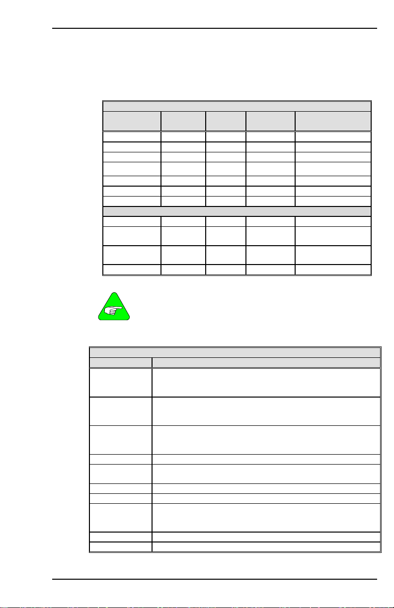
Danaher Motion 09/05 VARIABLE AND COMMAND LIST
MENCTYPE
Sets the motor encoder type. When this variable is changed on an
encoder-based system, the drive enters a no-comp state, requiring a
CONFIG command (see CONFIG). In version 1 firmware prior to 1.2.0,
MENCTYPE=0 is assumed. This variable may take value from 0 to 9.
DIGITAL ENCODER OPTIONS
MENCTYPE
0
1
2
3
4
5
6
0
7
8
MENCTYPE Method of Initialization
9
MENCTYPE 0 can be used with both the Digital and Sine
option. The drive automatically senses the Sine Encoder
board and make the appropriate adjustments.
All MENCTYPEs applicable for incremental encoders are
NOTE
applicable for sine encoders. This also includes the "wakeand-shake" initialization.
0
1
2
3
4
5 Halls only (version 4.1.8 and higher).
6 Initialization is automatic upon power-up.
7
8 Initialization is automatic upon power-up.
9 Initialization is automatic upon power-up.
A/B
quad
X X X All
X X All
X X All
X All
X All
X X All
X X X 3.4.0 and later
X X
X
X Endat 3.4.0 and later
Initialization is automatic upon power-up. Marker pulse
location may be performed using ENCINIT to locate the
marker.
Initialization is required and is triggered by the ENCSTART
command. This may optionally be followed by marker pulse
location usingENCINIT.
Initialization is required and is triggered on power up (on drive
enable) or by using ENCSTART. This may optionally be
followed by marker pulse location using ENCINIT.
Initialization is required and is triggered by ENCSTART.
Initialization is required and is triggered on power up (when
the drive is enabled) or by using ENCSTART.
Initialization is automatic upon power-up. Marker pulse
location may be performed using ENCINIT to locate the
marker.
Marker
Pulse
X 4.1.8 and later
SINE ENCODER OPTIONS
INITIALIZATION METHODS
Hall
Effects
C/D
Channels
C/D
Channels
Firmware
Versions
3.4.0 and later
3.4.0 and later
VarCom Reference M-SS-017-04 Rev. M 55
Page 64

VARIABLE AND COMMAND LIST 09/05 Danaher Motion
NOTE
Firmware Versions: All Type: switch mode (R/W)
Range: 0 to 9 Default: motor data (0 if undefined)
Opmodes: All Units: N/A
Drive Status: DIS EEPROM: Yes
All initializations above are completely automatic when using
standard Kollmorgen motors.
For MENCTYPE 0-2 and 7, perform ENCINIT where MENCOFF
is unknown.
MFBDIR
Sets the motor feedback direction. This switch is used during the
autoconfig process (ACONFIG). If Phase 5 of autoconfig (direction test)
fails, use MFBDIR to switch the motor feedback direction. The range is:
MFBDIR = 0: normal commutation direction, normal velocity direction.
MFBDIR = 1: inverted commutation direction, normal velocity direction.
MFBDIR = 2: normal commutation direction, inverted velocity direction.
MFBDIR = 3: inverted commutation direction, inverted velocity direction.
If the motor leads/motor stator are phased incorrectly, setting
MFBDIR=1 solves the problem. If the feedback device is
connected/phased incorrectly, you have to set MFBDIR=3, which
changes both the commutation and velocity loop directions.
Firmware Versions: 3.3.0 and later Type: switch mode (R/W)
Range: 0 to 3 Default: 0
Opmodes: All Drive Status: DIS
Units: N/A EEPROM: Yes
MFOLD
Displays the status of the motor foldback circuit. When the system
current level exceeds MICONT for too long, the drive enters motor
foldback mode, MFOLD changes from 0 to 1, and the drive current is
limited gradually (in exponential fashion) to the value of MICONT. See
also FOLD, FOLDMODE, MFOLDD, MFOLDDIS, MFOLDR, AND
MFOLDT.
0 = motor foldback OFF (inactive)
1 = motor foldback ON (drive is limiting output current)
Firmware Versions: 3.2.0 and later Type: switch (R)
Range: 0, 1 Default: 0
Opmodes: All Drive Status: EN/DIS
Units: N/A EEPROM: No
56 M-SS-017-04 Rev. M VarCom Reference
Page 65

Danaher Motion 09/05 VARIABLE AND COMMAND LIST
MFOLDD
Sets the delay time for motor foldback. This is the amount of time that
the system current can exceed MICONT before the drive enters the
motor foldback state. The time units assume a worst-case scenario
where the drive is applying MIPEAK current. A current level of less than
MIPEAK can be allowed for a longer time. See FOLD, FOLDMODE,
MFOLD, MFOLDDIS, MFOLDR, and MFOLDT.
Firmware Versions: 3.2.0 and later Type: variable (R/W)
Range: 1 to 2400 Default: 1200
Opmodes: All Drive Status: EN/DIS
Units: seconds at MIPEAK EEPROM: Yes
MFOLDDIS
Enables/disables the motor current foldback function. See FOLD,
FOLDMODE, MFOLD, MFOLDD, MFOLDR, and MFOLDT.
0 = enable motor foldback function
1 = disable motor foldback function
Firmware Versions: 3.2.0 and later Type: switch (R/W)
Range: 0, 1 Default: 1 (disabled)
Opmodes: All Drive Status: EN/DIS
Units: N/A EEPROM: Yes
MFOLDR
Sets the recovery time for motor foldback. After the drive enters the
motor foldback state (MFOLD=1), and the current folds back to
MICONT, this is the amount of time that the current is held at MICONT
or below before it is allowed to exceed MICONT again. See FOLD,
FOLDMODE, MFOLD, MFOLDD, MFOLDDIS, and MFOLDT.
Firmware Versions: 3.2.0 and later Type: variable (R/W)
Range: 900 to 3600 Default: 1800
Opmodes: All Drive Status: EN/DIS
Units: seconds EEPROM: Yes
MFOLDT
Sets the time constant for motor foldback. After the drive enters the
motor foldback state (MFOLD=1), this variable defines how long it takes
the drive to reduce the system current level to MICONT. See FOLD,
FOLDMODE, MFOLD, MFOLDD, MFOLDDIS, and MFOLDR.
Firmware Versions: 3.2.0 and later Type: variable (R/W)
Range: 1 to 1200 Default: 600
Opmodes: All Drive Status: EN/DIS
Units: seconds EEPROM: Yes
VarCom Reference M-SS-017-04 Rev. M 57
Page 66

VARIABLE AND COMMAND LIST 09/05 Danaher Motion
MH
This command (Move Home) causes the motor to move to the home
position. HOMESPD controls the speed. HOMETYPE defines the type
of homing sequence, while HOMESTATE gives the homing status and
describes the homing process further.
After power up, or after a feedback loss fault, the first issue of this
command causes a search for home. Further issues of this command
causes a move to home position (equivalent to MA 0 command).
HOMESPD controls the speed and direction of the search. PFB is
normalized to 0 after completion.
The optional flag [in pos ack] enables you to direct the drive to indicate
when the commanded MOVE is completed. When this flag is set to 1,
the drive, upon completion of the commanded MOVE, outputs an
exclamation point (!) over the serial port. The exclamation point is tied to
the STOPPED flag and is issued when STOPPED transitions from 0 to
1.
Homing Process Using MH command:
– Issue MH via serial port
– If home switch is already pressed (see IN1MODE = 10). The drive moves in
the opposite homing direction, until home switch is released.
– If home switch is not already pressed, the drive move in the homing
direction, until home switch is pressed.
– Drive captures position of first index (or resolver 0) past switch.
– Drive decelerates to stop using DEC.
– Drive goes back to home position using ACC, DEC, and HOMESPD (in
firmware versions 3.3.0 and later, the speed is MISPEED0). Drive resets the
absolute position (PFB) to 0.
Homing Process using digital I/O (see descriptions for INx, and
INxMODE for INxMODE 10 and 12):
When Home Input is activated for the first time after power-up:
– If home switch is already pressed (see INxMODE 10), the drive
moves in the opposite homing direction, until home switch is
released.
– If home switch is not already pressed, drive moves in the homing
direction, until home switch is pressed.
– Drive captures position of first index (or resolver 0) past switch.
– Drive decelerates at DEC to stop.
– Drive goes back to home position using ACC, DEC, and HOMESPD
(in firmware versions 3.3.0 and later, the speed is MISPEED0).
– Drive resets the absolute position (PFB) to 0
Otherwise:
Drive moves to absolute 0 at HOMESPD.
in pos ack = 0: do not indicate when move is complete
in pos ack = 1: indicate when move is complete
Firmware Versions: 3.1.0 and later Command Syntax: MH [in pos ack]
Opmodes: 8
Drive Status: EN
Range: [in pos ack] 0 or 1 (optional)
58 M-SS-017-04 Rev. M VarCom Reference
Page 67

Danaher Motion 09/05 VARIABLE AND COMMAND LIST
MHINVA
MHINVA applies to encoder-based systems which use hall switches to
commutate. This variable inverts the hall sensor A feedback, causing
the system to read the A hall channel as inverted data.
MHINVA = 0: do not invert hall A
MHINVA = 1: invert hall A
Firmware Versions: All Type: switch (R/W)
Range: 0, 1 Default: 0
Opmodes: All Drive Status: DIS
Units: N/A EEPROM: Yes
MHINVB
MHINVB applies to encoder-based systems which use hall switches to
commutate. This variable inverts the hall sensor B feedback, causing
the system to read the B hall channel as inverted data.
MHINVB = 0: do not invert hall B
MHINVB = 1: invert hall B
Firmware Versions: All Type: switch (R/W)
Range: 0, 1 Default: 0
Opmodes: All Drive Status: DIS
Units: N/A EEPROM: Yes
MHINVC
MHINVC applies to encoder-based systems which use hall switches to
commutate. This variable inverts the hall sensor C feedback, causing
the system to read the C hall channel as inverted data.
MHINVC = 0: do not invert hall C
MHINVC = 1: invert hall C
Firmware Versions: All Type: switch (R/W)
Range: 0, 1 Default: 0
Opmodes: All Drive Status: DIS
Units: N/A EEPROM: Yes
MI
MI (serial Move Incremental) incrementally moves the specified distance
at the specified speed. A positive incremental move occurs in the
direction determined by the variable DIR, and a negative incremental
move occurs in the opposite direction.
[in pos ack] enables the operator to direct the drive to indicate when the
commanded move is completed. When this flag is set to 1, the drive,
upon completion of the commanded move, outputs an exclamation point
(!) over the serial port. The exclamation point is tied to the STOPPED
flag and is issued when STOPPED transitions from 0 to 1.
VarCom Reference M-SS-017-04 Rev. M 59
Page 68

VARIABLE AND COMMAND LIST 09/05 Danaher Motion
Position is in feedback counts. Issuing MI while the motor is not stopped
causes the command to be buffered for later execution. No more than
one command is buffered. <velocity> is always given in rpm or mm/sec
and is not affected by units. See INPOS, MA, PCMD, PEINPOS, PFB,
and STOPPED.
in pos ack = 0: do not indicate when move is complete
in pos ack = 1: indicate when move is complete
Firmware Versions: 3.1.0 and later
Command Syntax: MI <pos> <vel> [in pos ack]
Opmodes: 8 Drive Status: EN
Range: <pos> LONG to LONG (feedback counts)
Example:
MI 10000 1000 (move 10,000 counts in the positive direction at a speed of
MI -10000 100 1 (move 10,000 counts in the negative direction at a speed of
NOTE
<vel> 1 to VMAX (rpm or mm/sec)
[in pos ack] 0 or 1 (optional)
1,000 rpm)
100 rpm; transmit a (!) to the serial port when the move is
complete)
For very slow moves, set VLIM as low as possible before
setting <velocity> less than 1 in MA and MI. This can only be
set in firmware version 3.7.0 and higher.
MICONT
Sets the motor’s continuous rated current. When this variable is
changed, the drive enters a no-comp state, requiring a CONFIG .
Firmware Versions: All Type: variable (R/W)
Range: 1 to 1750 Default: motor data
Opmodes: All Drive Status: DIS
Units: amps
*0.1 EEPROM: Yes
RMS
MIDIST0
MIDIST0, with MIDIST1, MIDIST2, and MIDIST3, set four possible index
distances for triggering via a digital input (IN1, IN2, or IN3) set to
INxMODE 7. The other two inputs must be configured to INxMODE 14
and 15.
Selects an MIDISTx/MISPEEDx pair using two digital inputs configured
to INxMODEs 14 and 15. An incremental move (MI) is triggered for the
selected distance and speed by configuring the third digital input to
INxMODE=7 and transitioning that input from low to high. When the
INxMODE input goes high, the move is initiated.
Position is in counts, where 65536 counts represent one motor
revolution for resolver systems, and 4*MENCRES counts represents on
motor revolution for encoder systems. See MISPEED0.
Firmware Versions: 3.1.0 and later Type: variable (R/W)
Range: -2,147,483,647 to +2,147,483,647 Default: 0
Opmodes: 8 Drive Status: EN/DIS
Units: counts EEPROM: Yes
60 M-SS-017-04 Rev. M VarCom Reference
Page 69

Danaher Motion 09/05 VARIABLE AND COMMAND LIST
MIDIST1
MIDIST1, with MIDIST0, MIDIST2, and MIDIST3, set four possible index
distances for triggering via a digital input (IN1, IN2, or IN3) set to
INxMODE 7. The other two inputs must be configured to INxMODE 14
and 15.
Select an MIDISTx/MISPEEDx pair using two digital inputs configured to
INxMODEs 14 and 15. An incremental move (MI) is triggered for the
selected distance and speed by configuring the third digital input to
INxMODE=7 and transitioning that input from low to high. When the
INxMODE input goes high, the move is initiated.
Position is in counts, where 65536 counts represent one motor
revolution for resolver systems, and 4*MENCRES counts represents on
motor revolution for encoder systems. See MISPEED1.
Firmware Versions: 3.1.0 and later Type: variable (R/W)
Range: -2,147,483,647 to +2,147,483,647 Default: 0
Opmodes: 8 Drive Status: EN/DIS
Units: counts EEPROM: Yes
MIDIST2
MIDIST2, with MIDIST0, MIDIST1, and MIDIST3, set four possible index
distances for triggering via a digital input (IN1, IN2, or IN3) set to
INxMODE 7. The other two inputs must be configured to INxMODE 14
and 15.
Select an MIDISTx/MISPEEDx pair using two digital inputs configured to
INxMODEs 14 and 15. An incremental move (MI) is triggered for the
selected distance and speed by configuring the third digital input to
INxMODE=7 and transitioning that input from low to high. When the
INxMODE input goes high, the move is initiated.
Position is in counts, where 65536 counts represent one motor
revolution for resolver systems, and 4*MENCRES counts represents on
motor revolution for encoder systems. See MISPEED2.
Firmware Versions: 3.1.0 and later Type: variable (R/W)
Range: -2,147,483,647 to +2,147,483,647 Default: 0
Opmodes: 8 Drive Status: EN/DIS
Units: counts EEPROM: Yes
MIDIST3
MIDIST3, with MIDIST0, MIDIST1, and MIDIST2, set four possible index
distances for triggering via a digital input (IN1, IN2, or IN3) set to
INxMODE 7. The other two inputs must be configured to INxMODE 14
and 15.
Select an MIDISTx/MISPEEDx pair using two digital inputs configured to
INxMODEs 14 and 15. An incremental move (MI) is triggered for the
selected distance and speed by configuring the third digital input to
INxMODE=7 and transitioning that input from low to high. When the
INxMODE input goes high, the move is initiated.
VarCom Reference M-SS-017-04 Rev. M 61
Page 70

VARIABLE AND COMMAND LIST 09/05 Danaher Motion
Position is in counts, where 65536 counts represent one motor
revolution for resolver systems, and 4*MENCRES counts represents on
motor revolution for encoder systems. See MISPEED3
Firmware Versions: 3.1.0 and later Type: variable (R/W)
Range: -2,147,483,647 to +2,147,483,647 Default: 0
Opmodes: 8 Drive Status: EN/DIS
Units: counts EEPROM: Yes
MIPEAK
Sets the motor’s peak rated current. When this variable changes, the
drive enters a no-comp state, requiring a CONFIG.
Firmware Versions: All Type: variable (R/W)
Range: 3 to 3500 Default: motor data
Opmodes: All Drive Status: DIS
Units: amps
*0.1 EEPROM: Yes
RMS
MISPEED0
MISPEED0, with MISPEED1, MISPEED2, and MISPEED3, set four
possible index speeds for triggering via a digital input (IN1, IN2, or IN3)
set to INxMODE 7. The other two inputs must be configured to
INxMODE 14 and 15.
Opmode 8 allows you to select an MIDIST0 / MISPEED0 pair using two
digital inputs that are configured to INxMODEs 14 and 15. An
incremental move (MI) is then triggered for the selected distance and
speed by configuring the third digital input to INxMODE=7 and setting
that input high. When the INxMODE input goes high, the move is
initiated.
In firmware versions 3.3.0 and later, when homing is
performed (MH, HOMESPD, HOMESTATE, and HOMETYPE),
MISPEED0 sets the velocity at which the drive returns to
NOTE
Opmode 1 allows you to select a MISPEED0 velocity using two digital
inputs configured to INxMODEs 14 and 15. A JOG is then triggered for
the selected speed by configuring the third digital input to INxMODE=7
and setting that input high. When the INxMODE input is high, JOG is
issued, and when the INxMODE input is low, the JOG is not performed.
home after finding home.
PROFMODE affects JOG in this scenario. If you select
MISPEED0 and set MISPEED0=0, an analog input JOG can
be given, as is normal for OPMODE 1 operation.
62 M-SS-017-04 Rev. M VarCom Reference
NOTE
Firmware Versions: 3.1.0 and later Type: variable (R/W)
Range: -VLIM to +VLIM Default: 100
Opmodes: 1,8 Drive Status: EN/DIS
linear: mm/sec
EEPROM: Yes Units: rotary: rpm
Page 71

Danaher Motion 09/05 VARIABLE AND COMMAND LIST
MISPEED1
MISPEED1, with MISPEED0, MISPEED2, and MISPEED3, set four
possible index speeds for triggering via a digital input (IN1, IN2, or IN3)
set to INxMODE 7. The other two inputs must be configured to
INxMODE 14 and 15.
Opmode 8 allows you to select an MIDIST0 / MISPEED0 pair using two
digital inputs that are configured to INxMODEs 14 and 15. An
incremental move (MI) is then triggered for the selected distance and
speed by configuring the third digital input to INxMODE=7 and setting
that input high. When the INxMODE input goes high, the move is
initiated.
In firmware versions 3.3.0 and later, when homing is
performed (MH, HOMESPD, HOMESTATE, and HOMETYPE),
MISPEED0 sets the velocity at which the drive returns to
NOTE
Opmode 1 allows you to select a MISPEED0 velocity using two digital
inputs configured to INxMODEs 14 and 15. A JOG is then triggered for
the selected speed by configuring the third digital input to INxMODE=7
and setting that input high. When the INxMODE input is high, JOG is
issued, and when the INxMODE input is low, the JOG is not performed.
NOTE
Firmware Versions: 3.1.0 and later Type: variable (R/W)
Range: -VLIM to +VLIM Default: 100
Opmodes: 1,8 Drive Status: EN/DIS
Units: rotary: rpm EEPROM: Yes
home after finding home.
PROFMODE affects JOG in this scenario. If you select
MISPEED0 and set MISPEED0=0, an analog input JOG can
be given, as is normal for OPMODE 1 operation.
linear: mm/sec
MISPEED2
MISPEED2, with MISPEED0, MISPEED1, and MISPEED3, set four
possible index speeds for triggering via a digital input (IN1, IN2, or IN3)
set to INxMODE 7. The other two inputs must be configured to
INxMODE 14 and 15.
Opmode 8 allows you to select an MIDIST0 / MISPEED0 pair using two
digital inputs that are configured to INxMODEs 14 and 15. An
incremental move (MI) is then triggered for the selected distance and
speed by configuring the third digital input to INxMODE=7 and setting
that input high. When the INxMODE input goes high, the move is
initiated.
In firmware versions 3.3.0 and later, when homing is
performed (MH, HOMESPD, HOMESTATE, and HOMETYPE),
MISPEED0 sets the velocity at which the drive returns to
NOTE
VarCom Reference M-SS-017-04 Rev. M 63
home after finding home.
Page 72

VARIABLE AND COMMAND LIST 09/05 Danaher Motion
Opmode 1 allows you to select a MISPEED0 velocity using two digital
inputs configured to INxMODEs 14 and 15. A JOG is then triggered for
the selected speed by configuring the third digital input to INxMODE=7
and setting that input high. When the INxMODE input is high, JOG is
issued, and when the INxMODE input is low, the JOG is not performed.
PROFMODE affects JOG in this scenario. If you select
MISPEED0 and set MISPEED0=0, an analog input JOG can
be given, as is normal for OPMODE 1 operation.
NOTE
Firmware Versions: 3.1.0 and later Type: variable (R/W)
Range: -VLIM to +VLIM Default: 100
Opmodes: 1,8 Drive Status: EN/DIS
Units: rotary: rpm EEPROM: Yes
linear: mm/sec
MISPEED3
MISPEED3, with MISPEED0, MISPEED1, and MISPEED2, set four
possible index speeds for triggering via a digital input (IN1, IN2, or IN3)
set to INxMODE 7. The other two inputs must be configured to
INxMODE 14 and 15.
Opmode 8 allows you to select an MIDIST0 / MISPEED0 pair using two
digital inputs that are configured to INxMODEs 14 and 15. An
incremental move (MI) is then triggered for the selected distance and
speed by configuring the third digital input to INxMODE=7 and setting
that input high. When the INxMODE input goes high, the move is
initiated.
In firmware versions 3.3.0 and later, when homing is
performed (MH, HOMESPD, HOMESTATE, and HOMETYPE),
MISPEED0 sets the velocity at which the drive returns to
NOTE
Opmode 1 allows you to select a MISPEED0 velocity using two digital
inputs configured to INxMODEs 14 and 15. A JOG is then triggered for
the selected speed by configuring the third digital input to INxMODE=7
and setting that input high. When the INxMODE input is high, JOG is
issued, and when the INxMODE input is low, the JOG is not performed.
home after finding home.
PROFMODE affects JOG in this scenario. If you select
MISPEED0 and set MISPEED0=0, an analog input JOG can
be given, as is normal for OPMODE 1 operation.
64 M-SS-017-04 Rev. M VarCom Reference
NOTE
Firmware Versions: 3.1.0 and later Type: variable (R/W)
Range: -VLIM to +VLIM Default: 100
Opmodes: 1,8 Drive Status: EN/DIS
Units: rotary: rpm EEPROM: Yes
linear: mm/sec
Page 73

Danaher Motion 09/05 VARIABLE AND COMMAND LIST
MJ
Sets the motor’s rotor inertia (rotary motors) or motor coil mass (linear
motors, MOTORTYPE=2). The Motor Rotor Inertia (MJ) and the Load
Moment of Inertia Ratio (LMJR) define the total system moment of
inertia. LMJR, MJ and the required closed loop bandwidth (BW) are
used for the Velocity Control Loop design in the Standard PolePlacement controller (COMPMODE = 2 or 4).
Firmware Versions: All Type: variable (R/W)
Range: 1 to 2,000,000,000 Default: motor data
Opmodes: All Drive Status: DIS
Units: rotary: Kg *m
linear: grams
2
*10
-6
EEPROM: Yes
MLGAINC
Sets the current loop adaptive gain value at continuous motor current
(MICONT). MLGAINC, MLGAINP, and MLGAINZ define the adaptive
gain algorithm that is based on motor current.
The current-based adaptive gain algorithm is a gain calculation method
that increases current loop stability by reducing the current loop gain as
the motor current increases. The current-based adaptive gain algorithm
is set up by defining the gains at peak motor current (MLGAINP), at
continuous motor current (MLGAINC), and at zero motor current
(MLGAINZ). All other gains between zero, continuous, and peak current
are interpolated linearly.
MLGAINC is typically set to the midpoint of MLGAINZ and MLGAINP.
When this variable changes, the drive enters a no-comp state, requiring
a CONFIG.
Firmware Versions: All Type: variable (R/W)
Range: 1 to 100 Default: 8
Opmodes: All Drive Status: DIS
Units: % *10 EEPROM: Yes
MLGAINP
Sets the current loop adaptive gain value at peak motor current
(MIPEAK). MLGAINC, MLGAINP, and MLGAINZ define the adaptive
gain algorithm that is based on motor current.
The current-based adaptive gain algorithm is a gain calculation method
that increases current loop stability by reducing the current loop gain as
the motor current increases. The current-based adaptive gain algorithm
is set up by defining the gains at peak motor current (MLGAINP), at
continuous motor current (MLGAINC), and at zero motor current
(MLGAINZ). All other gains between zero, continuous, and peak current
are interpolated linearly.
VarCom Reference M-SS-017-04 Rev. M 65
Page 74

VARIABLE AND COMMAND LIST 09/05 Danaher Motion
MLGAINP is typically set to 4 for motors that do not have a lot of iron in
their construction and peak currents within the boundaries of the drive. If
the motor is rated for much more than what the drive can deliver or if
there is a lot of iron in the motor, saturation has less of an effect, and
there may be an opportunity to increase this variable. The range for this
variable is typically 4 to 7. When this variable is changed, the drive
enters a no-comp state, requiring a CONFIG.
Firmware Versions: All Type: variable (R/W)
Range: 1 to 100 Default: 4
Opmodes: All Drive Status: DIS
Units: % *10 EEPROM: Yes
MLGAINZ
Set MLGAINZ to 10 as it performs no function.
Firmware Versions: All Type: variable (R/W)
Range: 1 10 Default: 10
Opmodes: All Drive Status: DIS
Units: % *10 EEPROM: Yes
MLIST
Dumps all motor variables and their values to the serial port.
Firmware Versions: All Command Syntax: MLIST
Opmodes: All Drive Status: EN/DIS
MLMIN
Sets the motor’s minimum line-to-line inductance. This variable
is used for current loop controller design and as an input to the
Torque Angle Control algorithms. When this variable is changed,
the drive enters a no-comp state, requiring a CONFIG.
Firmware Versions: All Type: variable (R/W)
Range: 1 to 32767 Default: motor data
Opmodes: All Drive Status: DIS
Units: millihenries *10 –2 EEPROM: Yes
MODMODE
Causes the rotary mode to be enabled. See the Rotary Mode
Application Note for further details.
0 = disabled
1 = enabled
Firmware Versions: 3.6.4 and higher Type: switch (R/W)
Range: 0, 1 Default: 0
Opmodes: 8 Drive Status: EN/DIS
Units: N/A EEPROM: Yes
66 M-SS-017-04 Rev. M VarCom Reference
Page 75

Danaher Motion 09/05 VARIABLE AND COMMAND LIST
MOTOR
MOTOR is the name of the motor connected to the drive. The motor
string variable MUST BE PRECEDED BY DOUBLE QUOTES (“) when
entered.
Firmware Versions: All Type: string variable (R/W)
Range: 10 characters Default: motor data
Opmodes: All Drive Status: EN/DIS
Units: N/A EEPROM: Yes
MOTORTYPE
Sets the drive's communication and user unit settings for different motor
types as follows:
MOTORTYPE=0: permanent magnet rotary motor with legacy
resolver and encoder alignment
MOTORTYPE=1: reserved; do not use
MOTORTYPE=2: permanent magnet linear motor which converts
units to linear
MOTORTYPE=3: permament magnet rotary motor with resolver and
encoder alignment for all AKM motors (version
7.0.0 and higher and MOTIONLINK 3.4.0 and
Firmware Versions: 2.1.0 and later Type: switch mode (R/W)
Range: 0 to 3 Default: 0 automatically set as part
Opmodes: All Drive Status: DIS
Units: N/A EEPROM: Yes
higher)
of comp file loading
MPHASE
Defines the resolver or encoder phase relative to the standard
commutation table. This variable is used to compensate for resolver
offset and should be set to 0, if there is no resolver offset.
Changing MPHASE does not change the value of PRD or
HWPOS, nor does it create a physical change in the position
of the motor shaft - it merely shifts the internal commutation
table.
NOTE
Firmware Versions: All Type: variable (R/W)
Range: 0 to 359 Default: motor data
Opmodes: All Drive Status: DIS
Units: Feedback device electrical degrees EEPROM: Yes
MPITCH
MPITCH is for use with linear motors (MOTORTYPE = 2). It defines the
pole-pitch (length in millimeters of one electrical cycle - 360 electrical
degrees) of the motor and allows the drive to calculate other variables
(such as velocity). The drive assumes a no-comp state after an entry of
this parameter and requires a CONFIG.
Firmware Versions: 2.1.0 and later Type: variable (R/W)
Range: 1 to 500 Default: 16
Opmodes: All Drive Status: DIS
Units: mm per 360 electrical degrees EEPROM: Yes
VarCom Reference M-SS-017-04 Rev. M 67
Page 76

VARIABLE AND COMMAND LIST 09/05 Danaher Motion
MPOLES
Sets the number of motor poles. This variable is used for commutation
control and represents the number of individual magnetic poles of the
motor (not pole pairs). When this variable is changed, the drive enters a
no-comp state, requiring a CONFIG. When MOTORTYPE=2, this
variable is forced to a value of 2.
Firmware Versions: All Type: switch mode (R/W)
Range: 2, 4, 6, 8, .... , 78,80 Default: motor data
Opmodes: All Drive Status: DIS
Units: poles EEPROM: Yes
MRESPOLES
Sets the number of individual poles in the feedback device. This variable
is used for the commutation function, as well as for velocity feedback
scaling and represents the number of individual poles, not pole pairs.
When this variable is changed on a resolver system, the drive enters a
no-comp state, requiring a CONFIG.
Firmware Versions: All Type: switch mode (R/W)
Range: 2, 4, 6, 8, 12, 14, 16, …. 64 (resolver-based)
Default: motor data Opmodes: All
Units: poles EEPROM: Yes
Drive Status: DIS
0, 2, 4, 6, 8, 12, 14, 16, …. 64 (encoder-based)
MSG
Enables and disables the sending of error messages from the drive to
the serial port.
0 = disable messages
1 = enable messages
MSG = 1 is needed for proper operation of MOTIONLINK.
68 M-SS-017-04 Rev. M VarCom Reference
NOTE
Firmware Versions: All Type: switch (R/W)
Range: 0, 1 Default: 1
Opmodes: All Drive Status: EN/DIS
Units: N/A EEPROM: Yes
Page 77

Danaher Motion 09/05 VARIABLE AND COMMAND LIST
MSININT
MSININT is used with the sine encoder option and sets the interpolation
level of the CB drive used with sine encoders. Actual resolution is 4x this
number. For example, MSINIT 256 with MENCRES 2048 results in a
system resolution of 21 bits or 2,097,152 counts per revolution.
Firmware Versions: 3.2.0
(3.3.0 or higher variable is automatically set to 256)
Range: 1, 2, 4, 8, 16, 32, 64,128,256
CD Series 5 allows 512 and 1024
Type: switch mode (R/W) Default: 256
Units: bits EEPROM: Yes
Drive Status: DIS
(Endat encoders in 3.4 firmware)
256 only (for all other sine encoders)
Opmodes: All
MSINFRQ
MSINFRQ is used with the sine encoder option and sets the maximum
frequency limit of the encoder equivalent output. If the encoder
equivalent output exceeds the value set by this variable, it becomes
inaccurate and a burst overflow fault is generated.
0 = ignore burst overflow fault
1 = 2.5 MHz
2 = 1.25 MHz
3 = 625 kHz
4 = 312 kHz
Firmware Versions: 3.3.0 and higher Type: switch mode (R/W)
Range: 0 to 4 Default: 1
Opmodes: All Drive Status: DIS
Units: N/A EEPROM: Yes
MSPEED
Defines the maximum recommended velocity of the motor. When this
variable is changed the drive enters a no-comp state requiring a
CONFIG.
Firmware Versions: All Type: variable (R/W)
Range: 10 to 32767 Default: motor data
Opmodes: All Drive Status: DIS
linear: mm/sec
EEPROM: Yes Units: rotary: rpm
MTANGLC
Sets the value of the torque-related commutation angle advance at the
motor’s continuous current rating (MICONT). This variable helps
increase reluctance torque. For surface magnet motors, a typical value
is 5. For motors with embedded magnets, a typical value is 8 to 10.
Firmware Versions: All Type: variable (R/W)
Range: 0 to 45 Default: 10
Opmodes: All Drive Status: EN/DIS
Units: electrical degrees EEPROM: Yes
VarCom Reference M-SS-017-04 Rev. M 69
Page 78

VARIABLE AND COMMAND LIST 09/05 Danaher Motion
MTANGLP
Sets the value of the torque-related commutation angle advance at the
motor’s peak current (MIPEAK). This variable helps increase reluctance
torque. For surface magnet motors, a typical value is 10. For motors
with embedded magnets, a typical value is 23 to 25.
Firmware Versions: All Type: variable (R/W)
Range: 0 to 45 Default: 23
Opmodes: All Drive Status: EN/DIS
Units: electrical degrees EEPROM: Yes
MVANGLF
Sets the value of the velocity-related commutation angle advance to be
used when the motor is operating at motor max speed (MSPEED).
Between MSPEED/2 rpm and MSPEED, the angle advance is linearly
interpolated based on MVANGLH and MVANGLF.
When a CLREEPROM is issued, MVANGLF is set to a value of 10. If a
CONFIG is then issued, MVANGLF is set to a default value based on
MSPEED and MPOLES. Once you enter a value for MVANGLF, it
keeps that value and is not changed if a CONFIG is executed.
Firmware Versions: All Type: variable (R/W)
Range: 0 to 90 Default: calculated for motor data
Opmodes: All Drive Status: EN/DIS
Units: electrical degrees EEPROM: Yes
MVANGLH
Sets the value of the velocity-related commutation angle advance to be
used when the motor is operating at half of the motor max speed
(MSPEED). Between 0 rpm and half of MSPEED, the angle advance is
linearly interpolated based on MVANGLH.
When a CLREEPROM is issued, MVANGLH is set to a value of 5. If a
CONFIG is then issued, MVANGLH is set to a default value based on
MSPEED and MPOLES. Once you enter a value for MVANGLH, it
keeps that value and is not changed if a CONFIG is executed.
Firmware Versions: All Type: variable (R/W)
Range: 0 to 90 Default: calculated for motor data
Opmodes: All Drive Status: EN/DIS
Units: electrical degrees EEPROM: Yes
NOTCHBW
Sets the bandwidth of the notch filter used in the velocity loop. Affects
the system only when FILTMODE=3.
Firmware Versions: 3.1.0 and later Type: variable (R/W)
Range: 1 to 100 Default: 1
Opmodes: All Drive Status: EN/DIS
Units: Hz EEPROM: Yes
70 M-SS-017-04 Rev. M VarCom Reference
Page 79

Danaher Motion 09/05 VARIABLE AND COMMAND LIST
NOTCHHZ
Sets the center frequency of the notch filter used in the velocity loop.
Affects the system only when FILTMODE=3.
Firmware Versions: 3.1.0 and later Type: variable (R/W)
Range: 30 to 1000 Default: 500
Opmodes: All Drive Status: EN/DIS
Units: Hz EEPROM: Yes
O1
O1 is used to read or write the state of the hardware output on user
connector C3 Pin 12. See O1MODE.
0 = OFF
1 = ON
Writing O1 in certain O1MODE conditions does not stop
the drive from resetting the output according to drive
conditions.
NOTE
Firmware Versions: 2.1.0 and later Type: switch (R/W)
Range: 0, 1 Default: N/A
Opmodes: All Drive Status: EN/DIS
Units: N/A EEPROM: N/A
O1MODE UCB1 CD SERIES 2
A switch mode variable used to define the function of O1:
0 - Disabled
1 - O1 goes on when absolute motor speed is above 01TRIG
speed.
2 - O1 goes on when the absolute actual output current is above
O1TRIG current.
3 - O1 goes on when drive is in FOLDBACK.
4 - O1 goes on when absolute motor speed is above O1TRIG but
less than O1RST.
5 - Brake Mode: O1 is OFF only when (1) drive is disabled or (2)
during an active disable sequence, when actual motor speed
has dropped below DISSPEED, but DISTIME timer has not
timed out yet. O1 is ON when the drive is enabled.
6 - Motion Complete Output: O1 is tied to STOPPED switch.
7 - In Position Output: O1 is tied to INPOS.
8 - Zero Speed Detect: O1 on if absolute motor speed <O1TRIG.
9 - Programmable Limit Switch: O1 goes on if
O1TRIG<PFB<O1RST (firmware versions 3.2.0 and later). If
O1MODE=9, the range of O1TRIG and O1RST is 0 to
2147483647. Trying to write a negative value to 01TRIG or
01RST results in an error (out of range) message. When
O1MODE=9, the output is active if O1TRIG< abs(Motor
Position Feedback)<O1RST. The absolute value of PFB is
used.
VarCom Reference M-SS-017-04 Rev. M 71
Page 80

VARIABLE AND COMMAND LIST 09/05 Danaher Motion
10 - Active: O1 goes on if drive is active (firmware versions 3.1.0
and later).
11 - O1 is 1 after initialization is completed or when the
commutation is aligned to the motor. In resolver based
systems the output is always 1 if there is no feedback loss
fault.
12 - The output is active when the SERCOS ring is broken and
the drive does not receive data. The output is inactive when
the SERCOS telegrams are received by the drive (firmware
version 4.1.4 and later).
O1 at 0 indicates if encoder initialization is incomplete or
feedback loss is detected.
NOTE
Firmware Versions: 2.1.0 and later Type: switch mode (R/W)
Range: 0 to 12 Default: 6
Opmodes: All Drive Status: EN/DIS
Units: Hz EEPROM: Yes
O1MODE UCB2 CD SERIES 5
Firmware version 6.6.0 25/Sep/03:
O1MODE=0 – O1 is controlled directly by O1.
O1MODE=1 – O1 is on when Motor Speed > O1TRIG.
O1MODE=2 – O1 is on when the equivalent current (‘I’) is greater
than O1TRIG.
O1MODE=3 – O1 is on during foldback state.
O1MODE=4 – O1 is on when O1TRIG < Motor Speed < O1RST.
O1MODE=5 – brakes control.
O1MODE=6 – O1 is on when motion completed (STOPPED bit is
set).
O1MODE=7 – O1 is on when IN POSITION bit is set.
O1MODE=8 – O1 is on when Motor Speed < O1TRIG.
O1MODE=9 – O1 is on when O1TRIG < abs(Motor Position
Feedback) < O1RST.
O1MODE=10 – O1 is on when the drive is enabled (ACTIVE=1).
O1MODE=11 – O1 goes high when Encoder init was done and low
again in the beginning of an Encoder init process.
O1MODE=12 – O1 goes high when SERCOS break is detected
and low again when SERCOS communication
functions well.
O1MODE=13 – O1 is on when PFB burst is transmitted via the
encoder simulation output.
72 M-SS-017-04 Rev. M VarCom Reference
Page 81

Danaher Motion 09/05 VARIABLE AND COMMAND LIST
O1RST
A variable used to define the reset level for O1MODE. Range is
dependent on O1MODE:
0 - N/A
1 - N/A
2 - N/A
3 - N/A
4 - Absolute: 0 - 15000 rpm (0 - 250*MPITCH mm/sec for linear)
5 - Absolute: 0 - 15000 rpm (0 - 250*MPITCH mm/sec for linear)
6 - N/A
7 - N/A
8 - N/A
9 – Refer to O1MODE=9
10 - N/A
Firmware Versions: 2.1.0 and later Type: variable (R/W)
Range: 0 to 10 (see above) Default: VOSPD
Opmodes: All Drive Status: EN/DIS
Units: rpm or mm/sec EEPROM: Yes
O1TRIG
A variable used to define the trip level for O1MODE. Range is
dependent on O1MODE:
0 - N/A
1 - Absolute: 0 to 15000 rpm (mm/sec for linear motors)
2 - Absolute: 0 to 1000 (0.1 percent of DIPEAK)
3 - N/A
4 - Absolute: 0 to 15000 rpm (mm/sec for linear motors)
5 - N/A
6 - N/A
7 - N/A
8 - Absolute: 0 to 15000 rpm (mm/sec for linear motors)
9 - Refer to O1MODE=9
10 - N/A
Firmware Versions: 2.1.0 and later Type: variable (R/W)
Range: 0 to 10 (see above) Default: 1000
Opmodes: All Drive Status: EN/DIS
Units: see above EEPROM: Yes
VarCom Reference M-SS-017-04 Rev. M 73
Page 82
VARIABLE AND COMMAND LIST 09/05 Danaher Motion
OPMODE
Sets the operational mode for the drive. The drive can be configured as
a velocity, torque loop, pulse following (gearing), or position controller.
Opmode Description See Also
0 Serial Velocity J, COMPMODE, PROFMODE, S, STOP
1 Analog Velocity VSCALE, COMPMODE, S, PROFMODE
2 Serial Torque S, STOP, T
3 Analog Torque ISCALE, S
4 Gearing
8 Positioning MA, MH, MI, PCMDMODE, PROFMODE, S
When you change OPMODE via serial communication, the drive must
be disabled. Digital input can be used to switch between OPMODEs;
with the drive enabled.
It is your responsibility to switch OPMODEs at the proper
time (zero velocity for example) for your application.
NOTE
The possible OPMODE switching by digital inputs are:
OPMODE 1 to OPMODE 3 - use INxMODE 9
OPMODE 1 to OPMODE 4 - use INxMODE 20
OPMODE 4 to OPMODE 8 - use INxMODE 24
Opmode 4 available only in firmware versions 2.1.0 and
later.
Opmode 8 available only in firmware versions 3.1.0 and
NOTE
Firmware Versions: All (see table above) Type: switch mode (R/W)
Range: 0, 1, 2, 3, 4, 8 Default: 1
Opmodes: All Drive Status: DIS
Units: N/A EEPROM: Yes
later.
GEAR, GEARI, PEXT, GEARMODE,
XENCDIR, XENCRES
PCMD
Returns the position command as output by the profile generator. PCMD
is expressed in counts.
Firmware Versions: 3.1.0 and later Type: variable (R)
Range: -2,147,483,647 to +2,147,483,647 Default: N/A
Opmodes: 4, 8 Drive Status: EN/DIS
Units: counts EEPROM: N/A
PCMDMODE
A switch mode variable which can change the flow of data in the position
loop according to the following arguments:
0 = Normal operation: Command comes from profile generator,
feedback comes from motor. PCMDMODE must be set to 0
to generate move commands via the serial port.
1 = Analog Position Mode: Absolute position command comes
from the analog input port, feedback from the motor.
74 M-SS-017-04 Rev. M VarCom Reference
Page 83

Danaher Motion 09/05 VARIABLE AND COMMAND LIST
Firmware Versions: 3.2.0 and later Type: switch (R)
Range: 0, 1 Default: 0
Opmodes: 8 Drive Status: DIS
Units: N/A EEPROM: Yes
PE
Displays the position following error. If this value is greater than
PEMAX, the drive is disabled. Position is in counts.
Firmware Versions: 2.1.0 and later Type: variable (R)
Range: -2,147,483,647 to +2,147,483,647 Default: N/A
Opmodes: 4, 8 Drive Status: EN/DIS
Units: N/A EEPROM: N/A
PEINPOS
Sets the threshold position error for the INPOS flag. If PE is less than
PEINPOS, the INPOS switch is set, indicating the drive is in position. If
PE > PEINPOS, the INPOS switch is not set. Position is in counts.
Firmware Versions: 2.1.0 and later Type: variable (R/W)
Range: 0 to 32767 Default: 100
Opmodes: 4, 8 Drive Status: EN/DIS
Units: counts EEPROM: Yes
PEMAX
Sets the maximum allowable following error (OPMODEs 4 and 8). If the
error exceeds this value, the drive is disabled on fault. PEMAX = 0
disables this function. Position is in counts.
Firmware Versions: 2.1.0 and later Type: variable (R/W)
Range: 0 to 2,147,483,647 Default: 0
Opmodes: 4, 8 Drive Status: EN/DIS
Units: counts EEPROM: Yes
PEXT
Displays the accumulated position feedback from the external encoder.
This variable is similar to PFB for the resolver feedback.
Firmware Versions: 2.1.0 and later Type: variable (R)
Range: -2,147,483,647 to +2,147,483,647 Default: N/A
Opmodes: All Drive Status: EN/DIS
Units: counts EEPROM: N/A
PEXTHW
Defines hand wheel connector signals.
0 - Differential
1 - TTL
VarCom Reference M-SS-017-04 Rev. M 75
Page 84

VARIABLE AND COMMAND LIST 09/05 Danaher Motion
PEXTOFF
An offset that is added to the internal accumulated position feedback
from the external encoder to give the value of PEXT.
Firmware Versions: 2.1.0 and later Type: variable (R/W)
Range: -2,147,483,647 to +2,147,483,647 Default: N/A
Opmodes: All Drive Status: EN/DIS
Units: counts EEPROM: No
PFB
Displays the cumulative position feedback from the feedback device.
Prior to firmware version 2.0.0, PFB had the same definition as
HWPOS. For firmware versions 2.0.0 and later, PFB was extended into
a cumulative counter.
Firmware Versions: All Type: variable (R)
Range: -2,147,483,647 to +2,147,483,647 Default: N/A
Opmodes: All Drive Status: EN/DIS
Units: counts EEPROM: No
PFBOFF
A feedback offset that is added to the internal cumulative position
counter to give the value of PFB. This offset can be used to offset
absolute machine zero.
Firmware Versions: 2.0.0 and later Type: variable (R/W)
Range: -2,147,483,647 to +2,147,483,647 Default: N/A
Opmodes: All Drive Status: EN/DIS
Units: counts EEPROM: No
PLIM
A switch mode variable that controls operation of the software position
limits PMAX and PMIN:
0 = Software position limits disabled
1 = Drive disables when a soft position limit is exceeded Caution!
Motor may coast
2 = Drive decelerates to a stop at DECSTOP deceleration when a soft
position limit is exceeded. Drive remains enabled and only allows
motion in opposite direction.
Firmware Versions: 3.1.0 and later Type: switch (R/W)
Range: 0 to 2 Default: 0
Opmodes: All Drive Status: EN/DIS
Units: N/A EEPROM: Yes
76 M-SS-017-04 Rev. M VarCom Reference
Page 85

Danaher Motion 09/05 VARIABLE AND COMMAND LIST
PMAX
Sets the maximum allowable position for the motor shaft. Position is
expressed in counts and is read using PFB. If position exceeds PMAX
(PFB > PMAX), an overtravel fault is generated. A fault is generated
only if PLIM is set to a nonzero value.
Firmware Versions: 3.1.0 and later Type: variable (R/W)
Range: -2,000,000,000 to +2,000,000,000 Default: 2,000,000,000
Opmodes: All Drive Status: EN/DIS
Units: counts EEPROM: Yes
PMIN
Sets the minimum allowable position for the motor shaft. Position is
expressed in counts and is read using PFB. If position goes below PMIN
(PFB < PMIN), an overtravel fault is generated. A fault is generated only
if PLIM is set to a nonzero value.
Firmware Versions: 3.1.0 and later Type: variable (R/W)
Range: -2,000,000,000 to +2,000,000,000 Default: 2,000,000,000
Opmodes: All Drive Status: EN/DIS
Units: counts EEPROM: Yes
PRD
Displays the absolute position feedback of the hardware feedback
device (for both resolver and encoder based systems). PRD increments
from 0 to 65,535 throughout the course of one mechanical motor shaft
revolution (360 degrees). The range of PRD does not change. Its
resolution for resolver feedback systems is dependent upon the value of
RDRES:
RDRES = 12, resolution of PRD = 16.
RDRES = 14, resolution of PRD = 4.
RDRES = 16, resolution of PRD = 1.
For encoder-based systems, until the encoder has been initialized, PRD
is uninitialized and its value is not useful or meaningful. For information
on encoder initialization requirements according to the type of encoder,
see MENCTYPE, ENCINIT, AND ENCINITST.
Firmware Versions: All Type: variable (R)
Range: 0 to 65,535 Default: N/A
Opmodes: All Drive Status: EN/DIS
Units: counts EEPROM: No
PROFMODE
Selects the acceleration and deceleration algorithm used by the drive
(profile mode). PROFMODE is associated with ACC and DEC but may
not affect ramping, depending on the values of ACTFAULT, STOP, and
DECSTOP.
0 = No acceleration and deceleration ramp limits
1 = Linear acceleration and deceleration ramp limits
2 = S-curve accel/decel in Opmode 8 only (firmware versions 3.3.0
and later - see PROFSCRV).
VarCom Reference M-SS-017-04 Rev. M 77
Page 86

VARIABLE AND COMMAND LIST 09/05 Danaher Motion
Firmware Versions: All Type: switch mode (R/W)
Range: 0 to 2 Default: 0
Opmodes: 0,1,4,8 Drive Status: DIS
Units: counts EEPROM: Yes
PROFSCRV
Defines the S-curve acceleration time (when PROFMODE=2) relative to
the trapezoidal, or linear, acceleration time of PROFMODE=1. Setting
PROFMODE=2 and setting the value of PROFSCRV to a non-zero
value introduces S-curve acceleration, which is a smoothing of the
acceleration that occurs when a positional move is initiated. The tradeoff
is that peak accelerations and horsepower requirements are higher
when using S-curving than when linear profiling (PROFMODE=1) is
used.
0 = S-curve acceleration time is equal to the trapezoidal acceleration
time (ACC applies to both acceleration and deceleration).
100 = S-curve acceleration time is equal to twice the trapezoidal
acceleration time.
Firmware Versions: 3.3.0 and later Type: variable (R/W)
Range: 0 to 100 Default: 50
Opmodes: 8 Drive Status: DIS
Units: percent EEPROM: Yes
PROMPT
Enables and disables the serial port prompt (-->) output by the drive
after each message.
0 = disable the prompt
1 = enable the prompt
PROMPT = 1 is needed for proper operation of
MOTIONLINK.
NOTE
Firmware Versions: All Type: switch (R/W)
Range: 0, 1 Default: 1
Opmodes: All Drive Status: EN/DIS
Units: N/A EEPROM: Yes
PROTARY
Defines the modulo values of PFB and PCMD. See DIVISIONS.
Firmware Versions: 3.6.4 and later Type: variable (0 to Long)
Range: 1000 to 2
Default: 2
EEPROM: Yes Opmodes: 8
78 M-SS-017-04 Rev. M VarCom Reference
30
21
(2048 Sine Encoder Modulo)
Drive Status: EN/DIS
Page 87

Danaher Motion 09/05 VARIABLE AND COMMAND LIST
PSCALE
A position scale factor that scales the analog output, ANOUT=5 or 8, to
PE or PFB. The value entered is the motor position movement in counts
per 10 volts of output.
Firmware Versions: 3.2.0 and later Type: variable (R/W)
Range: 10 to 2,147,483,647 Default: 2048
Opmodes: 1 Drive Status: EN/DIS
Units: counts per 10 volts EEPROM: Yes
RDRES
Displays the resolver resolution on resolver-based systems. RDRES is a
read-only variable automatically calculated in order to achieve maximum
resolution. The setting is based on VLIM, which is the maximum
application velocity. The relationship between VLIM and RDRES is
given below:
If (VLIM ≥ 6101) then RDRES = 12
If (1501 ≤ VLIM ≤ 6100) then RDRES = 14
If (VLIM ≤ 1500) then RDRES = 16
Firmware Versions: All Type: switch mode (R)
Range: 12, 14, or 16 Default: N/A
Opmodes: All Drive Status: EN/DIS
Units: bits EEPROM: No
READY
A flag indicating the status of the software enable. READY=1 means
that there are no faults (DRIVEOK=1) and a communication enable
request has been commanded (SWEN=1). An external Remote Enable
(REMOTE=1) and a Dip Switch Enable (DIPEN=1) are still required to
enable the drive (ACTIVE=1).
0 = faults exist or SWEN = 0
1 = no faults exist and SWEN = 1
Firmware Versions: All Type: switch (R)
Range: 0, 1 Default: N/A
Opmodes: All Drive Status: EN/DIS
Units: N/A EEPROM: No
RECDONE
Indicates whether or not RECORD is complete and data is available.
0 = recording not finished
1 = recording done; data available
Firmware Versions: All Type: switch (R)
Range: 0, 1 Default: 0
Opmodes: All Drive Status: EN/DIS
Units: N/A EEPROM: No
VarCom Reference M-SS-017-04 Rev. M 79
Page 88
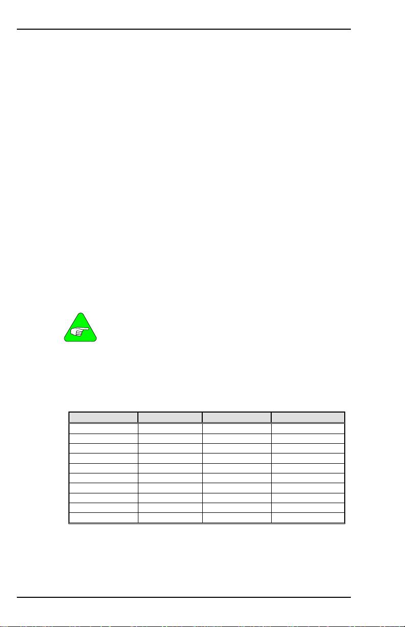
VARIABLE AND COMMAND LIST 09/05 Danaher Motion
RECING
Indicates if data recording is in progress.
0 = recording not in progress
1 = recording in progress
Firmware Versions: All Type: switch (R)
Range: 0, 1 Default: 0
Opmodes: All Drive Status: EN/DIS
Units: N/A EEPROM: No
RECOFF
Used to cancel/reset a recording process that has been armed but has
not triggered.
State before RECOFF State after RECOFF
RECRDY=0 RECRDY=1
RECING=1 RECING=0
RECDONE=0. RECDONE=0.
Firmware Versions: All Command Syntax: RECOFF
Opmodes: All Drive Status: EN/DIS
RECORD
Captures realtime variables to memory for retrieval or display using GET
or the MOTIONLINK PC Scope function. Set up RECORD before using
RECTRIG.
Variables that are recorded using this method are NOT
averaged using AVGTIME.
NOTE
1024 four-word buffers are available for use by RECORD, where one
word is defined as 16 bits. Most variables are one word in size, but
some are two words. You can record up to three variables, as long as
the total size of the three variables does not exceed 4 words. The
SERVOSTAR records:
Variable (Size) Variable (Size)
ANIN* (1 word) PCMD* (2 words)
I (2 words) PE* (2 words)
IA (1 word) PEXT* (2 words)
IC (1 word) PFB* (2 words)
ICMD (1 word) PRD (1 word)
IN1* (1 word) STOPPED* (1 word)
IN2* (1 word) V (1 word)
IN3* (1 word) VCMD (1 word)
INPOS* (1 word) VEXT* (1 word)
O1* (1 word)
* Added in firmware version 3.2.0
For example, a combination of V, VCMD, and VEXT is valid for
recording, because it only takes up 3 words of memory. However, a
combination of PCMD, PE, and PEXT (6 words total) cannot be
recorded.
80 M-SS-017-04 Rev. M VarCom Reference
Page 89

Danaher Motion 09/05 VARIABLE AND COMMAND LIST
RECORD also defines the time period between each consecutive
recorded data point and the variable names (up to three) being
recorded. An additional parameter defines the number of recorded data
points for each variable (up to 1024). Once they are recorded, variables
are retrieved using GET. See RECTRIG, RECDONE, RECING, and
RECRDY.
System variables must be preceded by a double-quote (“).
NOTE
Command Syntax:RECORD [sample time] [num points] [VAR1] {VAR2} {VAR3}
Firmware Versions: All Opmodes: All Drive Status: EN/DIS
Example: RECORD 10 100 “VCMD “V “PRD
(record 100 points for VCMD, V, and PRD every 5 milliseconds)
Range/Units: [sample time]:1 to 10,000(* 0.5 milliseconds)
[num points]: 1 to 1024 (1, 2, 4, 8, … 512, 1024)
[VARn]: a system variable, by ASCII (text) name
RECRDY
Indicates the ready status of the RECORD function. This variable
can be polled after a RECORD command is issued to determine if
the system is waiting for RECTRIG.
0 = RECTRIG has been received and record function is armed
1 = record function is waiting to be armed by RECTRIG
command
Firmware Versions: All Type: switch (R)
Range: 0, 1 Default: 1
Opmodes: All Drive Status: EN/DIS
Units: N/A EEPROM: No
RECTRIG
Sets up the trigger mechanism for RECORD. RECORD must be set up
before a RECTRIG is issued. Four parameters are required to set up
RECTRIG: Mode, Level, Location, and Direction.
MODE is a string variable that specifies the parameter that will trigger
recording. Mode can be a variable name or a triggering condition.
Mode determines what other parameters must be entered in order to
completely set up the trigger. Mode must be preceded by a doublequote when entered, as shown in the following table, which tells what
other parameters are required (LEVel, LOCation, and DIRection)
depending upon the selected Mode.
LEVEL specifies the value that the variable defined by Mode must
reach for recording to begin.
LOCATION specifies how many data points to save before the trigger
in the Recording buffer (see RECORD for a description of the 1024
data points that are available). When recorded data is retrieved and
displayed, the trigger point’s location in the 1024-point buffer is at the
place specified by Location.
VarCom Reference M-SS-017-04 Rev. M 81
Page 90
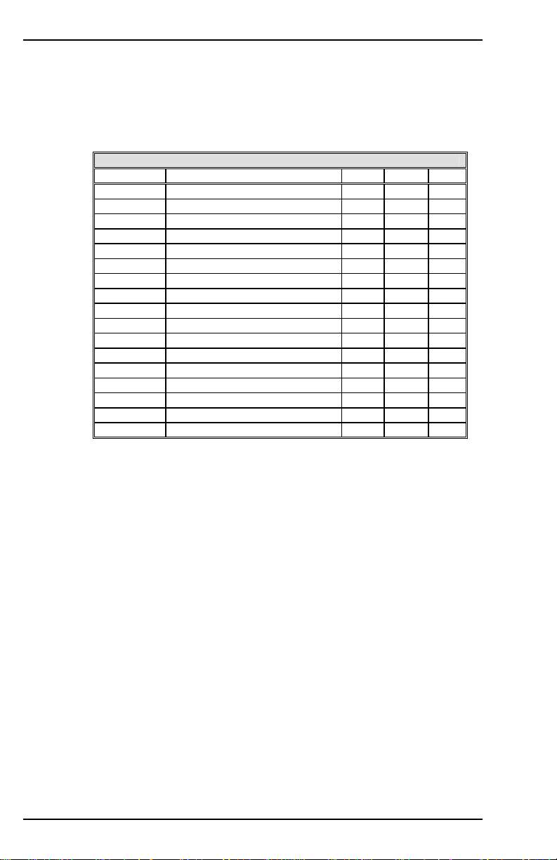
VARIABLE AND COMMAND LIST 09/05 Danaher Motion
DIRECTION has two meanings, depending upon the type of Mode
parameter that is used. For Mode variables (PRD, IA, IC), it defines
the direction the variable value must be changing when it crosses
Level in order to trigger recording (1 = increasing, 0 = decreasing).
For Mode switch inputs (CW, CCW, etc. - see below) it defines the
logic level the input must achieve in order to trigger recording (1 = HI,
0 = LOW).
Required RECTRIG Parameters Based on MODE Parameter
MODE DESCRIPTION LEV LOC DIR
“IA
“IC
“ICMD
“PCMD*
“PFB*
“PRD
“V
“VCMD
“CCW
“CW
“IN1*
“IN2*
“IN3*
“O1*
“RMT
“CMD
“IMM
* = firmware versions 3.2.0 and later
√ = Required Parameter
X = Don’t care. Something must be entered to make the command work,
Syntax:RECTRIG [mode] [level] [location] [direction]
Firmware Versions:
All
Example: RECORD 10 100 “VCMD “V “PRD
Range/Units: [mode]:see table above
Type: variable (R/W)
Opmodes: All
EEPROM: No Drive Status: EN/DIS
Trigger on Phase A Current
Trigger on Phase C Current
Trigger on Current Cmd
Trigger on Position Cmd
Trigger on Position Fdback
Trigger on PRD
Trigger on Velocity
Trigger on Velocity Cmd
Trigger on CCWLIM Sw X
Trigger on CWLIM Sw X
Trigger on IN1 Input X
Trigger on IN1 Input X
Trigger on IN1 Input X
Trigger on O1 Output X
Trigger on REMOTE Input X
Trigger on Next Command X
Trigger Immediately X X X
but it does not matter what is entered.
(record 100 points for VCMD, V, and PRD every 5 milliseconds)
[level]: depends upon the mode variable (range of PRD
levels is 0-65535. All others are -32768 to 32767)
[location]: 0 – 1023
[direction]: 0 or 1
Default: [level]: 0
[location]: 0
[direction]: 1
√ √ √
√ √ √
√ √ √
√ √ √
√ √ √
√ √ √
√ √ √
√ √ √
√ √
√ √
√ √
√ √
√ √
√ √
√ √
√
X
82 M-SS-017-04 Rev. M VarCom Reference
Page 91

Danaher Motion 09/05 VARIABLE AND COMMAND LIST
REFRESH
A command used when tuning the drive for COMPMODE 3. With the
Advanced Pole Placement algorithm utilized in the drive, the interaction
of the variables is too dramatic to allow variables to be changed one by
one. Therefore, as pole placement algorithm vector variables (VD, VF,
VH, and VR) are entered, the new values are buffered without changing
the actual values used by the control loops.
Once all desired new values have been entered, enter a REFRESH and
all vector variables are written to the control loops simultaneously.
Firmware Versions: All Command Syntax: REFRESH
Opmodes: 0, 1 Drive Status: EN/DIS
RELAY
Indicates the status of the Fault / Drive Up Relay.
0 = relay open
1 = relay closed
Firmware Versions: All Type: switch (R)
Range: 0, 1 Default: hardware defined
Opmodes: All Drive Status: EN/DIS
Units: N/A EEPROM: No
RELAYMODE
Sets the operation of the Drive Up / Drive Ready Relay.
0 = relay is closed when no faults exist
1 = relay is closed when ACTIVE equals 1
2 = during Active Disable, relay opens when the fault occurs (it does
not wait until DISTIME times out).
Firmware Versions: All Type: switch (R/W)
Range: 0, 1 Default: 0
Opmodes: All Drive Status: EN/DIS
Units: N/A EEPROM: Yes
REMOTE
Indicates the state of the external hardware enable input line. When
REMOTE=1, the software is ready (READY=1), and Dip Switch 8=OFF
(DIPEN=1), the drive is enabled (ACTIVE=1).
0 = remote enable input off
1 = remote enable input on
Firmware Versions: All Type: switch (R)
Range: 0, 1 Default: hardware defined
Opmodes: All Drive Status: EN/DIS
Units: N/A EEPROM: No
VarCom Reference M-SS-017-04 Rev. M 83
Page 92
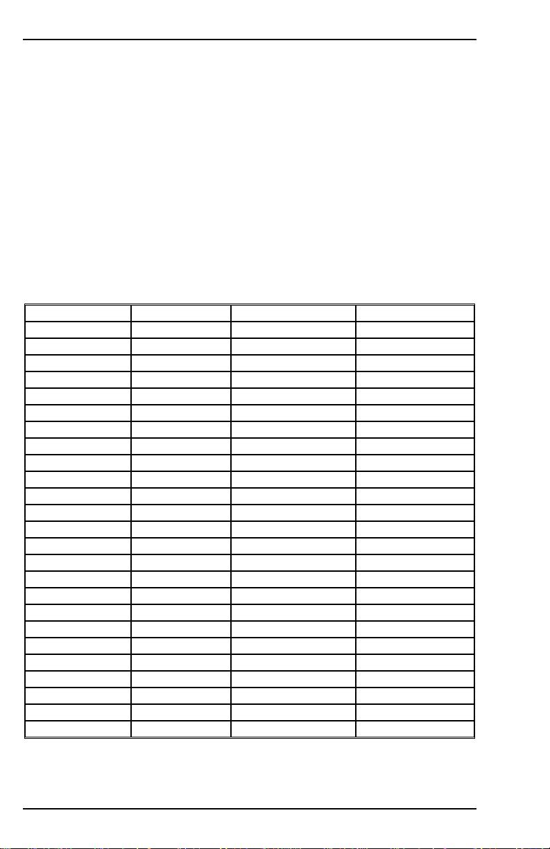
VARIABLE AND COMMAND LIST 09/05 Danaher Motion
RESBW
Set the cutoff frequency of the filter.
Syntax: RESBW <value> to set the cut-off frequency
Type: switch mode (R/W) Range: 300, 600, 1200
Units: Hz Default: 600
Opmodes: All Drive Status:DIS
Firmware: 6.3.3 and higher EEPROM: No
RESBW to read the cut-off frequency
RSTVAR
Sets all variables, switch variables, and switch mode variables to their
factory default settings. These settings are stated within this document
under the variable DEFAULT category. The default values of variables
loaded from a motor data file cannot be predicted and are denoted
motor data in the DEFAULT category.
Default values:
ACC = 400,000 ACKMODE = 0 ACTFAULT = 0 ANDB = 0
ANOFF = 0 ANOUT = 0 AVGTIME = 0 BW = 20
ANDG = 0 COMPFILT = 1 COMPMODE = 2 DEC = 400,000
DIR = 1 DISSPEED = 50 DISTIME = 100 ECHO = 1
ENCOUT = 1024 ENCOUTO = 1 FILTMODE = 0 FOLDMODE = 0
FOLDTIME = 30 GEAR = 1 GEARI = 1 GEARMODE = 3
GEARO = 1 GETMODE = 0 GPAFR = 0 GPAFR2 = 0
GPD = 0 GPI = 0 GPISATIN = 0 GPISATOUT = 0
GPVFR = 0 GV = 500 GVI = 20 HOMESPD = 100
HOMETYPE = 0 IENCSTART = 25 IFRIC = 0 IGRAV = 0
ILIM = IMAX ILIM2 = 100 ILSBMODE = 2 IN1MODE = 1
IN2MODE = 2 IN3MODE = 3 ISCALE = 1250 ISTOP = DICONT
IZERO = 20 KV = 1000 KVI = 1000 KVFR = 0
LIMDIS = 0 LMJR = 0 MPFHZ1 = 500 LPFHZ2 = 500
MAPOS = 0 MASPEED = 0 MFBDIR = 0 MFOLDD = 1200
MFOLDDIS = 0 MFOLDR = 1800 MFOLDT = 600 MIDISTx = 0
MISPEEDx = 100 MSININT = 256 MPHASE = 0 MSG = 1
MSINFRQ = 1 NOTCHBW = 1 NOTCHHZ = 500 O1MODE = 6
O1RST = VOSPD O1TRIG = 1000 OPMODE = 1 PCMDMODE = 0
PEMAX = 0 PLIM = 0 PMAX = 2,000,000,000 PMIN = 2,000,000,000
PROFMODE = 0 PROFSCRV = 50 PROMPT = 1 RELAYMODE = 0
SININTOUT = 1 STOPPED = 0 TF = 100 THERMODE = 0
THERMTIME = 30 THERMTYPE = 0 UNITS = 0 UVMODE = 0
UVTIME = 30 UVRECOVER = 0 VD = 0 VF = 1,000,000
VH = 0 VLIM = VMAX VOSPEED = 1.2 * VLIM VR = 0
XENCDIR = 0 XENCRES = 1024
Firmware Versions: All Command Syntax: RSTVAR
Opmodes: 0, 1 Drive Status: DIS
84 M-SS-017-04 Rev. M VarCom Reference
Page 93

Danaher Motion 09/05 VARIABLE AND COMMAND LIST
S
Stops motor motion in all OPMODES. Deceleration ramp control is
always used, using the rate specified by DECSTOP. After the profile
generator reaches 0 speed, the drive waits for the time period specified
by DISTIME and disables the drive.
This command is a one-key hot button, similar to K , but with an active
stop function controlled by the drive (no coasting of the motor occurs, as
is possible with K).
Firmware Versions: All Command Syntax: S
Opmodes: 0, 1 Drive Status: EN/DIS
SAVE
Copies all system configuration variables from working RAM to nonvolatile memory (EEPROM). This command must be executed in order
to retain setting changes during power cycling. The SAVE command
takes about 2 seconds to execute.
Firmware Versions: All Command Syntax: SAVE
Opmodes: 0, 1 Drive Status: EN/DIS
SERIALNO
Indicates the serial number of the drive in which the firmware is
installed. This variable is password protected. This variable is included
in VER.
Firmware Versions: All Type: string variable (R)
Range: 10 ASCII characters Default: blanks
Opmodes: All Drive Status: EN/DIS
Units: N/A EEPROM: Yes
SININIT
Initialize or reset the sine calibration process.
Syntax: SININIT Type: Command
Range: N/A Default: 0
Opmodes: All Drive Status: DIS
Firmware: 6.2.0 and higher EEPROM: No
SININTOUT
Sets an interpolation factor of the sine encoder board for the equivalent
encoder output. For sine encoder systems, the encoder output value is
(ENCOUT) = MENCRES * SININTOUT / ENCOUTO. See MSINFRQ.
Firmware Versions: 3.3.0 and later Type: switch mode (R/W)
Range: 1, 2, 4, 8, 16, 32, 64, 128 Default: 1
Opmodes: All Drive Status: DIS
Units: N/A EEPROM: Yes
VarCom Reference M-SS-017-04 Rev. M 85
Page 94

VARIABLE AND COMMAND LIST 09/05 Danaher Motion
SININITST
Queries the status of the sine calibration process. The following values
may be returned by the query:
0 – No request
1 – Process running
2 – Motor velocity too high. The sine frequency must not exceed 250
Hz. When speed is reduced, the status returns to 1 (running).
3 – Process completed
4 – Defaults loaded. Defaults are loaded when the calibration process
has never been performed, such as in a new drive.
5 – Internal failure
Type: Read-only Range: 0 .. 5
Opmodes: All Drive Status: EN/DIS
Firmware: 6.2.0 and higher
EEPROM: No
SINPARAM
Queries or sets the sine calibration values. There are four calibration
parameters when working with a sine encoder, and six calibration
parameters when working with a resolver. All are signed hexadecimal
values.
Sine offset and cosine offset:
Multiply by (10000/32768) to get value in millivolts. This offset is at the
ADC terminal (after the sine and cosine signals were amplified).
Sin to cos match gain and scale:
The algorithm requires that the sine and cosine signals should have the
same amplitude. This value equals (gain / 2^scale), and represents the
amplitude difference of the sine and cosine signals. It should be close to
1. The firmware multiplies the sine signal samples by this value to get
the same amplitude for the sine and the cosine signals.
Full-scale gain and scale (relevant for Resolver ONLY):
The algorithm requires that the sine and cosine signals should be scaled
to 32768. The final value equals (gain / 2^scale), and it represents the
factor to multiply the sine and cosine signals. It should be in the range
1.2 to 1.3. The firmware multiplies the sine and cosine signals samples
by this value.
Syntax for set: SINPARAM<Sine offset><Cosine offset><Sine to Cosine
match gain> <Sine to Cosine match scale> <full-scale
gain> <full-scale scale>
Last 2 parameters relevant for resolver feedback only.
NOTE
86 M-SS-017-04 Rev. M VarCom Reference
Page 95
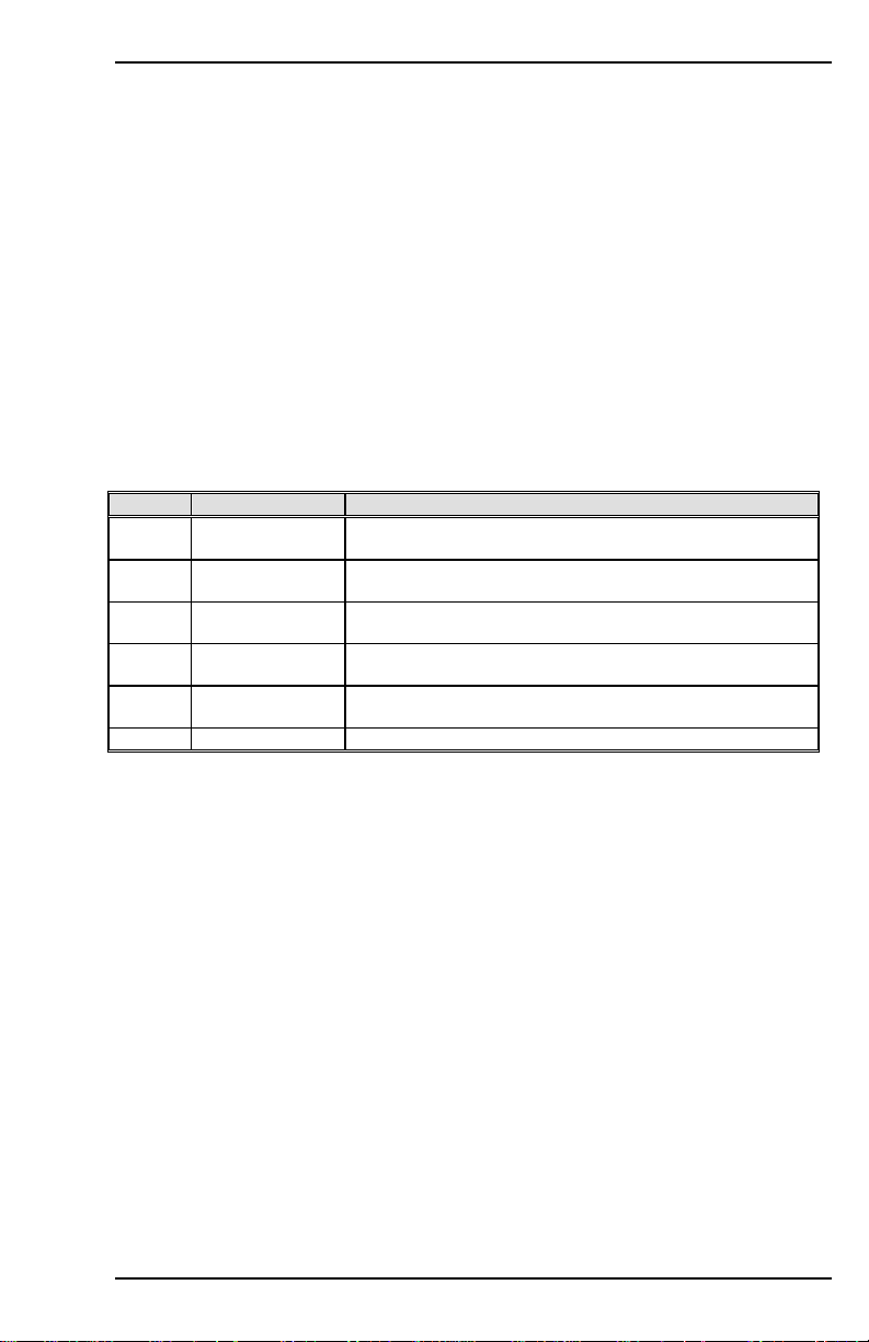
Danaher Motion 09/05 VARIABLE AND COMMAND LIST
Syntax for query: SINPARAM
Range: Sine offset: -32768 .. 32767
Cosine offset: -32768 .. 32767
Sine to Cosine match gain: 1 .. 32767
Sine to Cosine match scale: 1 .. 15
full-scale gain: 1 .. 32767
full-scale scale: 1 .. 15
Default: 0h 0h 4000h Eh 4000h Eh (last 2 are for resolver only)
Type: variable (R) Units: Internal
Opmodes: All Drive Status: DIS
Firmware: 6.3.3 and higher EEPROM: Yes
Limitations: Not yet supported by MOTIONLINK
STAT
Outputs a drive status summary word to the serial port. The summary
word is in ASCII-hex format, prefixed by the letter H. See STATUS for
information on how to obtain more detailed drive status information. The
format of the STAT word:
Bit # Function Convention
0
(LSB)
1 Fault Status 1 = fault exists
2 Safety Status 1 = safety feature triggered/inactive*
3 Special Mode
4** Hold Mode
5-15 not used
*CWLIM=1, CCWLIM=1, LIMDIS=1, THERMODE=1 or 2, or FOLD=1, or (PLIM>0 and PFB>PMAX), or
(PLIM>0 and PFB<PMIN).
** Prior to firmware version 2.0.0, Bit 4 was undefined.
Disable Status 1 = drive is disabled
Status
Status**
Firmware Versions: All Type: variable (R)
Range: see above Default: N/A
Opmodes: All Drive Status: DIS
Units: N/A EEPROM: No
0 = drive is enabled
0 = no fault exists
0 = drive is safe
1 = Step, Burnin, or Zero is active
0 = normal
1 = drive is in Hold mode, in position, or stopped
0 = drive is not in Hold mode
STATUS
Outputs the drive status detail words to the serial port. Five words are
transferred in ASCII-HEX format, with each word preceded by the letter
H. The words are separated by a space.
The following tables break the status words down bit by bit (bit 15 =
MSB; bit 0 = LSB; n/u = not used). For all bits, 0=false and 1=true.
VarCom Reference M-SS-017-04 Rev. M 87
Page 96
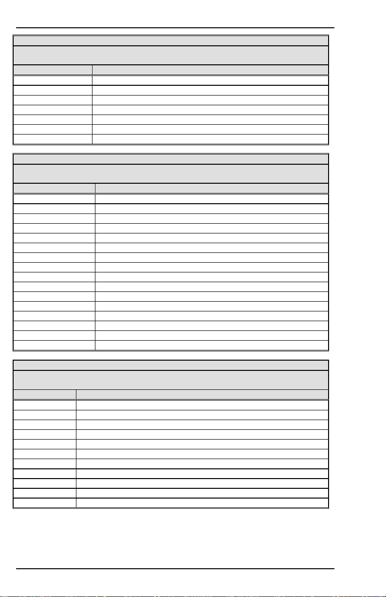
VARIABLE AND COMMAND LIST 09/05 Danaher Motion
STATUS Word 1: Disable Status Word
If the drive is disabled (Bit 0 of the STAT word = 1), the process(es) which have
caused that disable condition will have their bits set to 1 in this word.
Bit # Description
0 (LSB) Remote disable (REMOTE = 0)
1 Software disable (SWEN = 0)
2 DIP switch disable (DIPEN = 0)
3 Fault disable
4 Velocity loop design failure
5 Encoder not initialized
6-15 not used
STATUS Word 2: Fault Status Word
If a fault exists (Bit 1 of the STAT word = 1), the fault(s) has the corresponding bits
set to 1 in this word.
Bit # DESCRIPTION
0 (LSB) Drive over temperature
1 Over voltage condition
2 Over current condition
3 Feedback loss
4 Under voltage condition
5 Motor over temperature
6 Analog supply fault
7 Over speed condition
8 EEPROM fault
9 EEPROM checksum fault
10 No comp (compensation) for the motor
11 Foldback condition
12 not used
13 Overtravel fault
14 Position deviation fault
15 not used
STATUS Word 3: Safety Status Word
If safety of the drive is compromised (Bit 2 of the STAT word = 1), the condition
causing that state has its corresponding bit set to 1 in this word.
Bit # Description
0 (LSB) CWLIM = 1 (motor has reached CW travel limit)
1 CCWLIM = 1 (motor has reached CCW travel limit)
2 LIMDIS = 1 (limit switch function disabled by user)
3 THERMODE = 1, 2, 3 (set to non-zero by the user)
4 FOLD = 1 (drive current foldback mode)
5* LIMDIS=0 & CW switch not routed (INxMODE 1)
6* LIMDIS=0 & CCW switch not routed (INxMODE 2)
7*** Positive Overtravel (PFB > PMAX) with PLIM > 0
8*** Negative Overtravel (PFB < PMIN) with PLIM > 0
9**** MFOLD = 1 (motor current foldback mode)
10-15 not used
88 M-SS-017-04 Rev. M VarCom Reference
Page 97
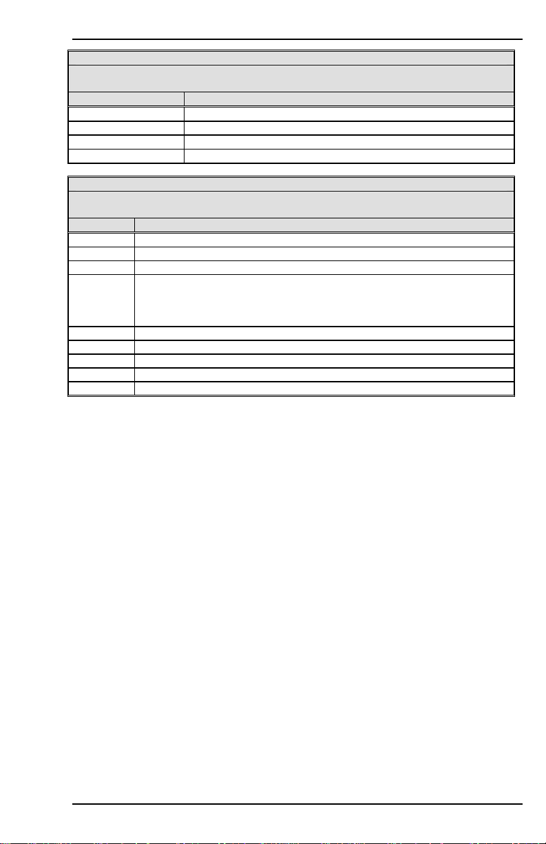
Danaher Motion 09/05 VARIABLE AND COMMAND LIST
STATUS Word 4: Special Mode Status Word
If the drive is in a special operating mode (Bit 3 of the STAT word = 1), the drice's
special mode has its corresponding bit set to 1 in this word.
Bit # DESCRIPTION
0 (LSB)
1 Drive is in Burnin mode (factory function)
2
3-15 not used
STATUS Word 5: Hold Mode Status Word
If the drive is in Hold mode (Bit 4 of the STAT word = 1), the condition causing the
drive to enter Hold mode has its corresponding bit set to 1 in this word).
Bit # Description
0 (LSB) User request (user set HOLD = 1)
1 DIP switch setting (DIP switch 7 = 1)
2 Drive is in Active disable state
3 Limit switch(es) tripped:
1. velocity command is in direction of tripped switch in opmode 0 or 1
2. both limit switches are activated
4** User input switch hold (INxMODE=19)
5** Internal hold request during homing process.
6-10 not used
11++ Analog position hold before homing
12-15 not used
Firmware Versions: All, with exceptions:
Type: variable (R) Range: see above
Default: N/A Units: N/A
Opmodes: All
EEPROM: No
Drive is in Step mode (see STATUS2)
Drive is in Zeroing mode (see XENCRES)
with drive enabled; or
*-versions 2.1.0 and later
**-versions 3.0.0 and later
*** - versions 3.1.0 and later
**** - versions 3.2.0 and later
++ - versions 3.3.0 and later
Drive Status: EN/DIS
STATUS2
Outputs drive status detail words to the serial port. Four words are
transferred in ASCII-HEX format, with each word preceded by the letter
H.
The following tables break the status words down bit by bit (bit 15 =
MSB; bit 0 = LSB; n/u = not used). For all bits, 0=false and 1=true.
VarCom Reference M-SS-017-04 Rev. M 89
Page 98
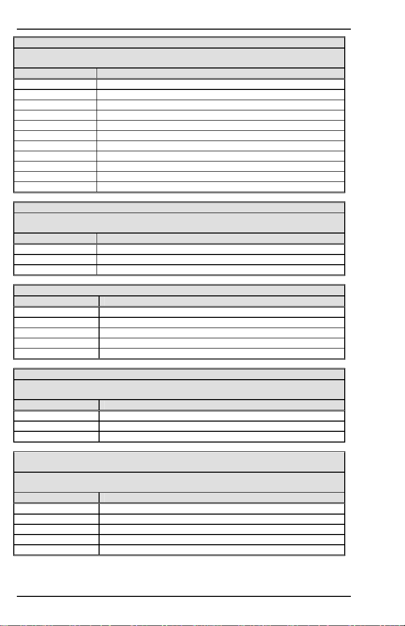
VARIABLE AND COMMAND LIST 09/05 Danaher Motion
STATUS2 Word 1: Feedback Loss Status Word
If the drive has experienced a feedback loss fault (Bit 3 of STATUS Word 2 = 1), the
condition causing the fault has its bit set to 1 in this word.
Bit # DESCRIPTION
0 (LSB) Resolver line break
1 Resolver/Digital Converter Error bit (following err)
2 Sine encoder initialization failed
3 Line break of encoder A/B input
4 Line break of encoder index input
5 Illegal halls state
6 Line break of encoder C/D input (sine encoder)
7 A/B lines out of range (sine encoder)
8 Burst overflow (sine encoder)
9* External feedback line break
10-15 not used
STATUS2 Word 2: Analog Supply Fault Status Word
If the drive has experienced an analog supply fault (Bit 6 of STATUS Word 2 = 1),
the condition causing the fault has its bit set to 1 in this word.
Bit # Description
0 (LSB) Positive analog supply fault
1 Negative analog supply fault
2-15 not used
STATUS2 Word 3: Position Deviation and Over Travel Fault Status Word
Bit # Description
0 Internal Numerical Position Deviation
1
Pos. Error (PE) exceeded max PE limit (PEMAX)
2 Positive Over-travel (PFB > PMAX) with PLIM=1
3 Negative Over-travel (PFB < PMIN) with PLIM=1
4-15 Reserved
STATUS2 Word 4: Limit Switches Status Word
If the drive has experienced a limit switch fault (Bit 3 of STATUS Word 5 = 1), the
condition causing the fault has its bit set to 1 in this word.
Bit # Description
0 (LSB) CW Limit Switch tripped (CWLIM=1)
1 CCW Limit Switch tripped (CCWLIM=1)
2-15 not used
STATUS2 Word 5: Encoder Initialization Status Word
(for firmware version 3.3.0 and higher)
If the drive has experienced a fault during encoder initialization (Bit 5 of STATUS
Word 1=1), the condition causing the fault has its bit set to 1 in this word.
Bit # Description
0 (LSB)
MENCRES, MPOLES or low IENCSTART failure
1 Phase A current mismatch
2 Phase C current mismatch
3 Limit switch tripped
4-15 not used
90 M-SS-017-04 Rev. M VarCom Reference
Page 99
Danaher Motion 09/05 VARIABLE AND COMMAND LIST
STATUS2 Word 6: Over speed Status Word
(firmware version 3.3.0 and higher)
This status word details the cause of over speed fault.s.
Bit # Description
0 (LSB) velocity feedback > VOSPD
1 velocity feedback > 1.8*VLIM
2-15 not used
- firmware version 3.3.0 and later
Firmware Versions: 2.1.0 and later Type: variable (R)
Range: see above Default: N/A
Opmodes: All Drive Status: DIS
Units: N/A EEPROM: No
STATUS2
Returns drive status words to the serial port. Six words are transferred in
ASCII-HEX format, with each word preceded by the letter H. The
encoder initialization status is reported in word 5, which is described
below. Bit 2 in the first word indicates if the encoder initialization process
has failed.
STATUS2 Word 1: Feedback Loss Status Word
If the drive has experienced a feedback loss fault (Bit 3 of STATUS Word 2 = 1), the
condition causing the fault has its bit set to 1 in this word.
Bit # Description
0 (LSB) Resolver line break
1 Resolver/Digital Converter Error bit (following err)
2 Sine encoder initialization failed
3 Line break of encoder A/B input
4 Line break of encoder index input
5 Illegal halls state
6 Line break of encoder C/D input (sine encoder)
7 A/B lines out of range (sine encoder)
8 Burst overflow (sine encoder)
9* External feedback line break
10-15 not used
STATUS2 Word 2: Analog Supply Fault Status Word
If the drive has experienced an analog supply fault (Bit 6 of STATUS Word 2 = 1),
the condition causing the fault has its bit set to 1 in this word.
Bit # Description
0 (LSB) Positive analog supply fault
1 Negative analog supply fault
2-15 not used
VarCom Reference M-SS-017-04 Rev. M 91
Page 100
VARIABLE AND COMMAND LIST 09/05 Danaher Motion
STATUS2 Word 3: Position Deviation and Over Travel Fault Status Word
Bit # Description
0 Internal Numerical Position Deviation
1
2 Positive Over-travel (PFB > PMAX) with PLIM=1
3 Negative Over-travel (PFB < PMIN) with PLIM=1
4-15 Reserved
STATUS2 Word 4: Limit Switches Status Word
If the drive has experienced a limit switch fault (Bit 3 of STATUS Word 5 = 1), the
condition causing the fault has its bit set to 1 in this word.
Bit # Description
0 (LSB) CW Limit Switch tripped (CWLIM=1)
1 CCW Limit Switch tripped (CCWLIM=1)
2-15 not used
STATUS2 Word 5: Encoder Initialization Status Word
(firmware 6.3.3 and higher)
If the drive has experienced a fault during encoder initialization (Bit 5 of STATUS
Word 1 = 1), the condition causing the fault has its bit set to 1 in this word.
Bit# Description
0 (LSB)
1 Phase A current mismatch
2 Phase C current mismatch
3 Limit switch tripped
4 Internal fault
5 Runaway – algorithm failed to due excessive motion. Either
6
7
8-15 Not used
STATUS2 Word 6: Over speed Status Word
(firmware version 3.3.0 and higher)
This status word details the cause of over speed fault.s.
Bit # Description
0 (LSB) velocity feedback > VOSPD
1 velocity feedback > 1.8*VLIM
2-15 not used
- firmware version 3.3.0 and later
Range: The bits in status word 5 are described in the following table. Bits 4-7
Default: 0 Opmodes: All
Drive Status: DIS EEPROM: Yes
Pos. Error (PE) exceeded max PE limit (PEMAX)
MENCRES, MPOLES or low IENCSTART failure
IENCSTART or INITGAIN is too high. Make sure IENCSTART is
set correctly. Reduce the value of INITGAIN.
Motion profile mismatch. Adjust the value of INITGAIN.
Insufficient motion. Increase IENCSTART or INITGAIN.
are relevant for INITMODE 2.
STEP
Generates a step or square wave velocity command. This command is
used to record the drive response after RECTRIG has been set up to
define the trigger as occurring after the next command. This command
takes 2, 3, or 4 parameters.
92 M-SS-017-04 Rev. M VarCom Reference
 Loading...